

Page 1

Installation and Operation Manual
X-VA-1250-55 Series-eng
Part Number: 541B164AAG
May, 2011
Brooks® 1250-55 Series Flowmeters
Brooks® Models 1250-55
Standard glass tube flowmeters are available in various
ranges and configurations. The meters have 65
millimeter and 150 millimeter reference scales, and are
supplied with flow curves for air and water. At your
request, flow curves for other gases and liquids can be
supplied, and direct read scales are available on a
special order basis.
UNPACKING
Precautions have been taken to prevent any damage
from occurring during shipment. However, if the meter
is received damaged, report it to the carrier
immediately. Verify that you have the model and flow
range that you require.
MILLIMETER REFERENCE SCALES
To ensure accurate flowrate readings on all flowmeters
with millimeter reference scales, the following should be
verified: the tube part number and revision level printed
on the top of the tube (for example, 1G04 R4) should
correspond with the tube number and revision level on
the Flow Curve Data Sheet. The gas or liquid flowing
through the meter and the float material should also
match the specification on the Flow Curve Data Sheet.
ACHIEVING ACCURATE FLOWRATES
To obtain an accurate flowrate, the float must be read
from the center of the ball. Additionally, the flowmeter
should be installed in a manner, which minimizes both
external vibrations and internal flow variations. Special
care should be taken so that the connections to the
meter's inlet and outlet fittings do not overly restrict the
liquid or gas flow being metered. This could result in a
reduced flow volume, preventing the meter from
reaching its maximum flowrate. Furthermore, internal
pressures could be affected, which can cause
inaccurate flow readings. Prior to use, any air/gas
trapped in the meter should be slowly purged and the
meter should be checked for leaks.
INSTALLATION
The flowmeter is capable of being panel mounted or
mounted on a leveling tripod base. In order to mount
the meter on a panel, two clearance holes must be
drilled. (Refer to Figure 1 for the correct locations of the
19/32" diameter clearance holes.) The meter is
secured to the panel using the pal nuts, which are
supplied with the meter. The meter can also be
mounted on an optional leveling tripod base for
freestanding use. The meter is supplied with 1/8-27
FNPT non-rotating fittings. When installing the fittings
the meter, place the appropriate size wrench on the hex
to prevent the inlet and outlet fittings from rotating.
(Use pipe thread sealant or Teflon® tape to achieve a
positive seal.) When installing the 1/8-27 MNPT fittings
into the meter, torque to 60 in-lbs. maximum. Failure to
hold the inlet/outlet fittings or over-torquing the fittings
could cause serious damage to the fittings or the meter
backplate.
CLEANING
Occasional cleaning may be required if dirt appears in
the flow tube or if float movement becomes restricted.
The tube assembly can be removed from the meter
frame for cleaning or replacement of parts without
removing the meter from the process line. The tube
and float should be cleaned with a mild liquid detergent
and a soft brush or swab. All pieces should be rinsed/
flushed with clean water, and dried thoroughly with
clean dry air or nitrogen.
DISASSEMBLY
If the meter is to be disassembled for any reason; be
sure to first bleed off any pressure in the meter. With a
5/32" Allen wrench, turn the jackscrew counterclockwise until it reaches a stop. Gently remove the
tube assembly from the meter frame. Remove the lens
caps and shield. Remove the top float stop and the
float from the top of the tube. Next, remove the bottom
float stop from the bottom of the tube. To remove a
control valve, turn counter-clockwise with a ½" wrench.
REASSEMBLY
Check to make sure that all parts are clean and dry.
Install the bottom float stop into the bottom of the flow
tube. Install the ball float and the top float stop from the
top of the tube. Install the bottom lens caps on the
tube. Insert the tube in the lens shield and install the
top lens cap. Check the top and bottom gaskets and
replace, if necessary. Carefully slide the tube assembly
back into the meter, making sure that it is properly
aligned with the scale facing forward. Tighten the
jackscrew by turning clockwise until the gaskets make
contact with the tube. Carefully torque to 1-1¾ in-lbs. to
achieve a positive seal. Do not over-tighten. To
replace a control valve, turn clockwise with a ½" openend wrench. Close the valve and slowly pressurize the
meter. Check for leaks before resuming operation.
Page 2
Brooks® 1250-55 Series Flowmeters
Installation and Operation Manual
X-VA-1250-55 Series-eng
Part Number: 541B164AAG
May, 2011
SPECIFICATIONS
ACCURACY:
FLOATS:
FRAME BACKPLATE:
END BLOCKS AND
ELASTOMERS:
FITTINGS:
GLASS TUBE:
MAXIMUM
TEMPERATURE:
MAXIMUM
PRESSURE:
± 10% Full Scale – 65 mm
± 5% Full Scale – 150 mm
Black Glass Ball Float
Sapphire Ball Float
Stainless Steel Ball Float
Tungsten Carbide Float
Tantalum Float
Anodized Aluminum
Aluminum with Buna-N
Brass with Buna-N
Stainless Steel with Viton®
fluoroelastomer
⅛-27 FNPT Fittings
Precision Formed Borosilicate
200°F (93 °C)
200 PSI (13.8 Bar)
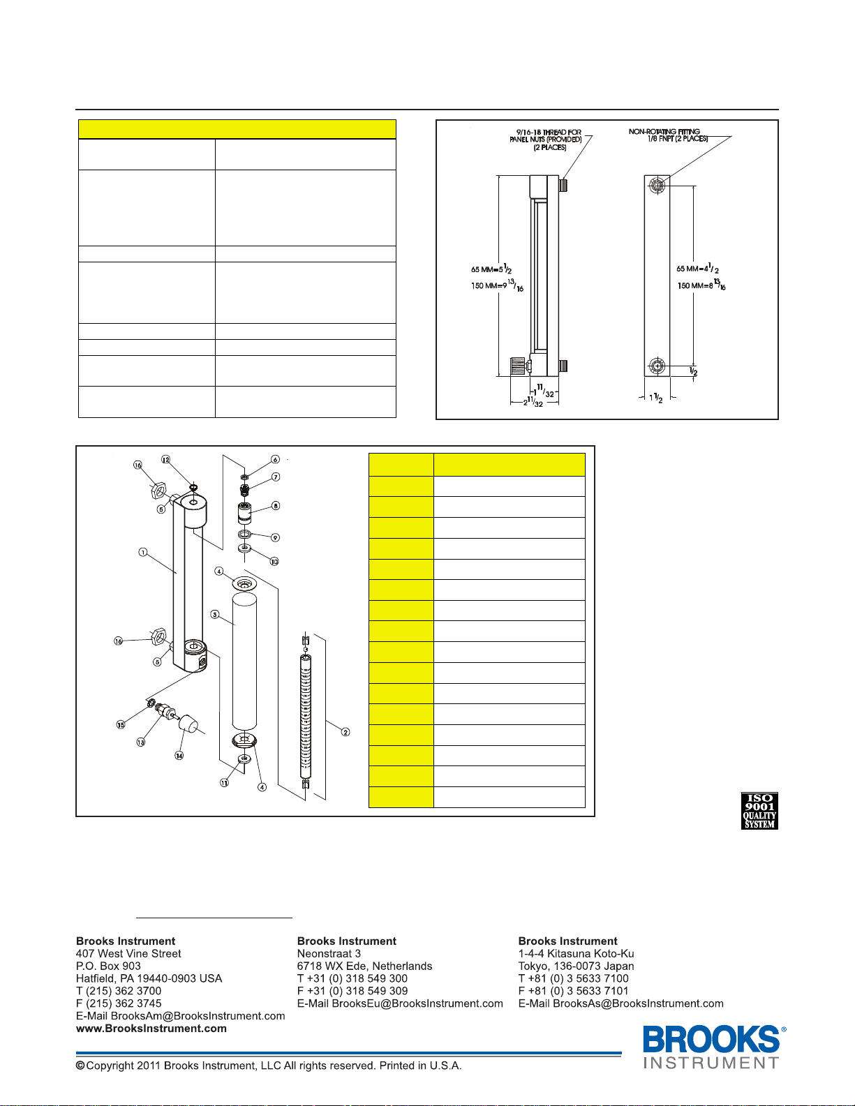
Number Description
Figure 2 Parts List for Brooks 1250-55 Series Flowmeters
Figure 1 Dimensions for Brooks 1250-55 Series Flowmeters
1
2
3 Lens
4
5
6
7
8 Jack Plug
9
10
11
12
13
14
15
16
Frame Assembly
Tube Assembl y
Lens End Cap(s)
Fitting
Jack Screw O-ring
Jack Screw
Jack Plug O-ring
Top Gasket
Bottom Gasket
Retaining Clip
Optional Valve
Valve Knob
Valve O-ring
Panel Nuts
Due to Brooks Instrument’s continuous improvement of our products, all specifications are subject to change without
notice. When ordering parts please include part description, item number (see Figure 2) and type of material required.
If you have any questions regarding installation, maintenance, replacement or use of this flowmeter, please visit our
website at
www.BrooksInstrument.com for Customer Service contact information.
 Loading...