

Broan QS336WW, QS336BC Installation Guide
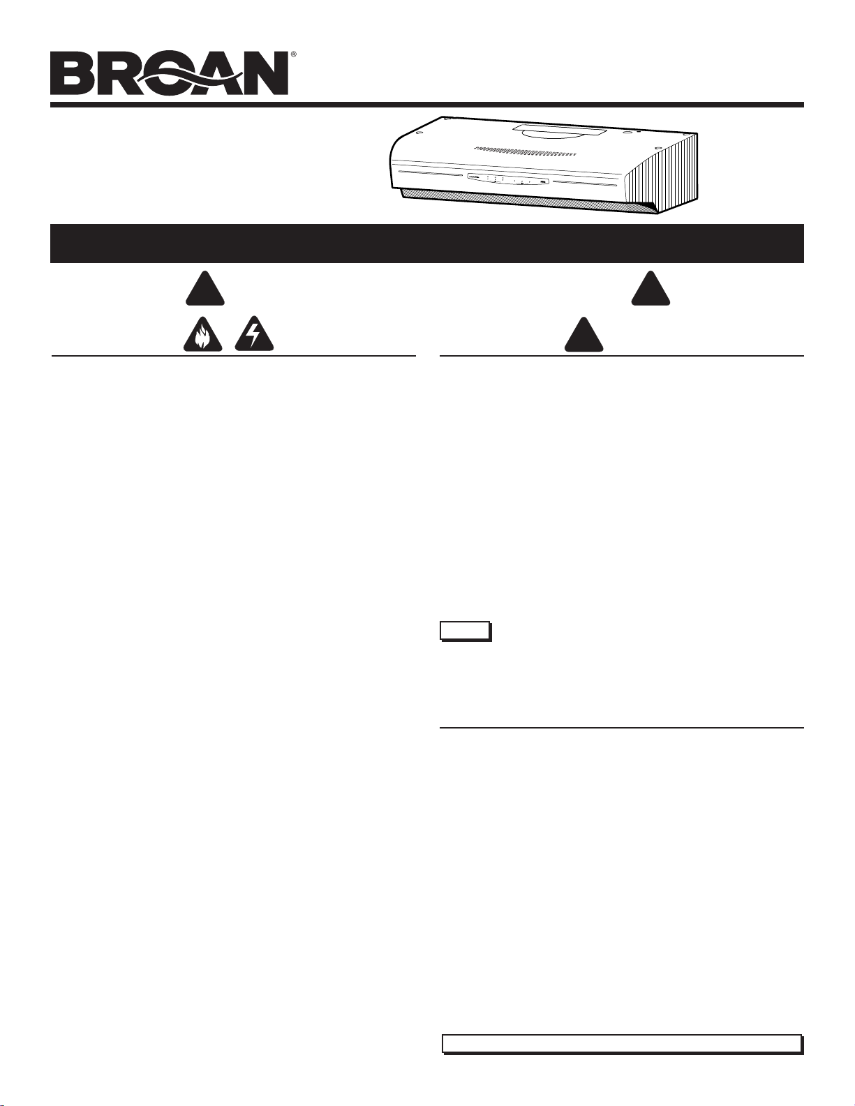
ALLURE
®
QS3 SERIES
RANGE HOOD
ALLURE
®
QS3 SERIES
RANGE HOOD
READ AND SAVE THESE INSTRUCTIONS
!
FOR DOMESTIC COOKING ONLY
WARNING
TO REDUCE THE RISK OF FIRE, ELECTRIC SHOCK, OR INJURY TO
PERSONS, OBSERVE THE FOLLOWING:
1. U s e this unit only in the manner intended by the manufacturer. If you have
questions, contact the manufacturer at the address or telephone number
listed in the warranty.
2. Before servicing or cleaning unit, switch power off at service panel and
lock the service disconnecting means to prevent power from being
switched on accidentally. When the service disconnecting means cannot
be locked, securely fasten a prominent warning device, such as a tag, to
the service panel.
3. Installation work and electrical wiring must be done by a qualified
person(s) in accordance with all applicable codes and standards, including fire-rated construction codes and standards.
4. Sufficient air is needed for proper combustion and exhausting of gases
through the flue (chimney) of fuel burning equipment to prevent backdrafting. Follow the heating equipment manufacturer’s guideline and safety
standards such as those published by the National Fire Protection Association (NFPA), and the American Society of Heating, Refrigeration and
Air Conditioning Engineers (ASHRAE), and the local code authorities.
5. When cutting or drilling into wall or ceiling, do not damage electrical wiring
and other hidden utilities.
6. To reduce the risk of fire or electric shock, do not use this range hood
with an additional speed control device.
7. Ducted
8. To reduce the risk of fire, use only metal ductwork.
9. Use with approved cord-connection kit only.
10. This unit must be grounded.
TO REDUCE THE RISK OF A RANGE TOP GREASE FIRE:
1. Never leave surface units unattended at high settings. Boilovers cause
2. Always turn hood ON when cooking at high heat or when cooking flaming
3. Clean ventilating fans frequently. Grease should not be allowed to
4. Use proper pan size. Always use cookware appropriate for the size of
TO REDUCE THE RISK OF INJURY TO PERSONS IN THE EVENT OF A
RANGE TOP GREASE FIRE, OBSERVE THE FOLLOWING:*
1. SMOTHER FLAMES with a close-fitting lid, cookie sheet, or metal tray,
2. NEVER PICK UP A FLAMING PAN — You may be burned.
3. DO NOT USE WATER, including wet dishcloths or towels - violent steam
4. Use an extinguisher ONLY if:
fans must always
smoking and greasy spillovers that may ignite. Heat oils slowly on low or
medium settings.
foods.
accumulate on fan or filter.
the surface element.
then turn off the burner. BE CAREFUL TO PREVENT BURNS. If the
flames do not go out immediately, EVACUATE AND CALL THE FIRE
DEPARTMENT.
explosion will result.
A. You know you have a Class ABC extinguisher and you already know
how to operate it.
B. The fire is small and contained in the area where it started.
C. The fire department is being called.
D. You can fight the fire with your
* Based on “Kitchen Fire Safety Tips” published by NFPA.
be vented to the outdoors.
back to
an exit.
Page 1
Patent No.:
US D450, 829 S
!
CAUTION
1. For indoor use only.
2. For general ventilating use only. Do not use to exhaust hazardous or
explosive materials and vapors.
3. To avoid motor bearing damage and noisy and/or unbalanced impellers,
keep drywall spray, construction dust, etc. off power unit.
4. For best capture of cooking impurities, your range hood should be
mounted so that the top of the hood is 24-30” above the cooking surface.
5. Please read specification label on product for further information and
requirements.
Installer: Leave this manual with
the homeowner.
Homeowner: Operating and
Cleaning information on page 6.
NOTE If hood is to be installed Non-Ducted:
Purchase a set of (2) non-ducted filters from your
local distributor or retailer and attach them to the
aluminum mesh filters.
TABLE OF CONTENTS
This manual is divided into sections as follows:
“PREPARE HOOD LOCATION”
Run ductwork from roof or wall cap, and electrical wiring from service
panel - to installation location
“PREPARE THE HOOD”
Get your hood ready for installation
“CONNECT WIRING”
Make electrical wiring connections to hood
“INSTALL HOOD”
Secure hood to cabinet and ductwork - install bulbs and filters
“OPERATION”
How to use the hood controls
“CLEANING”
Keep your hood in top working condition
“SERVICE PARTS”
Part numbers and exploded view of hood components
“WARRANTY”
One-year limited warranty and how to contact us
Register your product online at: www.broan.com/register
!
ALLURE
®
QS3 SERIES
RANGE HOOD
Page 2
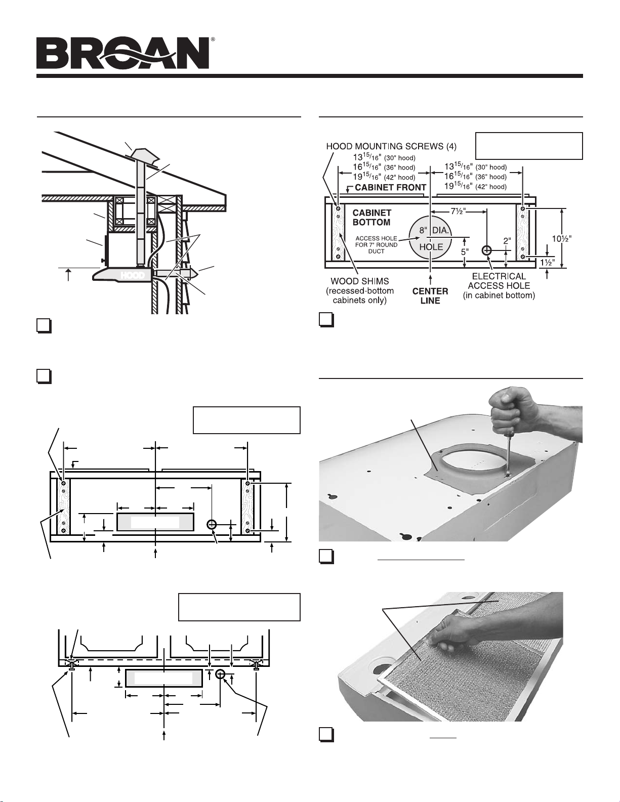
PREPARE HOOD LOCATION
ROOF CAP
SOFFIT
CABINET
HOODHOOD
24" - 30" ABOVE
COOKING SURFACE
1 Determine whether hood will discharge vertically (3¼” x 10”
or 7” Round), or horizontally (3¼” x 10” only). For vertical or
horizontal discharge, run ductwork between the hood location
and a roof cap or wall cap. For best results, use a minimum
number of transitons and elbows.
2 Use diagrams, below, for proper placement of ductwork and
electrical cutout in cabinet or wall. For a non-ducted installation, DO NOT cut a duct access hole.
HOOD MOUNTING SCREWS (4)
13
16
19
15
15
15
/
"
16
/
"
16
/
"
16
(30" hood)
(36" hood)
(42" hood)
CABINET FRONT
3¼" X 10" or
7" ROUND DUCT
(For vertical
discharge)
HOUSE WIRING
(Top or Back of hood)
3¼" X 10" DUCT
(For horizontal discharge)
VERTICAL DUCTING
15
/
13
"
(30" hood)
16
15
/
16
"
(36" hood)
16
15
/
"
(42" hood)
16
19
WALL CAP
3¼” X 10”
PREPARE HOOD LOCATION
7” ROUND
VERTICAL DUCTING
3 Run house wiring between service panel and hood location.
PREPARE THE HOOD
7” ROUND
DUCT PLATE
5"
1¼"
WOOD SHIMS
(recessed-bottom
cabinets only)
WOOD SHIMS
(recessed-bottom
cabinets only)
3¾"
CABINET
BOTTOM
15
13
/
16
15
16
/
16
15
19
/
16
HOOD
MOUNTING
SCREWS (4)
7½"
CABINET BOTTOM
5¼"
VERTICAL DUCT
ACCESS HOLE
5¼"
CENTER
LINE
HORIZONTAL DUCTING
CABINET FRONT
HORIZONTAL DUCT
ACCESS HOLE
5¼"
13
16
19
LINE
"
(30" hood)
"
(36" hood)
"
(42" hood)
5¼"
CENTER
2"
ELECTRICAL
ACCESS HOLE
(in cabinet bottom)
3¼” X 10”
1
"
/
¾"
8
7½"
15
"
(30" hood)
/
16
15
"
(36" hood)
/
16
15
"
(42" hood)
/
16
ELECTRICAL
ACCESS HOLE
(in wall)
10½"
1½"
1 Remove 7” Round Duct Plate from top of hood. Set duct
plate aside - with mounting screws.
FILTERS
2 Remove tape holding Filters in place. Pull down on filter
tabs or finger holes and lift filters out. Set filters aside.
ALLURE
®
QS3 SERIES
RANGE HOOD
Page 3
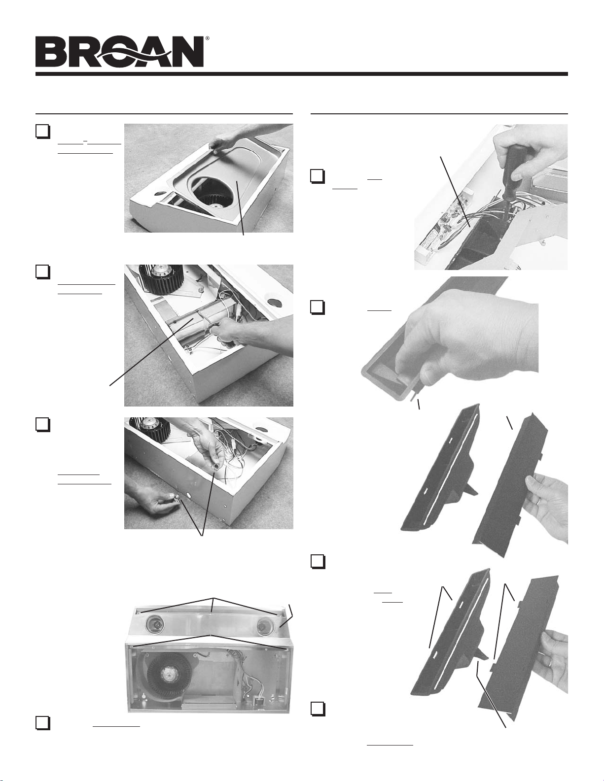
PREPARE THE HOOD
3 Remove
Teflon® is a registered
trademark of DuPont.
4 Remove
5 Remove either
®
Teflon
bottom cover
from hood.
Set cover and
mounting screws
aside.
Damper/Duct
Connector
from inside
the hood. Set
connector
aside - with
mounting
screws and
parts bag.
top or back
wiring knockout and install
approved
Electrical
Cable Clamp.
-coated
DAMPER/
DUCT
CONNECTOR
TEFLON®-COATED BOTTOM COVER
(Held in place with 2 screws)
PREPARE THE HOOD
AIR CHUTE
7 Remove Air
Chute - held in
place with one
(1) screw.
NOTE: Be care-
ful not to disconnect any wires.
8 Remove Baffle
from air chute.
BAFFLE
BAFFLE
ELECTRICAL CABLE CLAMP
Non-Ducted Installation - Skip to Step 15.
(3) #8 SCREWS
The following
Steps (6 thru
14) are for
(2) #8 SCREWS
DUCTED
INSTALLATION
ONLY.
6 Remove Light Panel - held in place with (3) #8 screws
and (2) #8 screws. Disconnect light assembly wire harness
(white connector).
LIGHT
PANEL
9 Rotate baffle. Re-
insert baffle into air
chute (as shown) so
that baffle tabs fit all
the way into slots in
air chute. An audible
“click” will be heard
when fully installed.
This will close off
the air flow through
the non-ducted slots
on top of hood.
10
Re-install air chute, re-connect wire
harness, and replace light panel.
NOTE: Be careful not to trap wires
between support fin and light panel.
SLOTS
TABS
SUPPORT FIN
ALLURE
®
QS3 SERIES
RANGE HOOD
Page 4
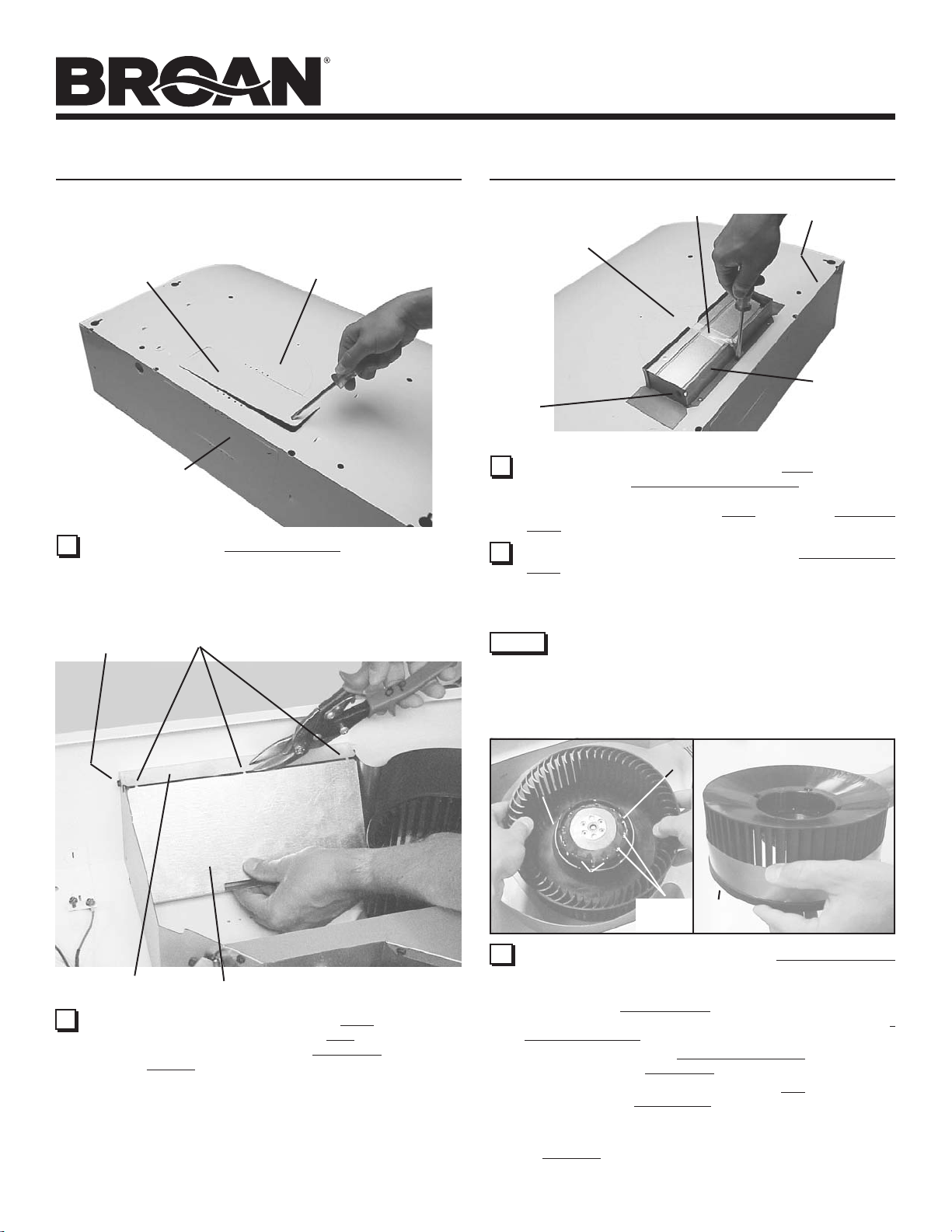
PREPARE THE HOOD
TOP RECTANGULAR
DUCT KNOCKOUT
(Remove for 3¼” x 10”
Vertical & for 7” Round
Discharge)
REAR
RECTANGULAR
DUCT KNOCKOUT
(Remove for 3¼” x 10”
Horizontal Discharge)
11 Remove appropriate Duct Knockout(s) from top or back of
hood.
SCREW
TIES
SEMI-CIRCULAR
DUCT KNOCKOUT
(Remove for 7” Round
Discharge)
PREPARE THE HOOD
UP TO 1”
SIDE-TO-SIDE
ADJUSTMENT
PIVOT
13 3¼” x 10” Ducted Discharge Only: Remove Tape from damper
flap and attach Damper/Duct Connector over knockout
opening with screws removed in Step 4 under “PREPARE
THE HOOD”. Make sure damper Pivot is nearest to Top/Back
Edge of hood.
14 7” Round Ducted Discharge Only: Re-install 7” Round Duct
Plate removed in Step #1 under “PREPARE THE HOOD”.
Install a 7” round damper (purchase separately). Damper
flap must open freely in direction of airflow (away from range
hood).
NOTE
up to ½” on either side of hood center. In extreme off-center
installations, one end of the duct connector may need to be trimmed
to clear the electrical cable clamp.
To accomodate off-center ductwork, the Damper/Duct
Connector can be installed up to 1-inch on either side of
hood center or the 7” Round Duct Plate can be installed
TAPE
TOP/BACK
EDGE
DAMPER/
DUCT
CONNECTOR
(Vertical
discharge
position shown)
METAL STRIP
12 Horizontal Discharge Only: Remove the Plate in front of the
horizontal discharge knockout. Cut the Ties, lift plate out, and
discard plate. DO NOT REMOVE the Metal Strip held in place
with two Screws.
PLATE
RETAINING
RING
15 Non-Ducted Installations Only: Require a Performance Ring
to be attached to the blower wheel.
To install ring:
1. Remove the Blower Wheel by rocking it side to side and
applying a slight force to pull wheel from motor. Remove
Retaining Ring if necessary.
2. Slide the ring onto the Small Diameter End of the wheel
and down to the Stop Edge of the wheel.
3. Reassemble wheel to motor. Make sure Tab on wheel fits
into one of the Motor Slots.
4. Push wheel down until it is locked in place.
5. Check that wheel is properly positioned as shown. Press
Sections into place if necessary. Make sure wheel turns
freely.
BLOWER
WHEEL
SECTIONS
TAB
MOTOR
SLOTS
SMALL DIAMETER
END
RING
STOP
EDGE
ALLURE
®
QS3 SERIES
RANGE HOOD
Page 5
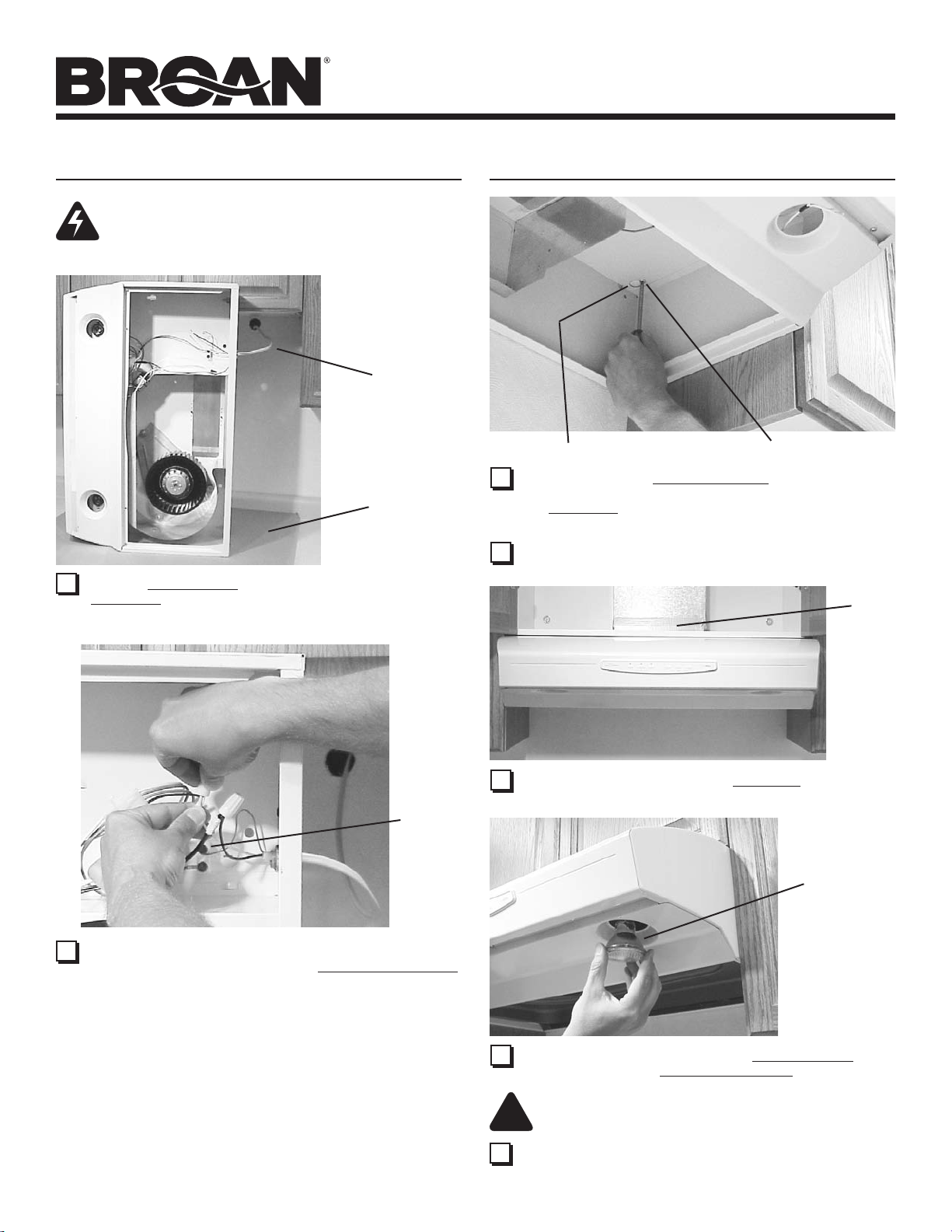
CONNECT WIRING
WARNING: To reduce the risk of electric shock,
make sure power is switched off at the service
panel. Lock or tag service panel to prevent power
from being switched on accidentally.
HOUSE
WIRING
(120 VAC)
CARDBOARD
(Use to protect
cooktop)
1 Connect House Wiring (120 VAC) to hood. Use a piece of
Cardboard to protect the cooktop, if necessary.
INSTALL HOOD
KEYHOLE (4)
1 Hang hood from (4) Mounting Screws. Slide hood towards
wall until mounting screws are engaged in narrow end of
(4) Keyholes. Tighten mounting screws securely. A long
screwdriver works best.
2 Replace bottom cover.
MOUNTING SCREW (4)
DUCT
TAPE
GREEN
GROUND
SCREW
2 Connect house black to hood black wire, house white to hood
white wire, and house ground under Green Ground Screw.
Securely tighten cable clamp onto house wiring.
3 Connect ductwork to hood. Use Duct Tape to make joints
secure and air tight.
PAR20,
50W MAX.
HALOGEN
BULB (2)
- or R16,
40W MAX.
INCANDESCENT
BULB (2)
4 Install (2) PAR20, 50 W Maximum Halogen Bulbs or (2)
R16, 40 W Maximum Incandescent Bulbs. Purchase bulbs
separately.
CAUTION: Bulbs may be hot! Refer to bulb packaging
!
for further information.
5 Replace filters, turn on power at service panel, and test for
proper operation.
 Loading...