

ALLU TM
®
ALLURE TM QS1 SERIES
RANGE HOOD
Page 1
Patent No.:
US D450, 829 S
FOR DOMESTIC
WARNING
TO REDUCE THE RISK OF FIRE, ELECTRIC SHOCK, OR INJURY
TO PERSONS, OBSERVE THE FOLLOWING:
1. Use this unit only in the manner intended by the manufacturer. If
you have questions, contact the manufacturer at the address or
telephone number listed in the warranty.
2. Before servicing or cleaning unit, switch power off at service panel
and lock the service disconnecting means to prevent power from
being switched on accidentally. When the service disconnecting
means cannot be locked, securely fasten a prominent warning
device, such as a tag, to the service panel.
3. Installation work and electrical wiring must be done by a qualified
person(s) in accordance with all applicable codes and standards,
including fire-rated construction codes and standards.
4. Sufficient air is needed for proper combustion and exhausting of
gases through the flue (chimney) of fuel burning equipment to
prevent backdrafting. Follow the heating equipment manufacturer's
guideline and safety standards such as those published by the
National Fire Protection Association (NFPA), and the American
Society of Heating, Refrigeration and Air Conditioning Engineers
(ASHRAE), and the local code authorities.
5. When cutting or drilling into wall orceiling, do not damage electrical
wiring and other hidden utilities.
6. To reduce the risk of fire or electric shock, do not use this range
hood with an additional speed control device.
7. Ducted fans must always be vented to the outdoors.
8. To reduce the risk of fire, use only metal ductwork.
9. Use with approved cord-connection kit only.
10. This unit must be grounded.
TO REDUCETHE RISK OFA RANGETOP GREASE FIRE:
1. Never leave surface units unattended at high settings. Boilovers
cause smoking and greasy spillovers that may ignite. Heat oils
slowly on low or medium settings.
2. Always turn hood ON when cooking at high heat or when cooking
flaming foods.
3. Clean ventilating fans frequently. Grease should not be allowed to
accumulate on fan or filter.
4. Use proper pan size. Always use cookware appropriate for the size
of the surface element.
TO REDUCETHE RiSK OF INJURYTO PERSONS INTHE EVENT
OF A RANGE TOP GREASE FIRE, OBSERVE THE FOLLOWING:*
1. SMOTHER FLAMES with a close-fitting lid, cookie sheet, or metal
tray,then turn off the burner. BE CAREFULTO PREVENT BURNS.
If the flames do not go out immediately, EVACUATE AND CALL
THE FIRE DEPARTMENT.
2. NEVER PICK UPA FLAMING PAN --You may be burned.
3. DO NOT USE WATER, including wet dishcloths or towels - violent
steam explosion will result.
4. Use an extinguisher ONLY if:
A. Youknow you have a Class ABC extinguisher and you already
know how to operate it.
B. The fire is small and contained inthe area where it started.
C. The fire department is being called.
D. You can fight the fire with your back to an exit.
* Based on "Kitchen Fire Safety Tips" published by NFPA.
COOKING ONLY.
CAUTION
1. For general ventilating use only. Do not use to exhaust hazardous
or explosive materials and vapors.
2. To avoid motor bearing damage and noisy and/or unbalanced
impellers, keep drywall spray, construction dust, etc. off power
unit.
3. For best capture of cooking impurities, your range hood should be
mounted so that the top of the hood is 24-30" above the cooking
surface.
4. Please read specification label on product for further information
and requirements.
Installer: Leave this manual with
the homeowner.
Homeowner: Operating and
Cleaning information on page 5.
[_ If hood is to be installed Non-Ducted:
Purchase a set of (2) non-ducted filters from your
local distributor or retailer and attach them to the
aluminum mesh filters.
TABLE OF CONTENTS
This manual is divided into sections as follows:
"PREPARE HOOD LOCATION"
Run ductwork from roof or wall cap, and electrical wiring from
service panel - to installation location
"PREPARETHE HOOD"
Get your hood ready for installation
"CONNECT WIRING"
Make electrical wiring connections to hood
"INSTALL HOOD"
Secure hood to cabinet and ductwork - install bulbs and filters
"OPERATION"
How to usethe hood controls
"CLEANING"
Keep your hood in top working condition
"SERVICE PARTS"
Part numbers and exploded view of hood components
"WARRANTY"
One-year limited warranty and how to contact us
®
ALLURE TM QS1 SERIES
RANGE HOOD
Page 2
PREPARE HOOD LOCATION PREPARE HOOD LOCATION
ROOF CAP
SOFFIT
CABINET_._
31/4'' X 10" or
7" ROUND DUCT HOOD MOUNTING SCREWS (4)
(Forverfical 1315/16"(30"hood)
discharge) 1615/16``(36" hood)
HOUSE WiRiNG
or Back of hood)
t
24" -30" ABOVE
COOKING SURFACE
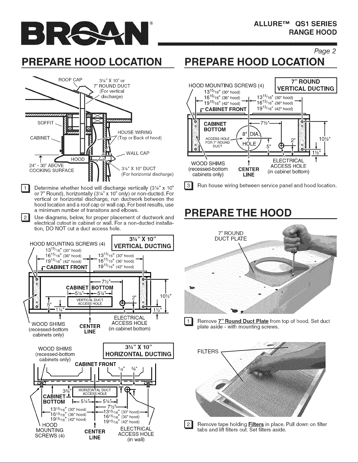
Determine whether hood will discharge vertically (3W' x 10"
53
or 7" Round), horizontally (3W' x 10" only) or non-ducted. For
vertical or horizontal discharge, run ductwork between the
hood location and a roof cap or wall cap. For best results, use
a minimum number of transitons and elbows.
El Use for of ductwork and
diagrams, below, placement
electrical cutout in cabinet or wall. For a non-ducted installa-
tion, DO NOT cut a duct access hole.
HOOD MOUNTING SCREWS (4) VERTICAL DUCTING
1315/16" (30" hood)
1615/16" (36" hood) 1315/16" (30" hood)
1915/16" (42" hood) "--_ _-" 1615/16" (36" hood)
1- CABINET FRONT 1915/16"(42"hood)
) 1 ii _,
!J CABINET BOTTOM
I 4--5 W'---D*-- 5_A'_--_
proper
1 !
i,:1 _ VERTICAL DUCT , 2"
'.!:| 5" .--L ACCESS HOLE
3W' X 10" DUCT
(For horizontal discharge)
31A" X 10"
i 7"ROUND
VERTICALDUCTING i
1 315/16"(30"hood)
(42" hood)
FRONT
CABINET
BOTTOM
ACCESS HOLE
FOR7"ROUND
DUCT
WOOD SHIMS _ ELECTRICAL
(recessed-bottom CENTER (in cabinet bottom)
cabinets only) LiNE
El Run house wiring between service panel and hood location.
(36"hood)
ACCESS HOLE
PREPARE THE HOOD
7" ROUND
DUCT PLATE
WOOD SHIMS
(recessed-bottom
cabinets only)
WOOD SHIMS j 31,4'' X 10" i
(recessed-bottom HORIZONTAL DUCTING
cabinets only)
MOUNTING
SCREWS (4)
t t ELECTRICAL t
CENTER (in cabinet bottom)
LINE
CABINET FRONT
j 1/8" 3_"
ACCESS HOLE
Remove 7" Round Duct Plate from top of hood. Set duct
El
plate aside - with mounting screws.
FILTERS
El Remove Filters in Pull down filter
tabs and lift filters out. Set filters aside.
tape holding place.
on
®
ALLURE TM QS1 SERIES
RANGE HOOD
Page 3
PREPARE THE HOOD
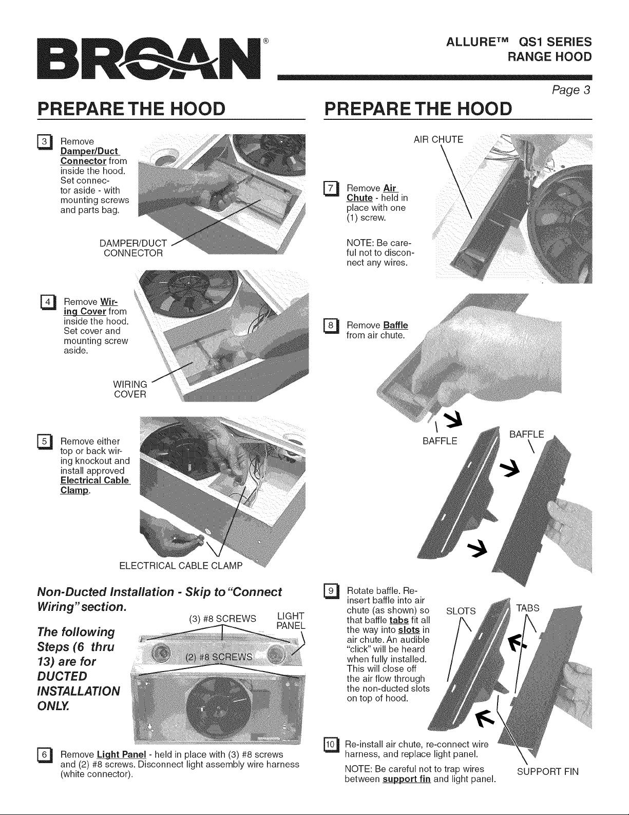
Remove
Damper/Duct
Connector from
inside the hood.
Set connec-
tor aside - with
mounting screws
and parts bag.
DAMPER/DUCT
CONNECTOR
Remove Wir=
El
Cover from
inside the hood.
Set cover and
mounting screw
aside.
WIRING
COVER
PREPARE THE HOOD
AIR CHUTE
Remove Air
53
Chute- held in
place with one
(1) screw.
NOTE: Be care-
ful not to discon-
nect any wires.
El Remove Baffle
from air chute.
Remove either
El
top or back wir-
ing knockout and
install approved
Electrical Cable
Clamp_.
ELECTRICAL CABLE CLAMP
Non-Ducted installation - Skip to "Connect
Wiring"section.
(3) #8 SCREWS LIGHT
The following
Steps (6 thru
13) are for
DUCTED
_!iiii;
iNSTALLATiON
ONLY.
PANEL
Rotate baffle. Re-
Et
insert baffle into air
chute (as shown) so
that baffle tabs fit all
the way into slots in
air chute. An audible
"click" will be heard
when fully installed.
This will close off
the air flow through
the non-ducted slots
on top of hood.
BAFFLE
SLOTS
BAFFLE
\
TABS
El Remove L_ght Panel - held in place with (3) #8 screws
and (2) #8 screws. Disconnect light assembly wire harness
(white connector).
Re-install air chute, re-connect wire
harness, and replace light panel.
NOTE: Be careful not to trap wires
between _ort fin and light panel.
SUPPORT FIN
®
ALLURE TM QS1 SERIES
RANGE HOOD
Page 4
PREPARE THE HOOD
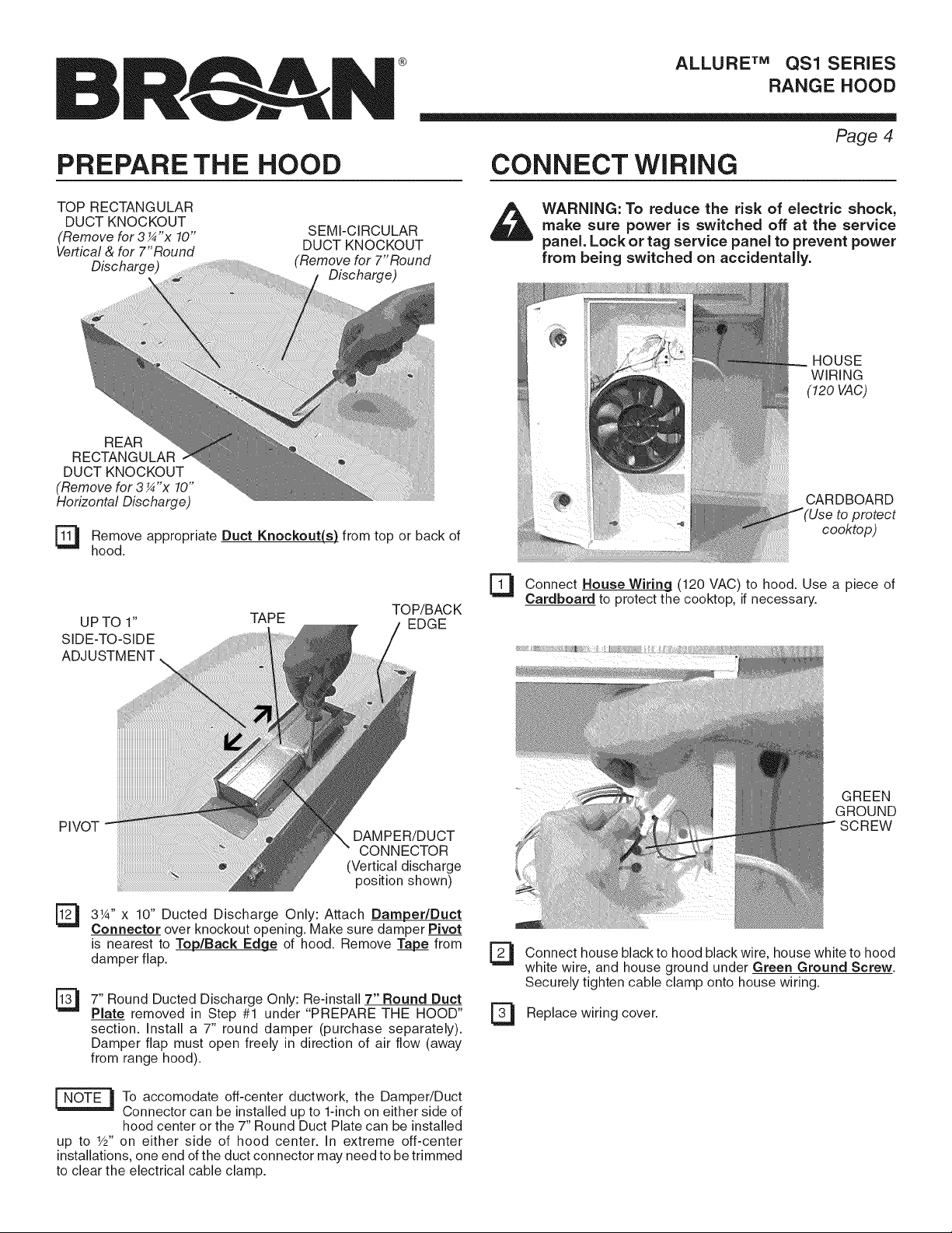
TOP RECTANGULAR
DUCT KNOCKOUT
(Remove for 3¼" x 10"
Vertical & for 7"Round
Discharge)
REAR
RECTANGULAR
DUCT KNOCKOUT
(Remove for 3¼"x 10"
Horizontal Discharge)
[_ Remove appropriate Duct Knockout(s) from or back of
hood.
UPTO 1"
SIDE-TO-SIDE
ADJUSTMENT
TAPE EDGE
SEMI-CIRCULAR
DUCT KNOCKOUT
(Remove for 7"Round
Discharge)
top
TOP/BAC K
CONNECT WIRING
_lb WARNING: To reduce the risk of electric shock,
[_ Connect House to hood. Use of
make sure power is switched off at the service
panel. Lock or tag service panel to prevent power
from being switched on accidentally.
HOUSE
WIRING
(120 VAC)
CARDBOARD
to protect
cooktop)
Wiring (120VAC) a piece
Cardboard to protect the cooktop, if necessary.
PIVOT
31_'' x 10" Ducted Discharge Only: Attach Damper/Duct
Connector over knockout opening. Make sure damper Pivot
is nearest to Top/Back Edg#_ of hood. Remove _ from
damper flap.
7" Round Ducted Discharge Only: Re-install 7" Round Duct
Plate removed in Step #1 under "PREPARE THE HOOD"
section. Install a 7" round damper (purchase separately).
Damper flap must open freely in direction of air flow (away
from range hood).
To accomodate off-center ductwork, the Damper/Duct
Connector can be installed up to 1-inch on either side of
hood center or the 7" Round Duct Plate can be installed
up to Y2" on either side of hood center. In extreme off-center
installations, one end of the duct connector may need to be trimmed
to clear the electrical cable clamp.
DAMPER/DUCT
CONNECTOR
(Vertical discharge
position shown)
GREEN
GROUND
SCREW
El Connect house black to hood black wire, house white to hood
white wire, and house ground under Green Ground Screw.
Securely tighten cable clamp onto house wiring.
Replace wiring cover.

®
ALLURE TM QS1 SERIES
RANGE HOOD
Page 5
iNSTALL HOOD
KEYHOLE
(4)
MOUNTING
SCREW
(4)
Pushing
parts
on
DUCT
TAPE
El Hang hood from (4) Mounting Screws (from bag).
Slide hood towards wall until mounting screws are engaged
in narrow end of (4) Keyholes. Tighten mounting screws
securely.
_DO NOT PUSH ON FAN BLADE. the
blade may cause it to interfere with other hood parts.
NON-DUCTED FILTERS
If hood is to be installed Non-Ducted:
Purchase a set of (2) non-ducted filters from your local distributor or
retailer and attach them to the aluminum mesh filters.
OPERATION
[an tight
Fan: The 3-position rocker switch (on the left) controls the fan. The
left position is low speed, center position is off, and right position is
high speed. An indicator light shows that the fan is on.
Light: The 3-position rocker switch (on the right) controls the lights.
The left position is low light intensity, center position is off, and right
position is high light intensity.
[_ Connect ductwork to hood. Use Duct to make
secure and air tight.
[_ Install (2) PAR20, 50 W Maximum Halogen Bulbs or (2)
R16, 40 W Maximum Incandescent Bulbs. Purchase bulbs
separately.
_b CAUTION: Bulbs be hot! Refer to bulb packaging
for further information.
may
Tape joints
PAR20,
50W MAX.
HALOGEN
BULB (2)
- or-
R16,
40W MAX.
INCANDESCENT
BULB (2)
CLEANING
_bb ARNING: To reduce the risk of electric shock,
Aluminum mesh filters: Clean frequently using hot water and a
mild detergent. Filters are dishwasher safe.
Charcoal filters: Clean filter surfaces frequently with a damp cloth
and a mild detergent. DO NOT immerse filters in water or put in
dishwasher. The special "Clean Sense" feature indicates when the
filter is to be replaced.The blue and yellow strips will blend to green
when it is time to change the filter.The "Clean Sense"feature works
best when facing toward the cooking surface.
To clean hood: Remove filters. Use a damp cloth and a mild deter-
gent to wipe all grease-laden surfaces. Use care when cleaning fan
blade - it must not become bent or misaligned. DO NOT ALLOW
WATER TO ENTER MOTOR. Make sure all surfaces are completely
dry before re-installing filters and restoring power.
Motor is permanently lubricated. Do not oil or disassemble motor.
disconnect from power supply before cleaning.
Replace
El filters and make fan blade turns Turn
power at service panel, and test for proper operation.
sure
freely.
on

SERVICE PARTS
®
ALLURE TM QS1 SERIES
RANGE HOOD
Page 6
KEY NO.
10
11
12
13
14
15
16
17
18
19
2O
Order replacement parts by PART NO.- not by KEY NO.
* Standard hardware - may be purchased locally.
** Not illustrated.
1
2
3
4
6
7
8
9
PART NO.
R680508
R740013
R602017
R561115
R561116
R561117
R561119
R627497
R627498
R627499
R627527
R627575
R607657
R602534
R602533
R680504
R169016
R169002
R99080535
R401647
R401646
R531075
R99420635
99010299
99010300
99010301
Rl11630
R7201731
R7201751
R7201771
R7201732
R7201752
R7201772
R7201734
R7201754
R7201774
R720174
R720176
R720178
R7201735
R7201755
R7201775
R169004
R169010
Rl11626
99010308
99010309
99010310
Replacement parts
can now be ordered
on our website.
Please visit us at
www.Broan.com
DESCRiPTiON
7" Round Duct Plate (includes hardware)
Damper/Duct Connector (includes hardware)
Screw, #8-18 x 1AHex* (2 in package)
Rocker Switch, Almond (2 in package)
Rocker Switch, White (2 in package)
Rocker Switch, Black (2 in package)
Rocker Switch, Biscuit (2 in package)
Nameplate, White
Nameplate, Almond
Nameplate, Stainless
Nameplate, Biscuit
Nameplate, Black
Lens
Screw, 8-18 x 3/8" (2 in package)
Ground Screw (2 req.)
Wiring Cover (includes hardware)
Rivet, Pop .125 dia.
Filter Spring Kit
Motor Mounting Screw (3 each part)
Motor (includes Motor Mounting Kit)
Air Chute Assembly
(includes Key No. 15 & hardware)
Baffle
Fan Blade (includes hairpin clip)
Hairpin Clip
Filter Kit, for 30" Hood (2 per bag)
Filter Kit, for 36" Hood (2 per bag)
Filter Kit, for 42" Hood (2 per bag)
Lamp Socket Harness
Light Panel, White, for 30" Hood
Light Panel,
Light Panel,
Light Panel,
Light Panel,
Light Panel,
Light Panel,
Light Panel,
Light Panel,
Light Panel,
Light Panel,
Light Panel,
Light Pane[,
Light Panel,
Light Panel, Biscuit, for 42" Hood
indicator Light (includes 2 wire nuts and lens)
Light Diode Assembly (includes wire nut)
Wire Harness
Non-Ducted Filter Kit, 30" (2 per bag)
Non-Ducted Filter Kit, 36" (2 per bag)
Non-Ducted Filter Kit, 42" (2 per bag)
White, for 36" Hood
White, for 42" Hood
Almond, for 30" Hood
Almond, for 36" Hood
Almond, for 42" Hood
Black, for 30" Hood
Black, for 36" Hood
Black, for 42" Hood
Stainless, for 30" Hood
Stainless, for 36" Hood
Stainless, for 42" Hood
Biscuit, for 30" Hood
Biscuit, for 36" Hood
15
17 19
WARRANTY
BROAN-NUTONE ONE YEAR LiMiTEDWARRANTY
Broan-NuTone warrants to the original consumer purchaserof its products that
such products will be free from defectsin materialsor workmanship for a periodof
oneyear from the dateof original purchase.THEREARENOOTHERWARRANTIES,
EXPRESSORIMPLIED,INCLUDING,BUTNOT LIMITEDTO,IMPLIEDWARRANTIES
OFMERCHANTABILITYORFITNESSFORA PARTICULARPURPOSE.
Duringthis one-yearperiod,Broan-NuTonewill,at itsoption,repairor replace,without
charge,anyproductor partwhich isfoundtobedefectiveundernormaluseand service.
THIS WARRANTYDOESNOT EXTENDTOFLUORESCENTLAMP STARTERSAND
TUBES.Thiswarranty doesnot cover (a) normal maintenanceand serviceor (b) any
productsor partswhich havebeensubjectto misuse,negligence,accident,improper
maintenanceor repair(otherthan by Broan-NuTone),faultyinstallationor installation
contrary to recommendedinstallationinstructions.
The durationof an impliedwarranty is limited to the one-yearperiod asspecifiedfor
the express warranty. Some statesdo not allow limitation on how long an implied
warranty lasts,so the abovelimitation maynot applyto you.
BROAN-NUTONE'SOBLIGATIONTO REPAIROR REPLACE,AT BROAN-NUTONE'S
OPTION,SHALL BETHE PURCHASER'SSOLEANDEXCLUSIVEREMEDYUNDER
THISWARRANTY.BROAN-NUTONESHALLNOTBELIABLEFORINCIDENTAL,CON-
SEQUENTIALOR SPECIALDAMAGESARISINGOUTOFOR IN CONNECTIONWITH
PRODUCTUSEORPERFORMANCE.Somestatesdonotallowtheexclusionor limitation
of incidentalor consequentialdamages,so theabove limitation maynot applyto you.
Thiswarrantygivesyou specificlegalrights,andyou mayalsohaveother rights,which
vary from stateto state.This warrantysupersedesall prior warranties.
To qualifyfor warranty service,you must (a) notify Broan-NuToneat theaddressor
telephonenumber below,(b) give the modelnumber andpart identificationand (c)
describethe natureof any defectinthe product or part.At the timeof requestingwar-
rantyservice,you must presentevidenceof theoriginal purchasedate.
Broan-NuT0neLLC,926 West StateStreet,Hartford,W153027 (1-800-637-1453)
626974D

®
CAMPANA EXTRACTORA
SERIE QS1 ALLURE TM
EXTRACT0
ALLURE"
PARA COCINAR DOMESTICO SOLAMENTE
P_gina 7
Patent No.:
US D450, 829 S
ADVERTENCIA
PARA REDUCJR EL RIESGO DE INCENDIO, CHOQUE ELECTRICO,
O LESION A PERSONAS, PROCURE LO SIGUJENTE:
1. Utilice esta unidad s61oen la manera prescrita por el fabricante. Si tiene
usted alguna pregunta, comunfquese con el fabricante a la direcci6n
o el tel6fono indicados en la garantia.
2. Antes de efectuar algQn servicio o limpieza, se debe desconectar la
corriente el6ctrica en el armario de circuitos y aseguraflo con Ilave
para evitar que la corriente sea conectada accidentalmente. Cuando no
se puedan inmovilizar los medios de desconexi6n de servicio, pegue
con seguridad un dispositivo de advertencia prominente, tal como una
etiqueta, en el tablero de servicio.
3. Todo trabajo de instalaci6n y cableado el6ctrico debe ser realizado
por personal calificado y de acuerdo con todos los c6digos y normas
pertinentes, incluyendo los c6digos y normas relacionados con con-
strucci6n clasificada para incendio.
4. Aire suficiente es necesario para facilitar la combusti6n adecuada y la
salida apropiada de gases pot la chimenea de la unidad y para evitar
corrientes de aire invertidas. Siga las instrucciones y medidas de se-
guridad del fabricante del equipo y de las sociedades profesionales
de equipos de calentadores y los reglamentos de seguridad locales.
5. A cortar o perforar la pared o el techo, no daSe el cableado el6ctrico
u otros servicios pQblicos ocultos a la vista.
6. Para reducir el riesgo de incendio o de descarga el6ctrica, no utilice
este ventilador con ningQn dispositivo de una control de velocidad de
estado s61ido adicional.
7. Los abanicos con ducto deberAn siempre tenet una salida hacia el
exterior.
8. Para reducir el riesgo de incendio, use s61o ductos de metal.
9. Uso con el kit aprobado del la conexi6n de la cuerda solamente.
10. Esta unidad se debe instalar con tierra efectiva.
PARA REDUCIR EL RIESGO DE UN INCENDIO POR GRASA EN EN
LA ESTUFA:
1. Nunca deje sin atender las unidades de superficie cuando tengan
ajustes altos. Los reboses pueden provocar humo y derrames grasosos
que se pueden incendiar. Caliente lentamente el aceite en un ajuste
bajo o medio.
2. Siempre ENCIENDA la campana cuando cocine con alta temperatura
o cuando cocine alimentos que se puedan incendiar.
3. Limpie con frecuencia los ventiladores. No debe permitir que la grasa
se acumule en el ventilador ni en el filtro.
4. Utilice un sart6n de tamaSo adecuado. Siempre utilice el utensilio
adecuado al tamaSo del elemento de superficie.
PARA REDUCIR EL RIESGO DE LESION A PERSONAS RESULTADO
DE UN INCENDIO DEBIDO A GRASA ACUMULADA EN LAS HORNIL-
LAS, PROCURE LO SIGUIENTE:*
1. AHOGUE LAS LLAMAS con una tapa ajustada o charola de metal,
despu6s apague la hornilla. TENGA CUIDADO A FIN DE EVITAR
QUEMADURAS. Si las llamas no se apagan de inmediato, EVACUE
Y AVlSE A LOS BOMBEROS.
2. NO LEVANTE NUNCA UNA SARTEN QUE ESTE EN LLAMAS - Usted
se podrA quemar.
3. NO UTILICE AGUA, incluyendo toallas de cocina mojadas - puede
resultar una explosi6n de vapor violent&
4. Utilice un extinguidor SOLAMENTE si:
A. Usted sabe que tiene un extinguidor de clas ABC y Io sabe utilizar.
B. El incendio es pequeSo y contenido dentro del Area donde se inici6.
C. Los bomberos han sido avisados.
D. Usted puede combatir el incendio con una salida a su espalda.
* Basado en las recomendaciones para "Seguridad en la Cocina" publi-
cadas pot la NFPA de los EEUU.
PRECAUCION
1. Solamente para uso general de ventilaci6n. No utilice para descargar
matefiales o vapores fiesgosos o explosivos.
2. Para evitar daRos al motor y evitar que las navajas del abanico
emitan mucho ruido o esten fuera de balance, mantenga el motor
libre de pelusa, polvo, etc.
3. Para obtener mejores resultados en la captura de los vapores de la
estufa, el parte superior del extractor debe montarse a entre 45.7 a
60.9 cm sobre las hornillas de la estufa.
4. Por favor lea la etiqueta con las especificaciones del equipo para
otros requisitos y mayor informaci6n.
A la persona que realiza la instalaci6n:
Deje este manual con el dueSo de la casa.
AI dueSo de la casa: Las instrucciones de
operaci6n y limpieza se encuentran en la
p gina 11.
Si la campana se va a instaiar en un sistema sin conductos:
Compre un juego de (2) filtros para sistemas sin conductos en
la tienda distribuidora o minorista de su Iocalidad y m6ntelos
en los filtros de malla de aluminio.
CONTENIDO
Este manual se divide en las siguientes secciones:
"PREPARACION DEL LUGAR DONDE SE VA A INSTALAR LA
CAMPANA"
Tienda de los conductos desde el techo o la tapa de pared, y
haga la conexi6n el6ctrica desde el panel de servicio hasta el sitio
de la instalaci6n.
"PREPARACKDN DE LA CAMPANA"
Prepare la campana para su instalaci6n
"CONEXK)N ELI_CTRICA"
Haga las conexiones el6ctricas hacia la campana
'INSTALACK_)N DE LA CAMPANA"
Asegure la campana en el gabinete y en el sistema de conductos.
Instale focos y filtros.
"OPERACKSN"
C6mo usar los controles de la campana
"LIMPIEZA"
Mantenga su campana en condiciones 6ptimas de funcionamiento
"PIEZAS DE REPUESTO"
NOmero de las piezas y vista ampliada de los componentes de la
campana
"GARANTJA"
Garantia limitada de un aSo y c6mo comunicarse con nosotros

®
CANIPANA EXTRACTORA
SERIE QS1 ALLURE TM
PREPARACION DEL LUGAR DONDE PREPARACION DEL LUGAR P4gina 8
SE VA A INSTALAR LA CAMPANA DONDE SE VA A INSTALAR LA CAMPANA
TAPADETECHO
t CONDUCTO DE
De 45.7 cm a 60.9 cm 8.3 cm x 25.4 cm
SOBRE LA SUPERFICIE (para descarga
PARA COCINAR horizontal)
Determine sJla descarga de la campana va a ser vertical [conducto
53
de 8.3 cm x 25.4 cm (3 ¼"x 10") o conducto redondo de 17.8 cm
(7")], horizontal [s61o conducto de 8.3 cm x 25.4 cm (3 1A"x 10")] o
si es un sistema sin conductos. En el case de descarga vertical u
horizontal, tienda los conductos entre el lugar donde va a instalar
la campana y la tapa de techo o la tapa de pared. Para obtener
los mejores resultados, utilice el nQmero minimo de transiciones L,fJ
y codes.
UtJlJcelos siguientes diagramas para colocar adecuadamente los
conductos y hacer el corte exacto para la conexi6n el6ctrica en
el gabinete o en la pared. En el case de aquellas instalaciones
en sJstemas sin conductos, NO haga ningQn orificio de acceso
para el conducto.
ilSTEIVlA VERTICAL BE CONDUCTOSBE 8.3 25.4 1/4" 10 i
TORNILLOS PARA EL MONTAJE DE LA CAMPANA (4)
35.4cm (campana de 76.2 cm) 35.4 cm (campana de 762 cm)
43.0cm (campana de 91.4 cm)D" 43.0 cm (campana de 91,4 cm)
cm (campana de 106.7 cm) 50.6
FRENTE DEL GABINETE
1
CONDUCTO DE
8.3 cm x 25.4 cm O
REDONDO DE 17.8 cm
• (para descarga vertical)
CABLEADO ELECTRICO
DOM¢STICO (Parte superior
TAPADEPARED
cm x cm
la campana)
x
(3
j SiSTEMAVERTICALDECONDUCTOSiREDONDOSDE17.8 CM(7")
TORNILLOS PARA EL MONTAJE DE LA CAMPANA (4)
35.4cm (campana de 76.2ore) 35.4cm (campana de 76.2 cm)
43.0 cm (campanade91.40m)_43.0Cm!campanade9!:4cm)=
50.6 cm (campana de 106.7cm)l 50.6 cm (campana de 106.7 cm
F FRENTE DEL GABINET_
GABINETE fl_X |
ORIFIC'O DE [jORIFIClO '_ |
_EOOESOuP&%'--_E20.30_J_ i5o.m
\ REDONDODE \, DE DIA.Jl 2 7 cm
_\17._0m "_-!j .... _...."i_I'-
CUNAS DE MADERA
(s61o gabinetes de LJNEA ORIFIOIO DE AGGESO PARA
rondo empotrado) CENTRAL
Haga las eonexiones del cableado dom6stieo entre el panel de
servieio y el lugar donde va a instalar la eampana.
t \ t
LOS GABLES ELEGTRIGOS
(en eJrondo del gabinete)
PREPARACI(SN DE LA CAMPANA
PLACA DEL CONDUCTO
REDONDO DE 17.8 CM (7")
m
; --
19.1 cm- "_
FONDO DELtGABINETE
_13.3 cm-_13.3 cm4
DELCONDUCTOHORIZONTAL
i ORIFIClODEAOOESO I
- 3.2 cm 1
CUNAS DE MADERA
(s61o gabinetes de
fondo empotrado)
_ISTEMA HORIZONTAL DE CONDUCTOS DE 8.3 era x 25.4 era (31/4" x 10"_
CUNAS DE MADERA
(s61o gabinetes de fondo empotrado)
._., FRENTE DEL GABINETE 1,9 cm I
1
t
LINEA ORIFICIO DE ACCESO PARA
CENTRAL
LOS CABLES ELI_CTRICOS
(en el fondo del gabinete)
26.7 cm
t
k, 2=1 X_2 cmI_/ II
! T
I • .IOONOUOTOHORIZONTALII
FONDODEL=-i
o.....T.
_ 95cmOR'F'O'OOEAOOESOO_Lj ,_
I 35.4 cm (campana de 762 cm) I- 35.4 cm icamCp_fa'de 76,2 cm) I 7
I' 43,0 cm (campana de 91,4 cm) T 43.0 cm (campana de 91,4 cm)_l /
50,6cm(campanade1067cm) I 50.6cm(campanade 106,7_1)/
TORNILLOS PARA LJNEA PARALOSCABLES
EL MONTAJE DE CENTRAL ELECTRICOS(en la pared)
LA CAMPANA (4)
t ORIFICIO DEACCESO
Quite la placa del conducto redondo de 17.8 cm (7") de la parte
superior de la campana. Col6quela aparte, con los tornillos de
montaje.
|
FILTROS
Quite la cinta los filtros Tire hacia
de las lengOetas del filtro y s_.quelos levant_.ndolos. Coloque los
filtros a un lade.
que sujeta
en SU
lugar. abajo

®
CAIVlPANA EXTRACTORA
SERIE QS1 ALLURE TM
PBEPABACIONDE
Quite el conector
El
del requlador de
tiro/conector del
interior de la cam-
pana. Ponga aparte
el conector, con los
tornillos de montaje
y la bolsa de piezas.
CONECTOR DEL REGULADOR
DE TIRO/CONDUCTO
Quite la cubierta
El
de la conexi6n
el_ctrica del
interior de la
campana. Ponga
aparte la cubierta
y los tornillos de
montaje.
CUBIERTA DE LA
NEXION ELECTRICA
P_gina 9
LACAMPANA PREPARACIONDELACAMPANA
CONDUCTO
Quite el con-
ducto para aire \
_- (1) tornillo.
- fijado con un
NOTA: Tenga \
cuidado de no
desconectar
ning0n cable.
[_ uite el deflec=
tor del conducto
para aire.
PARA AIRE
\
\
\
E] Quite el agujero
clego para los
cables el6ctricos,
ya sea el superior
o el posterior, e
instale una
para cable el_c-
trico aprobada.
GRAPA DEL CABLE ELECTRICO
Para instalaciones sin conducto, pase a la
secci6n "Conexi6n EI6ctrica"
PANEL DE
Los siguientes (3)#8TORNILLOS
ILUMINACION
pasos.(del 6 al 13)
son SOLO PARA
INSTALAClONES
CON CONDUCTO.
Quite el panel de ilurninaci6n - fijado con .(3) #8 tornillos
El y {2) #8 tornillos. Desconecte el juego del arn6s del alam-
bre (conectador blanco).
DEFLECTOR
DEFLECTOR
Gire el deflec-
rq
tor. Vuelva
a insertar el
deflector en
el conducto
para aire de
manera (seg0n Io dem-
ostrado) que las aletas
entren totalmente en las
ranuras del conducto RANURAS
para aire. Un "tecleo"
audible sera oido
cuando esta insta-
lado completamente.
Esto se cerrara del
aire atraviesa las
ranuras sin con-
ductos encima de
la campana.
[_ Reinstale el
conducto para
aire, vuelva al conectar el
arn6s del alambre, y substituya el
panel de iluminaci6n.
NOTA: Tenga cuidado de que ninguno ALETA DE APOYO
de los cables quede atrapado entre la aleta de apoyo y el
panel de iluminaci6n.
ALETAS

®
CAMPANA EXTRACTORA
SERIE QS1 ALLURE TM
PREPARACIONDELACAMPANA CONEXION ELI CTRICA P gina
AGUJERO CIEGO SUPERIOR DEL
CONDUCTO RECTANGULAR
(Quite en el caso de descargas verti-
cales de 8.3 cmx 25.4 cm
(3 ¼"x 10") o de descargas
con conductos
redondos de
1Z8 cm (7")
AGUJERO CIEGO
POSTERIOR DEL
CONDUCTO RECTAN-
GULAR
(Quite en el caso de descargas
horizontales de 8.3 cm x 25.4
cm (3 ¼"x 10")
[_ Quite aclujero o aqujeros cieclos para
e_ los conductos
apropiados de la parte superior o de la parte posterior de la
campana.
CINTA POSTERIOR
AJUSTE
LATERAL
HASTA DE
2.5 CM ("
PARA CONDUCTO SEMi-
AGUJERO CiEGO _l
CIRCULAR
(Quite en el caso de
descargas con conductos
redondos de 1Z8 cm (7")
BORDE SUPERIOR/
ADVERTENCIA: Para reducir el riesgo de descar=
gas el_ctricas, aseg_rese de apagar el interruptor
de alimentaci6n el_ctrica en el panel de servicio.
BIoquee o rotule el panel de servicio para evitar
que alguien conecte accidentalmente la energia
el_ctrica.
CABLEADO
DOMI2STICO
(120 VCA)
CARTON
(Para proteger
la superficie de
la estufa.)
Haga (120
la conexi6n el6ctrica del suministro dom6stico
VCA) en la campana. Si es necesario, use un pedazo de
cart6n_para proteger la superficie de la estufa.
CONECTOR DEL
PiVOTE
REGULADOR DE
TIRO/CONDUCTO
muestra la posicidn
de descarga vertical.)
S61o para descargas con conductos de 8.3 cm x 25.4 cm (3 X"
El
x 10"): Coloque el conectador del regulador de tiro/conducto
sobre la abertura del agujero ciego. AsegQrese de que elpivote del
regulador de tiro quede Io mAs cerca posible del borde superior/
posterior de la campana. Quite la cinta de la aleta del regulador
de tiro.
[_ S61o para descargas con conducto redondo de 17.8 cm (7"):
Vuelva a instalar la placa del conducto redondo de 1Z8 cm
que quit6 en el paso 1 de la secci6n "PREPARACION DE LA
CAMPANA' Instale un regulador de tiro redondo de 7" (se compra
pot separado). La aleta del regulador se debe abfir libremente en
direcci6n del flujo de aire (en sentido contrafio a la campana de
la estufa).
Para acomodar los conductos descentrados, el conector del
regulador de tiro/conducto se pueden instalar a una distancia
cualquier lade o la placa del conducto redondo de 1Z8 cm (7") se pueden
instalar a una distancia hasta de 1.3 cm (W') desde el centre de la campana
hacia cualquier lade. En instalaciones exc6ntricas extremas, un extreme del
conector de regulador de conducto puede necesitar ser cortado al clare la
grapa para cable el@trice.
hasta de 2.5 cm (1") desde el centre de la campana hacia
Conecte el cable negro del suministro dom6stico con el cable
U
negro de la campana, el cable blanco del suministro dom6stico
con el cable blanco de la campana y la conexi6n a tierra del
suministro dom6stico debajo del tornillo verde de conexi6n
a tierra. Apriete fijamente una grapa para cable el6ctrico a
cableado dom6stico.
Vuelva a instalar la cubierta de la conexi6n el6ctrica.
P2J
TORNILLO
DE
CONEXION
ATIERRA

INSTALAClON
®
CANIPANA EXTRACTORA
SERIE QS1 ALLURE TM
P_gina 11
DE LA CAMPANA FILTROS SIN CONDUCTOS
ORIFICIO
CALLAVE
(4)
TORNILLO
DE MON-
TAJE
(4)
Cuelgue la campana de los (4) orificios de montaj#_ (que se
53
encuentran en la bolsa de piezas). Deslice la campana hacia
la pared hasta que losorificios de montaje queden conectados
en el extremo angosto de los (4) orificios tipo bocallave.
Apriete fijamente los tornillos de montaje.
NO EMPUJE EN LA HOJA DEL VENTILADOR.
El empujar en la aspa del ventilador puede hacerla interferir con
otras piezas de la capilla.
CINTA
PARA
CON-
DUCTOS
BA-
[_ Si campanasevaa en un
la instalar sistema sin conductos:
Compre un juego de (2) filtros para sistemas sin conductos
en la tienda distribuidora o minorista de su Iocalidad y sujete
a los filtros de malla de alumino.
OPERAClON
Ventilador: El interruptor oscilante de 3 posiciones (de la izquierda)
controla elventilador. La posici6n hacia la izquierda es lavelocidad
baja, la posici6n central es apagado y la posici6n hacia la derecha
es la velocidad alta. Una luz indicadora se ilumina cuando el ven-
tilador esta encendido.
Luz: El interruptor oscilante de 3 posiciones (de laderecha) controla
las luces. La posici6n de la izquierda es luz de baja intensidad, la
posici6n central es apagado y la posici6n a la derecha es luz de
alta intensidad.
LIMPIEZA
[_ Conecte el sistema de conductos en la Use cinta
para conductos para fijar y sellar las uniones.
campana.
DE HALOGE-
NO
PAR20,
50W MAX. (2)
- O -
R16, 40W MAX.
BULBOS
INCANDESCENTES
(2)
[_ Instale (2) focos de hal6geno PAR20, de 50W maximo o (2)
R16 bulbos incandescentes del mAximo de 40W. Compre
los bulbos por separado.
_ PRECAUCION: iLos bulbos pueden set calientes!
El Vuelva a colocar los filtros, asegQrese de la hoja de
Refiera a la empaqueta del bulbo para la informaci6n
adicional.
Y que
ventilador gira libremente. Conecte la energia en el panel de
servicio y revise el funcionamiento adecuado de la campana.
_ ADVERTENCIA: Para reducir el riesgo de una
Filtros de malla de aluminio: Limpie frecuentemente los filtros
con agua caliente y un detergente suave. Los filtros se pueden
lavar en lavaplatos.
Filtros de carb6n: Limpie frecuentemente los filtros con agua ca-
liente y un detergente suave. NO sumerja los filtros en agua ni los
coloque en el lavaplatos. La caracteristica especial "Clean Sense"
(Detecci6n de limpieza) indica cuando se debe reemplazar el filtro.
Las lineas azules y amarillas se combinaran produciendo un color
verde cuando sea el momento de cambiar el filtro. La caracteristica
"Clean Sense" funciona mejor cuando se coloca orientada hacia la
superficie para cocinar.
Para limpiar la campana: Quite los filtros. Use un paso h_medo y
un detergente suave para limpiar las superficies con grasa. Tenga
cuidado cuando limpie la hoja del ventilador. No se debe doblar ni
desalinear. NO PERMITA LA ENTRADA DE AGUA EN EL MOTOR.
AsegOrese de que todas las superficies est6n completamente secas
antes de volver a colocar los filtros y conectar la energia el6ctrica.
El motor esta permanentemente lubricado. No lubrique ni desmonte
el motor.
descarga el_ctrica, desconecte el suministro
el_ctrico antes de limpiar la unidad.

®
CAIVIPANA EXTRACTORA
SERIE QS1 ALLURE TM
PIEZAS DE SERVlCIO
CLAVENO.
1
2
3
4
6
7
8
9
10
11
12
13
14
15
16
17
18
19
2O
Pida piezasde repuestodando como referenciael N°. DEPIEZA, noel N°. DE CLAVE
* Herrajeest_ndar: se puede comprar en la ferreteria de la Iocalidad.
** No ilustrado.
PEZA NO.
R680508
R740013
R602017
R561115
R561116
R561117
R561119
R627497
R627498
R627499
R627527
R627575
R607657
R602534
R602533
R680504
R169016
R169002
R99080535
R401647
R401646
R531075
R99420635
R531075
99010300
99010301
Rl11630
R7201731
R7201751
R7201771
R7201732
R7201752
R7201772
R7201734
R7201754
R7201774
R720174
R720176
R720178
R7201735
R7201755
R7201775
R169004
R169010
Rl11626
99010308
99010309
99010310
DESCRIPCION
Placapara conducto redondo de 17.8 cm (incluye herraje
Conector de regulador detiro/conducto (incluye herraje)
Tornillo, #8-18 x 1/4 hexagonal* (2 enel paquete)
Interruptor oscilante,color almendra (2 en el paquete)
Interruptor oscilante,color blanco (2 en el paquete)
Interruptor oscilante,color negro (2en el paquete)
Interruptor oscilante,cer_mica (2 enel paquete)
Placade identificaci6n, color blanco
Placade identificaci6n, color almendra
Placade identificaci6n, inoxidable
Placade identificaci6n, cer_mica
Placade identificaci6n, color negro
Lentes
Tornillo, 8-18 x 3/8" (2 enel paquete)
Tornillo deconexi6n a tierra
Cubierta parala conexi6n el_ctrica (incluye herraje)
Remache,.125 dia.
Juego de resorte defiltro
Tornillo demontaje del motor (3 cadapieza)
Motor (incluye juego de montaje de motor)
Juegodeconducto paraaire(incluyeclavesno. 15y herrajel
Deflector
Hojadel ventilador (incluye sujetador de horquilla)
Sujetadorde horquilla
Juego de filtros, para campanas de 76.2 cm (2 pot bolsa
Juego de filtros, para campanas de 91.4 cm (2 por bolsa
Juego de filtros, paracampanas de 106.7 cm (2 por bolsa
Cableadopreformado para el recept_culo del foco
Panelde iluminaci6n, blanco, paracampanas de 76.2 cm
Panelde iluminaci6n, blanco, paracampanas de 91.4 cm
Panelde iluminaci6n, blanco,para campanasde 106.7crr
Paneldeiluminaci6n, almendra,para campanasde 76.2 crr
Paneldeiluminaci6n, almendra,para campanasde 91.4 crr
Paneldeiluminaci6n, almendra,paracampanasde106.7 crr
Panelde iluminaci6n, negro, para campanasde 76.2 cm
Panelde iluminaci6n, negro, para campanasde 91.4 cm
Panelde iluminaci6n, negro, para campanasde 106.7crr
Paneldeiluminaci6n, inoxidable,paracampanasde76.2 crr
Paneldeiluminaci6n, inoxidable,paracampanasde91.4 crr
Paneldeiluminaci6n,inoxidable,paracampanasde106.7 crr
Paneldeiluminaci6n, cer_mica,para campanasde 76.2 crr
Paneldeiluminaci6n, cer_mica,para campanasde 91.4 crr
PaneldeiluminaciOn,cerAmica,paracampanasde106.7 crr
Luz indicadora (incluye 2 tuercas de alambres y lentes)
Montaje de diodo de la luz (incluye tuerca dealambre)
Arn_s de alambres
Juego de filtros para sin conductos, 76.2 cm (2por bolsa
Juego de filtros para sin conductos, 91.4 cm (2por bolsa
Juego defiltros parasin conductos, 106.7cm (2 por bolsa
Las piezas de recambio
se pueden ahora pedir en
nuestro Web site.
Visitenos por favor en
www.Broan.com
P_gina 12
3
/ _ o/
I
1 5
15
/
14
3
\
2
7
8 Iz
//I
13
• --18
/
17
19
GARANTIA
GARANTIA BROAN-NUTONE UMITADA POR UN ANO
Broan-NuTone garantiza al consumidor comprador original de sus productos que
dichos productos carecer_.n de defectos en materiales o en mano de obra por un
periodo de un aho a partir de la fecha original de compra. NO EXISTEN OTRAS
GARANTIAS, EXPLICITAS O IMPLICITAS, INCLUYENDO, PERO NO LIMITADAS
A, GARANTIAS IMPLICITAS DE COMERCIALIZACION O APTITUD PARA UN
PROPOSITO PARTICULAR.
Durante el periodo de un aho, y a su propio criterio, Broan-NuTone reparar_, o reem-
plazara, sin costo alguno cualquier producto o pieza que se enouentre defeotuosa
bajo condiciones normales de servicio y uso.
ESTA GARANTIA NO SE APLICA A TUBOS Y ARRANCADORES DE LAMPARAS
FLUORESCENTES. Esta garantia no cubre (a) mantenimiento y servicio normales
o (b) oualquier producto o piezas que hayan sido utilizadas de forma err6nea, negli-
gente, que hayan oausado un accidente, o que hayan sido reparadas o mantenidas
inapropiadamente (pot otras compaKiias que no sean Broan-NuTone), instalaoiOn
defectuosa, o instalaoiOn contraria a las instrucciones de instalaoiOn recomendadas.
La duraci6n de cualquier garantia implicita se limita a un periodo de un afio como
se especifica en la garantia expresa. Algunos estados no permiten limitaciones en
cuanto al tiempo de expiraci6n de una garantia implicita, pot Ioque la limitaci6n antes
mencionada puede no aplicarse a usted.
LA OBLIGACION DE BROAN-NUTONE DE REPARAR O REEMPLAZAR, SIGUIEN-
DO EL CRITERIO DE BROAN-NUTONE, DEBERA SER EL UNICO Y EXCLUSIVO
RECURSO LEGAL DEL COMPRADOR BAJO ESTA GARANTIA. BROAN NO SERA
RESPONSABLE POR DAINOS INCIDENTALES, CONSIGUIENTES, O POR DAi_OS
ESPECIALES QUE SURJAN A RAIZ DEL USO O DESEMPEi_O DEL PRODUCTO.
Algunos estados no permiten la exolusi6n o limitaci6n de dahos incidentales o con-
siguientes, por Ioque la limitaci6n antes mencionada puede no aplicarse a usted.
Esta garantia le proporciona derechos legales espeoificos, y usted puede tambi6n
tener otros derechos, los cuales varian de estado a estado. Esta garantia reemplaza
todas las garantias anteriores.
Para calificar en la garantia de servicio, usted debe (a) notifioar a Broan-NuTone al
domicilio o numero de tel6fono naabajo, (b) dar eln0mero del modelo y la identificaci6n
de la pieza, y (c) describir la naturaleza de oualquier defecto en el produoto o pieza.
En el momento de solicitar servioio cubierto pot la garantia, usted debe de presentar
evidencia de la fecha original de compra.
Broan-NuTone LLC., 926 West State Street, Hartford, Wl 53027 (1-800-637-1453)
I
I
/
7
626974D
 Loading...