

Page 1
!
!
!
POWER
MODULE
PM390HS SERIES
READ AND SAVE THESE INSTRUCTIONS
INTENDED FOR DOMESTIC COOKING ONLY
WARNING
TO REDUCE THE RISK OF FIRE, ELECTRIC SHOCK, OR INJURY
TO PERSONS, OBSERVE THE FOLLOWING:
1. Use this unit only in the manner intended by the manufacturer. If you
have questions, contact the manufacturer at the address or telephone number listed in the warranty.
2. Before servicing or cleaning unit, switch power off at service panel
and lock service panel to prevent power from being switched on
accidentally. When the service disconnecting means cannot be
locked, securely fasten a prominent warning device, such as a tag,
to the service panel.
3. Installation work and electrical wiring must be done by a qualified
person(s) in accordance with all applicable codes and standards,
including fire-rated construction codes and standards.
4. Sufficient air is needed for proper combustion and exhausting of
gases through the flue (chimney) of fuel burning equipment to prevent backdrafting. Follow the heating equipment manufacturer’s
guidelines and safety standards such as those published by the National Fire Protection Association (NFPA), and the American Society for Heating, Refrigeration and Air Conditioning Engineers
(ASHRAE), and the local code authorities.
5. When cutting or drilling into wall or ceiling, do not damage electrical
wiring and other hidden utilities.
6. Ducted fans must always be vented to the outdoors.
7. Do not use this unit with any separate solid-state speed control device.
8. To reduce the risk of fire, use only metal ductwork.
9. This unit must be grounded.
TO REDUCE THE RISK OF A RANGE TOP GREASE FIRE:
A. Never leave surface units unattended at high settings. Boilovers cause
smoking and greasy spillovers that may ignite. Heat oils slowly on
low or medium settings.
B. Always turn hood ON when cooking at high heat or when flambeing
food (i.e. Crepes Suzette, Cherries Jubilee, Peppercorn Beef
Flambe’).
C. Clean ventilating fans frequently. Grease should not be allowed to
accumulate on fan or filter.
D. Use proper pan size. Always use cookware appropriate for the size
of the surface element.
CAUTION
1. To reduce risk of fire and to properly exhaust air, be sure to duct air
outside. Do not vent exhaust air into spaces within walls or ceilings
or into attics, crawl spaces, or garages.
2. Take care when using cleaning agents or detergents.
3. Avoid using food products that produce flames under the Range
Hood.
4. For general ventilating use only. Do not use to exhaust hazardous
or explosive materials and vapors.
5. To avoid motor bearing damage and noisy and/or unbalanced
impellers, keep drywall spray, construction dust, etc. off power unit.
6. Your hood motor has a thermal overload which will automatically
shut off the motor if it becomes overheated. The motor will restart
when it cools down. If the motor continues to shut off and restart,
have the hood serviced.
7. For best capture of cooking impurities, the bottom of the hood should
be a minimum of 24" and a maximum of 30" above the cooking
surface.
8. Two installers are recommended.
9. This product is equipped with a thermostat which may start blower
automatically. To reduce the risk of injury and to prevent power
from being switched on accidentally, switch power off at service
panel and lock or tag service panel.
10. Please read specification label on product for further information
and requirements.
WARNING
TO REDUCE THE RISK OF INJURY TO PERSONS IN THE EVENT
OF A RANGE TOP GREASE FIRE, OBSERVE THE FOLLOWING:*
1. SMOTHER FLAMES with a close-fitting lid, cookie sheet, or metal
tray, then turn off the burner. BE CAREFUL TO PREVENT BURNS.
If the flames do not go out immediately, EVACUATE AND CALL
THE FIRE DEPARTMENT.
2. NEVER PICK UP A FLAMING PAN - You may be burned.
3. DO NOT USE WATER, including wet dishcloths or towels - violent
steam explosion will result.
4. Use an extinguisher ONLY if:
A. You know you have a Class ABC extinguisher and you already
know how to operate it.
B. The fire is small and contained in the area where it started.
C. The fire department is being called.
D. You can fight the fire with your back to an exit.
* Based on “Kitchen Fire Safety Tips” published by NFPA.
1
Page 2
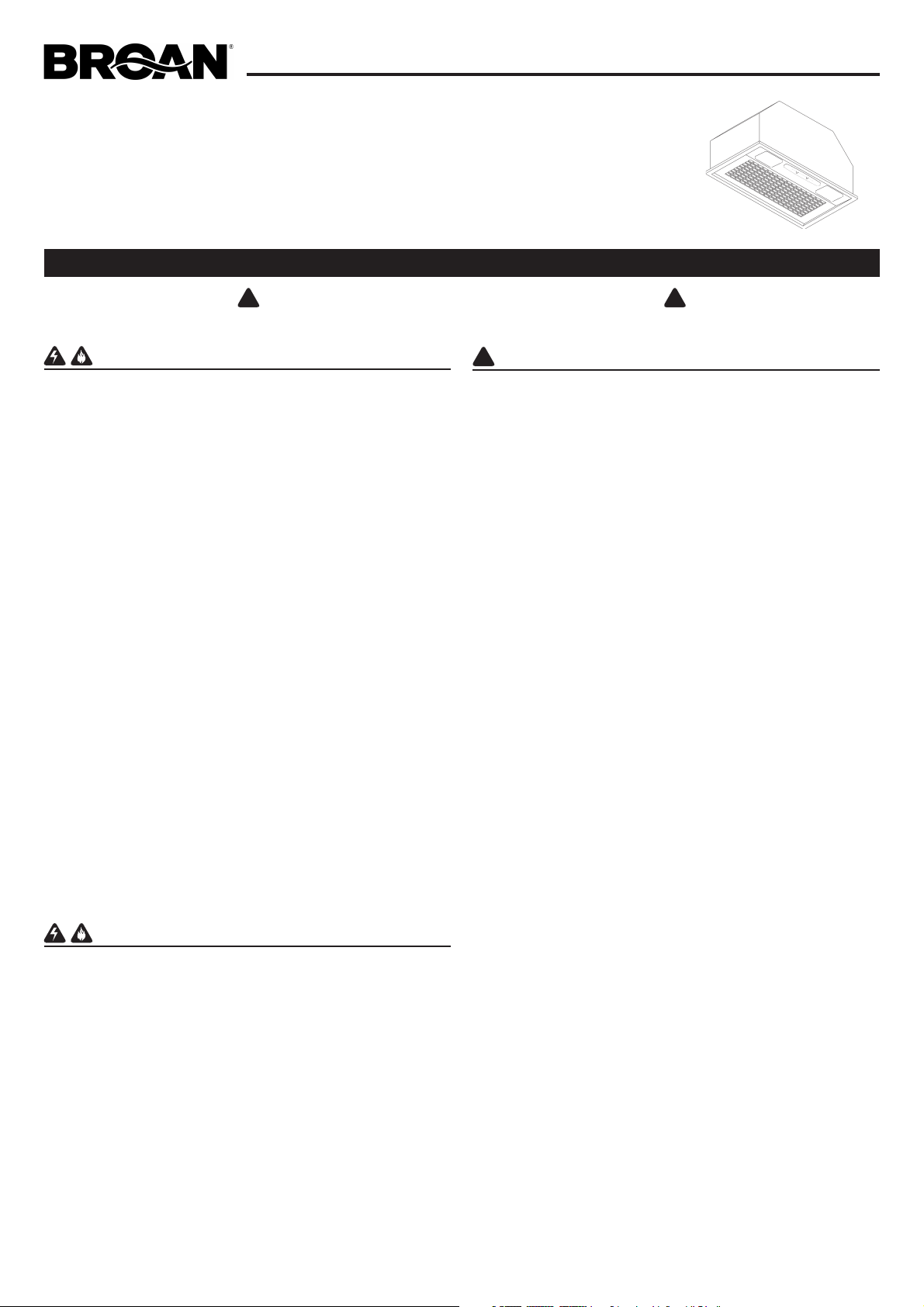
INSTALL THE DUCTWORK
NOTE: To reduce the risk of fire, use only metal ductwork.
1. Decide where the ductwork will run between the hood and the
outside.
2. A straight, short duct run will allow the hood to perform most
efficiently.
3. Long duct runs, elbows, and transitions will reduce the performance
of the hood. Use as few of them as possible. Larger ducting may
be required for best performance with longer duct runs.
4. Install a roof or wall cap. Connect round metal ductwork to cap
and work back towards hood location. Use duct tape to seal the
joints between ductwork sections.
ROOF CAP
ROUND
DUCT
WALL
CAP
POWER
MODULE
24” TO 30” ABOVE
COOKING SURFACE
6”
ROUND
ELBOW
FIG. 1
INSTALL THE HOOD
NOTE: the hood has to be installed, inside the cabinet, at minimum
1” from the rear wall cabinet and at 3” from the front wall cabinet.
The internal height of cabinet has to be minimum 16”.
The hood should be mounted centered over the cook top burners.
B
min 7/16”
max 13/16”
FIG. 4 FIG. 5
CONNECT DUCTWORK
Ducted Configuration
1. Take the damper and assemble it onto the hood’s discharge
opening, pressing slightly.
2. Use 6" round metal duct to connect the discharge collar on the
hood to the ductwork above.
3. Use duct tape to make all joints secure and air tight.
Non-Ducted Recirculation Configuration
1. Connect a 6” round metal duct to the discharge opening so
that the air is sent outside the cabinet and sent back into the
room.
2. Use duct tape to make all joints secure and air tight.
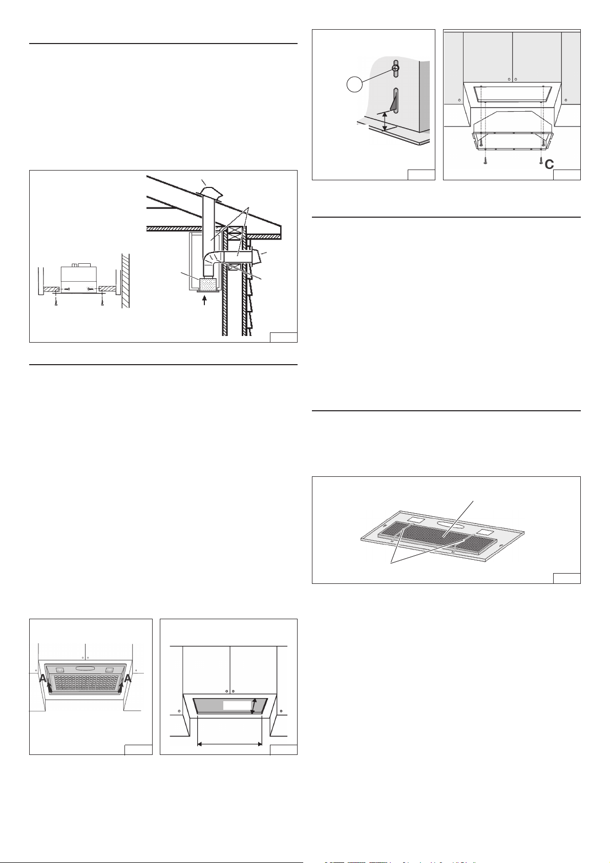
NON-DUCTED RECIRCULATION FILTER
INSTALLATION
1. Remove the grid by moving the 2 slide fasteners “A” forward (Fig.2).
2. Cut a hole in the bottom of the cabinet, using the dimensions shown
(Fig. 3).
3. Adjust the position of the clasping side spring by means of the
proper “B” screw according to the thickness of the bored panel to
which it is going to be anchored (Fig. 4).
4. NOTE: For installations where the Power Pack is less than 30”
above cook top, it is recommended that the Power Pack be
mounted into a metal liner or non-combustible material. This will
allow easier cleaning and provide protection to the cabinetry.
5. Insert the hood in the cabinet and lock it by means of the side
spring.
6. Insert the hood in the cabinet and secure with the (4) “C” mounting
screws 3.2x13mm (Fig. 5). For alternative side fixing use M4x15mm
screws with washers and nuts.
7. In the Non-Ducted Recirculation Configuration, install the Nonducted recirculation Filter before replacing the grid (see section
“Non-ducted recirculation filter installation”).
8. Replace the grid.
CUT A HOLE IN THE BOTTOM OF
THE CABINET
10-1/4”
1. Remove the metal wires (Fig. 9) and discard them.
2. Install the Non-ducted recirculation filter over the grease filter and
secure it with the metal wires supplied with the Non-ducted
recirculation Filter (Fig. 6).
NON-DUCTED
RECIRCULATION FILTER
METAL WIRES
FIG. 6
19-1/2”
FIG. 2 FIG. 3
2
Page 3
WIRING
Note: This range hood must be properly grounded.
The unit should be installed by a qualified electrician in accor-
dance with all applicable national and local electrical codes.
GROUNDING INSTRUCTIONS
This appliance must be grounded. In the event of an electrical short
circuit, grounding reduces the risk of electric shock by providing an
escape wire for the electric current. This appliance is equipped
with a cord having a grounding wire with a grounding plug. The
plug must be plugged into an outlet that is properly installed and
grounded.
WARNING - Improper grounding can result in a risk of electric shock.
Consult a qualified electrician if the grounding instructions are not
completely understood, or if doubt exists as to whether the appliance
is properly grounded.
Do not use an extension cord. If the power supply cord is too short,
have a qualified electrician install an outlet near the appliance.
Position the electrical outlet at a maximum distance of 33-7/16” (85
cm) from where the lead exits from the hood (see illustration alongside).
Fit the plug into the outlet.
MAINTENANCE
ALWAYS SWITCH OFF THE ELECTRICITY SUPPLY BEFORE
CARRYING OUT ANY OPERATIONS ON THE APPLIANCE.
Grease Filter
The grease filter should be cleaned frequently. Use a warm detergent
solution. Grease filter is dishwasher safe.
To remove the grease filter: remove the grid by moving the 2 slide
fasteners “A” (Fig. 2); remove the metal wires and then the grease
filter (Fig. 9).
METAL WIRES
GREASE FILTER
FIG. 9
33-7/16”
(85cm)
FIG. 7
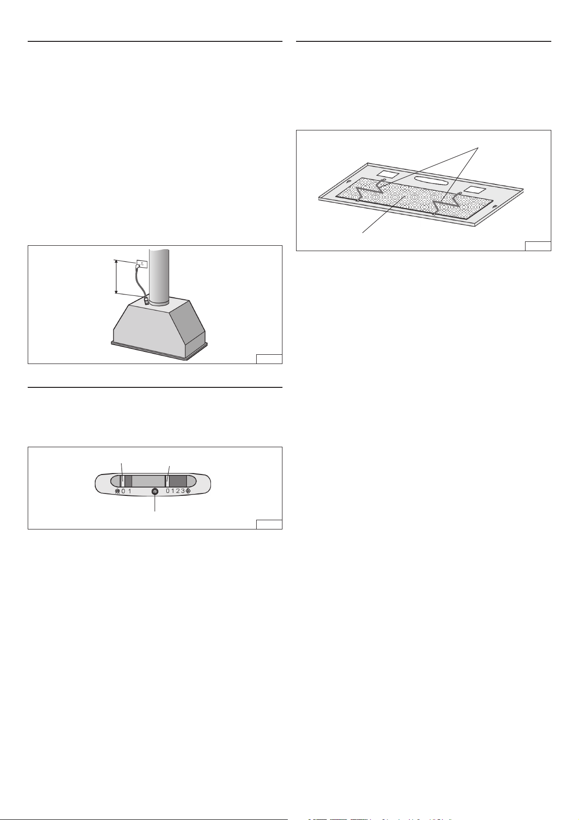
OPERATION
Controls
The light switch turns the lamps on and off.
The blower switch: makes it possible to select the motor operating
speed. Position 0: motor off.
The pilot lamp lights up whenever the blower is on.
LIGHT
SWITCH
HEAT SENTRY™
Your hood is equipped with a HEAT SENTRY™ thermostat.
This thermostat is a device that will turn on or speed up the blower
if it senses excessive heat above the cooking surface.
1) If blower is OFF - it turns blower ON to HIGH speed.
2) If blower is ON at a lower speed setting - it turns blower up to
HIGH speed.
When the temperature level drops to normal, the blower will return
to its original setting.
BLOWER
SWITCH
PILOT LAMP
FIG. 8
Non-Ducted Recirculation Filter
The Non-Ducted Recirculation filter should be changed every 6
months.
To remove the Non-Ducted Recirculation filter:
1. Remove the grid by moving the 2 side fasteners “A” (Fig. 2).
2. Remove the metal wires (Fig. 6) and replace the Non-ducted
recirculation Filter.
Cleaning
Occasional care will help preserve its fine appearance.
• Clean with warm water and mild detergent only.
• Follow all cleaning by rinsing with clear water.
• Wipe dry with clean, soft cloth.
Light bulbs
This range hood requires two 40-Watt light bulbs (not included).
To change bulbs:
1. Remove the grid by moving the 2 slide fasteners (A).
2. Replace with light bulbs of the same type (MAX 40W, 120V,
Candelabra Base Bulb). CAUTION: BULB MAY BE HOT!
WARNING
The HEAT SENTRY thermostat can start the blower even if
the hood is turned OFF. When this occurs, it is impossible to
turn the blower OFF with its switch. If you must stop the
blower, do it from the main electrical panel.
3
Page 4

SERVICE PARTS
KEY NO. PART NO. DESCRIPTION
4 B03295038 Side Fastener
5 B03127682 Grid
6 B02011013 Spring
9 B08087922 Grease Filter
14 B02300233 Condenser
27 B02011155 Metal Wires
28 B02300280 Lampholder
29 B03293051 Light Fitting
37 B02300787 Heat Sentry
45 BW0000043 Blower
48 B02310203 Motor
49 B03295000 Blower Wheel
60 B02300249 Feeder Cable
86 B08088378 Damper
134 B03295039 Grid Stop
145 B032920170 Wiring Box
146 B032920180 Wiring Box Cover
147 BR2300132 Terminal Block
151 B032920200 Wire Clamp
152 B03292200 Wire Clamp
165 B03294780 Controls Box
165 B03295008 Box Condenser
166 B08086668 Heat Sentry Board
196 BE3348672 Reflector
202 B03294779 Runner Wires
222 B03295040 Control Box Cover
223 B03295042 Blower Switch
228 B08086285 Controls Board
229 B03201014 Pilot Lamp
241 B03295041 Light Switch
472 BE3344843 Controls Bracket
AQI B06108860 Switch box Assembly
- - “40 Watt Max.Candelabra
- B08999040 Non-Ducted Filter Kit
(Included Key No. 165, 228,
28, 222, 152, 241, 223, 202,
229)
Bulbs not included”
(purchased separately)
WARRANTY
BROAN-NUTONE LLC ONE YEAR LIMITED WARRANTY
Broan-NuTone LLC warrants to the original consumer purchaser of its products that such products will be free from defects in
materials or workmanship for a period of one year from the date of original purchase. THERE ARE NO OTHER WARRANTIES,
EXPRESS OR IMPLIED, INCLUDING, BUT NOT LIMITED TO, IMPLIED WARRANTIES OR MERCHANT ABILITY OR FITNESS
FOR A PARTICULAR PURPOSE.
During this one-year period, Broan-NuTone LLC will, at its option, repair or replace, without charge, any product or part which is
found to be defective under normal use and service.
THIS WARRANTY DOES NOT EXTEND TO FLUORESCENT LAMP STARTERS, TUBES, HALOGEN AND INCANDESCENDT
BULBS. This warranty does not cover (a) normal maintenance and service or (b) any products or parts which have been subject
to misuse, negligence, accident, improper maintenance or repair (other than by Broan-NuTone LLC), faulty installation or installation
contrary to recommended installation instructions.
The duration of any implied warranty is limited to the one-year period as specified for the express warranty. Some states do not
allow limitation on how long an implied warranty lasts, so the above limitation may not apply to you.
BROAN-NUTONE LLC’S OBLIGATION TO REPAIR OR REPLACE, AT BROAN-NUTONE LLC’S OPTION, SHALL BE THE
PURCHASER’S SOLE AND EXCLUSIVE REMEDY UNDER THIS WARRANTY. BROAN-NUTONE LLC SHALL NOT BE LIABLE
FOR INCIDENTAL, CONSEQUENTIAL OR SPECIAL DAMAGES ARISING OUT OF OR IN CONNECTION WITH PRODUCT USE
OR PERFORMANCE. Some states do not allow the exclusion or limitation of incidental or consequential damages, so the above
limitation or exclusion may not apply to you.
This warranty gives you specific legal rights, and you may also have other rights, which vary from state to state. This warranty
supersedes all prior warranties.
To qualify for warranty service, you must (a) notify Broan-NuTone LLC at the address stated below or telephone: 1-800-637-1453,
(b) give the model number and part identification and (c) describe the nature of any defect in the product or part. At the time of
requesting warranty service, you must present evidence of the original purchase date.
Broan-NuTone LLC. 926 West State Street, Hartford, WI 53027 (1-800-637-1453)
NuTone, Inc., 4820 Red Bank Road, Cincinnati, OH 45227 (1-800-543-8687)
Broan-NuTone Canada, Inc. 1140 Tristar Drive, Mississauga, Ontario, L5T 1H9 (1-888-882-7626)
Page 5

MODULE DE HOTTE
!
!
!
ENCASTRABLE
LISEZ ET CONSERVEZ CES INSTRUCTIONS
POUR UTILISATION DOMESTIQUE SEULEMENT
SÉRIE PM390HS
AVERTISSEMENT
AFIN DE RÉDUIRE LES RISQUES D’INCENDIE, D’ÉLECTROCUTION
OU DE BLESSURES CORPORELLES, OBSERVEZ LES
INSTRUCTIONS SUIVANTES :
1. N’utilisez cet appareil que de la façon prévue par le constructeur.
Si vous avez des problèmes, contactez le fabriquant à l’adresse ou
au numéro de téléphone indiqués dans la garantie.
2. Avant de nettoyer ou de réparer l’appareil, coupez le courant au
panneau d’alimentation et verrouillez-en l’accès afin d’éviter sa
remise en marche accidentelle. Si le panneau d’alimentation ne peut
être verrouillé, apposez un avertissement bien en évidence, par
exemple une étiquette de couleur vive.
3. Les travaux d’installation et de raccordement électrique doivent être
effectués par du personnel qualifié en respectant les normes et
règlements en vigueur, y compris les normes et codes de bâtiment
en matière de prévention d’incendie.
4. Une circulation d’air efficace est requise afin d’assurer la combustion
et l’évacuation complète des gaz par la cheminée des équipements
à combustion pour prévenir les retours de cheminée. Conformezvous aux instructions et aux standards de sécurité des manufacturiers
d’équipement de chauffage, tels qu’ils sont publiés par la
Fire Protection Association
Refrigeration and Air Conditioning Engineers
les responsables des codes locaux.
5. Lorsque vous coupez ou perforez un mur ou un plafond, prenez
garde de ne pas endommager les fils électriques ou autre installation
qui pourraient y être dissimulés.
6. Les conduits de l’installation doivent toujours évacuer l’air à l’extérieur.
7. N’utilisez pas cet appareil avec une autre commande de vitesse à
semi-conducteur.
8. Pour réduire les risques d’incendie, n’utilisez que des conduits en métal.
9. Cet appareil doit être relié à une mise à la terre.
POUR RÉDUIRE LES RISQUES DE FEU DE CUISINIÈRE :
A. Ne laissez jamais les appareils de cuisson sans surveillance
lorsqu’ils sont réglés à feu vif. Les débordements engendrent de la
fumée et des déversements graisseux pouvant s’enflammer.
Chauffez l’huile lentement, à feu doux ou moyen.
B. Mettez toujours le module en marche lorsque vous cuisinez à feu
vif ou que vous cuisinez des mets flambés (par ex. : crêpes Suzette,
cerises jubilé, steak au poivre flambé).
C. Nettoyez régulièrement la roue du moteur de ventilateur. Ne laissez
pas la graisse s’accumuler sur le ventilateur ou le filtre.
D. Utilisez le bon format de casserole. Servez-vous toujours d’ustensiles
de cuisson appropriés à la dimension de la surface chauffante.
(NFPA) et l’
American Society for Heating,
(ASHRAE) ainsi que
National
ATTENTION
1. Afin de réduire les risques d’incendie et d’évacuer correctement
l’air, assurez-vous d’évacuer l’air à l’extérieur. N’évacuez pas l’air
dans des espaces clos comme l’intérieur des murs ou d’un plafond,
dans le grenier, faux-plafond ou garage.
2. Faites très attention lors de l’utilisation de produits nettoyants ou
de détergents.
3. Évitez d’utiliser sous le module des produits alimentaires pouvant
s’enflammer.
4. N’utilisez cet appareil que pour une ventilation générale. Ne l’utilisez
pas pour évacuer des matières ou des vapeurs dangereuses ou
explosives.
5. Pour éviter de causer des dommages au moteur et de rendre les
rotors bruyants et/ou non équilibrés, gardez votre appareil à l’abri
des poussières de gypse et de construction ou de rénovation, etc.
6. Le moteur de votre module possède une protection thermique qui
éteindra automatiquement le moteur s’il devient surchauffé.
Il redémarrera automatiquement une fois refroidi. Si le moteur
continue à s’éteindre et à se remettre en marche, faites vérifier
votre module.
7. Pour une meilleure évacuation des odeurs de cuisson, le bas de
votre module devrait être à un minimum de 24 po et à un maximum
de 30 po au-dessus de la surface de cuisson.
8. Il est recommandé de confier l’installation de ce module à
deux personnes.
9. Ce module ne doit être utilisé qu’avec un ensemble de cordon
d’alimentation approuvé.
10. Nous vous recommandons de lire l’étiquette indiquant les
caractéristiques de votre module pour de plus amples
renseignements et exigences.
AVERTISSEMENT
AFIN D’ÉVITER TOUS RISQUES DE BLESSURE LORS D’UN FEU DE
CUISINIÈRE, OBSERVEZ LES INSTRUCTIONS SUIVANTES* :
1. ÉTOUFFEZ LES FLAMMES à l’aide d’un couvercle le plus
hermétique possible, une plaque à biscuits ou un plateau en métal,
puis éteignez le brûleur. ATTENTION de NE PAS VOUS BRÛLER.
Si les flammes ne s’éteignent pas immédiatement, SORTEZ ET
APPELEZ LES POMPIERS.
2. NE PRENEZ JAMAIS EN MAIN UNE POÊLE OU UNE CASSEROLE
QUI A PRIS FEU - vous pourriez vous brûler.
3. N’UTILISEZ PAS D’EAU, ni de torchons ou de serviettes mouillés vous provoqueriez une violente explosion de vapeur.
4. Utilisez un extincteur SEULEMENT LORSQUE :
A. Vous savez qu’il s’agit d’un extincteur de classe ABC et que vous
en connaissez le fonctionnement.
B. L’incendie est petit et limité à l’endroit où il a débuté.
C. Les pompiers ont été avisés.
D. Vous pouvez combattre l’incendie en ayant accès à une sortie
de secours.
* Tirées du
Kitchen Fire Safety Tips
publié par la NFPA.
1
Page 6

INSTALLATION DU SYSTÈME DE CONDUITS
NOTE : Pour réduire les risques d’incendie, n’utilisez que des
conduits en métal.
1. Déterminer par où passera le conduit, entre votre module et l’extérieur.
2. Un conduit droit et court permettra à votre module de fonctionner
plus efficacement.
3. Un conduit long avec des coudes et des transitions réduira la
performance de votre module. En utiliser le moins possible. Pour
une grande distance, il faut un conduit d’évacuation d’air au diamètre
plus grand.
4. Installer un capuchon de toit ou de mur. Relier le conduit circulaire
en métal au capuchon, puis acheminer le conduit jusqu’à
l’emplacement du module. Sceller hermétiquement les raccords à
l’aide de ruban à conduits.
CAPUCHON DE TOIT
B
7/16 po min.
13/16 po max
FIG. 4 FIG. 5
BRANCHEMENT DU RACCORD DE CONDUITS
CONDUIT
CIRCULAIRE
CAPUCHON
DE MUR
MODULE DE
HOTTE
ENCASTRABLE
DE 24 po (61cm) À 30 po
(76 cm) AU-DESSUS
DU PLAN DE CUISSON
COUDE ROND
DE 6 po
FIG. 1
INSTALLATION DU MODULE
NOTE : le module doit être installé à l’intérieur de l’armoire à un minimum
de 1 po (25 mm) du mur arrière de l’armoire et à 3 po (76 mm) de la
partie avant de l’armoire.
La hauteur interne minimale de l’armoire doit être de 16 po (406 mm).
Le module doit être installé au centre, au-dessus de la surface de cuisson.
1.
Retirer la grille en faisant glisser les deux loquets latéraux « A »
(Fig. 2).
2. Découper un trou au bas de l’armoire selon les dimensions
indiquées à la Fig. 3.
3. Régler la position du ressort de fixation latéral avec la vis « B »
correspondante en fonction de l’épaisseur du bas de l’armoire
découpé qui servira de support pour la fixation (Fig. 4).
4. NOTE : Pour les installations où le module de puissance se trouve
à moins de 30 po au-dessus du plan de cuisson, il est
recommandé de le monter dans un revêtement d’armoire en métal
ou dans un matériau incombustible. Cette précaution facilitera le
nettoyage et protégera l’armoire.
5. Encastrer le module dans l’armoire et le fixer à l’aide du ressort latéral.
6. Fixer le module à l’armoire à l’aide des quatre (4) vis de montage
« C » de 3,2 mm x 13 mm (Fig. 5). Pour l’option de montage latéral,
utiliser les vis M4 x 15 mm avec rondelles et écrous.
7. Pour une configuration à recirculation, installer le filtre à charbon
avant de réinstaller la grille (voir la section « Installation du filtre
à charbon »).
Hottes à évacuation
1. Installer le clapet sur la bouche de sortie d’air de la hotte en exerçant
une légère pression.
2. À l’aide d’un conduit circulaire de 6 po en métal, relier le collier
d’évacuation du module au système d’évacuation.
3. Sceller hermétiquement les raccords à l’aide de ruban à conduits.
Hottes à recirculation
1. Relier un conduit circulaire de 6 po en métal à la bouche
d’évacuation pour que l'air soit évacué hors de l’armoire et retourné
dans la pièce.
2. Sceller hermétiquement les raccords à l’aide de ruban à conduits.
INSTALLATION DU FILTRE À CHARBON
1. Enlever les fils métalliques (Fig. 9) et s’en défaire.
2. Installer le filtre à charbon par-dessus le filtre à graisses et le
tenir en place au moyen des fils métalliques fournis avec le filtre
à charbon (Fig. 6).
FILTRE À CHARBON
FILS MÉTALLIQUES
FIG. 6
DÉCOUPER UN TROU À LA BASE
DE L’ARMOIRE
10 ¼ po
19 ½ po
FIG. 2 FIG. 3
2
Page 7

INSTALLATION ÉLECTRIQUE
Note : ce modèle de module doit être correctement relié à la terre.
Cet appareil devrait être installé par un électricien conformément
aux normes locales et nationales en matière d’électricité.
INSTRUCTIONS POUR LA MISE À LA TERRE
Cet appareil doit être relié à la terre. En cas de court-circuit électrique,
la mise à la terre réduit le risque d’électrocution en fournissant un
câble d’évacuation du courant. Cet appareil est muni d’un cordon
équipé d’un câble de mise à la terre avec fiche de mise à la terre.
La fiche doit être branchée dans une prise de courant correctement
installée et mise à la terre.
AVERTISSEMENT : Une mise à la terre incorrecte peut entraîner un
risque d’électrocution. Consulter un électricien si les instructions
de mise à la terre ne sont pas tout à fait compréhensibles ou si un
doute persiste quant à savoir si l’appareil est correctement relié à la
terre. Ne pas utiliser de rallonge électrique. Si le cordon d’alimentation
est trop court, demander à un électricien d’installer une prise de
courant près de l’appareil.
Placer la prise électrique à une distance maximale de 33 7/16 po
(85 cm) de l’endroit où le fil sort du module (voir l’illustration ci-dessous).
Brancher la fiche dans la prise.
33 7/16 po
(85 cm)
ENTRETIEN
COUPER TOUJOURS L’ALIMENTATION ÉLECTRIQUE AVANT
D’EFFECTUER UNE QUELCONQUE OPÉRATION SUR L’APPAREIL.
Filtre à graisses
Le filtre à graisses doit être nettoyé fréquemment. Utiliser une
solution d’eau chaude additionnée de détergent. Le filtre à
graisses peut être lavé au lave-vaisselle.
Pour enlever le filtre à graisses, faire glisser les deux (2) loquets
latéraux « A » (Fig. 2) et retirer la grille; puis enlever les fils
métalliques et le filtre à graisses (Fig. 9).
FILS
MÉTALLIQUES
FILTRE À GRAISSES
Filtre à charbon
Le filtre à charbon devrait être changé tous les six mois.
Pour retirer le filtre à charbon :
1. Retirer la grille en glissant les deux loquets latéraux
« A » (Fig. 2).
2. Enlever les fils métalliques (Fig. 6) et remplacer le filtre
à charbon.
FIG. 9
FIG. 7
FONCTIONNEMENT
Commandes
L’ interrupteur d’éclairage allume et éteint les lampes.
L’ interrupteur du ventilateur permet de sélectionner la vitesse de
fonctionnement. Position 0 : ventilateur arrêté.
Le voyant lumineux s’allume quand le moteur fonctionne.
INTERRUPTEUR
D’ÉCLAIRAGE
VOYANT LUMINEUX
HEAT SENTRY
MC
Votre hotte est munie d’un thermostat HEAT SENTRYMC.
Ce thermostat est un dispositif qui actionnera ou augmentera la
vitesse du ventilateur s’il détecte une chaleur excessive au-dessus
de la surface de cuisson.
1) Si le ventilateur EST ARRÊTÉ, il actionnera le ventilateur en
HAUTE VITESSE.
2) Si le ventilateur EST EN MARCHE à basse vitesse, le ventilateur
passera en HAUTE VITESSE.
Lorsque la température revient à la normale, le ventilateur retourne
à sa configuration d’origine.
INTERRUPTEUR DU
VENTILATEUR
FIG. 8
Nettoyage
Un entretien ponctuel contribuera à préserver son aspect.
• Nettoyer à l’eau chaude additionnée d’un détergent
doux seulement.
• Procéder à un rinçage à l’eau claire après chaque nettoyage.
• Essuyer à l’aide d’un chiffon propre et doux.
Ampoules
Ce type de module requiert deux ampoules de 40 W
(non comprises).
Pour changer les ampoules :
1. Faire glisser les deux loquets latéraux (A) pour retirer la grille.
2. Remplacer par des ampoules de même type (ampoule à petit
culot de 40 W max/120 V).
ATTENTION : L’AMPOULE PEUT ÊTRE CHAUDE!
AVERTISSEMENT
Le thermostat HEAT SENTRY
MC
peut activer le ventilateur même
si le module est arrêté. Si tel est le cas, il est impossible d’arrêter
le ventilateur depuis son interrupteur. Si vous devez arrêter le
ventilateur, faites-le depuis le panneau électrique principal.
3
Page 8

LISTE DES PIÈCES DE RECHANGE
o
N
4 B03295038 Loquet latéral
5 B03127682 Grille
6 B02011013 Ressort
9 B08087922 Filtre à graisses
14 B02300233 Condensateur
27 B02011155 Fils métalliques
28 B02300280 Douille
29 B03293051 Diffuseur
37 B02300787 Capteur thermique
45 BW0000043 Ventilateur
48 B02310203 Moteur
49 B03295000 Roue du ventilateur
60 B02300249 Câble d’alimentation
86 B08088378 Clapet
134 B03295039 Butée de grille
145 B032920170 Boîte de connexion électrique
146 B032920180 Couvercle de la boîte de
147 BR2300132 Bornier
151 B032920200 Serre-fils
152 B03292200 Serre-fils
165 B03294780 Boîte des commandes
165 B03295008 Boîtes condensateur
166 B08086668 Circuit du capteur thermique
196 BE3348672 Réflecteur
202 B03294779 Passe-fil
222 B03295040 Couvercle de la boîte des
223 B03295042 Interrupteur du ventilateur
228 B08086285 Circuit des commandes
229 B03201014 Voyant lumineux
241 B03295041 Interrupteur d’éclairage
472 BE3344843 Support des commandes
AQI B06108860 Ensemble du panneau des
- - « Ampoules à petit culot de
- B08999040 Ensemble de recirculation
No DE PIÈCE DESCRIPTION
Heat Sentry
MC
connexion électrique
commandes
commandes (repères nos 165,
228, 28, 222, 152, 241, 223,
202 et 229)
40 W max non comprises »
(à acheter séparément)
GARANTIE
Broan-NuTone LLC garantit à l’acheteur consommateur initial de ses produits qu’ils sont exempts de tout défaut dans les matières
premières ou la main-d’oeuvre pour une période d’un an à compter de la date d’achat par le consommateur initial. IL N’Y A PAS
D’AUTRE GARANTIE, EXPRIMÉE OU IMPLICITE, INCLUANT, MAIS NON LIMITÉE AUX GARANTIES IMPLICITES POUR FIN
DE COMMERCIALISATION ET DE CONVENANCE DANS UN BUT PARTICULIER. Durant cette période d’un an, Broan-NuTone
LLC, à sa discrétion, réparera ou remplacera gratuitement, tout produit ou pièce qui s’avère défectueux et qui a été utilisé normalement
et d’une manière non abusive. CETTE GARANTIE NE COUVRE PAS LES STARTERS, TUBES FLUORESCENTS, AMPOULES
HALOGÈNES OU LAMPES À INCANDESCENCE. Cette garantie ne couvre pas (a) l’entretien et le service normal ou (b) tout
produit ou pièce endommagé par suite de mauvais usage, de négligence, d’accident, d’entretien inapproprié ou de réparation (autre
que par Broan-NuTone LLC), de mauvaise installation ou d’une installation non conforme. La durée de toute garantie implicite est
limitée à une période d’un an tel qu’il est spécifié pour la garantie exprimée. Certains États ou provinces ne permettent pas de limite
de temps sur les garanties implicites. Si tel est le cas, veuillez ne pas tenir compte de la dernière limite décrite ci-dessus.
L’ENGAGEMENT DE BROAN-NUTONE LLC DE RÉPARER OU DE REMPLACER, AU CHOIX DE BROAN-NUTONE LLC,
SERA LA SEULE OBLIGATION EXCLUSIVE SOUS CETTE GARANTIE. BROAN-NUTONE LLC NE SERA PAS TENUE
RESPONSABLE DES DOMMAGES DIRECTS, INDIRECTS OU SPÉCIAUX SURVENANT À CAUSE DE OU EN RAPPORT
AVEC L’UTILISATION OU LA PERFORMANCE DE SES PRODUITS. Certains États ou provinces ne permettent pas l’exclusion
ou la limite relative aux dommages directs, indirects ou spéciaux. Si tel est le cas, veuillez ne pas tenir compte de la dernière limite
décrite ci-dessus. Cette garantie vous donne des droits légaux spécifiques et il se peut que vous ayez d’autres droits qui varient
d’un État ou d’une province à l’autre. Cette garantie annule toutes les autres garanties précédentes. Pour le service sous garantie,
vous devez (a) aviser Broan-NuTone LLC à l’une des adresses indiquées ci-dessous ou par téléphone au 1 800 637-1453, (b)
donner le n
o
du modèle et l’identification de la pièce et (c) décrire la nature de tout défaut dans le produit ou la pièce. Au moment de
la demande de service sous garantie, vous devez présenter une preuve de la date d’achat initial dudit produit.
Broan-NuTone LLC. 926 West State Street, Hartford, WI 53027 (1 800 637-1453)
NuTone, Inc., 4820 Red Bank Road, Cincinnati, OH 45227 (1 800 543-8687)
Broan-NuTone Canada, Inc. 1140 Tristar Drive, Mississauga, Ontario L5T 1H9 (1 888 882-7626)
GARANTIE LIMITÉE D’UN AN DE BROAN-NUTONE LLC
99043884B
04307565/1
 Loading...