

Broan K41, K42 Installation Instructions Manual
Models K41-K42
ENGLISH......................................2
FRANÇAIS...................................8
ESPAÑOL..................................14
BEST BY BROAN P.O. Box 140 Hartford, WI 53027
- 1 -

READ AND SAVE THESE INSTRUCTIONS
WARNING
SUITABLE FOR USE IN HOUSEHOLD
COOKING AREA.
TO REDUCE THE RISK OF FIRE, ELECTRICAL
SHOCK, OR INJURY TO PERSONS, OBSERVE
THE FOLLOWING:
1. Use this unit only in the manner intended by
the manufacturer. If you have questions, contact the manufacturer at the address or telephone number listed in the warranty.
2. Before servicing or cleaning unit, switch power
off at service panel and lock service panel to
prevent power from being switched on
accidentally. When the service disconnecting
means cannot be locked, securely fasten a
prominent warning device, such as a tag, to
the service panel.
3. Installation work and electrical wiring must be
done by a qualified person(s) in accordance
with all applicable codes and standards, including fire-rated construction codes and standards.
4. Sufficient air is needed for proper combustion
and exhausting of gases through the flue (chimney) of fuel burning equipment to prevent
backdrafting. Follow the heating equipment
manufacturer’s guidelines and safety standards such as those published by the National
Fire Protection Association (NFPA), and the
American Society for Heating, Refrigeration
and Air Conditioning Engineers (ASHRAE), and
the local code authorities.
5. When cutting or drilling into wall or ceiling, do
not damage electrical wiring and other hidden
utilities.
6. Ducted fans must always be vented to the outdoors.
7. Do not use this unit with any solid-state speed
control device.
8. To reduce the risk of fire, use only steel
ductwork.
9. This unit must be grounded.
TO REDUCE THE RISK OF A RANGE TOP
GREASE FIRE:
A. Never leave surface units unattended at high settings.
Boilovers cause smoking and greasy spillovers that
may ignite. Heat oils slowly on low or medium settings.
B. Always turn hood ON when cooking at high heat or
when cooking flaming foods.
C. Clean ventilating fans frequently. Grease should not
be allowed to accumulate on fan or filter.
D. Use proper pan size. Always use cookware appropriate
for the size of the surface element.
WARNING
TO REDUCE THE RISK OF INJURY TO PERSONS IN THE EVENT OF A RANGE TOP
GREASE FIRE, OBSERVE THE FOLLOWING:*
1. SMOTHER FLAMES with a close-fitting lid,
cookie sheet, or metal tray, then turn off the
burner. BE CAREFUL TO PREVENT BURNS.
If the flames do not go out immediately, EVACUATE AND CALL THE FIRE DEPARTMENT.
2. NEVER PICK UP A FLAMING PAN - You may
be burned.
3. DO NOT USE WATER, including wet dishcloths
or towels - violent steam explosion will result.
4. Use an extinguisher ONLY if:
A. You know you have a Class ABC extin-
guisher and you already know how to operate it.
B. The fire is small and contained in the area
where it started.
C. The fire department is being called.
D. You can fight the fire with your back to an
exit.
* Based on “Kitchen Fire Safety Tips” pub-
lished by NFPA.
CAUTION
1. To reduce risk of fire and to properly exhaust air,
be sure to duct air outside. Do not vent exhaust
air into spaces within walls or ceilings or into
attics, crawl spaces, or garages.
2. Take care when using cleaning agents or
detergents.
3. Avoid using food products that produce flames
under the Range Hood.
4. For general ventilating use only. Do not use to
exhaust hazardous or explosive materials and
vapors.
5. To avoid motor bearing damage and noisy and/
or unbalanced impellers, keep drywall spray,
construction dust, etc. off power unit.
6. Your hood motor has a thermal overload which
will automatically shut off the motor if it becomes
overheated. The motor will restart when it cools
down. If the motor continues to shut off and
restart, have the hood serviced.
7. For best capture of cooking impurities, the
bottom of the hood should be a minimum of 24"
and a maximum of 30" above the cooking surface.
8. Two installers are recommended because of the
large size and weight of this hood.
9. Please read specification label on product for
further information and requirements.
- 2 -
INSTALL BACKSPLASH (OPTIONAL)
If optional backsplash are used, attach it to the
finished wall. Secure hood mounting brackets
to the backsplash and omit wall framing
described below.
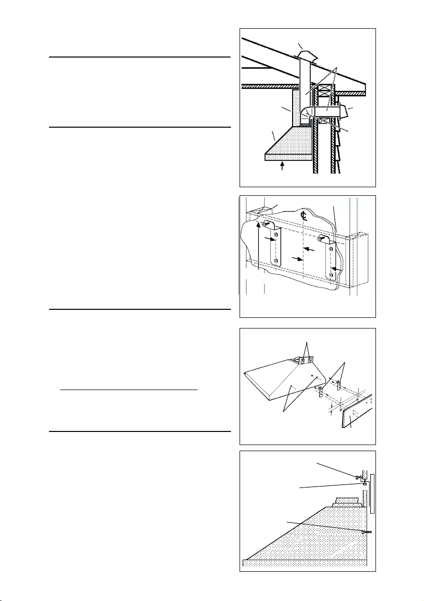
INSTALL THE DUCTWORK
NOTE: To reduce the risk of fire, use only
metal ductwork.
1. Decide where the ductwork will run between
the hood and the outside.
2. A straight, short duct run will allow the hood
to perform most efficiently.
3. Long duct runs, elbows, and transitions will
reduce the performance of the hood. Use as
few of them as possible.
4. Install a roof or wall cap. Connect 6" round
metal ductwork (8” for K42) to cap and work
back towards hood location. Use duct tape
to seal the joints between ductwork sections.
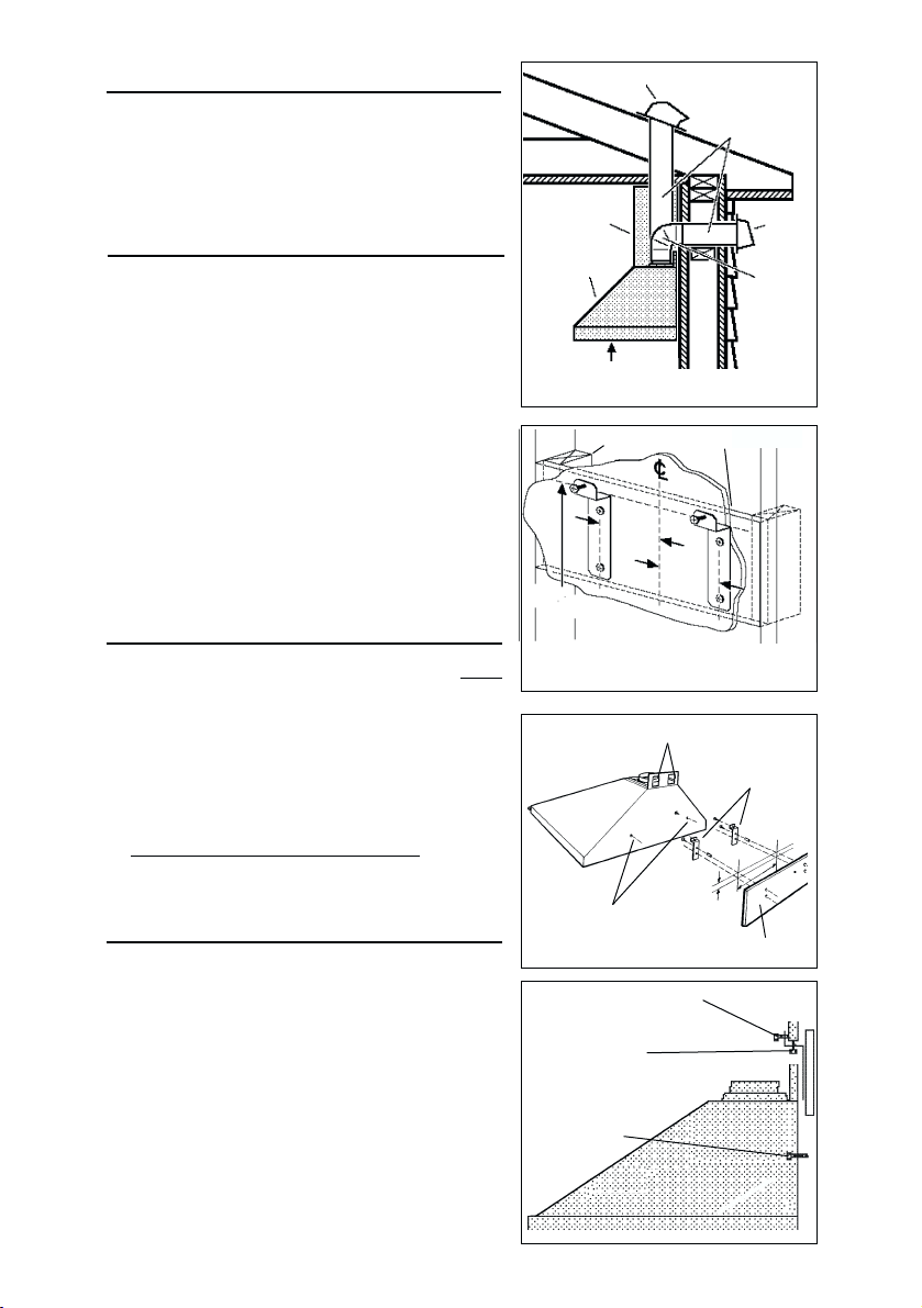
INSTALL MOUNTING
BRACKETS
1. Construct wood wall framing that is flush
with interior surface of wall studs.
Make sure:
a) the framing is centered over installation
location.
b) the height of the framing will allow the
mounting brackets to be secured to the
framing within the dimensions shown.
After wall surface is finished, secure
2.
mounting brackets to framing using
dimensions shown.
INSTALL THE HOOD
3. Hang the hood from the brackets through
the rectangular cut-outs on the back of the
hood. Cut-outs are larger than the brackets
to allow for horizontal adjustment.
The bottom of the hood should be 24" to 30"
above the cooking surface.
4. Height adjustment screws provide vertical
adjustment.
5. Depth adjustment screws provide
horizontal adjustment.
6. Secure the hood with additional mounting
screws. Use drywall anchors, provided, if
wall studs or framing are not available.
- 3 -
ROOF CAP
DECORATIVE
FLUE
HOOD
24” TO 30” ABOVE
COOKING SURFACE
FRAMING BEHIND DRYWALL
3-3/4
3
38
/
to 44
1
6
3
/
above cooktop
1
6
383/16"= bottom of hood 24" above cooktop
3
/16"= bottom of hood 30" above cooktop
44
RECTANGULAR CUTOUTS
ADDITIONAL
MOUNTING
SCREWS
DEPTH ADJUSTMENT
SCREWS
HEIGHT
ADJUSTMENT
SCREWS
ADDITIONAL
MOUNTING
SCREWS
6” ROUND
DUCT
(8” for K42)
WALL
CAP
6” ROUND
ELBOW
(8” for
K42)
3-3/4
MOUNTING
BRACKETS
WALL FRAMING
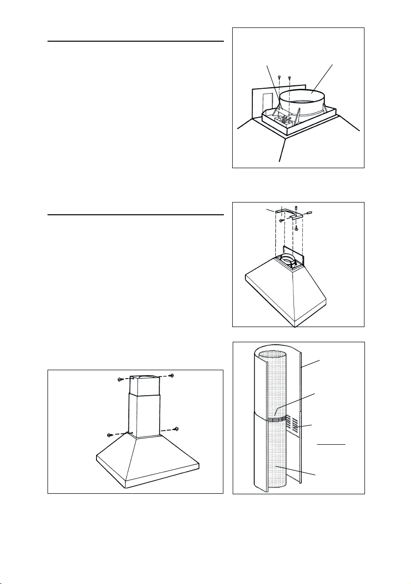
WIRING
Note: This range hood must be properly
grounded. The unit should be installed by a
qualified electrician in accordance with all
applicable national and local electrical codes.
1. Remove the wiring box cover. Remove a
knockout from the wiring box.
2. Feed 6" of power cable through the knockout
opening and secure cable to the wiring box
with an appropriate connector.
3. Make electrical connections. Connect white
to white, black to black and green to green.
4. Replace wiring box cover and screws. Make
sure that wires are not pinched between
cover and box.
WIRING BOX
COVER
DUCT
COLLAR
CONNECT DUCTWORK
Ducted Configuration
1. Use screws and wall anchors to secure
upper bracket to the ceiling and wall as
shown.
2. Use 6" round metal duct (8” for K42) to
connect the duct collar on the hood to the
ductwork above.
3. Use duct tape to make all joints secure and
air tight.
4. Connect the upper section of decorative flue
to the bracket with screws provided.
5. Slide the lower section of decorative flue
downward, until it fits properly around hood.
6. Secure decorative flue to hood with screws
provided.
FASTEN
FLUE TO
HOOD & UPPER
BRACKET WITH
SCREWS
UPPER
BRACKET
FASTEN
UPPER
BRACKET
TO CEILING &
WALL WITH
SCREWS (&
ANCHORS IF
NECESSARY)
DECORATIVE
FLUE
DUCT TAPE
AIR VENT
POSITION FOR
DUCTED
CONFIGURATION
6" ROUND
METAL DUCT
(8” for K42)
- 4 -
CONNECT DUCTWORK
Ductfree Configuration
1. Use screws and wall anchors
UPPER
FLUE SECTION
AIR
VENTS
(in upper flue section)
UPPER
BRACKET
(supplied) to secure the upper
bracket to wall and ceiling as
shown.
2. Turn upper flue section upside down
so air vents are at the top. Slide
upper flue section into lower flue
section.
3. Snap the plastic duct collar into the
hole in the bottom of the ducfree
plenum. Connect the ductfree
plenum to the upper flue section with
(4) flat-head screws (supplied).
DUCTFREE
PLENUM
PLASTIC
DUCT COLLAR
LOWER
FLUE SECTION
6" ROUND
METAL DUCT
(8” for K42)
DISCHARGE
COLLAR
MEASURE
DUCT
SEAM
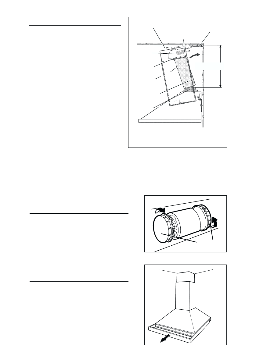
4. Measure the distance from the top
of the discharge collar to the ceiling.
Cut a length of 6" round metal duct
(8” for K42) 6" shorter than this
dimension.
5. Fit duct section over the plastic duct
collar. For best fit, make sure duct seam is toward the front.
6. Set duct/flue assembly on hood with top tilted away from wall. Reach around flue
to engage bottom of duct with discharge collar on hood. Tilt flue up against wall.
Duct seam can be cut to length if necessary.
7. Raise upper flue section and screw it to upper bracket with (2) screws (supplied).
Screw lower flue section to hood with screws (supplied).
DUCTFREE FILTER
INSTALLATION
1. Purchase a ductfree filter kit (ROUND
FILTER) from your dealer.
2. Position the filters over the mounting
brackets on the blower inlet.
3. Rotate to lock filters in place.
BOTTOM TRIM
REPLACEMENT
1. Remove trim by pulling it frontwards.
2. Slide new trim inward onto hood.
DUCTFREE
FILTERS
- 5 -
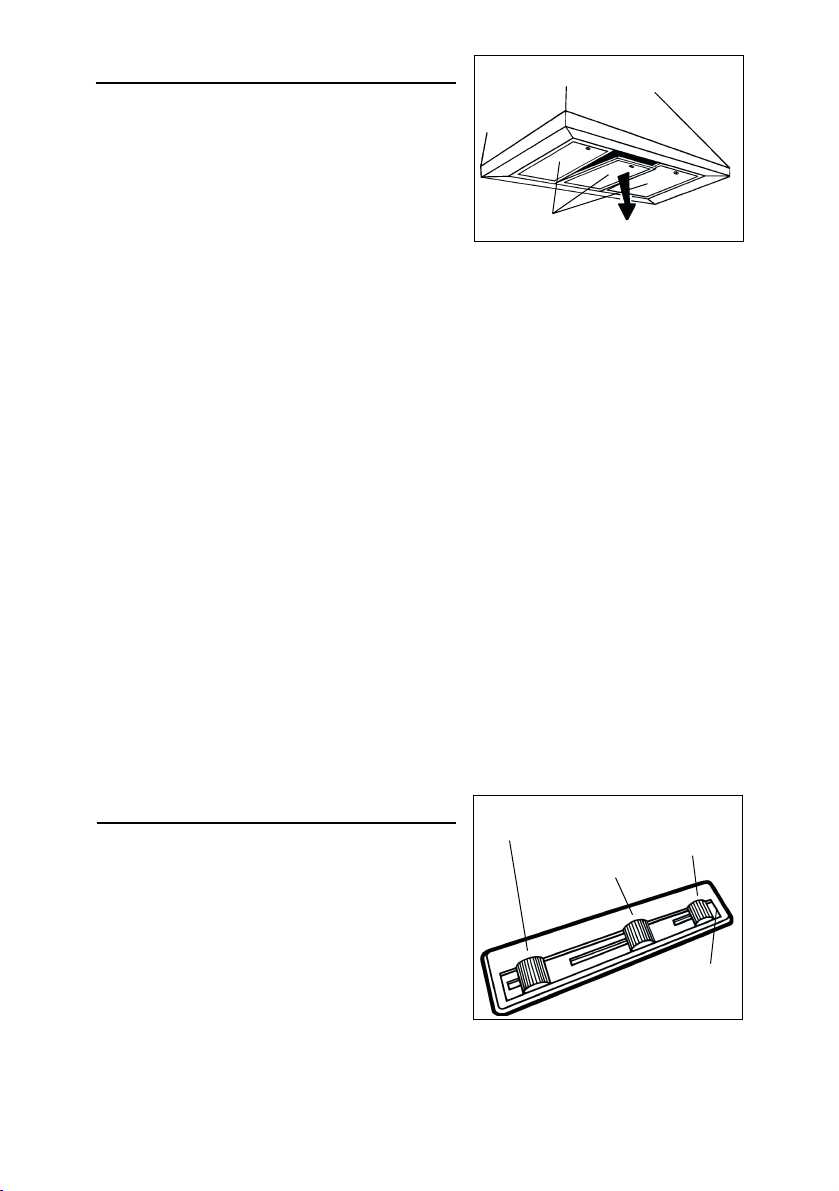
MAINTENANCE
Grease Filters
The grease filters should be cleaned frequently.
Use a warm detergent solution. Grease filters
are dishwasher safe.
Remove filters by pushing filters towards the
back of hood and rotating filters downward.
Ductfree Filters
The ductfree filters should be changed every 6 months. Rotate the filters to remove
and replace.
Hood Cleaning
Stainless steel is one of the easiest materials to keep clean. Occasional care will
help preserve its fine appearance.
Cleaning tips:
l Hot water with soap or detergent is all that is usually needed.
l Follow all cleaning by rinsing with clear water. Wipe dry with a clean, soft cloth to
avoid water marks.
l For discolorations or deposits that persist, use a non-scratching household cleanser
or stainless steel polishing powder with a little water and a soft cloth.
l For stubborn cases, use a plastic scouring pad or soft bristle brush together with
cleaser and water. Rub lightly in direction of polishing lines or "grain" of the stainless
finish. Avoid using too much pressure which may mar the surface.
l DO NOT allow deposits to remain for long periods of time.
l DO NOT use ordinary steel wool or steel brushes. Small bits of steel may adhere
to the surface causing rust.
l DO NOT allow salt solutions, disinfectants, bleaches, or cleaning compounds to
remain in contact with stainless steel for extended periods. Many of these
compounds contain chemicals which may be harmful. Rinse with water after
exposure and wipe dry with a clean cloth.
Painted surfaces should be cleaned with warm water and mild detergent only.
GREASE FILTERS
OPERATION
Controls
The hood is operated using the slide controls
under the front edge of the hood.
The light switch turns the halogen lights on
and off.
The blower on / off switch turns the blower on
to the running speed set by the blower speed
control. The blower must be turned on and off
using this switch.
The blower speed control changes the running speed of the blower. It is infinitely adjustable
from low to high speed.
The pilot lamp lights up whenever the blower
is on.
- 6 -
LIGHT
SWITCH
BLOWER
SPEED
CONTROL
BLOWER
ON / OFF
SWITCH
PILOT
LAMP
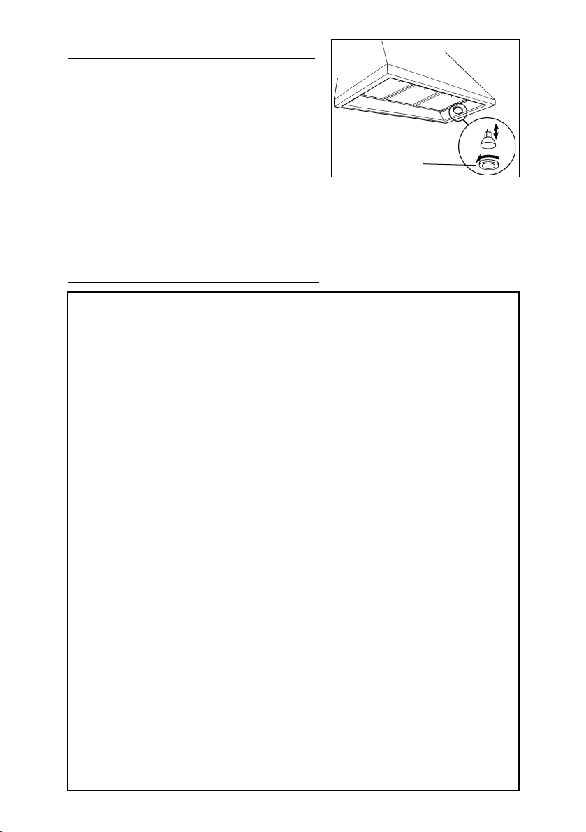
HALOGEN BULBS
This range hood requires two halogen bulbs
(Type 12V, 20W).
ALWAYS SWITCH OFF THE ELECTRICITY
SUPPLY BEFORE CARRYING OUT ANY
OPERATIONS ON THE APPLIANCE.
To change bulbs:
1. Slacken the ring nut in an anticlockwise
direction.
2. Remove the bulb by pulling sideward (Do not rotate). CAUTION: BULB MAY BE
HOT!
3. Replace with a bulb of the same type.
BULB
RING NUT
WARRANTY
BROAN ONE YEAR LIMITED WARRANTY
Broan warrants to the original consumer purchaser of its products that such
products will be free from defects in materials or workmanship for a period of
one year from the date of original purchase. THERE ARE NO OTHER WARRANTIES, EXPRESS OR IMPLIED, INCLUDING, BUT NOT LIMITED TO,
IMPLIED WARRANTIES OR MERCHANT ABILITY OR FITNESS FOR A PARTICULAR PURPOSE.
During this one-year period, Broan will, at its option, repair or replace, without
charge, any product or part which is found to be defective under normal use
and service. THIS WARRANTY DOES NOT EXTEND TO FLUORESCENT
LAMP STARTERS, TUBES. This warranty does not cover (a) normal maintenance and service or (b) any products or parts which have been subject to
misuse, negligence, accident, improper maintenance or repair (other than by
Broan), faulty installation or installation contrary to recommended installation instructions.
The duration of any implied warranty is limited to the one-year period as
specified for the express warranty. Some states do not allow limitation on
how long an implied warranty lasts, so the above limitation may not apply to
you.
BROAN’S OBLIGATION TO REPAIR OR REPLACE, AT BROAN’S OPTION,
SHALL BE THE PURCHASER’S SOLE AND EXCLUSIVE REMEDY UNDER
THIS WARRANTY. BROAN SHALL NOT BE LIABLE FOR INCIDENTAL,
CONSEQUENTIAL OR SPECIAL DAMAGES ARISING OUT OF OR IN CONNECTION WITH PRODUCT USE OR PERFORMANCE. Some states do not
allow the exclusion or limitation of incidental or consequential damages, so
the above limitation or exclusion may not apply to you.
This warranty gives you specific legal rights, and you may also have other
rights, which vary from state to state. This warranty supersedes all prior
warranties.
To qualify for warranty service, you must (a) notify Broan at the address
stated below or telephone: 1-800-637-1453, (b) give the model number and
part identification and (c) describe the nature of any defect in the product or
part. At the time of requesting warranty service, you must present evidence of
the original purchase date.
BEST BY BROAN, P.O. Box 140 Hartford, Wisconsin 53027
- 7 -

LISEZ ET CONSERVEZ CES INSTRUCTIONS
AVERTISSEMENTS
PEUT ÊTRE UTILISÉ DANS LES ZONES CUISSON DES
CUISINES FAMILIALES.
POUR REDUIRE LES RISQUES D’INCENDIE, DE
DECHARGES ELECTRIQUES OU DE DOMMA-GES AUX
PERSONNES, OBSERVEZ LES IN-STRUCTIONS
SUIVANTES:
1. N’utilisez cet appareil que comme cela est indiqué par le
constructeur. Si vous avez des problèmes, contactez le
fabriquant à l’adresse ou au numéro de téléphone
indiqués dans la garantie.
2. Avant de pourvoir à l’entretien ou au nettoyage de votre
appareil, éteignez-le au tableau des commandes ou
bloquez le tableau des commandes afin d’éviter de le
mettre en marche accidentellement. Si vous ne pouvez
pas bloquer le système permettant d’éteindre votre
appareil, appliquez un avertissement extérieur d’une
façon sure, comme par exemple un panneau, sur le
tableau des commandes.
3. L’assemblage et la connexion électrique doivent être faits
par des personnes qualifiées en respectant les normes
et règlements en vigueur, y compris les normes et
règlements concernant les possibilités d’incendie.
4. Il est indispensable qu’il y ait suffisamment d’air pour que
la combustion et l’évacuation des gaz à travers le tuyau
du brûleur du combustible ait lieu sans retour de flamme.
Suivez les indications données par le fabricant du brûleur
ainsi que les normes de sécurité comme celles qui sont
publiées par l’Association Nationale pour la Protection
contre les Incendies National Fire Protection Association
(NFPA) et la American Society for Heating, Refrigeration
and Air Conditioning Engineers (ASHRAE), et les autorités
locales en matière de normes.
5. Quand vous coupez ou percez des trous dans le mur ou
le plafond, n’abîmez pas les fils électriques ou autres.
6. Le ventilateur canalisé doit toujours évacuer l’air vers
l’extérieur.
7. N’utilisez pas cet appareil avec un appareil contrôlant la
vitesse à état solide.
8. Afin de diminuer tout risque d’incendie n’utilisez que des
conduits en métal.
9. Votre appareil doit être relié à la terre.
ATTENTION - POUR REDUIRE LES RISQUES
D’INCENDIE DES MATIERES GRASSES QUI SONT EN
TRAIN DE CUIRE:
A. Ne laissez jamais ni vos éléments chauffants, ni vos
casseroles ou poêles sur le feu sans les contrôler si
vous réglez l’apport de chaleur sur une position élevée.
Si vos casseroles ou poêles débordent cela provoque
de la vapeur et des éclaboussures de graisse qui peuvent
prendre feu. Chauffez les huiles lentement à feu bas ou
moyen.
B. Faites toujours fonctionner votre hotte quand vous cuisez
à des températures élevées ou quand vous cuisinez
des plats flambés.
C. Nettoyez régulièrement les ailes de vos ventilateurs.
Ne permettez pas que la graisse s’accumule sur le
ventilateur ou sur le filtre.
D. Utilisez des casseroles de taille appropriée. Utilisez
toujours des ustensiles de cuisson dont la taille est
appropriée à la surface de votre élément de cuisson.
AVERTISSEMENTS
POUR REDUIRE LES RISQUES DE DOMMAGES AUX
PERSONNES AU CAS OÙ VOTRE CUISI-NIERE
PRENDRAIT FEU, OBSERVEZ LES INSTRUCTIONS
SUIVANTES:*
1. ETEINDRE LES FLAMMES à l’aide d’un couvercle le
2. NE PRENEZ JAMAIS EN MAIN UNE POÊLE OU UNE
3. N’UTILISEZ PAS D’EAU, ni torchons ou serviettes
4. Utilisez un extincteur SEULEMENT si:
ATTENTION
1. Pour réduire tout risque d’incendie et pour évacuer
2. Faites très attention quand vous utilisez des produits
3. Évitez d’utiliser des aliments pouvant s’enflammer sous
4. N’utilisez cet appareil que pour une ventilation générale.
5. Pour éviter de causer des dommages au moteur et de
6. Le moteur de votre hotte a un thermostat qui éteindra
7. Pour mieux capturer les impuretés de cuisine, le bas de
8. Vu que cette hotte est grande et lourde, il est
9. Nous vous recommandons de lire l’étiquette indiquant
- 8 -
plus hermétique possible, une plaque à gâteaux, ou un
plateau en métal, puis éteindre le brûleur. ATTENTION
à NE PAS VOUS BRÛLER. Si les flammes ne s’éteignent
pas immédiatement, SORTEZ ET APPELEZ LES
POMPIERS.
CASSEROLE QUI A PRIS FEU - Vous pourriez vous
brûler.
mouillés - vous provoqueriez une violente explosion de
vapeur.
A. Vous savez que vous avez un extincteur Classe
ABC, et vous en connaissez déjà le mode d’emploi.
B. Ce n’est pas un très gros incendie et qu’il se limite
à l’endroi où il a explosé.
C. Vous êtes en train d’avertir les pompiers.
D. Vous avez la possibilité d’essayer d’éteindre l’incendie
en ayant le dos tourné vers une issue.
* D’après les “Suggestions concernant la Sécurité contre
les incendies des cuisines” publiées par NFPA.
correctement l’air, assurez-vous de prévoir un conduit
de ventilation extérieur. Ne videz pas l’air dans les
espaces limités par des murs ou des plafonds, les
combles, les passages étroits ou les garages.
de nettoyage ou des détergents.
la Range Hood.
Ne l’utilisez pas pour évacuer des matières ou des
vapeurs dangereuses ou qui peuvent exploser.
rendre les rotors bruyants et/ou non équilibrés, évitez
que les sprays pour murs secs, la poussière de
construction entrent en contact avec la partie électrique.
automatiquement le moteur s’il est surchauffé. Le moteur
se remettra en marche lorsqu’il se sera refroidi. Si le
moteur continue à s’éteindre et à se remettre en marche,
faites vérifier votre hotte.
votre hotte devrait être à une distance minimum de 24”
et à une distance maximum de 30” au-dessus du plan
de cuisson.
recommandé de confier l’installation de cette hotte à
deux personnes.
les caractéristiques de votre hotte pour de plus amples
informations et exigences.
INSTALLATION DU PANNEAU
POSTERIEUR (OPTIONNEL)
Si vous avez choisi d’utiliser le panneau postérieur,
accrochez-le au mur. Fixez les étriers d’assemblage
au panneau mais n’assemblez pas le cadre allant
contre le mur qui est décrit plus bas.
INSTALLATION DU SYSTEME
D’EVACUATION
REMARQUE: Pour réduire les risques
d’incendie, n’utilisez que des tuyaux en métal.
1. Décidez où le tuyau doit être installé, entre
votre hotte et l’extérieur.
2. Un tuyau droit et court permettra à votre hotte
de fonctionner d’une façon plus efficace. Un
tuyau long avec des coudes et des transitions
réduira le bon fonctionnement de votre hotte.
En utiliser le moins possible.
3. Installez un couvercle sur le toit ou au mur.
Reliez un tuyau en métal rond de 6” (8” pour
K42) au couvercle et faites-le aller jusqu’à
l’emplacement de votre hotte. Rendez les
jonctions du tuyau hermétiques au moyen d’un
ruban pour tuyaux.
INSTALLATION DES ETRIERS
D’ASSEMBLAGE
1. Construisez un cadre en bois pour le mur dont
les vis-pivot ne dépassent pas. Assurez-vous:
a) que le cadre est centré au-dessus de
l’emplacement de l’installation.
b) la hauteur du cadre permettra que les
étriers d’assemblage soient fixés au cadre
en respectant les dimensions indiquées.
2. Après avoir terminé la surface du mur, fixez les
étriers d’assemblage au cadre en respectant
les dimensions qui sont indiquées.
INSTALLATION DE VOTRE HOTTE
1. Accrochez votre hotte aux étriers par les trous
rectangulaires qui se trouvent derrière votre
hotte. Les trous sont plus grands que les étriers
afin de vous permettre d’ajuster le tout
horizontalement. Le fond de votre hotte devrait
être à entre 24” et 30” au-dessus de la surface
de cuisson.
2. Les vis de réglage en hauteur permettent de
régler verticalement. Les vis de réglage en
profondeur permettent de régler
horizontalement.
3. Fixez votre hotte avec des vis d’assemblage
de securité. Utilisez des chevilles pour mur à
sec, qui vous sont fournies, si vous ne trouvez
pas les vis-pivot ou le cadre.
- 9 -
COUVERCLE DU TOIT
TUYAU ROND
DE 6”
(8” pour K42)
CONDUIT
DÉCORATIF
HOTTE
DE 24” À 30” AU-DESSUS
DU PLAN DE CUISSON
CADRE POUR LE MUR
3-3/4
3-3/4
de 38
3
/
à 44
1
du plan de cuisson
6
3
/
au-dessus
1
6
383/16"= si la distance entre la hotte et le plan de cuisson cest de 24
443/16"= si la distance entre la hotte et le plan de cuisson cest de 30
TROUS RECTANGULAIRES
VIS D’ASSEMBLAGE
DE SECURITE
VIS DE REGLAGE EN
PROFONDEUR
VIS DE
REGLAGE EN
HAUTEUR
VIS D’ASSEMBLAGE
DE SECURITE
PLANCHE DE BOIS
POUR L'ADAPTATION
COUVERCLE
COUDE ROND
DE 6”
(8” pour K42)
ETRIERS
DU
MUR
 Loading...