

Page 1
MODEL BCR1
RANGE HOOD
REMOTE CONTROL
READ AND SAVE THESE
INSTRUCTIONS
Your Broan BCR1 remote control is a Radio Frequency
(RF) wireless device used to op erate the fan, lights, and
delay-off feature on compatible Broan range hoods.
Refer to your hood installation manual or product
specification sheet to ensure your hood is compatible
with Broan model BCR1 remote control.
Unlike Infrared (IR) remotes, which are the most
common, RF remotes are easier to use because
they do not require line of sight, so they do not
have to be aimed directly at the equipment they are
controlling. RF is a very convenient, reliable method
to transmit commands without wires for the operation
of your compatible range hood. This system will offer
exceptional performance in most cases. Although
signals will often travel great distances, as well as
around and through structures/walls, there are some
limitations to the operating range. See troubleshooting
guide on page1 regarding these limitations.
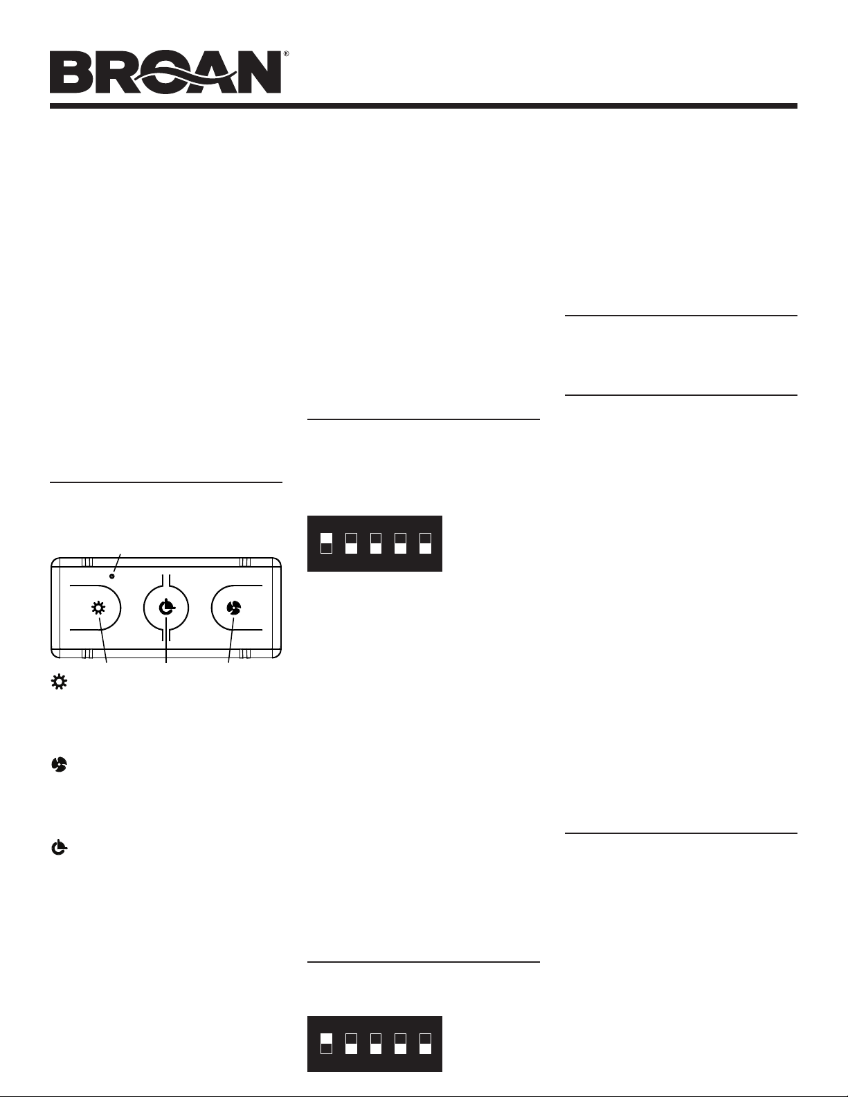
CONTROL OPERATION
When a button is depressed on the remote control,
it sends a coded signal to the receiver installed
on a Broan compatible hood, telling it which
function to activate.
LED INDICATOR
FANDELAY-OFFLIGHT
Light Button – When the hood lights are OFF,
pressing the light button will turn the hood lights ON
to the lowest setting. Pressing again will index the
lights to the next highest setting. When lights are at
the highest setting, pressing the button again will turn
lights OFF.
Fan Button – When the hood fan is OFF,
pressing the fan button will turn the hood fan ON
to the lowest setting. Pressing again will index the
fan speed to the next highest setting. When hood fan
is at its highest setting, pressing the button again will
turn fan OFF.
Delay off Button – When hood fan is ON, pressing
the Delay-OFF button will activate the Delay-OFF
feature of the hood. Pressing again will turn the DELAYOFF feature OFF. If the hood fan is OFF, pressing the
button will have no effect.
The green LED indicator on the remote will
illuminate to indicate that the function has been
transmitted. An audible “beep” at the hood, and change
in function will indicate that the hood has received the
transmission.
Your Broan remote control comes equipped with
magnetic, non-slip feet. It can be adhered to a vertical
metal/magnetic surface (such as a refrigerator door) or
placed on a horizontal surface.
The RF encoder on your remote control is a fixed
address encoder, meaning the address (security)
code can be changed to another code manually.
There exists a slight possibility of interference from
other RF remote controls (garage door transmitter,
home and car security systems, remote control
paddle fans, other range hoods installed nearby).
To resolve interference issues, the address or code
can be changed (up to 32 independent address
codes) by changing the settings on the 5 position
DIP switches on the handheld remote. Note that in
most cases, this will not be necessary. The product
is shipped from the factory (transmitter and receiver)
with DIP address settings set to matching codes
(switch 1 set to ON - switches 2-5 set to OFF). Assuming
there are no interference issues, the user won’t need to
change the DIP switch address code settings.
For some hood models, a specific linking procedure
between the hood and remote control is required
before use. Refer to your hood installation instructions
for further information.
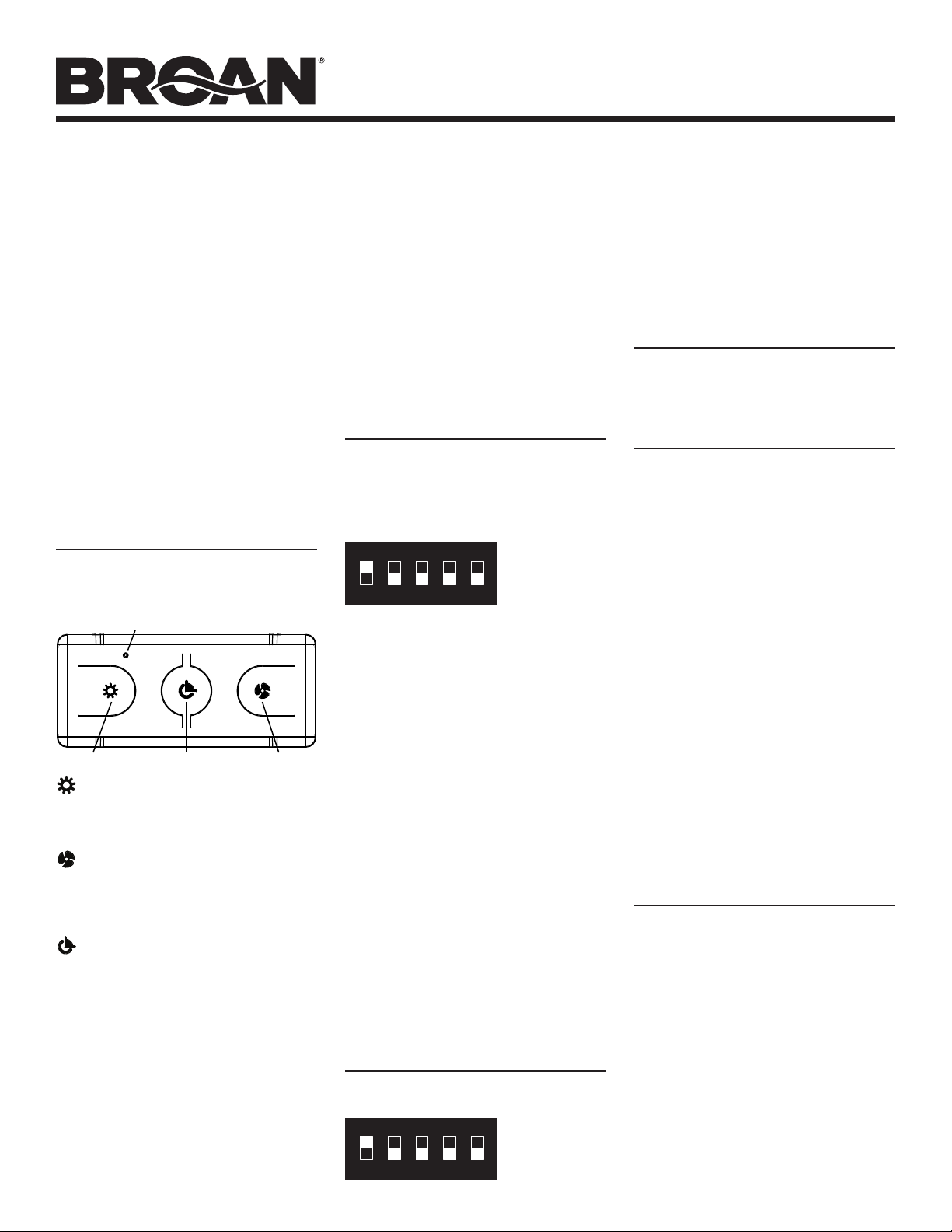
CHANGING SECURITY CODES
Remote (Transmitter)
Open the back cover of the remote by removing the
center screw, and placing a flat screwdriver in between
two halves of the housing to pry apart.
Locate the 5-position DIP switch on the circuit board.
ON
1 2 3 4 5
Using a small insulated screwdriver or other nonconductive instrument, adjust one or more of the
5 DIP switches to a different position (ON or OFF).
Note that SWITCH “1” was factory-set to the “ON”
position and SWITCHES “2-5” were factory-set to the
“OFF” position. Prior to re-assembling the remote,
carefully note the new DIP switch settings so the same
settings can be used on the hood (receiver). Carefully
reassemble the remote.
SWITCH “1”
SHOWN “ON”
SWITCHES “2-5”
SHOWN “OFF”
Hood (Receiver)
WARNING – TO REDUCE THE RISK OF FIRE,
ELECTRIC SHOCK, OR INJURY TO PERSONS,
OBSERVE THE FOLLOWING: IF YOU HAVE
QUESTIONS, CONTACT THE MANUFACTURER AT
THE ADDRESS OR TELEPHONE NUMBER LISTED
IN THE WARRANTY. BEFORE SERVICING OR
CLEANING UNIT, SWITCH POWER OFF AT SERVICE
PANEL AND LOCK THE SERVICE DISCONNECTING
MEANS TO PREVENT POWER FROM BEING
SWITCHED ON ACCIDENTALLY.WHEN THE
SERVICE DISCONNECTING MEANS CANNOT BE
LOCKED, SECURELY FASTEN A PROMINENT
WARNING DEVICE, SUCH AS A TAG, TO THE
SERVICE PANEL. ELECTRICAL WORK MUST
BE DONE BY A QUALIFIED PERSON(S) IN
ACCORDANCE WITH ALL APPLICABLE CODES
AND STANDARDS.
FOR BROAN QP3 & QP4 SERIES HOODS
Locate the 5-position DIP switch on the hood
(usually located on the circuit board) – refer to your
hood installation instruction for additional details
if necessary.
ON
1 2 3 4 5
SWITCH “1”
SHOWN “ON”
SWITCHES “2-5”
SHOWN “OFF”
Page 1
Using a small insulated screwdriver or other nonconductive instrument, adjust the DIP switches to the
same settings as the remote control. Reassemble any
parts from hood that were removed to access the DIP
switches.
Verify the function of the remote control and hood
once DIP switch settings are properly paired. New
settings may be needed if interference issues are still
encountered.
FOR BROAN ELITE EW56, EW58 &
EI59 SERIES HOODS
After changing DIP switch settings on the hand-held
remote, refer to your hood installation instructions for
additional details regarding linking to the remote.
CLEANING AND MAINTENANCE
Clean surfaces with a damp, clean cloth and mild
detergent only.
Do not immerse in water. Your remote is
considered to be “splash-proof”, not “waterproof”.
Your Broan remote transmitter is a user friendly device
designed for years of trouble free operation. Under
most circumstances it should require only periodic
battery replacement. The transmitter is powered by
a long life A23-style 12V battery available at most
hardware stores or home centers. The battery on your
remote control should last in excess of 1-year under
normal operation.
To change the battery, remove the battery cover by
us ing a sma l l flat blad e d screwdr i ver to ge ntly pry open.
Remove existing battery utilizing a small insulated
flat bladed screwdriver or other non-conductive
instrument, and discard properly with consideration to
local codes and recycling guidelines. Install the new
battery while ensuring the “+” side of the battery lines
up with the “+” terminal of the remote. Replace cover.
WARNING – TO PREVENT POSSIBLE SERIOUS
INJURY OR DEATH: NEVER ALLOW SMALL
CHILDREN NEAR BATTERIES. IF BATTERY IS
SWALLOWED, IMMEDIATELY NOTIFY DOCTOR
Notice: Operation is subject to the following two
conditions: (1) This device may not cause interference,
and (2) this device must accept any interference that
may cause undesired operation of the device.
TROUBLE SHOOTING GUIDE
Remote transmitting signal (green LED illuminates)
but hood not receiving
• Ensure hood is powered.
• Battery weak – install new fresh A23-12V battery
• Check the receiver (if applicable) and transmitter
DIP switches are set at the same setting.
• Perform linking procedure between hood and
remote (some models).
Transmission Range Short
• Change orientation of remote when activating
• Change location of remote to minimize obstructions
• Battery weak – install new fresh A23-12V battery
Interference encountered with other RF transmitters
or receivers
• Change encoder DIP switch settings. (Re-link if
necessary - depending on hood model.)
Page 2
MODÈLE BCR1
TÉLÉCOMMANDE
DEHOTTE DE CUISINE
LIRE CES DIRECTIVES
ETLES CONSERVER
Votre télécommande Broan BCR1 est un dispositif sans fil à
radiofréquence (RF) commandant le ventilateur, l’éclairage
et la fonction d’arrêt différé des hottes Broan compatibles.
Consultez le manuel d’installation de votre hotte ou la feuille de
spécifications du produit pour vous assurer que votre hot te est
compatible avec la télécommande Broan BCR1.
Contrairement aux télécommandes à infrarouges (IR), qui
sont les plus courantes, les télécommandes RF sont plus
faciles à utiliser parce qu’elles n’exigent pas de ligne de
visée ni d’être pointées directement vers l’appareil qu’elles
commandent. Les radiofréquences sont un moyen très
pratique et fiable d’émettre des commandes, sans aucun
fil, pour faire fonctionner une hotte de cuisine compatible.
Ce système offrira un rendement exceptionnel dans la plupart
des cas. Bien que les signaux peuvent parcourir souvent
de grandes distances, même au travers des murs et des
structures, il y a toutefois des limites à leur por tée. Consultez le
guide de dépannage à la page 2 au sujet de ces limites.
FONCTIONNEMENT DE
LA COMMANDE
Lorsque vous appuyez sur un bouton de la télécommande,
celle-ci envoie un signal codé au récepteur installé sur
la hotte Broan compatible, commandant ainsi l’activation d’une
fonction.
INDICATEUR DEL
ÉCLAIRAGE
Bouton éclairage – Lorsque l’éclairage de la hotte est
ÉTEINT, ce bouton ALLUME l’éclairage à l’intensité la plus
faible. Si vous appuyez de nouveau, les lumières passent
à l’intensité suivante. Lorsque l’éclairage est à la plus forte
intensité, appuyez sur ce bouton pour éteindre l’éclairage.
Bouton ventilateur – Lorsque le ventilateur de la hotte
est ARRÊTÉ, ce bouton ACTIONNE le ventilateur à l’intensité
la plus faible. Si vous appuyez de nouveau, le ventilateur
passe à l’intensité suivante. Lorsque le ventilateur est au
régime maximal, appuyez sur ce bouton pour ARRÊTER
le ventilateur.
Bouton arrêt différé – Lorsque le ventilateur est en
MAR CHE, ce bouto n activ e la fon c tion d’ar rêt dif féré de la hot te.
Si vous appuyez de nouveau, la fonction est DÉSACTIVÉE.
Lorsque la hotte est ARRÊTÉE, ce bouton n’a aucun effet.
L’indicateur DEL vert de la télécommande s’allumera pour
indiquer que le signal de la fonction est émis. La hotte produira
un léger « bip » sonore pour confirmer la réception du signal.
Votre télécommande Broan est munie de pieds magnétiques
antidérapants. Elle adhèrera à toute surface magnétique ou
métallique verticale (comme la porte d’un réfrigérateur) et peut
aussi être placée sur une surface horizontale.
L’encodeur RF de la télécommande est un encodeur à
adresse fixe, ce qui signifie que le code d’adresse
(de sécurité) ne peut être changé que manuellement. Il y a
une faible possibilité d’interférence venant d’autres
télécommandes RF (émetteur d’un ouvre-porte de garage,
ARRÊT DIFFÉRÉ
VENTILATEUR
systè mes d’a larme de la ma ison ou de l’auto mobi le, ve ntilateu rs
sur pied avec télécommande, autres hottes de cuisine
installées dans les environs). Pour résoudre les problèmes
d’interférence, vous pouvez changer le code d’adresse
(jusqu’à 32 codes d’adresse distincts) en changeant la
position des cinq commutateurs DIP sur la manette de la
télécommande. Veuillez noter que, dans le plupart des cas,
cela n’est pas nécessaire. Le produit est expédié de l’usine
(émetteur et récepteur) avec des réglages d’adresses DIP
à codes correspondants (commutateur « 1 » réglés sur
MARCHE - commutateurs « 2 À 5 » réglés sont ARRÊT).
En supposant qu’il n’y a pas de problème d’interférences,
l’utilisateur n’a pas à modifier les codes d’adresse à l’aide
des commutateurs DIP.
Pour certains modèles de hotte, il est nécessaire d’utiliser une
procédure de liaison particulière entre la hotte et la télécommande avant l’utilisation. Pour de plus amples informations,
consultez les directives d’installation de votre hotte.
À l’aide d’un petit tournevis isolé ou d’un autre instrument
non conducteur, réglez les commutateurs DIP de la même
façon que ceux de la télécommande. Remontez les pièces
de la hotte que vous avez enlevées pour accéder aux
commutateurs DIP.
Vérifiez le fonctionnement de la télécommande et de
la hotte, une fois les commutateurs DIP correctement
réglés. De nouveaux réglages peuvent s’avérer
nécessaires si des interférences posent encore
un problème.
POUR LES HOTTES BROAN ELITE
SÉRIES EW56, EW58 ET EI59
Après avoir modifié la position des commutateurs DIP
sur la télécommande à main, consultez les directives
d’installation de votre hotte pour plus de détails
CHANGEMENT DES CODES
DE SÉCURITÉ
Télécommande (émetteur)
Ouvrez le couvercle arrière en enlevant la vis centrale et placez
un tournevis plat entre les deux moitiés du boîtier pour les
séparer.
Localisez les cinq commutateurs DIP sur le circuit imprimé.
ON
1 2 3 4 5
À l’aide d’un petit tournevis isolé ou d’un autre instrument
non conducteur, placez un ou plusieurs des cinq
commutateurs DIP dans une position différente (MARCHE
ou ARRÊT). Remarquez que le COMMUTATEUR « 1 » a été
placé sur MARCHE à l’usine et que les COMMUTATEURS
« 2 À 5 » sont préréglés sur ARRÊT. Avant de remonter
la télécommande, notez soigneusement la position des
commutateurs DIP afin de les régler de la même façon
sur la hotte (le récepteur). Remontez soigneusement
la télécommande.
COMMUTATEUR « 1 »
SUR MARCHE
COMMUTATEURS « 2 À 5 »
SUR ARRÊT
Hotte (récepteur)
AVERTISSEMENT – OBSERVEZ LES DIRECTIVES
CI-DESSOUS AFIN DE RÉDUIRE LES RISQUES
D’INCENDIE, DE CHOC ÉLECTRIQUE OU DE BLESSURES
CORPORELLES : SI VOUS AVEZ DES QUESTIONS,
COMMUNIQUEZ AVEC LE FABRICANT À L’ADRESSE
OU AU NUMÉRO DE TÉLÉPHONE INDIQUÉS DANS LA
GARANTIE. AVANT DE PROCÉDER À L’ENTRETIEN
OU AU NETTOYAGE DE L’APPAREIL, COUPEZ
L’ALIMENTATION DU PANNEAU ÉLECTRIQUE ET
VERROUILLEZ L’INTERRUPTEUR PRINCIPAL AFIN
D’EMPÊCHER QUE LE COURANT NE SOIT
ACCIDENTELLEMENT RÉTABLI. S’IL EST IMPOSSIBLE
DE VERROUILLER L’INTERRUPTEUR PRINCIPAL,
FIXEZ SOLIDEMENT UN MESSAGE D’AVERTISSEMENT,
PAR EXEMPLE UNE ÉTIQUETTE, SUR LE PANNEAU
ÉLECTRIQUE. LES TRAVAUX D’ÉLECTRICITÉ DOIVENT
ÊTRE EFFECTUÉS PAR DES PERSONNES QUALIFIÉES
CONFORMÉMENT AUX CODES ET AUX NORMES
ENVIGUEUR.
POUR LES HOTTES BROAN SÉRIES QP3 ET QP4
Localisez les cinq commutateurs DIP de la hot te (habituellement
sur le circuit imprimé) – si nécessaire, consultez les directives
d’installation pour des renseignements plus détaillés.
ON
1 2 3 4 5
COMMUTATEUR « 1 »
SUR MARCHE
COMMUTATEURS « 2 À 5 »
SUR ARRÊT
concernant la liaison de la télécommande.
NETTOYAGE ET ENTRETIEN
Nettoyez les surfaces uniquement avec un chiffon propre
imprégné d’un détergent doux.
Ne pas plonger l’appareil dans l’eau. Votre télécommande est « à l’épreuve des éclaboussures »
mais pas « à l’épreuve de l’eau ».
Vo tre émetteur Br oan est un di spositif convivial conçu pour
offrir des années de service sans souci. Dans la plupart
des cas, il n’exigera que de remplacer périodiquement la
pile. L’émet teur est alimenté par une pile 12 V de st yle A23,
disponible dans la plupart des quincailleries et centres de
rénovation. Dans des conditions normales d’utilisation,
cette pile devrait durer plus d’un an.
Pour remplacer la pile, enlevez le couvercle du
logement à pile à l’aide d’un petit tournevis plat pour faire
levier délicatement. Enlevez la pile actuelle avec le petit
tournevis plat ou un autre instrument non conducteur
et jetez-la conformément aux codes et directives de
recyclage locaux. Installez la nouvelle pile en prenant soin
d’aligner le côté « + » de la pile avec la borne « + » de la
télécommande. Replacez le couvercle.
AVERTISSEMENT – POUR ÉVITER LA POSSIBILITÉ
D’UNE BLESSURE GRAVE OU LA MORT : NE
PERMETTEZ JAMAIS AUX ENFANTS DE
S’APPROCHER DES PILES. SI UNE PILE EST
AVALÉE, APPELEZ IMMÉDIATEMENT UN MÉDECIN
Avis : Son fonctionnement est assujetti aux deux
conditions suivantes : (1) l’appareil ne doit pas provoquer
d’interférences, et (2) il doit tolérer toutes les interférences
susceptibles de provoquer un fonctionnement non
souhaité.
GUIDE DE DÉPANNAGE
La télécommande émet un signal (la DEL verte
s’illumine) mais la hotte ne le reçoit pas
• Vérifiez l’alimentation électrique de la hotte.
La pile est faible – installez une nouvelle pile A23-12V.
•
• Vérifiez que les commutateurs DIP de l’émetteur et du
récepteur (s’il y a lieu) sont réglés de façon identique.
• Effectuez une procédure de liaison entre la hotte et la
télécommande (certains modèles).
Portée de transmission trop courte
• Orientez différemment la télécommande lorsque vous
l’utilisez.
• Changez l’emplacement de la télécommande afin de
réduire les obstructions.
La pile est faible – installez une nouvelle pile A23-12V.
•
Interférence avec d’autres émetteurs ou récepteurs RF
• Changez la configuration des commutateurs DIP
de l’encodeur. (Refaites la liaison, s’il y a lieu - selon le
modèle de la hotte)
Page 2
Page 3

MODELO BCR1
CONTROL REMOTO
PARA CAMPANA
LEA Y CONSERVE ESTAS
INSTRUCCIONES
El control remoto BCR1 de Broan es un dispositivo inalámbrico
de radiofrecuencia (RF) que se utiliza para operar el ventilador,
las luces y la función de apagado de retardo en campanas
compatibles de Broan. Consulte el manual de instalación de
la campana o la hoja de especificaciones del producto para
asegurarse de que la campana sea compatible con el control
remoto modelo BCR1 de Broan.
A diferencia de los controles remoto infrarrojos (IR), que son
los más comunes, los de radiofrecuencia son más fáciles de
usar debido a que no requieren una línea visual y no se tienen
que dirigir directamente al equipo que están controlando.
La radiofrecuencia es un método muy confiable y práctico
de transmitir órdenes sin necesidad de cables para hacer
funcionar la campana compatible. Este sistema ofrece un
rendimiento excepcional en la mayoría de los casos. Aunque
las señales recorren con frecuencia grandes distancias, y
viajan alrededor y a través de estructuras y paredes, existen
algunas limitaciones en cuanto al radio de acción. Consulte las
limitaciones en la guía para la resolución de problemas en la
página 3.
OPERACIÓN DEL CONTROL
Cuando se oprime un botón del control remoto, se envía
una señal codificada al receptor instalado en la campana
compatible Broan, el cual indica qué función activar.
INDICADOR LED
VENTILADORAPAGADO DE RETARDOLUZ
Botón de la luz: Cuando las luces de la campana están
APAGADAS, oprimir el botón de la luz ENCIENDE las luces de la
campana en el ajuste más bajo. Oprimir el botón otra vez regula
las luces al siguiente ajuste más alto. Cuando las luces están
en el ajuste más alto, oprimir el botón una vez más las APAGA.
Botón del ventilador: Cuando el ventilador de la
campana está APAGADO, oprimir el botón del ventilador lo
ENCIENDE en el ajuste más bajo. Oprimir el botón otra vez
regula la velocidad del ventilador al siguiente ajuste más alto.
Cuando el ventilador de la campana está en el ajuste más
alto, oprimir el botón una vez más lo APAGA.
Botón de apagado de retardo: Cuando el ventilador de
la campana está ENCENDIDO, oprimir el botón de apagado de
retardo activa dicha función de la campana. Volverlo a oprimir
APAGA la función de APAGADO DE RETARDO. Si el ventilador
de la campana está APAGADO, oprimir el botón no tendrá
ningún efecto.
El indicador LED verde en el control remoto se enciende
para indicar que la función se ha transmitido. Un pitido
audible en la campana y el cambio de la función indican que
la campana recibió la transmisión.
El control remoto Broan viene equipado con patas magnéticas
antideslizamiento. Se puede adherir a cualquier superficie
magnética o metálica vertical (como la puerta del refrigerador)
o colocar sobre una superficie horizontal.
El codificador de radiofrecuencia del control remoto es un
codificador de dirección fija, lo que significa que el código
de dirección (de seguridad) puede cambiarse a otro código
manualmente. Hay una pequeña posibilidad de interferencia
por parte de otros controles remotos de radiofrecuencia (el
transmisor de la puerta del garaje, el sistema de seguridad
de la casa o automóvil, ventiladores de paletas a control
remoto u otras campanas instaladas cerca). Para resolver los
problemas de interferencia, se puede cambiar el código o la
dirección (hasta 32 códigos de dirección independientes)
cambiando los ajustes de los interruptores DIP de cinco
posiciones en el control remoto de mano. Tome en cuenta que
la mayoría de las veces esto no será necesario. El producto
(transmisor y receptor) se envía de la fábrica con los ajustes
de las direcciones DIP configurados en códigos equivalentes
(interr uptore “1” ajust ado a EN CENDIDO - interruptores “2 al 5”
ajustados a APAGADOS). Suponiendo que no haya problemas
de interferencia, el usuario no necesitará cambiar los ajustes
del código de dirección del interruptor DIP.
En algunos modelos de campanas es necesario llevar a cabo
un procedimiento de enlace específico entre el control remoto
y la campana, antes del uso. Para obtener mayores informes
consulte las instrucciones de instalación de la campana.
CAMBIO DE LOS CÓDIGOS
DESEGURIDAD
Control remoto (transmisor)
Abra la cubierta posterior del control remoto quitando el
tornillo central y colocando un desarmador plano entre las dos
mitades de la caja para hacer palanca.
Ubique el interruptor DIP de cinco posiciones en el tablero
de circuitos.
ON
1 2 3 4 5
Con un desarmador pequeño aislado u otro instrumento no
conductor de electricidad, coloque uno o más de los cinco
interruptores DIP en otra posición (ENCENDIDO o APAGADO).
Tome en cuenta que el INTERRUPTOR “1” se ajustó en fábrica
en la posición “ENCENDIDO” y los INTERRUPTORES “2 al 5”
en la posición “APAGADO”. Antes de volver a montar el
control remoto, observe detenidamente los nuevos ajustes
del interruptor DIP para que se puedan utilizar en la campana
(receptor). Vuelva armar el control remoto con cuidado.
INTERRUPTOR “1”
SE MUESTRA “ENCENDIDO”
INTERRUPTORES “2 A L 5”
SE MUESTRA N “APAGADOS”
Campana (receptor)
ADVERTENCIA: PARA REDUCIR EL RIESGO DE INCENDIOS,
DESCARGAS ELÉCTRICAS O LESIONES PERSONALES
OBSERVE LAS SIGUIENTES PRECAUCIONES: SI TIENE
PREGUNTAS, COMUNÍQUESE CON EL FABRICANTE
A LA DIRECCIÓN O AL NÚMERO TELEFÓNICO QUE SE
INCLUYE EN LA GARANTÍA. ANTES DE DAR SERVICIO
O LIMPIAR LA UNIDAD, INTERRUMPA EL SUMINISTRO
ELÉCTRICO EN EL PANEL DE SERVICIO Y BLOQUEE LOS
MEDIOS DE DESCONEXIÓN DEL SERVICIO PARA EVITAR
QUE LA ELECTRICIDAD SE ACTIVE ACCIDENTALMENTE.
CUANDO NO SEA POSIBLE BLOQUEAR LOS MEDIOS DE
DESCONEXIÓN DEL SERVICIO, FIJE FIRMEMENTE UNA
SEÑAL DE ADVERTENCIA (COMO UNA ETIQUETA) EN UN
LUGAR VISIBLE DEL PANEL DE SERVICIO. UN PERSONAL
CALIFICADO DEBE REALIZAR EL TRABAJO ELÉCTRICO
DE ACUERDO CON TODOS LOS CÓDIGOS Y NORMAS
APLICABLES.
PARA LAS CAMPANAS DE LAS SERIES
QP3 Y QP4 DE BROAN
Ubique el interruptor DIP de cinco posiciones en la campana
(por lo general está en el tablero de circuitos). De ser
necesario, consulte las instrucciones de instalación de la
campana para obtener más información.
ON
1 2 3 4 5
Con un desarmador pequeño aislado u otro instrumento no
conductor de electricidad, configure los interruptores DIP en
los mismos ajustes que el control remoto. Vuelva a colocar
cualquier pieza de la campana que se haya retirado para
tener acceso a los interruptores DIP.
INTERRUPTOR “1”
SE MUESTRA “ENCEDIDO”
INTERRUPTORES “2 A L 5”
SE MUESTRA N “APAGADOS”
Página 3
Verifique el funcionamiento del control remoto y la campana
una vez que los ajustes del interruptor DIP estén configurados
adecuadamente. Es posible que sean necesarios nuevos
ajustes si todavía se presentan problemas de interferencia.
PARA LAS CAMPANAS DE LAS
SERIES ELITE EW56, EW58 Y EI59
DE BROAN
Después de cambiar los ajustes del interruptor DIP en el
control remoto de mano, consulte las instrucciones de
instalación de la campana para obtener mayores informes
sobre cómo enlazarla con el control remoto.
LIMPIEZA Y MANTENIMIENTO
Limpie las superficies solamente con un trapo húmedo
limpio y detergente suave.
No lo sumerja en agua. El control remoto se considera
“a prueba de salpicaduras” pero no “impermeable”.
El transmisor remoto Broan es un dispositivo fácil de usar
diseñado para ofrecer años de funcionamiento óptimo. En la
mayoría de los casos deberá requerir solamente del reemplazo
periódico de las pilas. El transmisor se alimenta mediante
una pila estilo A-23 de 12 V y larga duración, disponible en la
mayoría de las ferreterías y centros para el hogar. La pila del
control remoto debe durar más de un año bajo condiciones
normales de funcionamiento.
Para cambiar la pila, retire la cubierta de la pila con un
desarmador plano y pequeño para hacer palanca ligeramente.
Retire la pila existente con un desarmador pequeño y plano
con aislante u otro instrumento no conductor de electricidad y
deséchela de forma adecuada, de acuer do con los códigos y las
pautas de reciclaje locales. Instale la pila nueva asegurándose
de que el polo “+” de la pila quede alineado con el terminal “+”
del control remoto. Vuelva a colocar lacubierta.
–
ADVERTENCIA
O LA MUERTE: NUNCA PERMITA QUE LOS NIÑOS PEQUEÑOS
SE ACERQUEN A LAS PILAS. SI SE TRAGA UNA PILA,
COMUNÍQUESE CON EL MÉDICO DE INMEDIATO.
Aviso: La operación está sujeta a las dos condiciones
siguientes: 1) este dispositivo no puede ocasionar
interferencia nociva, y (2) este dispositivo debe aceptar
cualquier interferencia recibida, incluida la interferencia
que pueda provocar un funcionamiento no deseado.
PARA EV ITA R UNA POSIBLE LE SIÓN GR AVE
GUÍA PARA LA RESOLUCIÓN
DE PROBLEMAS
El control remoto envía la señal (el LED verde se ilumina)
pero la campana no la recibe
• Asegúrese de que la campana tenga alimentación eléctrica.
• La pila está desgastada; instale una pila nueva A23 de 12 V.
• Verifique que los interruptores DIP del transmisor (si
corresponde) y receptor estén configurados al mismo
ajuste.
• Lleve a cabo el procedimiento de enlace entre la campana y
el control remoto (en algunos modelos).
El radio de transmisión es reducido
• Cambie la orientación del control remoto durante la
activación.
• Cambie la ubicación del control remoto para minimizar las
obstrucciones.
• La pila está desgastada; instale una pila nueva A23 de 12 V.
Hay interferencia con otros transmisores o receptores
de radiofrecuencia
• Cambie los ajustes del interruptor DIP del codificador.
(Vuelva a realizar el procedimiento de enlace, de ser
necesario, según el modelo de campana).
Page 4

MODEL/MODÈLE/MODELO BCR1
Page/Page/Página 4
SERVICE PARTS
1
2
3
4
5
6
KEY NO. PART NO. DESCRIPTION
1 97018263 Top Cover Assembly
2 97018267 Battery
3 97018266 Circuit Board (includes board
4 97018264 Bottom housing (includes
5 97018265 Battery Door
(includes magnetic foot)
6 97018268 Magnetic Feet
(includes 2 adhesive backed feet)
(includes stainless cover
& upper housing)
& 4 mounting screws)
housing & mounting screw)
WARRANTY
BROAN -NUTONE ONE YEAR LIMITED WARRANT Y
Broan-NuTone warrant s to the original consumer purchaser of its product s
that such products will be free from defect s in materials or workmanship for a
period of one ye ar from the date of original purcha se. THERE ARE NO OTHER
WARRANTIES, EXPRESS OR IMPLIED, INCLUDING, BUT NOT LIMITED
TO, IMPLIED WARRANTIES OF MERCH ANTABILIT Y OR FITNES S FOR A
PARTICULAR PURPOSE.
During this one-year period, Broan-NuTone will, at its option, repair or
replace, without charge, any product or part which is found to be de fective
under normal use and service.
THIS WARRANTY DOES NOT EXTEND TO FLUORESCENT LAMP STARTERS,
TUBES, HALOGEN AND IN CANDESCENT BULBS, FUSES, FILTERS, DUCTS,
ROOF CAPS, WALL CAPS AND OTHER ACCES SORIES FOR DUCTING. This
warranty does not cover (a) normal maintenance and service or (b) any
products or part s which have been subject to misuse, negligence, accident,
improper maintenance or repair (other than by Broan-NuTone), faulty
installat ion or installat ion contrar y to recommen ded inst allation in structions.
The duration of any implied warranty is limited to the one-year period as
sp ecifi ed for t he expres s warra nty. Some sta tes do no t al low li mit ation on how
long an implied warranty lasts, so the above limitation may not apply to you.
BROAN -NUTONE’S OBLIGATION TO REPAIR OR REPLACE, AT BROANNUTONE’S OPTION, SHALL BE THE PURCHASER’S SOLE AND E XCLUSIVE
REM EDY UNDER THIS WARR ANTY. BROA N-NUT ONE SHA LL NOT BE LI ABLE
FOR INCIDENTAL, CONSEQUENTIAL OR SPECIAL DAMAGES ARISING OUT
OF OR IN CONNECTION WIT H PRODUCT USE OR PERFORMANCE. Some
states do not allow the exclusion or limitation of incidental or consequential
damages, so the above limitation or exclusion may not appl y to you.
This warran ty gives you specific legal rights, and you may also have
other rights, which vary from state to state. This warranty super sedes all
prior warranties.
To qualify for warr anty service, you must (a) notify Broan-NuTone at the
address or telephone number below, (b) give the model number and part
identification and (c) describe the nature of any defect in the product or part.
At the time of requesting warranty service, you must present evidence of the
original purchase date.
Broan-NuTone LLC, 926 W. Sta te Street, Hart ford, Wisconsin 5 3027
www.broan.com 80 0-558-1711
Broan-NuTone Canada, Inc., 1140 Trist ar Drive, Mississauga, Ontario Canada
L5T 1H9 ww w.broan.ca 877-896-1119
PIÈCES DE RECHANGE
1
2
3
4
5
6
REPÈRE N° DE PIÈCE DESCRIPTION
1 97018263 Ensemble de couvercle supérieur
2 97018267 Pile
3 97018266 Circuit imprimé (comprend circuit
4 97018264 Boîtier inférieur (comprend boîtier
5 97018265 Couvercle du logement à pile
6 97018268 Pied magnétique
(comprend couvercle en acier
inoxydable et boîtier supérieur)
et 4 vis de montage)
et vis de montage)
(comprend pied magnétique)
(comprend 2pieds à endos adhésif)
GARANTIE
GARANTIE LIMITÉE D’UN AN BROAN-NUTONE
Broan-NuTone garantit à l’acheteur original que les produits vendus en ver tu de la
présente sont libres de tout vice de ma tériau ou de fabrication pour une période
d’un an à compter de la date d’achat originale. CETTE GARANTIE NE COMPORTE
AUCUNE AUTRE GARAN TIE, EXPRESSE OU TACITE, Y COMPRIS, MAIS SANS
S’Y LIMITER, LES GARAN TIES TACIT ES DE VALEUR MARCHA NDE OU
D’ADAP TATION À UN USAGE PARTICULIER.
Duran t c ette période d’un an, Broan-NuTone réparer a ou remplacera
gratuitement, à sa discrétion, tout produit ou toute pièce jugés défectueux
dans des condi tions normales d’utilis ation.
CET TE GARANTIE NE S’APPLIQUE PAS AUX TUBES FLUORESCENTS ET AUX
DÉMARREURS, NI AUX AMPOULES HALOGÈNES OU INCANDESCENTES,
FUSIBLES, FILTRES, CONDUITS, CAPUCHONS DE TOIT, CAPUCHONS MURAUX
ET AUTRES ACCESSOIRES POUR CONDUITS. Cette garan tie ne couv re pas (a) les
frais d’entretien ou de s ervice normaux ni (b) tout produit ou toute pièce soumis
à un abus, une négligence, un accident, un entretien ou une réparation
inadéquats (autres que ceux effectués par Broan-NuTone), une mauvaise
installation ou une installation contraire aux instructions recommandées.
La durée de toute garantie tacite est limitée à la période d’un an stipulée pour la
garantie express e. Certains territoires ou provinces interdisant de limiter la dur ée
d’une gara ntie t acite, la limit atio n ci-dess us peu t ne pas s ’appliquer à vo tre situa tion .
L’OBLIGATION POUR BROAN-NUTONE DE RÉPARER OU DE REMPLACER LE
PRODUIT, À SA DISCRÉTION, CONSTITUE LE SEUL RECOURS DE L’ACHETEUR
EN V ERTU DE CETT E GARANTIE. BROAN-NUTONE NE PEUT ÊTRE TENUE
RESPONSABLE DES DOMMAGES INDIRECTS OU CONSÉCUTIFS NI DES
DOMMAGES-INTÉRÊTS PA RTICULIERS DÉCOUL ANT DE L’UTILISATION OU DU
RENDEMENT DU PRODUIT. C ertains territoires ou provinces ne permettant pas
la limitation ou l’exclusion des dommages indirects ou consécuti fs, la limitation
ci-dessus peut ne pa s s’appliquer à votre situation.
La présente garantie vous confère des droits spécifiques reconnus par la loi.
D’au tres droit s pourr aient égal ement vous être accord és selon la législat ion loc ale
en vig ueur. L a présent e garanti e remp lace tout es les a utres gar antie s préc édent es.
Pour vous prévaloir de cette garan tie, vous devez (a) aviser Broan-NuTone à
l’adresse ou au numéro de téléphone indiqués ci-dessous, (b) donner le numéro
de modèle du produit et le numéro d’identif ication de la pièce et (c) décrire la
nature de la défectuosi té du produit ou de la pièce. Lors de votre demande de
garantie, vous devez prés enter une preuve de la da te d’achat originale.
Broan-NuTone LLC, 926 W. Sta te Street, Hart ford, Wisconsin 5 3027
www.broan.com 80 0-558-1711
Broan-NuTone Canada, Inc., 1140 Trist ar Drive, Mississauga, Ontario Canada L5 T
1H9 www.broan.ca 877-896-1119
PIEZAS DE SERVICIO
1
2
3
4
5
6
CLAVE N.° DE PIEZA DESCRIPCIÓN
1 97018263 Conjunto de la cubierta superior
2 97018267 Pila
3 97018266 Tablero de circuitos (incluye el tablero
4 97018264 Cubierta inferior (incluye cubierta y
5 97018265 Tapa de la pila
6 97018268 Pata magnética
(incluye cubierta de acero inoxidable
y cubierta superior)
y cuatro tornillos de montaje)
tornillo de montaje)
(incluye pata magnética)
(incluye dos patas con cara adhesiva)
GARANTÍA
GARANTÍA LIMITADA DE UN AÑO DE BROAN -NUTONE
Broan-NuTone gar antiza al consumidor comprador original de sus productos
que dichos productos estarán libres de defectos en materiales o mano de
obra dur ante un período de un año a part ir de la fecha de compr a original.
NO EXISTEN OTR AS GAR ANTÍAS, EX PLÍCITAS O IMPLÍCITAS, INCLUYENDO,
ENTRE OTRAS, GARANTÍAS IMPLÍCITAS DE COMERCIALIZACIÓN O APTITUD
PARA UN PROPÓSITO PART ICULAR.
Duran te este período de un año, Broan-NuTone, a su criterio, r eparará o
reemplaz ará sin cargo alguno cualquier pieza o producto que se encuentre
defectuoso bajo condiciones normales de uso y servicio.
LA PRESENTE GARANTÍA NO CUBRE LOS TUBOS FLUORESCENTES NI SUS
ARRANCADORES, FILTROS, CONDUCTO, TAPONES DE TECHO O PAREDES
Y DEMÁ S ACCESORIO S DE CANALIZACIÓN. Esta garantía no cubre (a)
mantenimiento y servicio normales, ni (b) ningún producto o piezas que se
hayan sometido a uso inadecuado, negligencia, accidente, mantenimiento o
reparación inadecuada (no hecha por Broan-NuTone), instalación incorrecta o
instalación en contra de las instrucciones de inst alación recomendadas.
La duración de cualquier garantía implíci ta se limita a un período de un año,
como se especifica en la gar antía expresa. Algunos estados no permiten
limitaciones en cuanto al tiempo de vencimiento de una garantía implícita, por lo
que la limitación antes mencionada podría no aplicar se a usted.
LA OBLIGACIÓN DE BROAN-NUTONE DE REPAR AR O REEMPLAZAR, A
CRITERIO DE BROAN-NUTONE, SERÁ EL ÚNICO Y EXCLUSIVO RECURSO DEL
COMPR ADOR BAJO ESTA GAR ANTÍA. BROA N-NUTONE NO SERÁ RESPONSABLE
POR DAÑOS INCIDENTALES, RESULTANTES O ESPECIALES QUE SURJAN DE O
EN RELACIÓN CON EL USO O DESEMPEÑO DEL PRODUCTO. Algunos estados no
permi ten la exclusión o limit ación de daños incidentales o consecuentes, por lo
que la limitación antes mencionada podría no aplicar se a usted.
Esta garantía le otorga derechos legales específicos, y usted podría tener
otros derechos que varían entre estados. Esta garantía sustitu ye todas las
garantías anteriores.
Para tener derecho al servicio de la garantía, usted debe (a) notificar a Broan
NuTone a la dirección y número de teléfono que aparecen abajo, (b) proporcionar
el número de modelo y la id entificación de la pieza y (c) describir la naturaleza
de cualquier defecto en el producto o pieza. En el momento de solicitar servicio
cubierto por la garan tía, usted debe de presentar un comprobante de la fecha
original de compra.
Broan-NuTone LLC, 926 W. Sta te Street, Hart ford, Wisconsin 5 3027
www.broan.com 80 0-558-1711
Broan-NuTone Canada, Inc., 1140 Trist ar Drive, Mississauga, Ontario Canada L5 T
1H9 www.broan.ca 877-896-1119
99527360C
 Loading...