

Broan 576, 684, 676 User Manual
!
!
To register this product visit
HOUSING
CEILING
JOIST
OR
WALL
STUD
MOUNTING TABS
GRILLE
CEILING OR WALL
MATERIAL
POWER CABLE
HOUSING
2 x 4
CEILING
JOIST or
TRUSS
MOUNTING
TABS
GRILLE
CEILING
MATERIAL
POWER CABLE
ADDITIONAL
FRAMING
2 x 4
CEILING
JOIST or
TRUSS
HOUSING
MOUNTING
TABS
GRILLE
CEILING
MATERIAL
POWER CABLE
ADDITIONAL
FRAMING
"I"
JOIST
"I"
JOIST
HOUSING
MOUNTING
TABS
CEILING
MATERIAL
POWER CABLE
ADDITIONAL
FRAMING
"I"
JOIST
"I"
JOIST
GRILLE
MOUNTING
TAB
GRILLE
SUSPENDED
CEILING MATERIAL
POWER
CABLE
4" ROUND
DUCT
HOUSING
www.broan.com
CEILING / WALL VENTILATORS/VENTILADORES DE CIELO RASO / PARED
MODELS / MODELOS 576 • 676 • 684
TYPICAL INSTALLATION
LEA Y CONSERVE ESTA
READ AND SAVE
THESE INSTRUCTIONSS
WARNING
TO REDUCE THE RISK OF FIRE, ELECTRIC
SHOCK, OR INJURY TO PERSONS, OBSERVE
THE FOLLOWING:
1. Use this unit only in the manner intended by the
manufacturer. If you have questions, contact
the manufacturer at the address or telephone
number listed in the warranty.
2. Before servicing or cleaning unit, switch power
off at service panel and lock the service disconnecting means to prevent power from being
switched on accidentally. When the service disconnecting means cannot be locked, securely
fasten a prominent warning device, such as a
tag, to the service panel.
3. Installation work and electrical wiring must be
done by a qualified person(s) in accordance
with all applicable codes and standards,
including fire-rated construction codes and
standards.
4. Sufficient air is needed for proper combustion and exhausting of gases through the flue
(chimney) of fuel burning equipment to prevent
backdrafting. Follow the heating equipment
manufacturer’s guideline and safety standards
such as those published by the National Fire
Protection Association (NFPA), and the American Society for Heating, Refrigeration and Air
Conditioning Engineers (ASHRAE), and the
local code authorities.
5. When cutting or drilling into wall or ceiling, do
not damage electrical wiring and other hidden
utilities.
6. Ducted fans must always be vented to the
outdoors.
7. If this unit is to be installed in the ceiling over a
tub or shower, it must be marked as appropriate
for the application and be connected to a GFCI
(Ground Fault Circuit Interrupter) - protected
branch circuit.
8. Never place a switch where it can be reached
from a tub or shower.
9. This unit must be grounded.
CAUTION
1. For general ventilating use only. Do not use
to exhaust hazardous or explosive materials
and vapors.
2. To avoid motor bearing damage and noisy
and/or unbalanced impellers, keep drywall
spray, construction dust, etc. off power unit.
3. Please read specification label on product for
further information and requirements.
Installer: Leave this manual with the
homeowner.
Homeowner: Use and Care information
on page 4.
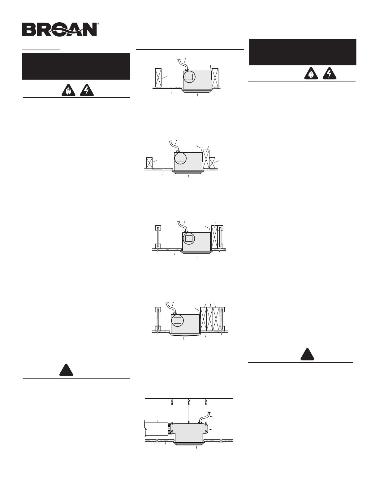
HOUSING MOUNTED DIRECTLY TO
CEILING JOIST OR WALL STUD
2x6 (or larger) Discharge parallel to joists or studs.
*
*
HOUSING MOUNTED TO 2x4 TRUSS
Requires additional framing for mounting tabs.
Discharge parallel to joists.
*
HOUSING MOUNTED TO “I” JOIST
Requires additional framing for mounting tabs.
Discharge parallel to joists.
*
HOUSING MOUNTED IN
ANY LOCATION BETWEEN JOISTS
Requires additional framing for mounting tabs.
* Additional framing must be a 2x6 (minimum height).
SUSPENDED CEILINGS
Housing hung with wires - 3-point mount.
INSTRUCCIONES
ADVERTENCIA
PARA REDUCIR EL RIESGO DE INCENDIO, DESCARGA ELÉCTRICA O LESIONES PERSONALES,
OBSERVE LO SIGUIENTE:
1. Utilice esta unidad solamente de acuerdo con las
instrucciones del fabricante. Si tiene preguntas
comuníquese con el fabricante a la dirección o al
número telefónico que se indica en la garantía.
2. Antes de dar servicio o limpiar la unidad, interrumpa
el suministro de energía en el panel de servicio y
bloquee los dispositivos de desconexión para evitar
la reinstalación accidental de la energía. Cuando no
se puedan bloquear los dispositivos de desconexión, fije seguramente en el panel de servicio un
medio de advertencia que sea visible, como por
ejemplo una etiqueta.
3. Una persona o personas calificadas deben realizar
el trabajo de instalación y el cableado eléctrico, de
acuerdo con todos los códigos y normas aplicables,
inclusive los códigos y normas de construcción
para evitar incendios.
4. Se necesita suficiente aire para que se realice la
combustión y la descarga de gases adecuadas
a través de la chimenea del equipo para quemar
combustible a fin de evitar las corrientes de inversión. Observe los lineamientos del fabricante del
equipo de calefacción y las normas de seguridad,
como por ejemplo las publicadas por la Asociación
Nacional de Protección contra Incendios (National
Fire Protection Association: NFPA), y la Sociedad
Americana de Ingenieros en Calefacción, Refrigeración y Sistemas de Acondicionamiento de Aire
(American Society for Heating, Refrigeration and
Air Conditioning Engineers: ASHRAE), y los códigos
locales.ditioning Engineers (ASHRAE), and the local
code authorities.
5. Cuando corte o perfore la pared o el cielo raso, tenga
cuidado de no dañar el cableado eléctrico ni otras
conexiones de servicios que se encuentren ocultas.
6. Los ventiladores con conductos siempre deben
tener salida hacia el exterior.
7. Si se va a instalar esta unidad en el cielo raso sobre
una tina o ducha, debe marcarse que es apropiada
para esta aplicación y conectarse a un GFCI (interruptor accionado por pérdida de conexión a tierra)
en un circuito de derivación protegido.
8. Nunca coloque el interruptor en un lugar en donde
se pueda alcanzar desde la tina o ducha.
9. Esta unidad debe conectarse a tierra.
PRECAUCIÓN
1. Esta unidad debe usarse solamente para ventilación general. No la utilice para la descarga de
materiales ni vapores peligrosos o explosivos.
2. Para evitar causar daño a los cojinetes del motor
y pistones impulsores ruidosos y/o no balanceados, mantenga los aerosoles para pirca, el polvo
de construcción, etc. lejos del motor.
3. Por favor consulte la información y los requerimientos adicionales contenidos en la
etiqueta de especificaciones que se encuentra
en el producto.
A la persona que realiza la instalación: Deje este manual con el dueño
de la casa.
Al dueño de la casa: Las instrucciones
de operación y limpieza se encuentran
en la página 4.
MOUNTING
TAB
GRILLE
SUSPENDED
CEILING MATERIAL
POWER
CABLE
4" ROUND
DUCT
HOUSING
ALETA DE
MONTAJE
REJILLA
MATERIAL DEL
TECHO SUSPENDIDO
CABLE
DE ALIMENTACIÓN
CONDUCTO
REDONDO DE
4" (10.2 CM)
CUBIERTA
5/8
1
1-1/4
ALETA DE
MONTAJE
REJILLA
MATERIAL DEL
TECHO SUSPENDIDO
CABLE
DE ALIMENTACIÓN
CONDUCTO
REDONDO DE
4" (10.2 CM)
CUBIERTA
INSTALACIONES TÍPICAS
CUBIERTA
VIGUETA
DEL
TECHO
O PARED
ALETAS DE
MONTAJE
REJILLA
MATERIAL DEL
TECHO O PARED
CABLE
DE ALIMENTACIÓN
CUBIERTA
ALETAS DE
MONTAJE
REJILLA
MATERIAL
DEL TECHO
CABLE
DE ALIMENTACIÓN
ESTRUCTURA
ADICIONAL*
VIGUETA O
VIGA DE
2x4 DE
CIELO
RASO
VIGUETA O
VIGA DE
2x4 DE
CIELO
RASO
CUBIERTA
CABLE DE ALIMENTACIÓN
VIGUETA
"
I
"
ALETAS DE
MONTAJE
MATERIAL
DE CIELO RASO
ESTRUCTURA
ADICIONAL
REJILLA
VIGUETA
"
I
"
CUBIERTA
CABLE DE ALIMENTACIÓN
VIGUETA
"
I
"
ALETAS DE
MONTAJE
MATERIAL
DEL TECHO
ESTRUCTURA
ADICIONAL*
REJILLA
VIGUETA
"
I
"
TYPICAL INSTALLATIONS
INSTALACIONES TÍPICAS
CUBIERTA MONTADA
DIRECTAMENTE EN LA VIGUETA
2x6 (o más grande). Descarga paralela a las viguetas.
*
CUBIERTA MONTADA EN UNA VIGA DE 2x4
Se requiere una estructura adicional para las aletas
de montaje. Descarga paralela a las viguetas.
*
CUBIERTA MONTADA EN UNA VIGUETA “I”
Se requiere una estructura adicional para las aletas
de montaje. Descarga paralela a las viguetas.
*
CUBIERTA MONTADA EN CUALQUIER
LUGAR ENTRE LAS VIGUETAS
Se requiere una estructura adicional
para las aletas de montaje.
* La estructura adicional debe ser un tramo de 2x6
(altura mínima).
Housing hung with wires - 3-point mount.
SUSPENDED CEILINGS
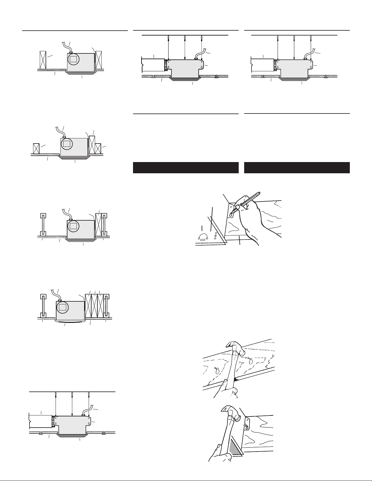
INSTALL THE HOUSING
THE FOLLOWING INSTALLATION ILLUSTRATIONS
SHOW 2 X 6 JOISTS OR STUDS. IF YOU HAVE A
TRUSS OR “I”-JOIST INSTALLATION, MOUNT THE
VENTILATOR TO THE ADDITIONAL FRAMING IN
THE SAME MANNER. (Additional framing must
be a 2x6 (minimum height).
1. Choose the location for your fan in the ceiling or wall. For best possible performance,
use the shortest possible duct run and a
minimum number of
elbows.
2. Position mounting
brackets against joist
or stud so that bottom
edge of housing will
be flush with finished
ceiling or wall.
Additional positioning
feature for 5/8”, 1”, &
1-1/4” thick ceiling or
wall material:
Holes in corners of housing are labeled with
various ceiling or wall material thicknesses.
Position housing so bottom edge of joist is
visible through a matched set of holes. The
housing is now in the proper position for that
ceiling or wall material thickness.
Additional positioning feature for 1/2” thick
ceiling or wall material:
Bend two tabs, on side of housing,
Lift housing until tabs contact underside of
joist or stud.
Mark the keyhole slot on both mounting
brackets.
3. Set housing aside and
drive nails partially into
joist or stud at the top of
both keyhole marks.
- PLEASE NOTE -
New Construction
HOLES
OROFICIOS
TAB
ALETA
BOTTOM EDGE OF JOIST
BORDE INFERIOR DE LA VIGUETA
900 outward.
Cubierta montada con cables. Montaje de tres puntos.
TECHOS SUSPENDIDOS
INSTALACIÓN DE LA CUBIERTA
LAS SIGUIENTES ILUSTRACIONES DE LA INSTALACIÓN
MUESTRAN VIGUETAS O MONTANTES DE 2 X 6. SI LA
INSTALACIÓN ES EN UNA VIGA O EN UNA VIGUETA
EN “I”, MONTE EL VENTILADOR EN LA ESTRUCTURA
ADICIONAL DE LA MISMA MANERA. (La estructura
adicional debe ser un tramo de 2x6 (altura mínima).
1. Seleccione la ubicación del ventilador con lámpara en
el cielo raso o pared. Para obtener el mejor rendimiento posible, utilice un tramo de conductos lo más corto
en las esquinas de la cubierta están marcados con varios
espesores del material del cielo raso o pared. Coloque la
cubierta de manera que el borde inferior de la vigueta sea
visible a través del conjunto de orificios que coinciden.
Ahora la cubierta se encuentra en la posición adecuada
para ese espesor del material del cielo raso o pared.
Característica adicional para la colocación en material
de cielo raso o pared de ½” (1.3 cm):
Doble a 90º y hacia afuera las dos aletas que se encuen-
tran a los costados de la cubierta. Levante la cubierta
hasta que las aletas entren en contacto con la cara
inferior de la vigueta or montante.
Marque el orificio con forma de cerradura de ambas
abrazaderas de montaje.
- POR FAVOR NOTE -
Construcción nueva
Construcción nueva
posible y un número mínimo de codos.
2. Coloque las abrazaderas de
montaje contra la vigueta o
montante, de manera que el
borde inferior de la cubierta
quede al ras del cielo raso o
pared terminado.
Característica adicional para la
colocación en material de cielo
raso o pared de 5/8” (1.6 cm),
1” (2.5 cm) y 1 ¼” (3.2 cm):
Los orificios que se encuentran
3. Coloque la cubierta a un lado
e introduzca parcialmente los
clavos en la vigueta o montante, en la parte superior de
ambas marcas de los orificios
en forma de cerradura.
Cubierta montada con cables. Montaje de tres puntos.
TECHOS SUSPENDIDOS
4. Hang housing from nails
and pound nails tight.
To ensure a noise-free
mount, pound another
nail through the top hole
of each mounting tab.
2
4. Suspenda la cubierta con
los clavos e introduzca los
clavos completamente. Para
asegurar un montaje sin
ruido, coloque otro clavo en el
orificio superior de cada aleta
de montaje.
 Loading...