

BRANT RADIANT HLV User Manual

!
HLV Series Tube Heater
Vacuum System
Design, Installation, Operation and Maintenance Manual
The HLV Series Infrared Tube Heater is a negative pressure, two stage radiant heater vacuum system
designed to provide comfort heat. Consisting of four main components; a burner control box, radiant tubes,
reflector assembly and vacuum exhauster, this system generates infrared energy to heat the objects in the
space. These objects then reradiate this heat, creating a comfort zone at the floor level. This is how large
spaces can be heated efficiently without having to provide primary infrared for every square foot of space.
For Your Safety
If you smell gas:
WARNING
Improper installation, adjustment, alteration, service or maintenance can cause
property damage, injury or death. Read the installation, operation and maintenance
instructions thoroughly before installing or servicing this equipment.
This heater must be installed and serviced by trained gas installation and service
personnel only. Failure to comply could result in personal injury, asphyxiation, death,
fire or property damage.
In locations used for the storage of combustible materials, signs must be posted to
specify the maximum permissible stacking height to maintain the required clearances
from the heater to the combustibles. Signs must either be posted adjacent to the
heater thermostats or in the absence of such thermostats, in a conspicuous location.
Not for residential use! Do not use this heater in the home, sleeping quarters,
attached garages, etc. Installation of a commercial tube heater system in
residential indoor spaces may result in property damage, serious injury,
asphyxiation or death.
• Do not try to light any appliance. • Immediately call your gas supplier from a neighbor’s phone.
• Do not touch any electrical switch. • Follow the gas supplier’s instructions.
• Do not use any phone in your building. • If you cannot reach your gas supplier, call the fire department.
Keep these instructions for future reference.
LIOHLV-Rev. 21711
Print: 2M-8/13_r1-5/14(CDS)
Replaces: LIOHLV-2M-6/12(CDS)

Table of Contents
HLV Series
Contents
1.0 Introduction . . . . . . . . . . . . . . . . . . . . . . . . . . . . . . . . . . . . . . . . . . . . . . . . . . . . . . . . . . . . . . . . . . . . 3
HLV Series Specifications ....................................................4
Approvals Standards and Certifications . . . . . . . . . . . . . . . . . . . . . . . . . . . . . . . . . . . . . . . . . 5
Safety Labels and Locations ..................................................6
Clearance to Combustibles ...................................................8
2.0 Design . . .....................................................................10
Pre-Design...............................................................10
Design for Non-Condensing Systems ..........................................11
Design for Condensing Systems ..............................................12
System Design Definitions...................................................14
Typical System Layouts.....................................................15
Vacuum Pump Application . . . . . . . . . . . . . . . . . . . . . . . . . . . . . . . . . . . . . . . . . . . . . . . . . . 18
Damper Application ........................................................19
3.0 Installation ....................................................................20
Pre-Installation ............................................................20
Vacuum Pump Assembly and Mounting ........................................21
Tube Assembly and Mounting ................................................23
Elbows and Intersections....................................................25
Baffle Assembly and Placement . . . . . . . . . . . . . . . . . . . . . . . . . . . . . . . . . . . . . . . . . . . . . . 27
Reflector Assembly . . . . . . . . . . . . . . . . . . . . . . . . . . . . . . . . . . . . . . . . . . . . . . . . . . . . . . . . 28
Burner Assembly and Mounting . . . . . . . . . . . . . . . . . . . . . . . . . . . . . . . . . . . . . . . . . . . . . . 30
Flue Venting..............................................................31
Combustion Air Requirements . . . . . . . . . . . . . . . . . . . . . . . . . . . . . . . . . . . . . . . . . . . . . . . 33
Electrical Requirements.....................................................34
Gas Supply . . . . . . . . . . . . . . . . . . . . . . . . . . . . . . . . . . . . . . . . . . . . . . . . . . . . . . . . . . . . . . 39
4.0 Operation . . . . . . . . . . . . . . . . . . . . . . . . . . . . . . . . . . . . . . . . . . . . . . . . . . . . . . . . . . . . . . . . . . . . . 42
Lighting and Shutdown .....................................................42
Sequence of Operation .....................................................42
Thermostat...............................................................43
Diagnostics . . . . . . . . . . . . . . . . . . . . . . . . . . . . . . . . . . . . . . . . . . . . . . . . . . . . . . . . . . . . . . 43
System Start-Up Pre-Checks . . . . . . . . . . . . . . . . . . . . . . . . . . . . . . . . . . . . . . . . . . . . . . . . 44
Damper Adjustment ........................................................44
5.0 Maintenance ...................................................................45
Routine Inspection.........................................................45
Troubleshooting Guide......................................................46
Replacement Parts . . . . . . . . . . . . . . . . . . . . . . . . . . . . . . . . . . . . . . . . . . . . . . . . . . . . . . . . 50
6.0 Limited Warranty . . . . . . . . . . . . . . . . . . . . . . . . . . . . . . . . . . . . . . . . . . . . . . . . . . . . . . . . . . . . . . . 52
2

HLV Series
1.0 Introduction • Overview • System Components
1.0 Introduction
Overview
The intent of this manual is to provide information regarding general safety, installation, operation and
maintenance of the tube heater vacuum system. You must read, and understand, the instructions and
safety warnings in this manual before installing the heating system.
System Components*
Prior to installation, verify that the heater’s gas type and voltage (as listed on the rating plate) match that of
your application. Also verify that you have received all heater contents included with your system by
checking them against the packing list. Materials not included in the heater kit contents (e.g., screws, vent
material, terminals, etc.) are the responsibility of the installer. Notify your product representative or Detroit
Radiant Products of any discrepancy or missing kit contents prior to installing unit.
Figure 1.1 • Typical System Components*
* Each HLV Series vacuum system
is engineered specific to each
application’s design parameters.
Some items illustrated may not be
required with your system.
Tube H a ng er
Chain Set
Reflector End
Turnbuckle.
Burner Control Box
16” Burner Tube
Cap w/Clips
Reflector Center
Reflector
Tension Spring
Tube Clamp
Support
Standard
Reflector
Isolation Boot
Primary/Secondary
Combustion Chamber(s)
Radiant
Tube (s)
Baffles
SS Flex Connector
Damper
Ignitor/
Sensor Box
Vacuum Pump
Shut-off Valve
Refer to pages 50-51 for a complete parts breakdown.
3
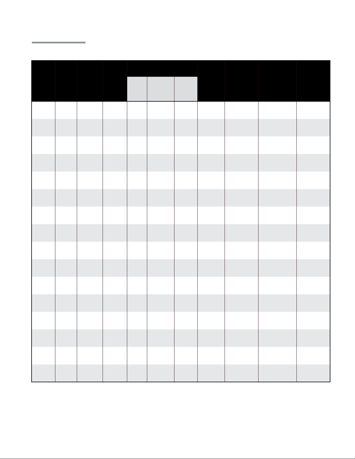
1.0 Introduction • HLV Series Specifications
Specifications
Chart 1.1 • HLV Series Specifications
Approximate System
Hanging Weights
Burner
Model
Gas
Types
BTU/H
(High Fire)
BTU/H
(Low Fire)
Per
Burner
Head
Per 10 Ft.
Radiant Pipe
& Reflector
Section
Per 10 Ft.
Tailpipe &
Reflector
Section
Typical
Mounting
Height^
Combustion
Chamber
(Black Coated)
Radiant
Emitter
Tube (s)* *
HLV Series
Condensing
Pipe
HLV- 40 *
HLV- 5 0*
HLV- 60
HLV-75
HLV- 80
HLV- 9 0
HLV-100
HLV-110
HLV-120
HLV-125
N or P
N or P
N or P
N or P
N or P
N or P
N or P
N or P
N or LP
N or P
40,000 40,000
50,000 50,000
60,000 50,000
75,000 60,000
80,000 64,000
90,000 72,000
100,000 80,000
110,000 88,000
120,000 96,000
125,000 100,000
35 lbs. 35 lbs. 45 lbs.
35 lbs. 35 lbs. 45 lbs.
35 lbs. 35 lbs. 45 lbs.
35 lbs. 35 lbs. 45 lbs.
35 lbs. 35 lbs. 45 lbs.
35 lbs. 35 lbs. 45 lbs.
35 lbs. 35 lbs. 45 lbs.
35 lbs. 35 lbs. 45 lbs.
35 lbs. 35 lbs. 45 lbs.
35 lbs. 35 lbs. 45 lbs.
9’ to 14’
9’ to 14’
10’ to 15’
11’ to 18’
11’ to 18’
12’ to 20’
12’ to 20’
13’ to 23’
13’ to 25’
14’ to 27’
Al-Ti
Al-Ti
Al-Ti
Al-Ti
Al-Ti
Al-Ti
Al-Ti
Al-Ti
Al-Ti
Al-Ti
Coated Alum or
Uncoated HRT
Coated Alum or
Uncoated HRT
Coated Alum or
Uncoated HRT
Coated Alum or
Uncoated HRT
Coated Alum or
Uncoated HRT
Coated Alum or
Uncoated HRT
Coated Alum or
Uncoated HRT
Coated Alum or
Uncoated HRT
Coated Alum or
Uncoated HRT
Coated Alum or
Uncoated HRT
304 Stainless
Steel
304 Stainless
Steel
304 Stainless
Steel
304 Stainless
Steel
304 Stainless
Steel
304 Stainless
Steel
304 Stainless
Steel
304 Stainless
Steel
304 Stainless
Steel
304 Stainless
Steel
HLV-140
HLV-150
HLV-170
HLV-175
HLV-180
HLV-20 0
N or P
N or P
N or P
N or P
N or P
N or P
140,000 112,000
150,000 120,000
170,000 136,000
175,000 140,000
180,000 144,000
200,000 160,000
35 lbs. 35 lbs. 45 lbs.
35 lbs. 35 lbs. 45 lbs.
35 lbs. 35 lbs. 45 lbs.
35 lbs. 35 lbs. 45 lbs.
35 lbs. 35 lbs. 45 lbs.
35 lbs. 35 lbs. 45 lbs.
15’ to 30’
15’ to 30’
16’ to 40’
17’ to 42’
18’ to 47’
19’ to 50’
Al-Ti
Al-Ti
Al-Ti
Al-Ti
Al-Ti
Al-Ti
Coated Alum or
Uncoated HRT
Coated Alum or
Uncoated HRT**
Coated Alum or
Uncoated HRT**
Coated Alum or
Uncoated HRT**
Coated Alum or
Uncoated HRT**
Coated Alum or
Uncoated HRT**
304 Stainless
Steel
304 Stainless
Steel
304 Stainless
Steel
304 Stainless
Steel
304 Stainless
Steel
304 Stainless
Steel
* The HLV-40 and HLV-50 do not have a reduction for low fire.
** All systems are designed to utilize either black coated aluminized steel (Alum) or uncoated hot-rolled steel (HRT)
radiant emitter tubes. On systems designed with the hot-rolled steel option, a coated aluminized steel radiant tube
(TP-26A) must be installed immediately downstream of the titanium stabilized aluminized steel (Al-Ti) combustion
chamber (TP-26B) on burner models HLV-150, 170, 175, 180 and 200 only.
^ Recommended mounting heights are provided as a guideline. Actual conditions may dictate variations from this data.
NOTE: Burner models HLV-170, 175, 180 and 200 receive TP-220 stainless steel tube clamp.
4

HLV Series
!
1.0 Introduction • Approval Standards and Certifications • Applications
Approval Standards and Certifications
Installation of this tube heater must comply with all applicable local, state and national specifications,
regulations and building codes. Contact the local building inspector and/or fire Marshall for guidance.
In the absence of local codes, the installation must conform to the latest edition of:
United States: National Fuel Gas Code, ANSI Z223.1 (NFPA 54).
Canada: CAN/CGA B149.1 and .2, Canadian Electrical Code C22.1.
• ANSI Z83.20b - American National Standards Institute.
• OSHA - Occupational Safety & Health Administration.
• CSA - Canadian Standards Association.
• Indoor approval.
Applications
WARNING
Not For Residential Use. Installation of a commercial tube heater system in residential indoor spaces
may result in property damage, serious injury or death.
This is not an explosion proof heater. No tube heater may be used in a Class 1 or Class 2 Explosive
Environment. Consult your local Fire Marshall, insurance carrier and other authorities for approval if the
proposed installation is in question.
Commercial/Industrial: Unless otherwise indicated, tube heaters are designed and certified for use in
industrial and commercial buildings, such as warehouses, manufacturing plants, aircraft hangars and
vehicle maintenance shops. For maximum safety the building must be evaluated for potential problems
before installing the heating system. A critical safety factor to consider before installation is the clearance
to combustibles (see pgs. 8-9).
Public Garages: Installation of this tube heater in public garages must conform with the Standard for
Parking Structures NFPA 88A (latest edition) or the Code for Motor Fuel Dispensing Facilities and Repair
Garages NFPA 30A (latest edition).
• Heaters must not be installed less than 8 ft. (2.4M) above the floor. Minimum clearances to
combustibles must be maintained from vehicles parked below the heater.
• When installed over hoists, minimum clearances to combustibles must be maintained
from the upper most point of objects on the hoist.
Aircraft Hangars: Installation of this tube heater in aircraft hangars must conform with the Standard for
Aircraft Hangars, ANSI/NFPA 409 (latest edition).
• In areas adjoining the aircraft storage area (e.g., shops, offices) the bottom of heaters shall be
installed no less than 8 ft. (2.4M) above the floor.
• Suspended or elevated heaters shall be located in spaces where they shall not be subject to damage
by aircraft, cranes, movable scaffolding or other objects.
High Altitude: Installation of this tube heater is approved, without modifications, for elevations up to 6,000
feet (1,829M) MSL (sea level) in the United States. Contact the factory for installations above these
elevations.
5

1.0 Introduction • Safety Labels and Locations
HLV Series
Read and understand all safety information and warnings in this manual before installation,
operation and maintenance of the radiant tube heater system.
Safety Labels and Their Locations
Safety warning labels must be maintained on the heating system. Safety labels and their locations are
illustrated below and on page 7. Product safety signs or labels should be replaced by the product user
when they no longer are legible.
It is important to provide warnings to alert individuals to potential hazards and safety actions. ANSI
Z83.20b and CSA 2.34 requires you to post a sign near the heater’s thermostat, or in absence of such
thermostat, in a conspicuous location “specifying the maximum permissible stacking height to maintain
the required clearances from the heater to combustibles.” A Clearance Safety Limit Tag (F/N: LL01) is
provided with each burner control box (see p.7). Contact Detroit Radiant Products Company or an
authorized distributor for obtaining safety signs or replacement labels and tags.
Top Panel
HLV-40-125N
HLV-125
Production Code:
5.05
Version:
Data on this label is for the model shown on this label. If your heater has been converted, this
information is not accurate. Please contact the factory for assistance.
BURNER COMPONENTS:
Gas Valve:
Circuit Board:
Wire Harness:
N.O. Switch:
N.O. VL Orifice:
N.C. Switch:
N.C. VL Orifice:
Diff Switch:
Diff VL Orifice:
Igniter:
Burner:
16” Tube:
Ind. Lights:
HEATER
TYPE:
C1
For parts replacement information, contact factory at 586-756-0950 or visit www.drp-co.com/parts.
(Specify TP-#’s)
36G54-224-N
6465H
3 PCS Harness
None
None
None
None
IS22016051F5169
Grey (+ / -)
SAMPLE
Norton
High
4” Stnd.
Yellow - 24V
Orifice Type:
Gas:
TP-204#
Air:
1 1/2”
TP-44#31 5/8”
1540A
1251
3-PCS Harness
N/A
N/A
264E
50
201B
380
828
C1 C2 C3
3
Serial No.: 0807XXXXXXXXXX 0001
None
Stock:
Add-On:
N/A
Red LED
Diag. Light:
None
Term. Block:
40 VA
Transformer:
Fasco Lg.
Fan:
50Hz - 120V
Alt. Fan:
When Specified
Alt. Fan Usage:
Picker x2
Relay:
None
Filter:
3 T-plug
24 Volt In:
2x4 Box
120 Volt In:
7/8” FC
Gas In:
None
Extra VL Orifice:
Internal Use Only:
Electric:
1
LLWT038
Tag:
1 5/8”
None
Special 1:
Special 2:
F/N: LLTCL012 Clearance to
Combustibles Label.
827
N/A
826
55A
55B
1527
N/A
832
66
83
Burner Control Box
17
Component Label
1 7/16”
(located under the top panel)
Bottom Panel
F/N: LLLOGO1
6

HLV Series
- 120V HEATER INPUT -
Air Metering Orifice
DO NOT REMOVE
TP-114
TP-3014
3”
SAMPLE
1.0 Introduction • Safety Labels and Locations
F/N: LLAC
Air Metering Orifice
120V
F/ N: LLV3EP1
(Controls Compartment)
HOT
NEUTRAL
EARTH
Left Panel
Back Panel
HOT
NEUTRAL
120V
EARTH
- 120V HEATER INPUT -
RE-VERBER-RAY INFRA-RED RADIANT TUBE HEATER
®
FOR OUTDOOR USE AND INDOOR (Non-Residential) INSTALLATION ONLY.
Class IIIA Permanent Label
MODEL NO.
HLV-40-125N
Volts AC:
120V - 60Hz
AMPS - Starting:
4.8
AMPS - Running:
1.1
Combustion Chamber:
4” Black Coated Aluminized
DESIGN COMPLIES WITH:
ANSI Z83.20b-2004-GAS FIRED LOW INTENSITY INFRA-RED HTR.
DETROIT RADIANT PRODUCTS COMPANY
21400 HOOVER ROAD - WARREN, MI
(586) 756-0950 - www.drp-co.com
INPUT BTU/H
125,000 / 95,000
Manifold Pressure:
3.5 in.
Maximum Inlet Pressure:
14 in.
Minimum Inlet Pressure:
5.0 in.
SAMPLE
For stainless steel upgrades: The combustion tube is 409 Series stainless steel.
F/N: LLTB018 (Natural Gas)
F/N: LLTB019 (LP Gas)
FOR USE WITH
Natural Gas
W.C.P.
W.C.P.
W.C.P.
Heater Type
C1
Minimum Mounting Angle:
045DEGREES
Maximum Mounting Angle:
DEGREES
Serial No.: 0807XXXXXXXXXX 0001
Rating Plate
F/ N: LLV3EP2
Orange Crescent
Right Panel
(Valve Compartment)
F/N: LL01 - Clearance Safety Limit Tag
(Affix adjacent to heater’s thermostat)
16” Burner Tube
SERVICE ACCESS PANEL
IGNITER & FLAME SENSE COMPARTMENT
1. Turn off gas & electricity.
2. Remove cover by lifting top
cover upward and outward.
CAUTION: HOT SURFACE.
KEEP COVER IN PLACE. REMOVE FOR SERVICE ONLY.
SERVICE ACCESS PANEL
IGNITER & FLAME SENSE COMPARTMENT
1. Turn off gas & electricity.
2. Remove cover by lifting top
cover upward and outward.
CAUTION: HOT SURFACE.
KEEP COVER IN PLACE. REMOVE FOR SERVICE ONLY.
F/N: LLTB026
F/N: LLV2EP9
Combustion
Chamber
!
INSTALLER
F/ N: LLV2EP15
Radiant
Tube
AVOID EQUIPMENT FAILURE
THIS 10 FT. TUBE IS THE
COMBUSTION CHAMBER.
The combustion chamber utilizes either 409
stainless, titanium alloy or aluminized steel -
depending on the model number of your heater.
THIS TUBE MUST BE THE FIRST TUBE
FOLLOWING THE BURNER CONTROL BOX.
Rotate the tube’s welded seam to bottom.
Consult the manual(s) for further details.
F/N: LLTB004 (orange)
7

!
!
1.0 Introduction • Clearance to Combustibles
HLV Series
Clearance to Combustibles
WARNING
Failure to maintain minimum clearance to combustibles may result in fire and/or explosion,
property damage, serious injury or death. Always maintain minimum clearances and post
clearance safety limit signs or the clearance safety tag where needed.
Clearance to combustibles is defined as the minimum distance that must exist between the tube surface,
or reflector, and any combustible items (see Figure 1.2). It also pertains to the distance that must be
maintained from moving objects around the tube heater. Moving items include, but are not limited to,
vehicle lifts, overhead doors, cranes and hoists. For instance, if vehicle lifts are present, ensure that
clearances will be maintained from the highest raised vehicle.
If you are unsure of the potential hazards in the application, consult your local fire Marshall, fire insurance
carrier or other qualified authorities on the installation and approval of the proposed installation.
WARNING
Placement of explosive objects, flammable objects, liquids and vapors close to
the heater may result in explosion, fire, property damage, serious injury or death.
Do not store or use explosive objects, liquids or vapor in the vicinity of the heater.
Clearances listed in Chart 1.2 apply to each individual burner in the HLV system. When installing the
tube heater vacuum system, clearances to combustibles for each burner model and its applicable tube
run must be maintained. Inspect each burner rating label to ensure that clearances are maintained.
In locations used for the storage of combustible materials, signs must be posted to specify the
maximum permissible stacking height to maintain the required clearances from the heater to
combustibles. Signs must be posted adjacent to the heater’s thermostats or, in the absence of such
thermostats, in a conspicuous location.
The stated clearance to combustibles represents a surface temperature of 90°F (32°C) above room
temperature. Building materials with a low heat tolerance (such as plastics, vinyl siding, canvas, tri-ply,
etc.) may be subject to degradation at lower temperatures. It is the installer’s responsibility to assure that
adjacent materials are protected from degradation.
Figure 1.2 • Mounting Angles
0° Mounting Angle
with 2 Side Shields
(P/N: SSE)
Top
0° Mounting Angle 45° Mounting Angle
Top
Top
0° Mounting Angle
with 1 Side Shield
(P/N: SSE)
Top
Side
Below
Side
Front
Below
Behind
Front Behind
Below
8
Side Side
Below
HLV Series
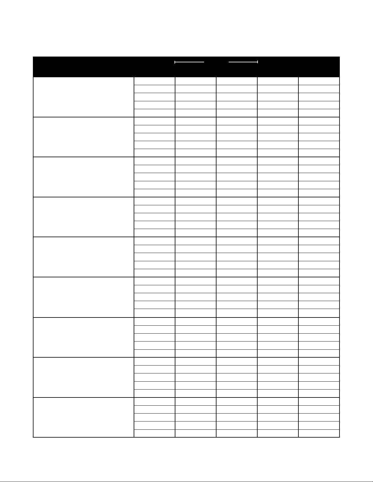
1.0 Introduction • Clearance to Combustibles
Chart 1.2 • Clearance to Combustibles in Inches (see Figure 1.2 for Mounting Angles)
Mounting
Model Number
HLV-40, HLV-50 [N, P]
with 1 side shield 0° 29 8 4 47
with 2 side shields 0° 9 9 4 47
20 ft. from burner 0° 7 7 4 30
HLV-60, HLV-75 [N, P]
with 1 side shield 0° 29 8 4 48
with 2 side shields 0° 9 9 4 48
20 ft. from burner 0° 7 7 4 30
HLV-80 [N, P]
with 1 side shield 0° 29 8 4 48
with 2 side shields 0° 16 16 4 48
20 ft. from burner 0° 7 7 4 30
HLV-90 [N, P]
with 1 side shield 0° 29 8 4 54
with 2 side shields 0° 16 16 4 54
20 ft. from burner 0° 7 7 4 30
HLV-100 [N, P]
with 1 side shield 0° 29 8 4 66
with 2 side shields 0° 16 16 4 66
20 ft. from burner 0° 7 7 4 30
HLV-110, HLV-120, HLV-125 [N, P]
with 1 side shield 0° 42 8 4 72
with 2 side shields 0° 20 20 4 72
20 ft. from burner 0° 7 7 4
HLV-140, HLV-150 [N, P]
with 1 side shield 0° 42 8 6 81
with 2 side shields 0° 30 30 6 81
20 ft. from burner 0° 11 11 6 44
HLV-170, HLV-175 [N, P]
with 1 side shield 0° 50 8 6 92
with 2 side shields 0° 30 30 6 92
20 ft. from burner 0° 11 11 6 44
HLV-180, HLV-200 [N, P]
with 1 side shield 0° 54 8 6 94
with 2 side shields 0° 30 30 6 94
20 ft. from burner 0° 11 11 6 44
Heaters mounted on an angle between 0° to 45° must maintain clearances posted for 0° or 45°; whichever is greater.
*
The top clearance of an exposed tube connection to combustibles is 18 inches.
**
Angle*
0° 9 9 4 47
45° 39 8 10 47
0° 9 9 4 48
45° 39 8 10 48
0° 11 11 4 48
45° 39 8 10 48
0° 12 12 4 54
45° 39 8 10 54
0° 14 14 4 66
45° 39 8 10 66
0° 18 18 4 72
45° 58 8 10 72
0° 24 24 6 81
45° 58 8 10 81
0° 34 34 6 92
45° 63 8 10 92
0° 41 41 6 94
45° 63 8 10 94
Front Behind Top** Below
Sides
30
9

2.0 Design • Pre-Design
HLV Series
2.0 Design
Pre-Design for Condensing and Non-Condensing Systems
The HLV Series vacuum system can be designed as a non-condensing or a condensing system.
After reviewing the following pre-design guidelines, proceed to the appropriate section for the desired
system. If it is uncertain as to what type of system should be used, begin by designing for a
condensing system, p.12. If the completed design does not require condensing pipe then, by default,
the system will become a non-condensing system.
1 Most non-condensing systems should be controlled via a single temperature zone. If two zones are
required, it may be necessary (in most cases) that the system be designed as a condensing system
(p.12). Contact factory for additional guidelines.
2 Determine the heat load requirement of the building.
3 Available mounting heights and coverage are the two most critical variables in burner selection and
quantity.
• The mounting height of the system determines the largest burner model that can be used.
• As the design is calculated, and if it is discovered that the quantity of burners in the system will not
provide sufficient coverage, it may be necessary to use a larger quantity of lower input burners.
4 When determining system location, clearance to combustibles must be maintained. Items such as
lights, sprinkler heads, overhead doors, storage areas containing stacked materials, gas and
electrical lines, parked vehicles, cranes, and any other possible hazards must be taken into account.
Refer to Chart 1.2, p.9 for Clearance to Combustibles distances.
IMPORTANT: Fire sprinkler heads must be located at an appropriate distance from the heater.
This distance may exceed the published clearance to combustibles as posted on the heater.
Certain applications may require the use of high temperature sprinkler heads or relocation of the
heaters.
Sprinkler systems containing propylene glycol or other potentially flammable substances are not
to be used in conjunction with this heater without careful consideration for and avoidance of
potential fire or explosion hazards. For further information consult NFPA 13.
5 Reference p.14 for System Design Definitions.
10
HLV Series
2.0 Design • Design for Non-Condensing Systems
Design for Non-Condensing Systems
System tube lengths are determined by the gas input (BTU/h) of each burner. Chart 2.1 below indicates
system design parameters for each burner model used in each system. When calculating tube lengths,
do not add in elbow and tee fittings as they have been accounted for.
Designing a non-condensing system can be fairly straightforward given the following steps are read
carefully. In addition to these steps, an understanding of the design definitions is critical. Refer to p.14
for these terms and illustrations.
1 Begin by designing a tentative layout without regard to design parameters. Use this approach to
place each burner and the vacuum pump where most desired (refer to Figures 2.4 - 2.10 for typical
layouts).
2 Once a tentative layout has been established, confirm that each run in the system meets the criteria
for ‘Calculated Minimum Run’. ‘Calculated Minimum Run’ is determined by adding the total ‘Single
Flow’ plus one-half of the ‘Common Flow’.
• If the system does not meet the ‘Calculated Minimum Run’, length must be added to the run until
all burners meet the design parameters.
• If the run exceeds the ‘Calculated Maximum Run’, it will be necessary to either make the system a
condensing system or shorten the runs which exceed this criteria.
3 Confirm the following applies (non-condensing systems only):
a) A maximum of two elbows per run is allowed per system.
b) A maximum of three intersections (tees or crosses) are allowed per system.
c) All elbows and intersections less than 20 feet from a burner require a reflector.
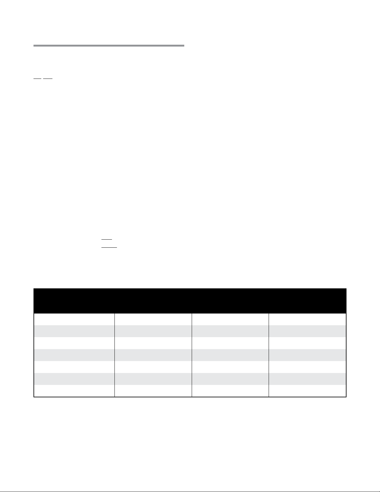
Chart 2.1 • Design Parameters for Non-Condensing Systems (refer to page 14 for definitions).
Minimum Distance from
Burner to First Elbow or
HLV Burner Model
HLV- 40 , H LV- 5 0 , H LV- 6 0
HLV-75, HLV- 80
HLV- 90 , HLV-100
HLV-110, HLV-120, HLV-12 5
HLV-140, HLV-150
HLV-170, H LV-175 , H LV-180
HLV-2 0 0
Intersection
10 ft. 30 ft. 60 ft.
10 ft. 35 ft. 65 ft.
10 ft. 40 ft. 70 ft.
10 ft. 45 ft. 75 ft.
15 f t. 50 ft. 80 ft.
15 f t. 55 ft. 85 ft.
20 ft. 60 ft. 90 ft.
* Be sure to account for runs where Tandem Tee Set (V-TTS) are used in the system.
NOTE: Contact the factory for approval when system design exceeds the guidelines set forth in the
table above.
Calculated
Minimum Run*
Calculated
Maximum Run*
11
2.0 Design • Design for Condensing Systems
HLV Series
Design for Condensing Systems
System tube lengths are determined by the gas input (BTU/H) of each burner. Chart 2.2 below
indicates system design parameters for each burner model used in each system. When calculating
tube lengths, do not add in elbow and tee fittings as they have been accounted for.
Designing a condensing system can be fairly straightforward given the following steps are read carefully.
In addition to these steps, an understanding of the design definitions is critical. Refer to p.14 for these
terms and illustrations.
1 Begin by designing a tentative layout without regard to design parameters. Use this approach to
place each burner and the vacuum pump where most desired (refer to Figures 2.4 - 2.10 for typical
system layouts).
2 Once a tentative layout has been established, confirm that each run in the system meets the criteria
for ‘Calculated Minimum Run’. ‘Calculated Minimum Run’ is determined by adding the total
‘Single Flow’ plus one-half of the ‘Common Flow’.
• If the system does not meet the ‘Calculated Minimum Run’, length must be added to the run until
all burners meet the design parameters.
3 Refer to Chart 2.2 to determine the ‘Calculated Starting Point of Condensing Run’ for each individual
burner run. All elbows and intersections that fall within the condensing section of run, must also
utilize condensing pipe. If there are no runs long enough to utilize condensing pipe, then the system
is regarded as a non-condensing system.
IN-LINE SYSTEMS: If the system requires the simulation of in-line burners, all tie-in burners
(Figure 2.1) must be located no less than the ‘Minimum Distance from Burner to First Elbow or
Intersection’; also reference ‘Maximum Actual Distance Between Tie-Ins for Simulated In-Line
Systems’ to ensure the tie-in distance is not exceeded. Reference Chart 2.2 to determine the
‘Starting Point for Condensing for Simulated In-Line Systems’.
skip to step 5
.
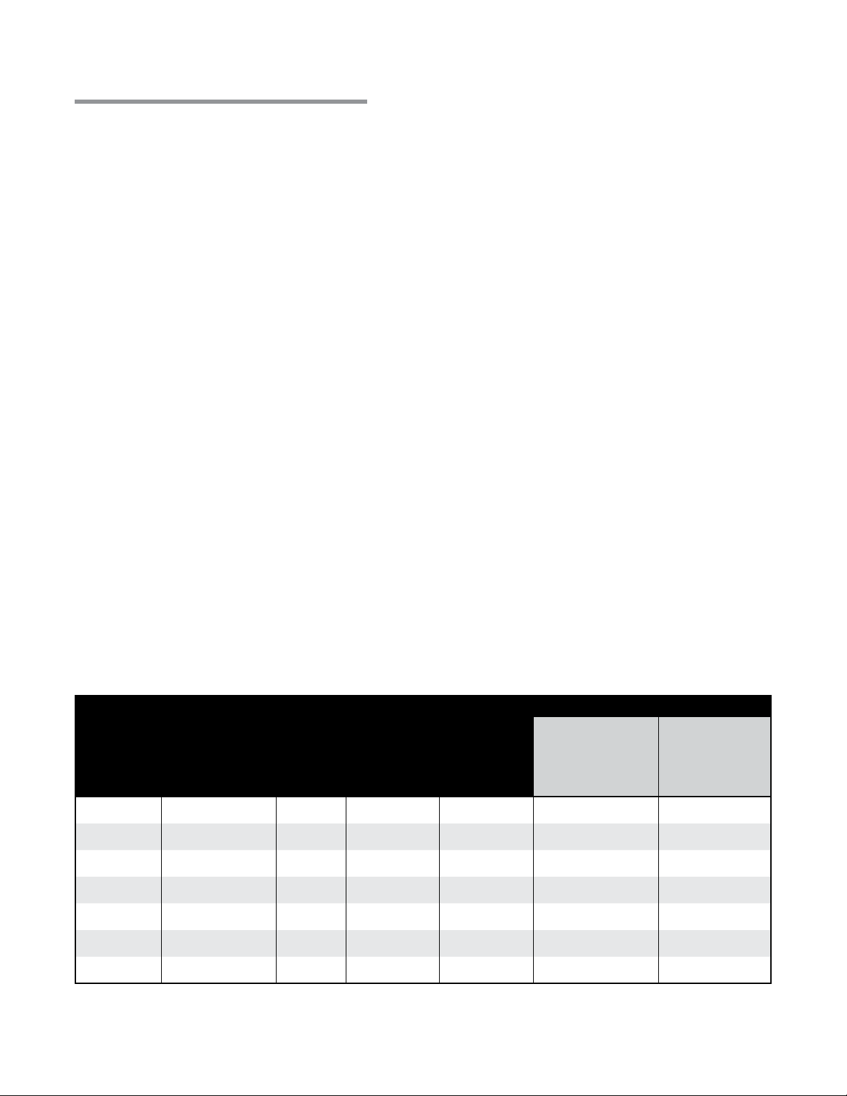
Chart 2.2 • Design Parameters for Condensing Systems (refer to page 14 for definitions).
HLV Burner
Model
40, 50, 60
75, 80
90, 100
Minimum
Distance from
Burner to First
Elbow or
Intersection (Ft.)
10 30 60 175 50 40
10 35 65 200 55 50
10 40 70 200 60 50
Calculated
Minimum
Run (Ft.)**
Calculated
Starting Point
of Condensing
Run (Ft.)
Calculated
Maximum Run
(Including
Condensing
Pipe) (Ft.)
When using an in-line approach,
Simulated In-Line Systems*
Starting Point
Maximum Actual
Distance Between
Tie-Ins for Simulated
In-Line Systems (Ft.)
(after last tie-in)
for Condensing for
Simulated In-Line
Systems (Ft.) .
110, 120, 125
140, 150
170, 175, 180
200
10 45 75 225 65 60
15 50 80 225 70 60
15 55 85 250 75 70
20 60 90 250 80 70
NOTE: Contact the factory for approval when system design exceeds the guidelines set forth in the
table above.
used in the system.
* Actual run; not calculated. **Be sure to account for runs where Tandem Tee Set (V-TTS) are
12

HLV Series
2.0 Design • Design for Condensing Systems
4 Measure the ‘Calculated Minimum Run’ for each burner. It is generally recommended to shorten
runs which exceed the ‘Calculated Maximum Run’. Refer to Figures 2.2 & 2.3 on p.14 for
examples of determining ‘Calculated Maximum Run’.
5 TEMPERATURE ZONES: In systems where dual zones will be used to control burners on separate
thermostats, the following guideline must be met:
a) Condensing pipe must begin at the point where two runs (operating on separate zones)
share common tubing; continuing to the pump. See Figure 2.1.
6 Confirm the following applies (condensing systems only):
a) A maximum of three elbows per run is allowed per system.
b) A maximum of six intersections (tees or crosses) are allowed per system.
c) All elbows and intersections less than 20 feet from a burner requires a reflector.
Figure 2.1 • Condensing Pipe for Dual Zone Systems and Simulated In-Line Burners
T
Zone 1
Condensing Pipe
Points where zone 1 & 2 share
common tubing. Condensing
pipe must begin here.
Condensing Pipe
Zone 2
T
Tie-In Burner
13

2.0 Design • System Design Definitions
HLV Series
System Design Definitions
Calculated Maximum Run:
The longest allowable ‘Calculated Run’ from any burner to the vacuum pump, including condensing pipe.
Calculated Minimum Run:
The shortest allowable ‘Calculated Run’ from any burner (including V-TTS Tandem Tee runs) to the vacuum pump,
including condensing pipe.
Calculated Run ***read carefully***:
Calculated run is determined by adding the total ‘Single Flow’ plus one-half of the ‘Common Flow’ of tubing/pipe
from any burner to the vacuum pump.
Calculated Starting Point of Condensing Run:
The point in the ‘Calculated Run’ where condensing pipe must begin. See Figure 2.3.
Common Flow:
The tube/pipe in a run between the first intersection (tee or cross) and the vacuum pump. ‘Common Flow’ begins
at the point where two or more burners share common tube/pipe. See Figure 2.2.
Minimum Distance to Elbow or Intersection:
The minimum allowable distance from a burner to the first elbow or intersection.
Run:
The total actual length of tube/pipe from an individual burner to the vacuum pump.
Single Flow:
The tube/pipe in a run from the burner to the first intersection (tee or cross). See Figure 2.3.
Figure 2.2 • Single and Common Flow
Vacuum Pump
20 ft.
HLV-7 5
Single Flow Single Flow
30 ft. 30 ft.
Common Flow
HLV-7 5
Figure 2.3 • Starting Point of Condensing Pipe
40 ft. 40 ft.
HLV-7 5 HLV-7 5
40 ft.
Starting Point of Condensing
20 ft.
Vacuum Pump
14

HLV Series
2.0 Design • Typical System Layouts
Typical System Layouts
The following pages illustrate the most common system layouts and their applications. The layouts
shown are just a few of many designs. A particular application may call for a design that is unique to
match its’ particular building requirements. In any case, these layouts should serve as a starting point
for the design in many applications. NOTE: Figures 2.4 - 2.10 are provided for illustrative purposes only
and must not supersede any design parameters set forth in this manual.
Figure 2.4 • Typical Layout A
These layouts are typically designed for fire stations, service garages, bus garages, arenas and aircraft hangars.
Figure 2.5 • Typical Layout B
This layout is typical in service garages,
warehouses, manufacturing plants, greenhouses
and where even heat distribution is a necessity.
Figure 2.6 • Typical Layout C
This layout is for use in small remote bay
areas or small service garage apparatus
bays.
15

2.0 Design • Typical System Layouts
HLV Series
Figure 2.7 • Typical Layout D
These systems are typically found in large buildings with long runs where roof penetrations are not desired.
These layouts are normally designed for perimeter mounting such as indoor tracks, distribution centers, postal
centers or aircraft hangars.
16
 Loading...