

Page 1

!
Detroit Radiant Products Co.
Tube Heater
General Manual
To be used in conjunction with Series 3 insert manuals.
WARNING
Improper installation, adjustment, alteration, service or maintenance can cause
property damage, injury or death. Read and understand the installation, operating
and maintenance instructions thoroughly before installing or servicing this equipment.
This heater must be installed and serviced by trained gas installation and service
personnel only. Failure to comply could result in personal injury, asphyxiation, death,
fire and/or property damage.
In locations used for the storage of combustible materials, signs must be posted to
specify the maximum permissible stacking height to maintain the required clearances
from the heater to the combustibles. Signs must either be posted adjacent to the
heater thermostats or in the absence of such thermostats, in a conspicuous location.
For Your Safety
If you smell gas:
• Do not try to light any appliance. • Immediately call your gas supplier from a neighbor’s phone.
• Do not touch any electrical switch. • Follow the gas supplier’s instructions.
• Do not use any phone in your building. • If you cannot reach your gas supplier, call the fire department.
INSTALLER: Present this manual to the end user.
Keep these instructions in a clean and dry place for future reference.
Model#: ___________________ Serial #: _________________________
(located on rating label)
Print:5M-8 /13_r2-5/14 (CDS)
Replaces:LIOGT3-2M-4/13 (CDS)
Form: LIOGT3-10211
Page 2

Contents
1.0 Introduction . . . . . . . . . . . . . . . . . . . . . . . . . . . . . . . . . . . . . . . . . . . . . . . . . . . . . . . . . . . . . . 3
Overview ............................................................3
Heater Components . . . . . . . . . . . . . . . . . . . . . . . . . . . . . . . . . . . . . . . . . . . . . . . . . . . 3
2.0 Safety . . .................................................................4
Warning Symbols . . . . . . . . . . . . . . . . . . . . . . . . . . . . . . . . . . . . . . . . . . . . . . . . . . . . . 4
Applications ..........................................................4
Clearance to Combustibles ..............................................5
Safety Signs and Labels ................................................5
Venting..............................................................6
Gas Supply . . . . . . . . . . . . . . . . . . . . . . . . . . . . . . . . . . . . . . . . . . . . . . . . . . . . . . . . . . 6
Heater Expansion . . . . . . . . . . . . . . . . . . . . . . . . . . . . . . . . . . . . . . . . . . . . . . . . . . . . . 6
Standards, Certifications and Government Regulations ........................7
3.0 Installation . . . . . . . . . . . . . . . . . . . . . . . . . . . . . . . . . . . . . . . . . . . . . . . . . . . . . . . . . . . . . . . 9
Design Considerations and Prechecks .....................................9
Hanger Placement and Suspension .......................................12
Radiant Tube Assembly.................................................16
Optional Elbow or U-Bend Accessory Configuration . . . . . . . . . . . . . . . . . . . . . . . . . . 17
Burner Control Box Suspension . . . . . . . . . . . . . . . . . . . . . . . . . . . . . . . . . . . . . . . . . . 19
Reflector Assembly ....................................................20
Baffle Assembly and Placement ..........................................22
Final Heater Assembly .................................................23
Venting . . . . . . . . . . . . . . . . . . . . . . . . . . . . . . . . . . . . . . . . . . . . . . . . . . . . . . . . . . . . . 24
Sidewall (Horizontal) Venting.............................................25
Roof (Vertical) Venting..................................................26
Optional Unvented Operation ............................................28
Combustion Air Requirements . . . . . . . . . . . . . . . . . . . . . . . . . . . . . . . . . . . . . . . . . . . 28
Gas Supply . . . . . . . . . . . . . . . . . . . . . . . . . . . . . . . . . . . . . . . . . . . . . . . . . . . . . . . . . . 30
4.0 Operation ................................................................33
5.0 Maintenance ..............................................................34
Troubleshooting Guide . . . . . . . . . . . . . . . . . . . . . . . . . . . . . . . . . . . . . . . . . . . . . . . . . 35
6.0 Limited Warranty . . . . . . . . . . . . . . . . . . . . . . . . . . . . . . . . . . . . . . . . . . . . . . . . . . . . . . . . . . 36
2
Page 3
1.0 Introduction • Overview • Heater Components
1.0 Introduction
Overview
The intent of this manual is to provide information regarding general safety, installation, operation and
maintenance of the tube heater. For complete assembly and installation instructions, use this Tube Heater
General Manual in conjunction with the Series Insert Manual that accompanies this piece. You must read,
and understand, the instructions and safety warnings in both manuals before installing the tube heater.
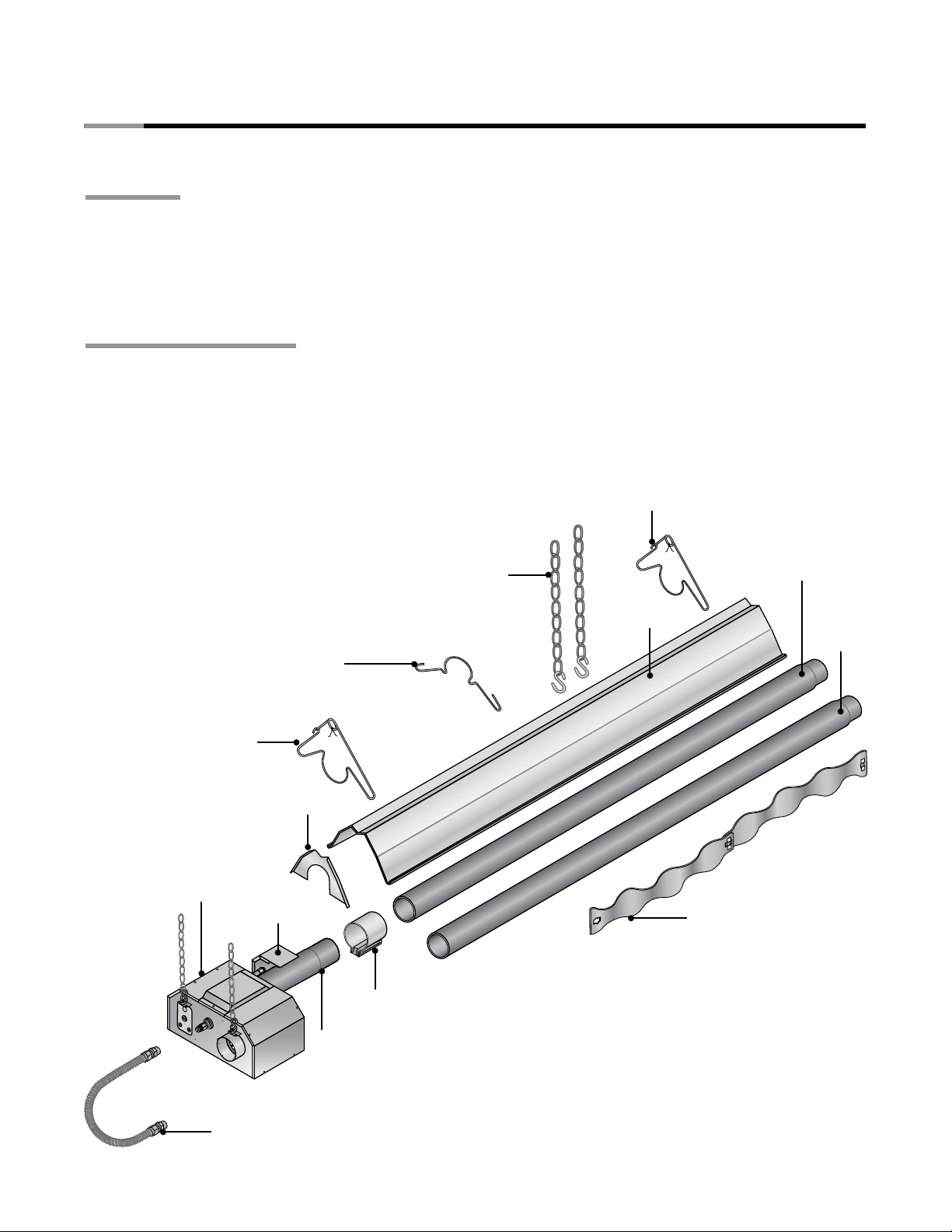
Heater Components*
Prior to installation, verify that the heater’s gas type and voltage (as listed on the rating plate) match that of
your application. Also verify that you have received all heater contents included with your tube heater.
Refer to the Series Insert for a list of the kit contents for your Series heater. Materials not included in the
heater kit contents (e.g., screws, vent material, terminals, etc.) are the responsibility of the installer. Notify
your product representative or Detroit Radiant Products of any discrepancy or missing kit contents prior to
installing unit.
Figure 1.1 • Heater Components*
Chains are not provided in kit.
Optional accessory. P/N: THCS
Reflector Center Support
Tube Hanger
Reflector End Cap with Clips*
Burner Control Box
Igniter/
Sensor Box
Tube Hanger
Reflector
10 ft. Primary/
Secondary
Combustion
Chamber(s)
Radiant
Tube(s)
Baffles
16 in. Burner Tube
SS Flex Connector*
Tube Clamp
* Not all items illustrated may be provided with your heater.
Refer to kit contents of the Series Insert Manual.
3
Page 4
!
!
!
!
2.0 Safety • Warning Symbols • Applications
2.0 Safety
WARNING
Improper installation, adjustment, alteration, service or maintenance can cause
property damage, serious injury or death. Read and understand, the installation,
operating and maintenance instructions thoroughly before installing or servicing this
equipment. Only trained, qualified gas installation and service personnel may install or
service this equipment.
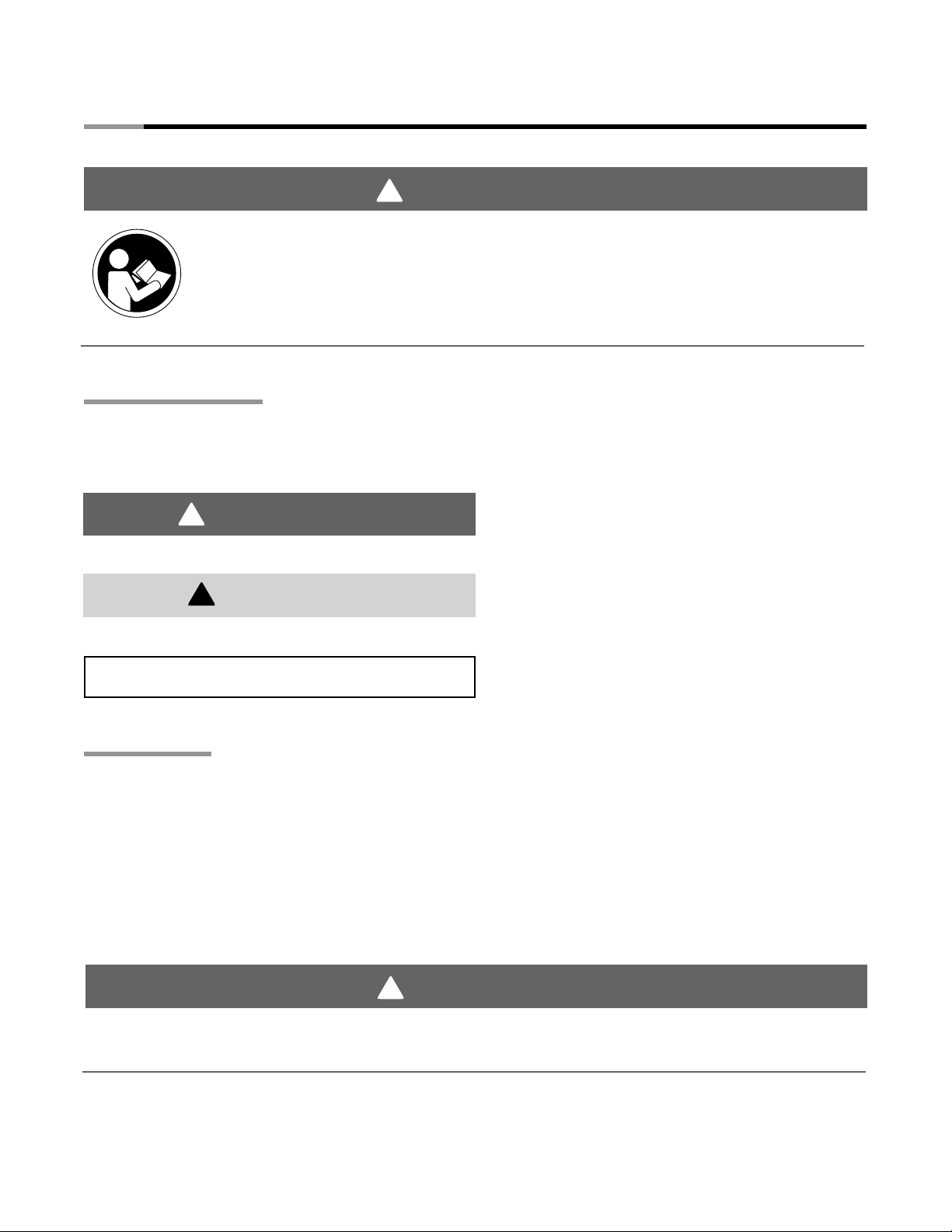
Warning Symbols
Safety is the most important consideration during installation, operation and maintenance of the tube
heater. You will see the following symbols and signal words when there is a hazard related to safety or
property damage.
Warning indicates a potentially hazardous situation
WARNING
CAUTION
NOTICE
which, if not avoided, could result in death or injury.
Caution indicates a potentially hazardous situation
which, if not avoided, could result in minor or
moderate injury.
Notice indicates a potentially hazardous situation
which, if not avoided, could result in property
damage.
Applications
This is not an explosion proof heater. No tube heater may be used in a Class 1 or Class 2 Explosive
Environment. Consult your local fire Marshall, insurance carrier and other authorities for approval if the
proposed installation is in question.
Commercial / Industrial
Unless otherwise indicated, tube heaters are designed and certified for use in industrial and commercial
buildings, such as warehouses, manufacturing plants, aircraft hangars and vehicle maintenance shops.
For maximum safety the building must be evaluated for potential problems before installing the heating
system. A critical safety factor to consider before installation is the clearance to combustibles.
WARNING
Not For Residential Use. Installation of a commercial tube heater system in residential indoor spaces
may result in property damage, serious injury or death.
4
Page 5
!
2.0 Safety • Clearance to Combustibles • Safety Signs and Labels
Clearance to Combustibles
WARNING
Placement of explosive objects, flammable objects, liquids and vapors
close to the heater may result in explosion, fire, property damage, serious
injury or death. Do not store or use explosive objects, liquids and vapor in
the vicinity the heater.
Hazards:
For maximum safety the building must be evaluated for hazards before installing the heating system.
Examples include, but are not limited to:
• Gas and electrical lines
• Combustible and explosive materials
• Chemical storage areas
• Areas of high chemical fume concentrations
• Provisions for accessibility to the heater
• Adequate clearances around air openings
• Combustion and ventilating air supply
A critical safety factor to consider before installation is the clearances to combustibles. Clearance to
combustibles is defined as
and the combustible item
The following is a partial list of items to maintain clearances from:
the minimum distance you must have between the tube surface, or reflector,
. Considerations must also be made for moving objects around the tube heater.
• Vehicle parking areas
• Vehicles with lifts or cranes
• Storage areas with stacked materials
• Lights
• Sprinkler heads
• Overhead doors and tracks
• Dirty, contaminated environment
Combustible items: Moving Objects:
• Wood • Overhead doors
• Paper • Vehicle lifts
• Fabric • Cranes
• Chemicals • Hoists
When installing the tube heating system, the minimum clearances to combustibles for your Series tube
heater and system configuration must be maintained. These distances are shown in your Series Insert
Manual and on the burner control box. If you are unsure of the potential hazards, consult your local fire
Marshall, fire insurance carrier or other qualified authorities on the installation of gas fired tube heaters for
approval of the proposed installation.
• Paint
• Parked vehicles
• Gasoline
• Storage racks
Safety Signs and Labels
It is important to provide warnings to alert individuals to potential hazards and safety actions. ANSI
Z83.20b and CSA 2.34 require you to post a sign “specifying the maximum permissible stacking height to
maintain the required clearances from the heater to the combustibles” near the heaters thermostat or in
absence of such thermostats in a conspicuous location. Contact Detroit Radiant Products Co. or an
authorized dealer for Clearance Safety Limit Signs or for Clearance Safety Limit Tags (one tag is provided
with each heater).
Safety warning labels must be maintained on the tube heater. Illustrations of the safety labels, and their
locations, are pictured in the Series Insert Manual. In locations used for the storage of combustible
materials, signs must be posted to specify the maximum permissible stacking height to maintain the
required clearances from the heater to combustibles. Signs must either be posted adjacent to the heater
thermostats or in the absence of such thermostats in a conspicuous location.
5
Page 6
!
!
!
2.0 Safety • Venting • Gas Supply • Heater Expansion
Venting
WARNING
Insufficient ventilation may result in health problems, carbon monoxide poisoning and death.
Vent enclosed spaces and buildings according to national, state, provincial and local codes.
This tube heater must be vented in accordance with national, state, provincial and local codes and the
guidelines in the Detroit Radiant Tube Heater General (refer to pages 24 - 28) and applicable Series Insert
Manual. In the United States refer to the latest edition of the ANSI Z223.1 (NFPA 54) Standard and in
Canada refer to the latest edition of the CAN/CGA B149.1 Standard.
Gas Supply
WARNING
Improperly connected gas lines may result in serious injury and death,
explosion, poisonous fumes, toxic gases or asphyxiation. Connect gas lines
in accordance to national, state, provincial and local codes.
The gas supply to the tube heater must be connected and tested in accordance with national, state,
provincial and local codes along with the guidelines in the Tube Heater General Manual (refer to pages
31-32) and Series Insert Manual. In the United States refer to the latest edition of the ANSI Z223.1 (NFPA
54) Standard and in Canada refer to the latest edition of the CAN/CGA B149.1 Standard.
Heater Expansion
WARNING
Allowances must be made for the system to expand. Improper installation, adjustment,
alteration, service or maintenance can cause property damage, injury or death.
A flexible gas connection of approved type is required. Connectors must be installed in one
plane and without sharp bends, kinks or twists.
The tube heater expands and contracts during operation. Follow the installation instructions to ensure
allowances are made for this movement. To ensure your safety, and comply with the terms of the warranty,
all units must be installed in accordance with these instructions.
6
Page 7
2.0 Safety • Standards, Certifications and Government Regulations
Standards, Certifications and Government Regulations
Installation of this tube heater must comply with all applicable local, state and national specifications,
regulations and building codes. Contact the local building inspector and/or fire marshall for guidance.
In the absence of local codes, the installation must conform to the latest edition of:
United States: National Fuel Gas Code, ANSI Z223.1 (NFPA 54).
Canada: CAN/CGA B149.1 and .2, Canadian Electrical Code C22.1
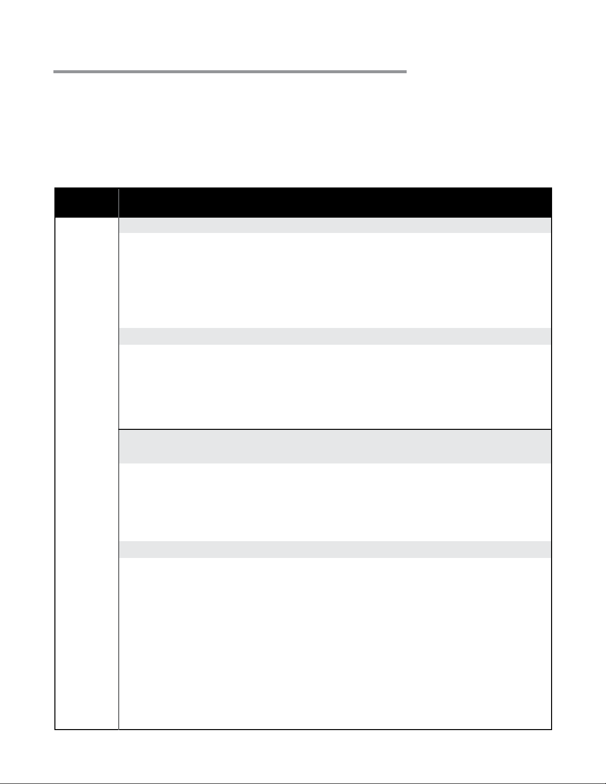
Chart 2.1 • Standards and Code Installation Guidelines • Building Type
Building
Type
Public
Garages
Aircraft
Hangars
Codes and Guidelines
Installation of this tube heater in public garages must conform to the following codes:
United States: Standard for Parking Structures NFPA 88A (latest edition) or the
Code for Motor Fuel Dispensing Facilities and Repair Garages NFPA 30A (latest
edition).
Canada: Refer to CAN/CGA B149.1: Installation Codes for Gas Burning Appliances
and applicable Standards for Public Garages.
Guidelines:
• Heaters must not be installed less than 8 ft. (2.4 m) above the floor. Minimum
clearances to combustibles must be maintained from vehicles parked below the
heater.
• When installed over hoists, minimum clearances to combustibles must be maintained
from the upper most point of objects on the hoist.
Installation of this tube heater in aircraft hangars must be in accordance with the
following codes:
United States: Refer to Standard for Aircraft Hangars, ANSI/NFPA 409
(latest edition).
In Canada: Refer to Standard CAN/CGA B149.1 and applicable Standards for
Aircraft Hangars.
Guidelines:
• In aircraft storage and servicing areas, heaters shall be installed at least 10 ft. (3 m)
from above the upper surface of wings or of the engine enclosures of the highest
aircraft that may be housed in the hangar. The measurement shall be made from the
wing or engine enclosure, whichever is higher from the floor, to the bottom of the
heater.
• In areas adjoining the aircraft storage area (e.g., shops, offices) the bottom of heaters
shall be installed no less than 8 ft. (2.4 m) above the floor.
• Suspended or elevated heaters shall be located in spaces where they shall not be
subject to damage by aircraft, cranes, movable scaffolding or other objects.
Provisions shall be made to assure accessibility to suspended tube heaters for recurrent
maintenance purposes.
7
Page 8
2.0 Safety • Standards, Certifications and Government Regulations
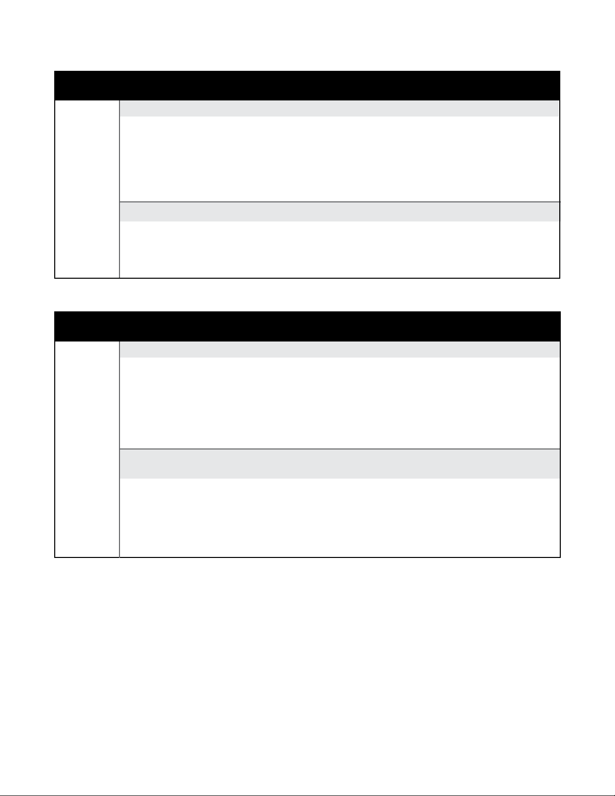
Chart 2.2 • Standards and Code Installation Guidelines • Building Location
Building
Guidelines
Location
High
Altitude
Guidelines:
Installation of this tube heater is approved, without modifications, for elevations up to
6,000 feet (1,829 m) MSL (sea level) in the United States. Contact the factory for
installations above these elevations.
The type of gas appearing on the nameplate must be the type of gas used. Installation
must comply with national and local codes and requirements of the local gas company.
Non-
Standard
BTU Gas
Guidelines:
Unless otherwise noted on the rating plate, this infrared heater is designed and orificed to
operate on standard BTU gas. Contact the factory if utilizing non-standard BTU gas.
Chart 2.3 • Standards and Code Installation Guidelines • Building Aspect
Building
Aspect
Electrical
The tube heater must be electrically grounded in accordance with the following codes:
Codes and Guidelines
®
United States: Refer to National Electrical Code
, ANSI/NFPA 70 (latest edition).
Wiring must conform to the latest edition of National Electrical
®
Code
, local ordinances, and any special diagrams furnished.
Canada: Refer to Canadian Electrical Code CSA C22.1 Part 1 (latest edition).
Venting
Venting must be installed in accordance with the requirements within this manual and the
following codes:
United States: Refer to NFPA 54/ANSI Z223.1 (latest edition), National Fuel
Gas Code.
Canada: Refer to CAN/CGA B149.1 Installation Codes for Gas Burning
Appliances.
Applicable authorities governing the manufacturing or installation of this infrared heater include
(but are not limited to) the following organizations:
• NFPA - National Fire Protection Association.
• ANSI Z83.20b - American National Standards Institute.
• NFPA 54/ANSI Z223.1 - National Fuel Gas Code.
• CSA - Canadian Standards Association.
• IAS - International Approval Services.
• AGA - American Gas Association.
• CE - Certification of Europe.
• IRSC- Infrared Heater Safety Council.
• OSHA - Occupational Safety & Health Administration.
NOTE: Refer to the Series Insert Manual for model specific certifications and approvals.
8
Page 9
!
3.0 Installation • Design Considerations and Prechecks
!
3.0 Installation
WARNING
Improper installation, adjustment, alteration, service or maintenance can cause
property damage, serious injury or death.
Read and understand, the installation, operating and maintenance instructions
thoroughly before installing or servicing this equipment.
Only trained, qualified gas installation and service personnel may install or service
this equipment.
Design Considerations and Prechecks
Placement of infrared heaters is influenced by many factors. Aside from safety factors, considerations
such as the number of heater or vent elbows that are allowed, maximum vent lengths, ducting of
combustion air and combining exhaust vents are a few examples.
To ensure a properly designed heating system, a layout should be developed for the correct placement of
the burner control box, tubes, vents and combustion air intake ducts. Inspect and evaluate the mounting
conditions, vent locations, gas supply and wiring.
When designing an infrared radiant heating system, consider the following:
• Has the building’s heat loss been evaluated?
• Does the design meet the needs of the space?
• Have recommended mounting heights been observed?
• Have all clearance to combustibles situations been observed?
• Is the supply (burner) end of the heater located where more heat is required?
• Is it best to offset the heaters and/or rotate the reflectors towards the heat zone?
• Are extra guards, side shields, ‘U’ or ‘L’ reflector covers required?
• Does the heater require outside fresh air for combustion?
• Is the environment harsh or contaminated (requiring outside air for combustion)?
• Are wind barriers required? The effective infrared surface temperature of a person or object may be
diminished with wind/drafts above 5 mph.
• Are chemicals or vapors a concern (requiring outside air for combustion or additional ventilation)?
IMPORTANT: Fire sprinkler heads must be located at an appropriate distance from the heater to avoid an
inadvertent discharge. This distance may exceed the published clearance to combustibles. Certain
applications may require the use of high temperature sprinkler heads or the relocation of the heaters.
CAUTION
Fire sprinkler systems containing propylene glycol, antifreeze or other potentially flammable substances
shall not to be used in conjunction with this heater without careful consideration for and avoidance of
inadvertent discharge hazards. For further information consult NFPA 13. Always observe applicable state
and local codes.
9
Page 10
3.0 Installation • Design Considerations
When heated, materials high in hydrocarbons (solvents, paint thinner, mineral spirits, formaldehydes, etc.)
can evaporate. This may result in odors or fumes being emitted into the environment. To correct this
problem, clean the area and/or introduce additional ventilation. The heaters themselves, when installed
and serviced in accordance with the installation manual, do not emit foul odors into the environment.
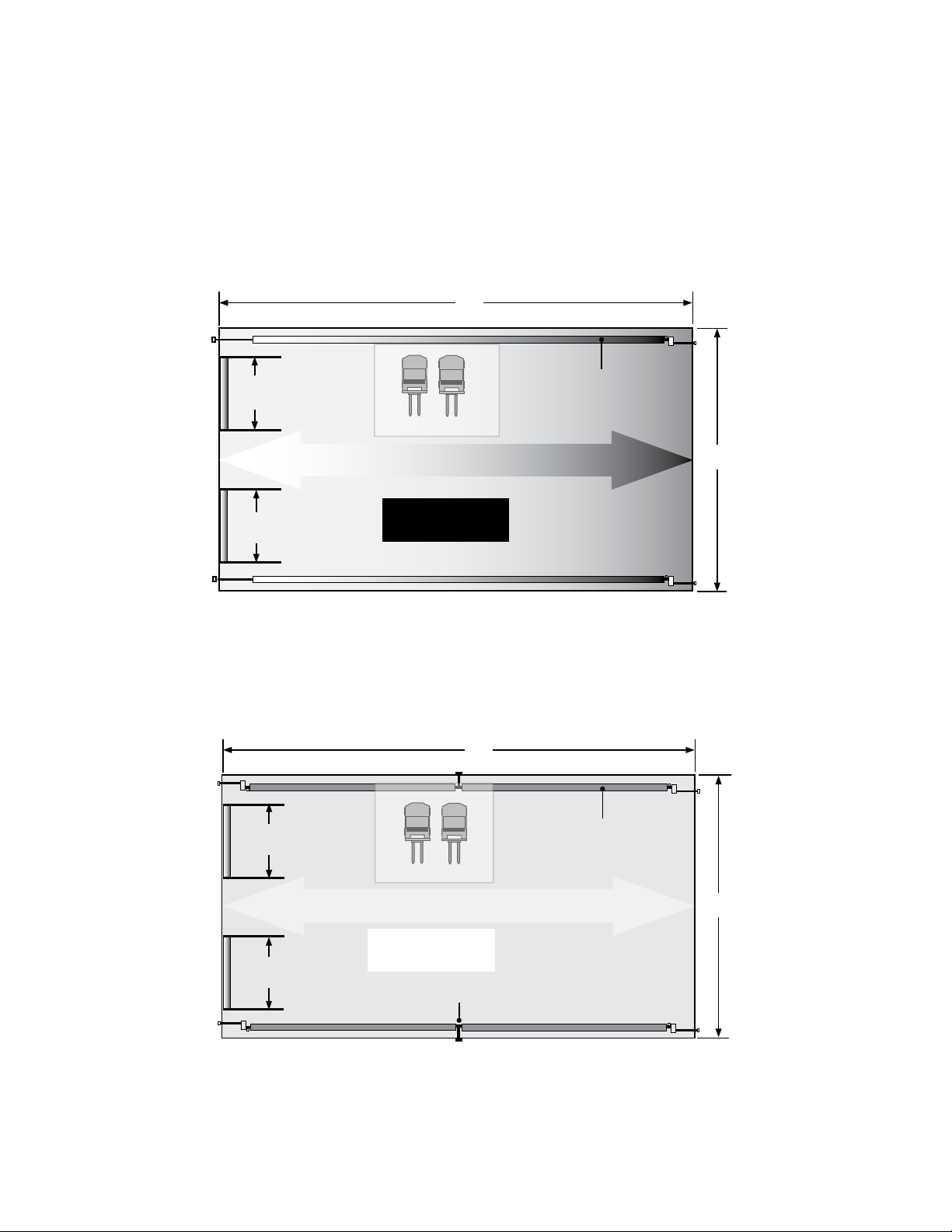
Design Scenario:
A tube heater system is being installed in a 90’ (L) x 50’ (W) x 14’ (H) space. Two overhead doors are
located at one end and an equipment storage area on one side. The calculated heat load is 400,000 BTU/h.
Figure 3.1 • Poor Design
90’
Gas Supply
Doors and
tracks
Too Cold
Doors and
tracks
Equipment storage
Poor Design
80’ - 200,000 BTU
(2 total)
Too Hot
50’
• Two burners (200,000 BTU each) are placed at one end, opposite the area of highest demand (e.g.,
overhead doors).
• Recommended mounting heights are not observed (see Chart 3.1).
• Produces an uneven heat distribution.
Figure 3.2 • Good Design
90’
Gas Supply
Doors and
tracks
Equipment storage
Better Heat Distribution
40’ - 100,000 BTU
(4 total)
50’
Good Design
Doors and
tracks
Sidewall Vent (2 total)
• Four burners (100,000 BTU each) are placed in each corner. Burner (hotter) ends direct heat to areas of
highest heat demand.
• Recommended mounting heights have been observed.
• Distributes heat more evenly.
10
Page 11
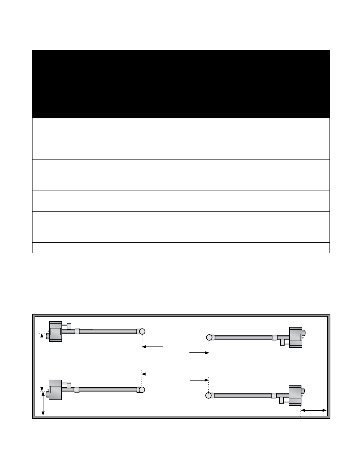
3.0 Installation • Recommended Mounting Heights and Coverages
Chart 3.1 • Recommended Mounting Heights and Coverages
NOTE: This chart is provided as a guideline. Actual conditions may dictate variation for this data.
Model
BTU Range
Recommended
Mounting Height
(ft.)
Coverage Area
Straight Config.
(LxW)
Coverage Area
U-Tube Config.
(LxW)
Distance Between
Heaters (ft.)
Dimension A
Distance Between
Heater Rows (ft.)
Dimension B
Maximum Distance
Between Heaters
and Wall (ft.)
Dimension C
20 ft. 50-65 MBH 10’ - 16’ 20’ x 12’ 12’ x 12’ 10’ - 20’ 20’ - 40’ 16’
75 -10 0 MBH 12’ - 20’ 22’ x 15’ N/A 20’ - 30’ 30’ - 50’ 18’
30 ft. 50-65 MBH 10’ - 16’ 30’ x 14’ 17’ x 13’ 10’ - 20’ 20’ - 40’ 17’
75 -125 MBH 12’ - 20’ 33’ x 18’ 18’ x 15’ 20’ - 30’ 30’ - 50’ 20’
40 ft. 50-65 MBH 10’ - 16’ 40’ x 16’ 22’ x 14’ 10’ - 20’ 20’ - 40’ 20’
75 -125 MBH 12’ - 20’ 44’ x 21’ 23’ x 17’ 20’ - 30’ 30’ - 50’ 20’
150-175 MBH 16’ - 30’ 45’ x 26’ 24’ x 20’ 30’ - 40’ 40’ - 60’ 25’
50 ft. 100 -125 MBH 15’ - 25’ 55’ x 24’ 28’ x 19’ 20’ - 30’ 30’ - 50’ 25’
150-200 MBH 16’ - 30’ 56’ x 30’ 29’ x 23’ 30’ - 40’ 40’ - 60’ 25’
60 ft. 125 MBH 16’ - 25’ 66’ x 27’ 33’ x 21’ 20’ - 30’ 30’ - 50’ 25’
150-200 MBH 17’ - 40’ 67’ x 34’ 34’ x 26’ 30’ - 40’ 40’ - 60’ 25’
70 ft. 175 - 20 0 MBH 17’ - 40’ 78’ x 38’ 39’ x 29’ 30’ - 40’ 40’ - 60’ 30’
80 ft. 200 MBH 18’ - 45’ 89’ x 42’ 44’ x 32’ 30’ - 40’ 40’ - 60’ 30’
Factory recommended mounting heights are listed as a guideline. If infrared heaters are mounted to low
or to high, they may result in discomfort or lack of heat. Detroit Radiant Products Company generally
recommends observing the recommended mounting heights to optimize comfort conditions. However,
certain applications such as spot heating, freeze protection, outdoor patio heating or very high ceilings
may result in the heaters being mounted outside of the factory recommended mounting heights.
Figure 3.3 • Mounting Height Dimensions (see Chart 3.1 for measurements)
Dim. A
Dim. B
Dim. A
Dim. C
Dim. C
Note: Dimensions A, B & C are based upon heaters hung at the factory recommended mounting height.
11
Page 12
!
3.0 Installation • Hanger Placement and Suspension
Hanger Placement and Suspension
WARNING
Improper suspension of the tube heater may result in collapse and being crushed. Always
suspend from a permanent part of the building structure that can evenly support the total
force and weight of the heater.
Failure to maintain minimum clearance to combustibles may result in fire and/or explosion,
property damage, serious injury or death. Always maintain minimum clearances and post
Clearance Safety Limit (P/N: PLQ) where needed.
Suspension of the heater must conform to applicable codes referenced in the Safety section and
these instructions.
1
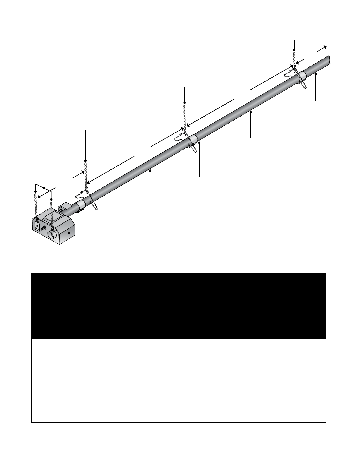
Lay all radiant tubing out in the following order. Position tubes in approximate location (see Figure 3.4).
• 10 ft. primary combustion chamber.
• If applicable, a secondary 10 ft. aluminized treated combustion chamber (150-200 MBH models
only). Refer to the Specifications Chart in the Series Insert Manual to determine if a second
combustion chamber is required for your model heater.
• Radiant emitter tubes.
Important! 150,000-200,000 BTU/h models must use the 10 ft. titanium alloy treated combustion
chamber as the first tube downstream of the burner control box. The combustion chamber has
an orange identification sticker located on the swaged end of the tube.
Stainless Steel Heaters must use the 409 Series stainless steel combustion chamber as the
first tube downstream of the burner control box.
2
Mark locations for hanging points.
NOTE: If the available hanging points do not allow for the recommended spacing then additional
hangers (P/N: TP-19B) may be necessary.
• The spacing between the burner control box mounting brackets and the first hanger should be
approximately 2’-4”.
• The space between the first two hangers placed on the first tube, should be approximately 8’-10”.
• The space between hangers thereafter, one per tube, should be approximately 9’-8”.
12
Page 13
3.0 Installation • Hanger Placement and Suspension
Figure 3.4 • Heater Mounting Layout
NOTE: A sticker identifying the combustion chamber(s)
is located on the swaged end of the tube(s).
(For 150,000-200,000 BTU/h models and all heaters
with 409 stainless steel tubes only)
Suspension
Point
Suspension
Point
Burner Control Box
Suspension Points
2’-4”
8’-10 ”
Stainless Steel Tube Clamp
(150-200 MBH models only)
Suspension Point
9’-8”
9’-8”
Radiant Emitter
Tube ( s )
Radiant Emitter Tube
NOTE: If applicable use a Secondary
Combustion Chamber. Refer to the
Specifications Chart in the Series
Insert Manual.
10 ft. Primary Combustion Chamber
NOTE: Type varies depending on
model, refer to the Specification
Chart in the Series Insert Manual.
16 in. Burner Tube
Burner Control Box
Chart 3.2 • Heater Mounting Requirements and Weights
Model
20 ft. 21’-9” / 261” 3 2 120 lbs. 145 lbs. 5 6 3 2
30 ft. 31’-5” / 377” 4 2 160 lbs. 195 lbs. 6 8 4 3**
40 ft. 41’-1” / 493” 5 2 190 lbs. 235 lbs. 7 8 5 3
Dimension*
Straight Configuration
Suspension Points
Control Box Stabilizer
Shipping Weight
Stainless Steel Ship
Weight
Chain Set Qty.
Straight
Chain Set Qty.
w/TF1B
Optional Brass
Knuckle (P/N:BK)
Optional Single
Mount Bracket
(P/N: SMB)
U configurations only
50 ft. 50’-9” / 609” 6 2 235 lbs. 290 lbs. 8 10 6 4**
60 ft. 60’-5” / 725” 7 2 265 lbs. 330 lbs. 9 10 7 4
70 ft. 70’-1” / 841” 8 2 300 lbs. 375 lbs. 10 12 8 5**
80 ft. 79’-9” / 957” 9 2 330 lbs. 405 lbs. 11 12 9 5
* Refer to page 18 for U-bend configuration dimensions.
** Model requires 5EA-SUB accessory package when installing in a U-shaped configuration.
13
Page 14
3.0 Installation • Hanger Placement and Suspension
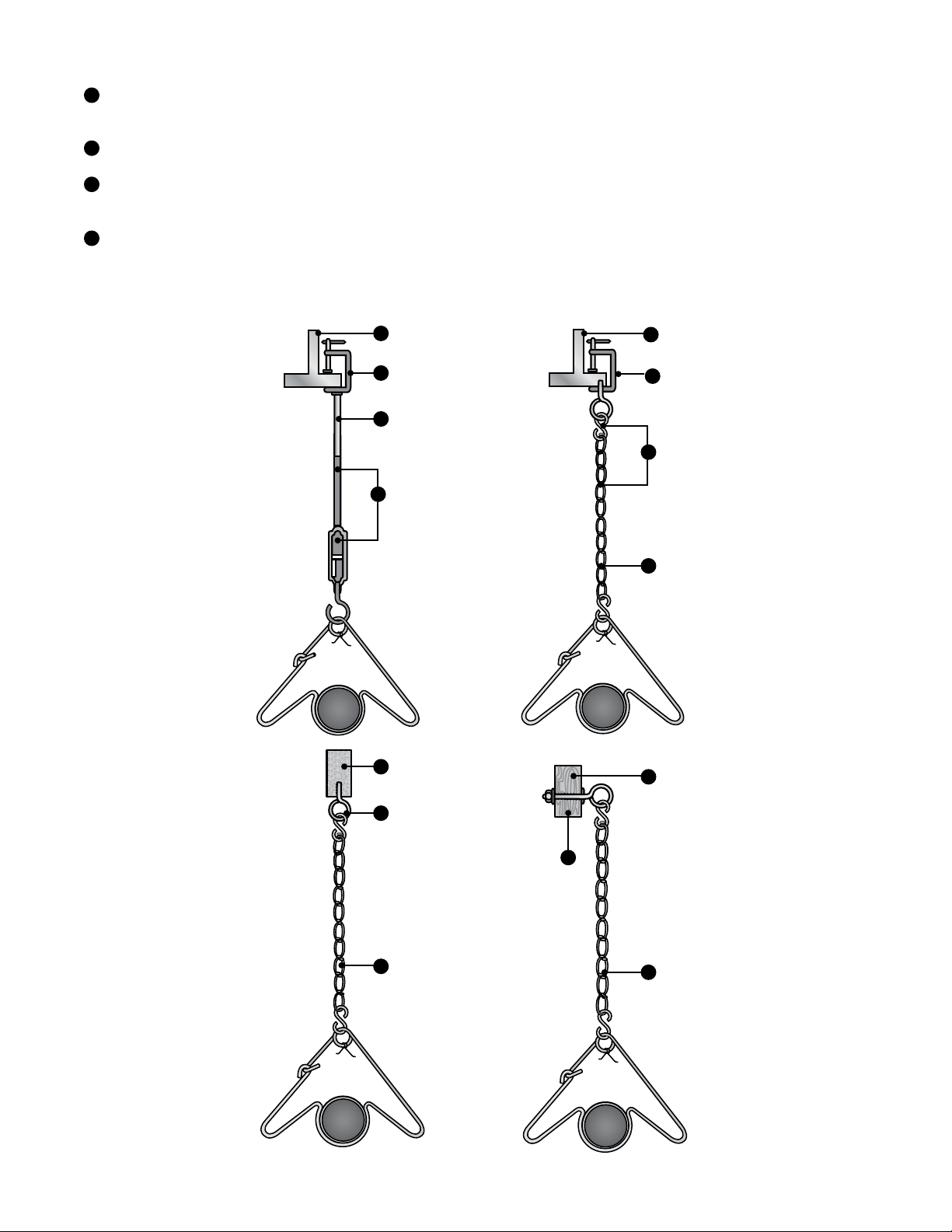
3
Prepare mounting surface, if necessary weld blocks, drill holes (see figure 3.5).
NOTE: The burner control box and radiant tubes should be in straight alignment and level.
4
Fasten beam clamp, screw hook or other type of suspension anchor to hanging point.
Attach and close S-Hook (P/N: S-HOOK) and #1 double-loop chain (P/N: THCS) to anchor. Check
5
that it is securely attached. NOTE: Threaded rod and turnbuckles may be used.
6
Attach hangers to chains. Adjust chain lengths until radiant tubing is level and equal weight distribution
is achieved. Chains must be straight up and down. Do not install chains at an angle as this can result
in tube warpage or separation.
Figure 3.5 • Mounting the Hangers
3
I-Beam
4
Beam Clamp
6
Threaded Rod
5
Threaded Rod
and Turnbuckle
I-Beam
3
Beam Clamp
4
S-Hook and
5
#1 Double-Loop Chain
3
Concrete Beam
4
Screw Hook
Chain
6
4
Screw Hook
with Locknut
and Washer
6
Chain
Wood Beam
3
6
Chain
14
Page 15
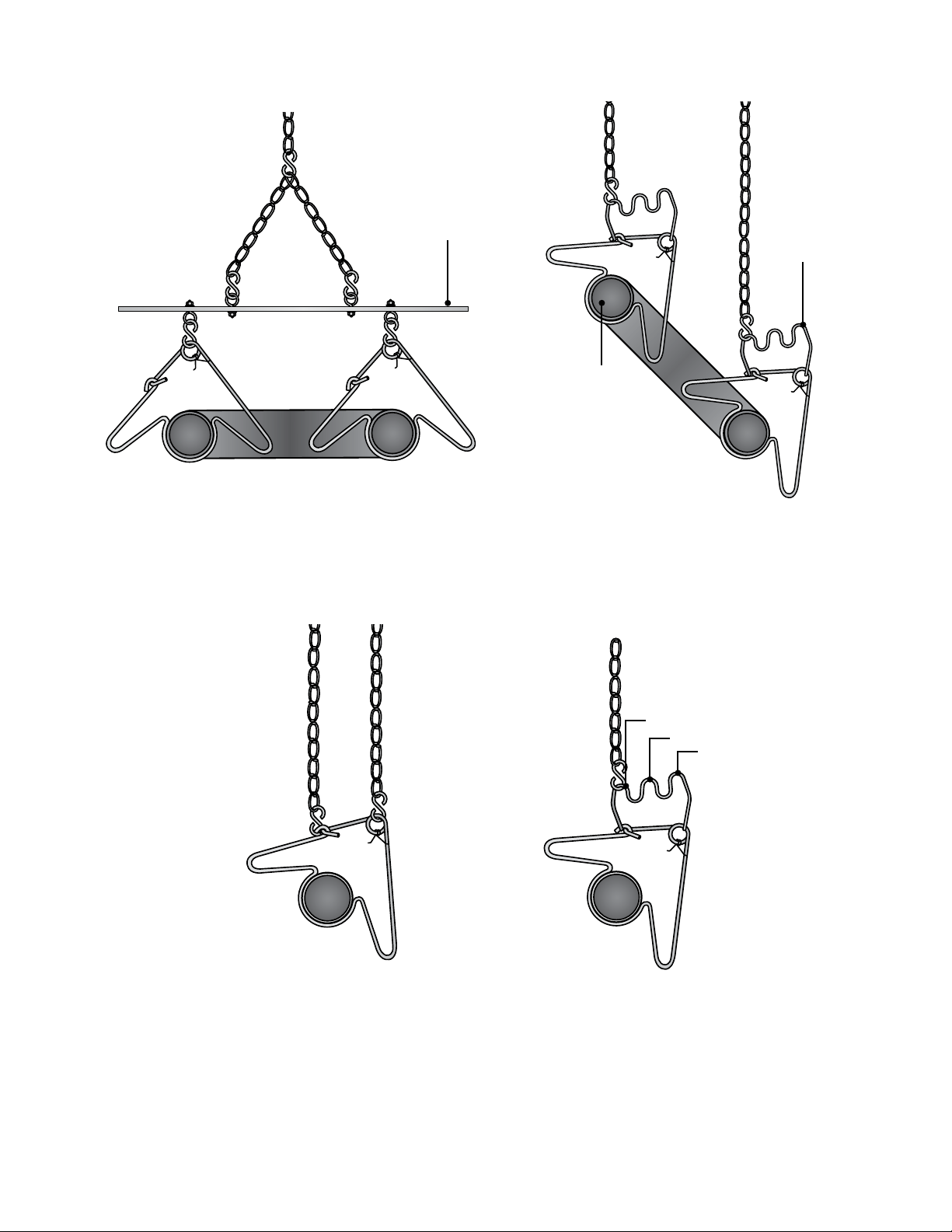
Figure 3.6 • U-Tube Hanger Mounting Options
Single Mounting
Bracket
3.0 Installation • Hanger Placement and Suspension
Brass Knuckle
Exhaust
End
U-Tubes can be mounted from a single suspension
point using a Single Mounting Bracket (P/N: SMB)
with five S-hooks and #1 double-loop chains.
Figure 3.7 • Angled Hanger Mounting Options
U-Tubes can be mounted at a
15, 30 or 45 degree angle with two
suspension points, using two Brass Knuckle
(P/N: BK) fittings, #1 double-loop chains and S-hooks.
45°
30°
15°
For 45 degree hanging angle use two
S-hooks and two #1 double-loop chains.
For variety of hanging angles, use the Brass
Knuckle (P/N: BK) fitting with a #1 doubleloop chain and S-hook.
15
Page 16
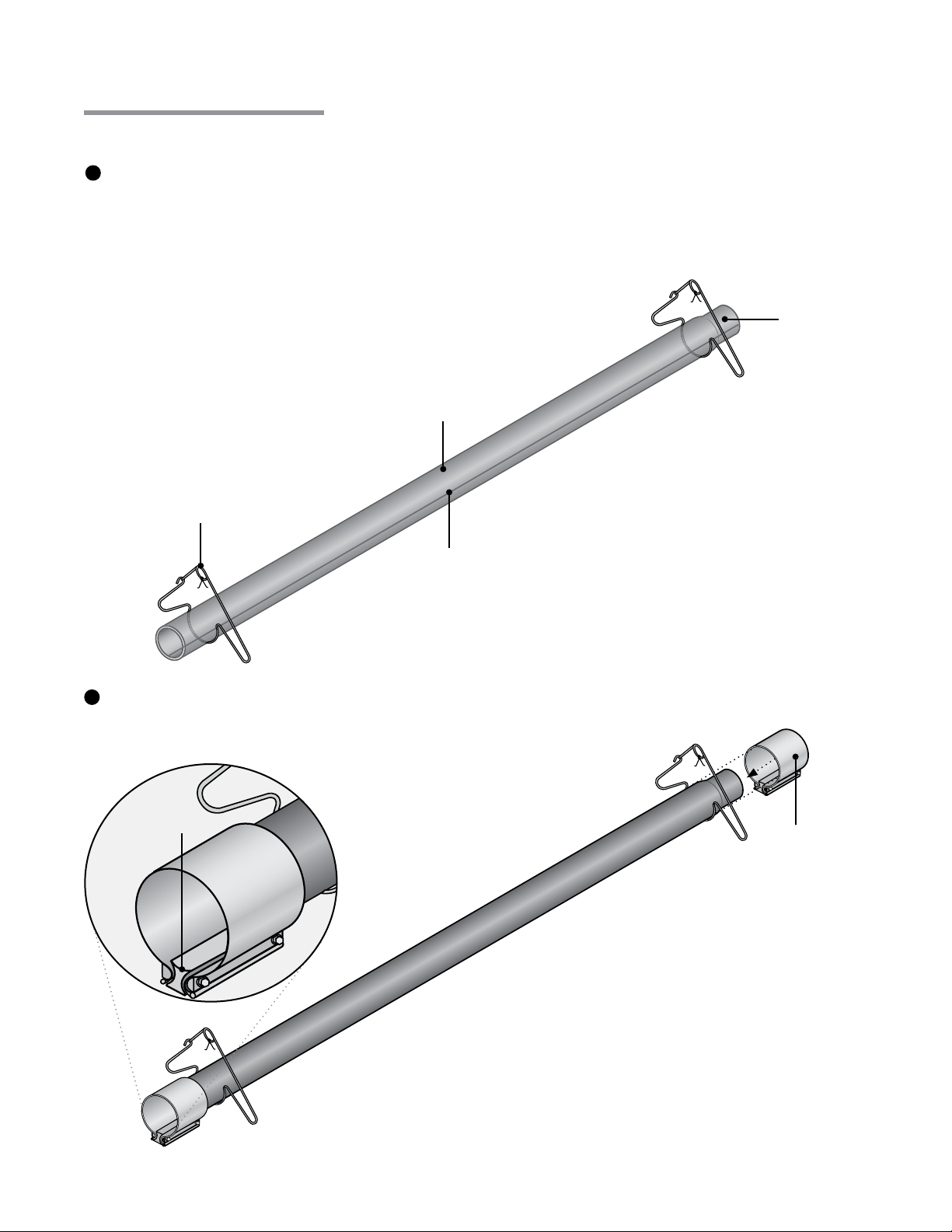
3.0 Installation • Radiant Tube Assembly
Radiant Tube Assembly
To install the radiant tubes:
1
Place tubes in hangers with the welded seam facing downward and the swaged end of the tube
towards the exhaust end of the heater system (see figure 3.8).
Refer to the Series Insert Manual for tube installation sequence. Place the combustion chamber as
the first tube connected to the burner control box. These tubes have an identification sticker on the
swaged end.
Figure 3.8 • Attach Hangers
Swaged End
Radiant Tube
Hanger
Welded Seam
Faces Down
2
Slide tube clamps onto radiant tubes (see figure 3.9).
Figure 3.9 • Attach Tube Clamps
NOTE: If the tube clamp comes
apart, the spacer must be
re-assembled with the spacer’s
Concave surface
concave surface facing against
the radiant tube surface.
Tube Clamp
IMPORTANT! 150,000 to 200,000 BTU/h models must be
installed with a stainless steel tube clamp (P/N: TP-220) located at
the seam between the primary combustion chamber and the
second tube section downstream of the burner control box.
16
Page 17
3.0 Installation • Optional Elbow or U-Bend Accessory Configuration
3
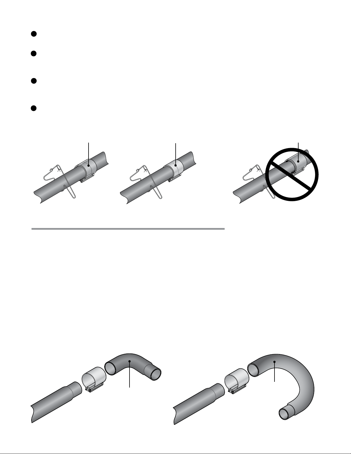
Slip-fit the radiant tube sections together until tightly connected (install the swaged end of each tube
towards exhaust end). NOTE: If it is difficult to mate the tubes, they may be installed incorrectly.
4
Center tube clamps over the seam where two radiant tube sections connect. If necessary, rotate tube
clamps so they will not interfere with the reflector end caps during expansion and contraction of
the heater.
5
Tighten tube clamp bolts to secure. When proper compression is obtained (40-60 ft-lbs. torque) the
tube seam will create a visible mark on the tube clamp. NOTE: Excessive torque may damage the
tube clamp.
6
Determine the location of the burner control box and note the placement of the mounting chains.
Figure 3.10 • Tube Connections
Tubes fit snuggly together and the
tube clamp is centered over the seam.
The tube clamp is tight when the
torque is achieved (normally
when seam becomes visible).
Tubes are not fit snuggly
together and the tube clamp is
not centered over the seam.
Correct Tube Connection Incorrect Tube Connection
Optional Elbow or U-Bend Accessory Configuration
A 90 degree elbow or 180 degree U-bend accessory fitting may be installed in the radiant tube heating
system. Refer to Chart 3.3 for minimum distance requirements from the burner control box.
When installing an Elbow or U-Bend Accessory Fitting:
• The top clearance of an uncovered (no reflector) elbow or U-bend accessory fitting to combustibles
is 18 in.
• If operating the heater unvented, separate the intake air to the heater from its exhaust products a
minimum of 4 ft., further separation may be necessary. Combustion air may also be supplied.
• A maximum of two 90° elbows or one 180° U-bend can be installed on a heater.
• Omit one 36 in. section of turbulator baffle. Refer to Baffle Assembly section.
Figure 3.11 • Optional Tube Connections
90 Degree Elbow Bend
(P/N: E6)
180 Degree
U-Bend
(P/ N : TF1B)
17
Page 18
3.0 Installation • Optional Elbow or U-Bend Accessory Configuration
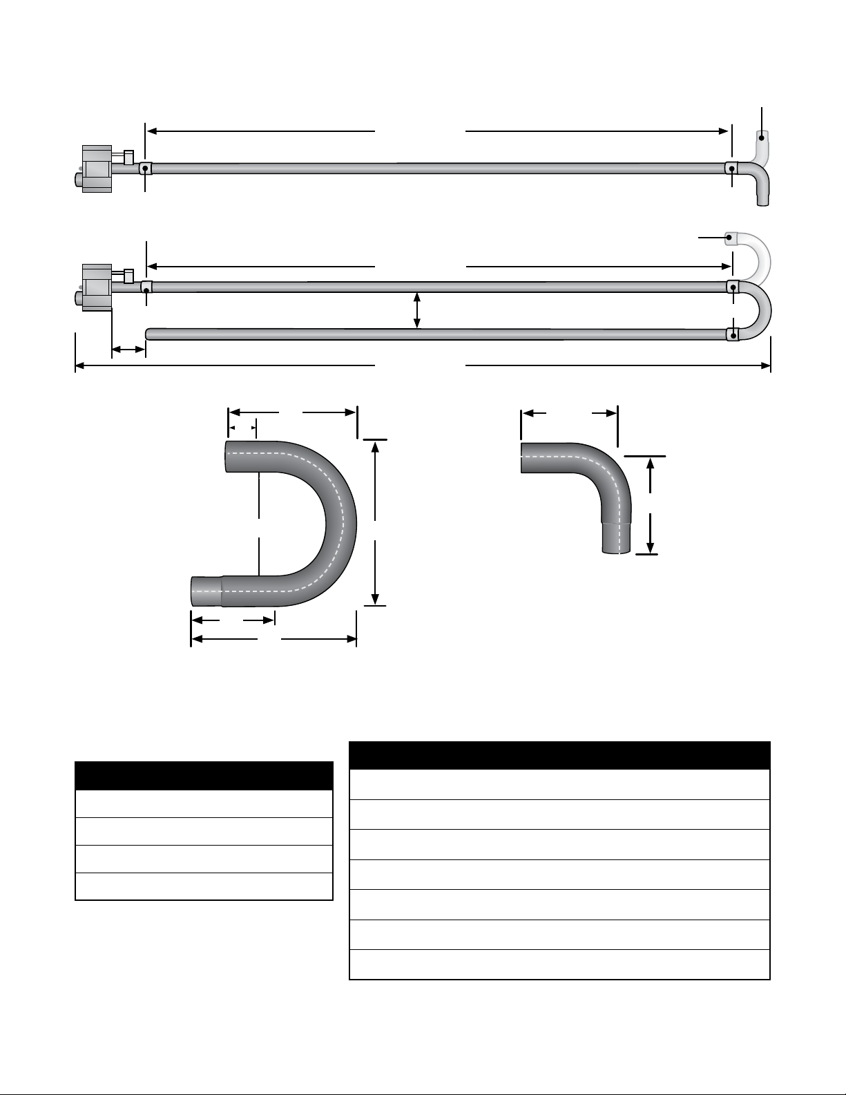
Figure 3.12 • Elbow and U-Bend Clearances
Tube Clamp
Tube Clamp
8”
Figure 3.13 • U-Bend and Elbow Dimensions
16”
6”
Dimension A
Dimension A
12”
Dimension B
Elbow can be set
in both directions
Tube Clamp
U-Bend can be set in both directions
Tube Clamp
12.5”
16”
P/N: TF1B
10”
20”
Chart 3.3
Minimum Distance From Burner
Control Box to Elbow or U-bend
Accessory Fitting
Models (MBH) Dimension A
50 - 100 10 f t.
110 - 125 15 f t.
130 - 175 20 ft.
200 25 ft.
NOTE: Maintain a 36” minimum
distance from vent to combustion air
intake on heaters fitted with a U-bend
accessory fitting.
12.5”
20”
P/N: E6
Chart 3.4
Overall Dimensions for Heaters Configured
With U-Bend (P/N: TF1B)
Model Dimension B Notes
20 ft. 13’ - 1” / 157” N/A
30 ft. 17’ - 9” / 213” Requires P/N: 5EA-SUB *
40 ft. 22’ - 9” / 273” N/A
50 ft. 27’ - 5” / 329” Requires P/N 5EA-SUB *
60 ft. 32’ - 5” / 389” N/A
70 ft. 37’ - 3” / 447” Requires P/N 5EA-SUB *
80 ft. 42’ - 1” / 505” N/A
* 5EA-SUB may only be ordered at the time of heater
production. Field corrections require two (2) TR-60 packages.
18
Page 19
3.0 Installation • Burner Control Box Suspension
Burner Control Box Suspension
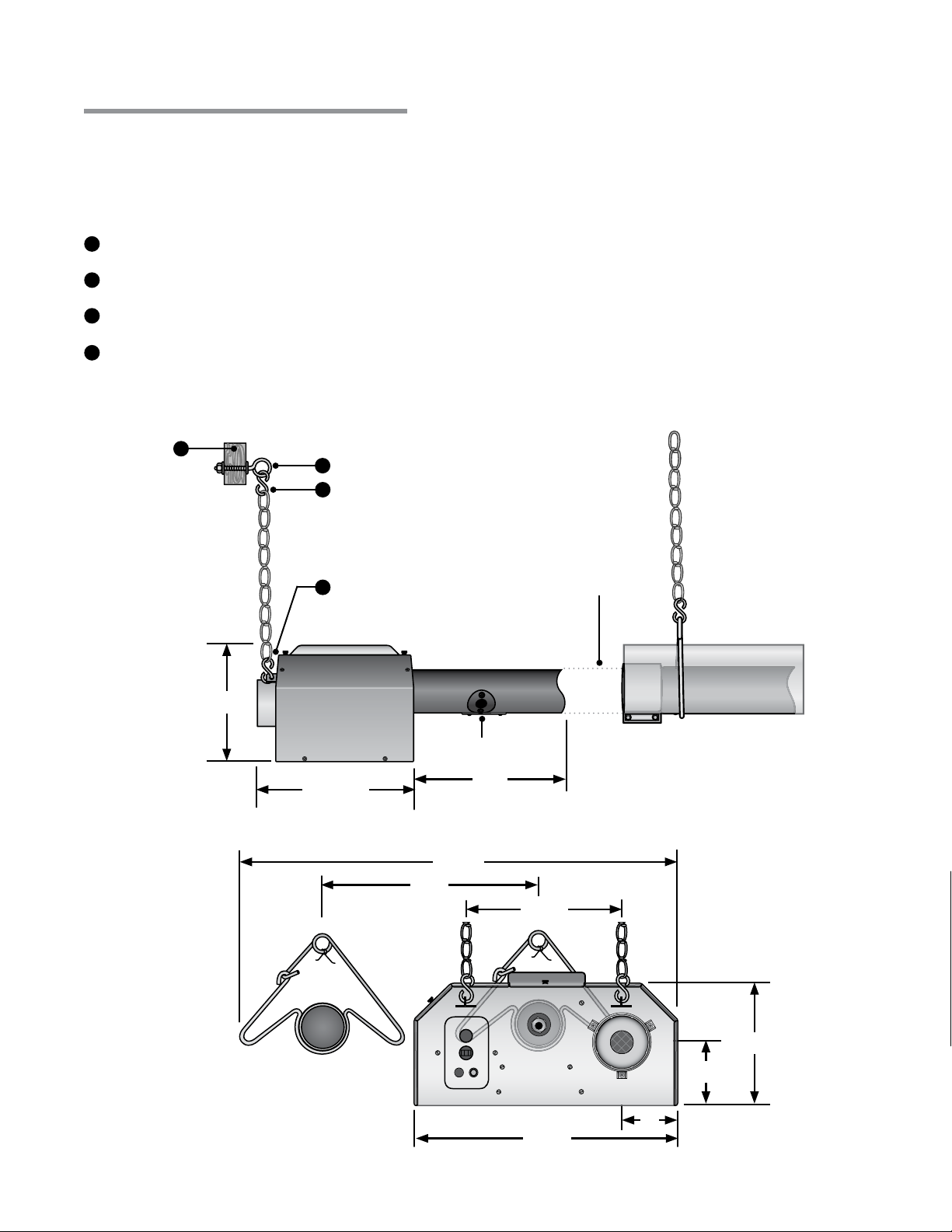
Suspending the burner control box must be done in accordance with applicable codes listed in the Safety
section and these instructions.
The burner control box must be in straight alignment with all radiant tubes and level. Contact your local
distributor or the factory to see if your application allows for the rotation of the burner control box.
1
Determine the mounting chain locations for hanging the burner control box.
2
Fasten beam clamp, screw hook or other type of suspension anchor to hanging point.
3
Attach S-hook and #1 double loop chain (P/N: THCS) to anchor. Check that it is securely connected.
4
Attach chain assemblies and S-hooks to mounting brackets on the burner control box. Adjust chain lengths
until level and in straight alignment with radiant tubes. Burner sight glass will be visible from the floor.
Figure 3.14 • Burner Control Box Assembly • Side View
1
2
3
Burner Control Box tube is in
straight alignment with 10’
4
Primary Combustion Chamber
9.625”
Burner Sight Glass
12.875”
16”
Figure 3.15 • Burner Control Box with U-Bend • End View
32.8”
16”
11. 25 ”
19
8.625”
4.5”
4”
18.5”
Page 20
3.0 Installation • Reflector Assembly
Reflector Assembly
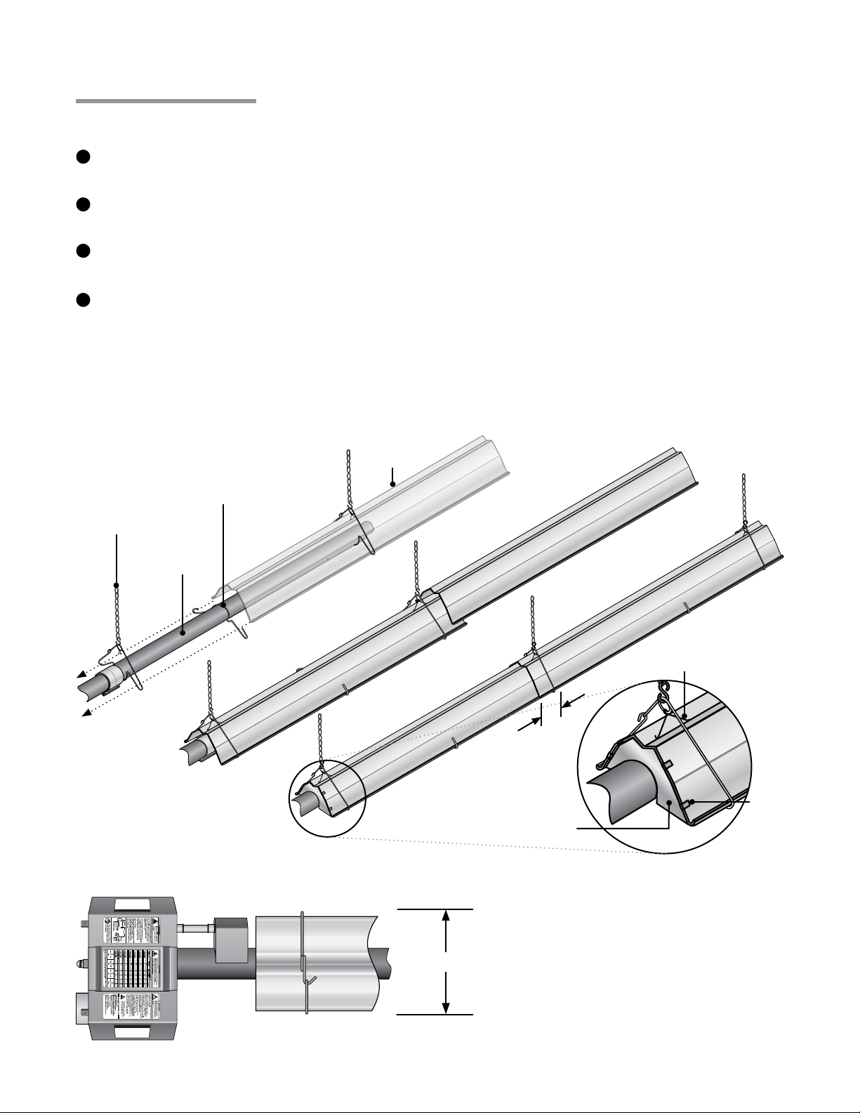
To install the reflectors (see figure 3.16):
Attach the reflector center supports onto radiant tubes. NOTE: On models equipped with a single
1
reflector center support, place at mid-point of primary combustion chamber.
Slide each reflector section through the hangers and adjust the reflector tension spring (if applicable)
2
into the V-groove on the top of the reflector. The reflectors should overlap approximately 4 inches.
3
To prevent the reflectors from shifting, secure the reflector sections together using sheet metal screws,
except at the expansion joint (see Chart 3.6). NOTE: Installer to supply sheet metal screws.
Attach reflector end caps (if applicable), with polished finish inward, to each end of the reflector run.
4
Secure with clips.
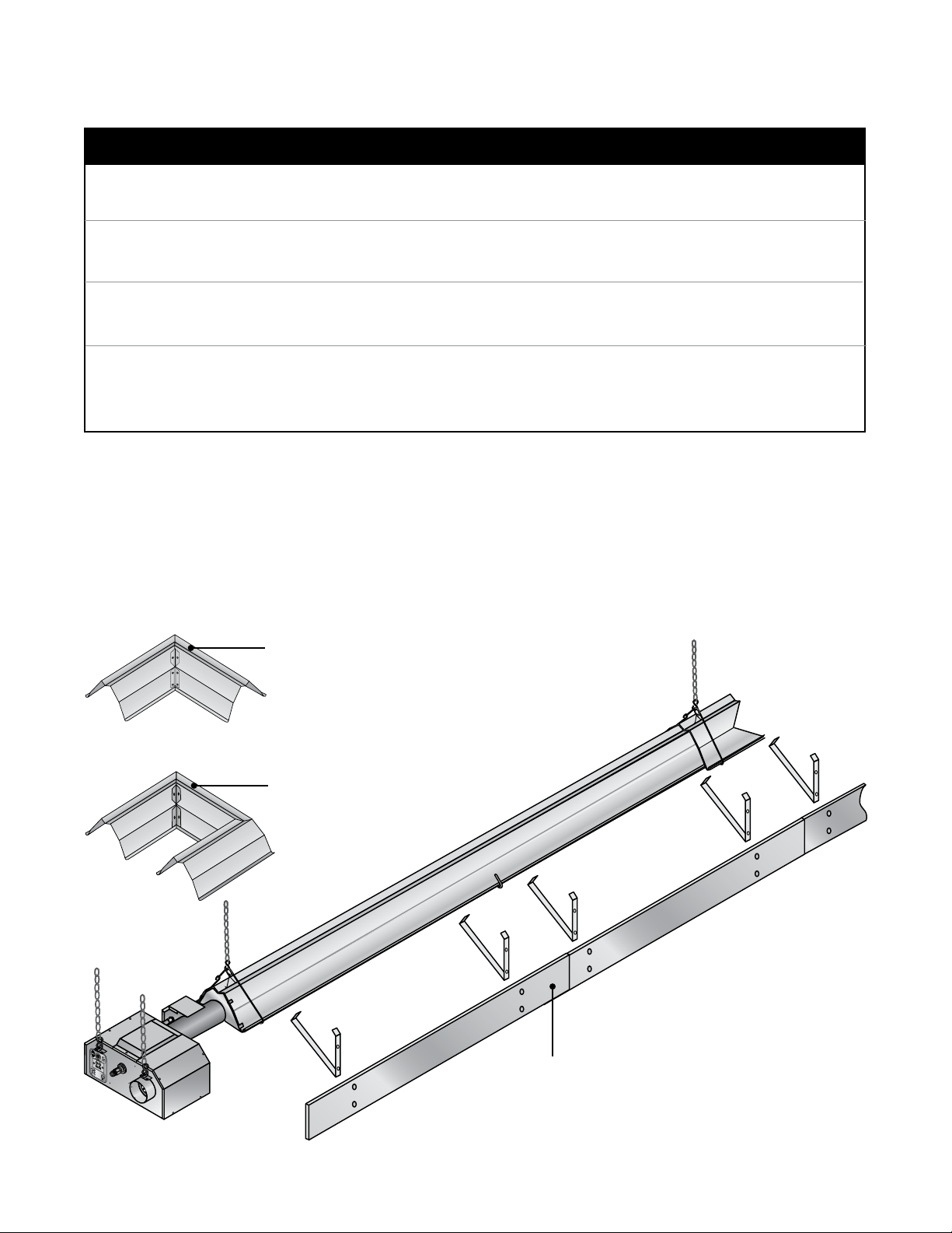
Reflectors, and reflector accessories, direct infrared energy to the floor level. The reflector assembly
depends on the heater configuration, proximity to combustibles and space surrounding the heater.
Before you begin assembly, determine if the use of reflector accessories are necessary (see Chart 3.5).
Figure 3.16 • Reflector Assembly
Hanger
and Chain
Reflector
Reflector Center
Support
Radiant
Tube
Reflector Tension
Spring
4” Overlap
Clips
Reflector End Cap
Figure 3.17 • Width of Installed Reflector - Top View
KEEP COVER IN PLACE. REMOVE FOR SERVICE ONLY.
4. Swing hinged panel downward.
3. Remove top cover.
2. Remove four (4) thumbscrews.
1. Disconnect gas & electricity.
CONTROLS & GAS VALVE COMPARTMENT
SERVICE ACCESS PANEL
13.75”
SERVICE ACCESS PANEL
FAN COMPARTMENT
1. Disconnect gas & electricity.
2. Remove top cover (2 thumbscrews).
3. Remove tsix (6) 1/4” screws.
4. Lift and remove panel.
KEEP COVER IN PLACE. REMOVE FOR SERVICE ONLY.
20
Page 21
3.0 Installation • Reflector Assembly • Common Optional Accessories
Chart 3.5
Common Optional Accessories
Reflector Accessory Description Part Number
Elbow Reflector* 90° bend, highly polished aluminum reflector elbow RE
designed to fit atop one elbow accessory fitting.
U-Reflector* 180° bend, highly polished aluminum reflector U-bend RU
designed to fit atop one U-bend accessory fitting.
Side Shield Extension** Highly polished side shield extension used to direct SSE
infrared rays downward, away from sidewalls and combustibles.
Protective Guard Used to prevent debris or objects from becoming lodged PG
between the radiant tube and reflector. Required when
mounting heaters below 8 ft.
* Reflectors cannot be rotated when used with a reflector elbow (RE), U-shaped reflector (RU), or
side shield (SSE).
** Refer to the Clearance to Combustible chart in the Series Insert Manual for minimum distances to
combustibles when side shield extension(s) are used.
Additional accessory options are listed in the Detroit Radiant Products Company Tube Heater Accessory
Guide or online at www.detroitradiant.com.
Figure 3.18 • Reflector Shield Accessories
Elbow reflector (P/N: RE)
Used over a 90-degree
elbow radiant tube.
U-shaped reflector (P/N: RU)
Used over a ‘U’ shaped
radiant tube.
21
Side shield extension (P/N: SSE)
Directs infrared rays downward, away
from sidewalls and combustibles.
Page 22
3.0 Installation • Baffle Assembly and Placement
Baffle Assembly and Placement
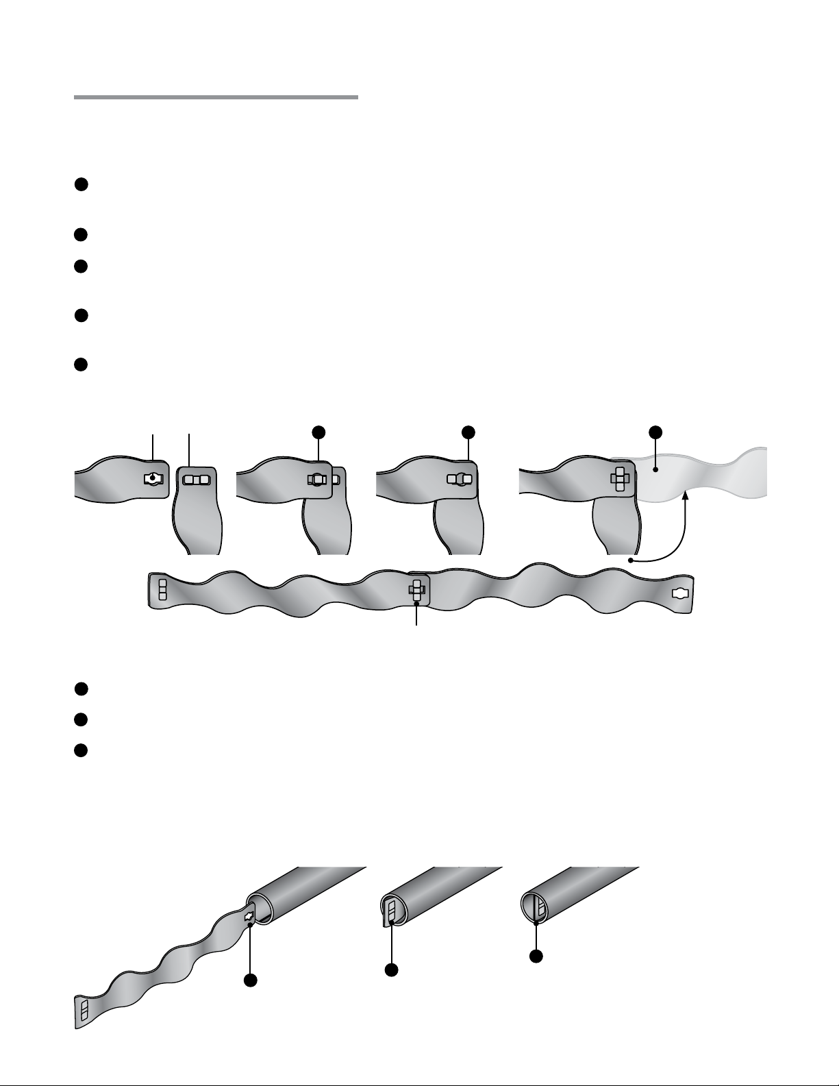
Different models and inputs utilize specific baffle lengths. Remove all enclosed baffle sections from box
and retain with applicable heater. Reference shipping label for proper baffle size.
To assemble the baffles: NOTE: Baffles may be inserted into the tube while being assembled.
1
Determine the number of baffles needed for your model number. Remove one 36 in. baffle section
if heater is fitted with an elbow (P/N: E6) or U-bend (P/N: TF1B) accessory.
Orient the baffle tabs at a 90° angle to the baffle keyhole (see figure 3.19).
2
Insert one baffle tab into keyhole and slide completely to one side until both baffle tabs appear in
3
the keyhole.
4
Adjust the tabs to the center of the keyhole and rotate the baffle 90 degrees to lock the baffle
sections together.
5
Repeat this process with all remaining baffle sections to complete assembly.
Figure 3.19 • Assembling the Baffles
Baffle keyhole
Baffle tabs
2
3 4
Completed connection
To insert the baffles:
Insert baffles with the keyhole end first.
1
2
Rotate baffle assembly so that it is in the vertical position.
3
Slide baffle assembly into the last radiant tube section, furthest from the burner control box. NOTE:
Baffle assemblies longer than 10 ft. will continue to be fed into next tube section. When the heater is
configured with a ‘U’ or ‘L’ shaped accessory fitting It may be necessary to cut the baffle in two
sections. In this case, place as much baffle as possible downstream of the fitting and the remainder
just before the fitting.
Figure 3.20 • Inserting the Baffles
3
1
2
IMPORTANT: Baffle assembly
must be flush with the end of
the last tube section and in the
vertical position.
22
Page 23
3.0 Installation • Final Heater Assembly
Final Heater Assembly
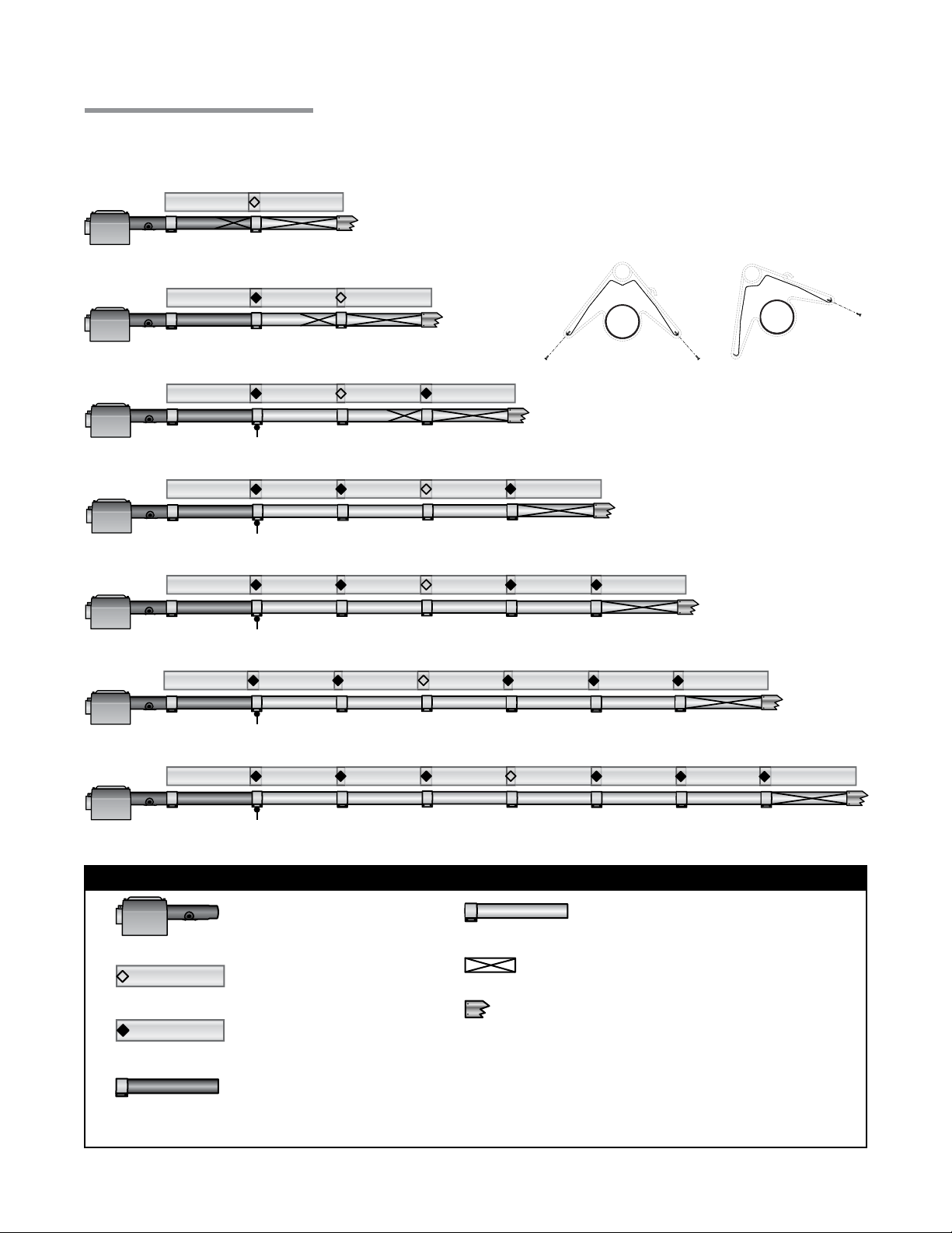
Chart 3.6
Tube Installation Sequence, Baffle Location and Secured Joints for Reflectors
NOTE: When securing joints on reflectors which
are rotated on an angle from horizontal, secure
joint only on top side of reflector to allow for
20 Foot
30 Foot
40 Foot
*
Stainless steel clamp on 150,000 to 175,000 BTU/h
models (P/N: TP-220).
sufficient heater expansion and contraction.
1 to 45° Mounting Angle0° Mounting Angle
50 Foot
60 Foot
70 Foot
80 Foot
*
Stainless steel clamp on 150,000 to 200,000 BTU/h
models (P/N: TP-220).
*
Stainless steel clamp on 150,000 to 200,000 BTU/h
models (P/N: TP-220).
*
Stainless steel clamp on 150,000 to 200,000 BTU/h
models (P/N: TP-220).
*
Stainless steel clamp on 150,000 to 200,000 BTU/h
models (P/N: TP-220).
Key
Burner Control Box
w/16 in. Burner Tube
Expansion Joint on
Reflectors
Secure vent material to exchanger with three #8
Secured Joint on
Reflectors
sheet metal screws. Seal with high temperature
silicone sealant. Do not use tube clamp.
Radiant Tube
Exchanger with Clamp
Baffle Location
Primary Combustion
Chamber with Clamp
A secondary combustion chamber is installed as the
*
second tube downstream from the burner control box on
150,000 to 200,000 BTU/h models. Refer to the Series
Insert Manual for installation requirements.
23
Page 24
!
3.0 Installation • Venting
Venting
WARNING
Insufficient ventilation and/or improperly sealed vents may release gas into the building
which could result in health problems, carbon monoxide poisoning or death.
Improper venting may result in fire, explosion, injury or death.
Seal vent pipes with high temperature sealant and three (3) #8 sheet metal screws.
Vent enclosed spaces and buildings according to the guidelines in this insert manual
and applicable national, state, provincial and local codes.
The heating system may operate either vented or unvented (see page 28). Venting can terminate through
the sidewall (horizontal) or the roof (vertical) and be individually or commonly vented.
Follow these guidelines and all applicable codes for all models, prior to installing vent material. Local
codes may vary. In the absence of local codes, refer to and comply with the National Fuel Code ANSI
Z223.1 (NFPA 54) latest edition or the National Standards of Canada.
Venting Requirements
• 4 in. single wall galvanized steel vent pipe or Dura/Connect single wall flexible exhaust vent must
be used.
• Secure vent pipe to the swaged exhaust end of tube exchanger using three (3) #8 x 3/8 sheet
metal screws (field supplied). Seal with high temperature silicone sealant (field supplied).
NOTE: Tube clamps provided in kit are not to be used for this connection.
• Seal single wall vent joints with high temperature sealant (field supplied) and three (3) #8 sheet
metal screws (field supplied).
• Single wall galvanized vent pipe must be insulated in cold environments.
• Do not use more than two 90 degree elbows in the exhaust vent.
• To maintain clearances to combustibles, the use of an approved wall or roof thimble and double-
wall Type-B vent is required for the portion of vent pipe that runs through combustible material in
the building wall or roof (see figures 3.21 & 3.22).
• Consult the NFPA ANSI Z223.1 Gas Vent Termination criteria if roof pitch exceeds 9:12.
• Maximum vent length for all models is 20ft. (6 m).
• Maintain a 36” minimum distance from vent to combustion air intake on heaters fitted with a U-bend
accessory fitting.
24
Page 25
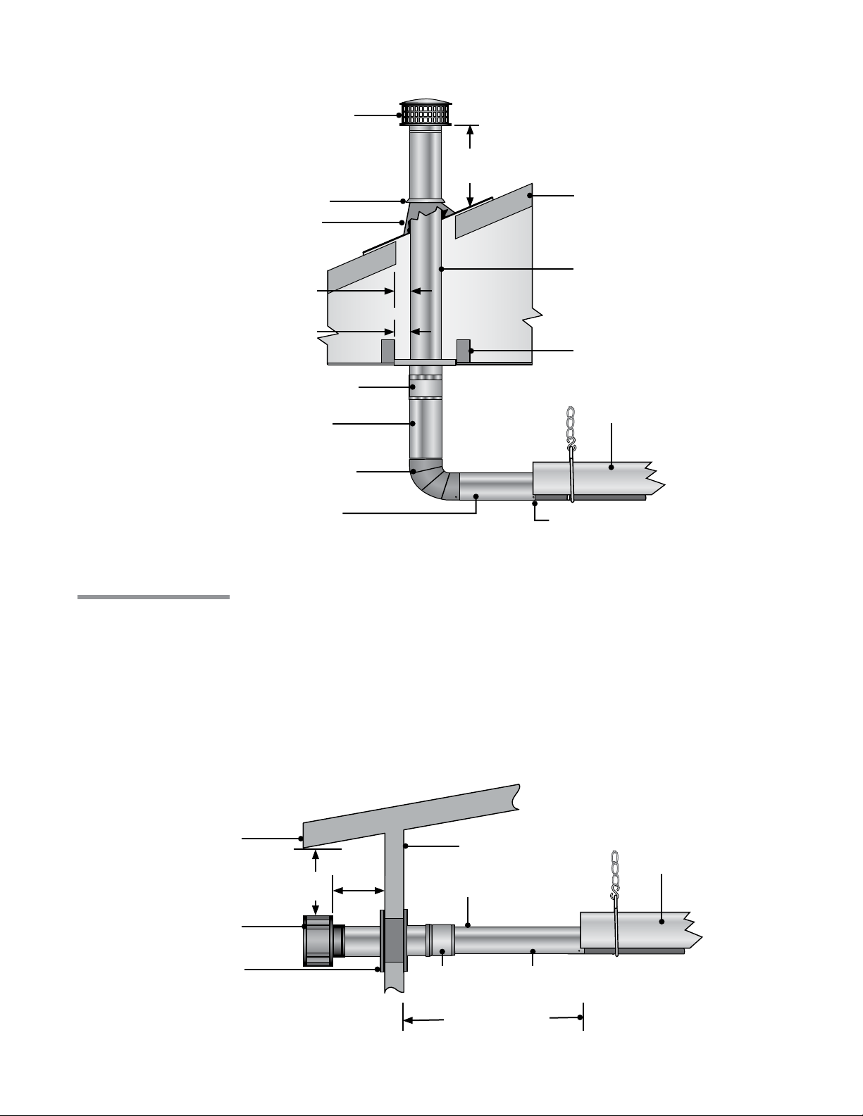
Figure 3.21 • General Vent Requirements
Vent Cap
Storm Collar
Adjustable Roof Flashing
1 in. Minimum Clearance
1 in. Minimum Clearance
B to C Adapter
3.0 Installation • Venting • Sidewall Venting
24 in.
Min.*
Roof*
Double-Wall B Vent
Fire Stop Spacer
Single-wall Vent Pipe
Single-Wall Elbow or Alternate Tee Fitting
Single-wall Vent Pipe
*Consult the NFPA ANSI Z223.1 Gas Vent Termination criteria if roof pitch exceeds 9:12
Heater
#8 Sheet Metal Screws
Sidewall Venting
Guidelines:
Vent Pipe Angle
• To prevent moisture from entering the heater system, slope the vent pipe down toward the outlet
1/4 in. per foot of length. Do not pitch the heater.
• **Vent must extend beyond any combustible overhang if the vent is less than 36 in. below the
combustible overhang.
Figure 3.22 • Sidewall Venting Requirements
Building Overhang
Sidewall Vent Cap
Wall Thimble
36 in.
min.**
6 in.
min.**
Sidewall
B to C Adapter
Double-Wall
B-Vent
1/4 in. downward
pitch per foot
25
Heater
Single
Wall Vent
Page 26
3.0 Installation • Sidewall Venting • Roof Venting
Vent Termination
United States:
• Vent must terminate a minimum of 4 ft. (1.2 m) below, 4 ft. (1.2 m) horizontally from, or 1 ft.
(30 cm) above any window or door that may be opened or gravity air inlet into the building.
• Vent must terminate a minimum of 3 ft. (.9 m) above any forced air inlet that is located within
10 ft. (3.1 m).
• The bottom of the vent terminal must be located a minimum of 12 in. (30 cm) above grade level
and must extend beyond any combustible overhang. Vents adjacent to public walkways must
terminate a minimum of 7 ft. (2.1 m) above grade level.
• The vent terminal must be installed to prevent blockage by snow and protect building materials
from degradation by flue gases.
• The vent cap must be a minimum of 6 in. (15.2 cm) from the sidewall of the building.
• Vent must be a minimum of 36 in. below or extend beyond any combustible overhang.
• Consult the NFPA ANSI Z223.1 Gas Vent Termination criteria if roof pitch exceeds 9:12.
Canada:
• Vents must terminate a minimum of 3 ft. (.9 m) from a window or door that may be opened, and
non-mechanical air supply inlet or combustion air inlet into the building.
• Vents must terminate a minimum of 6 ft. (1.8 m) from a mechanical air supply inlet.
Rooftop Venting
Guidelines:
Vent Locations and Clearances
• Separate air intake duct from vent pipe a minimum of 4 ft. (1.2 m) by placing vent pipes higher
than adjacent air intake duct.
• Venting may utilize standard B-vent cap.
• The vent terminal must extend a minimum of 2 ft. (.6 m) above the roof.
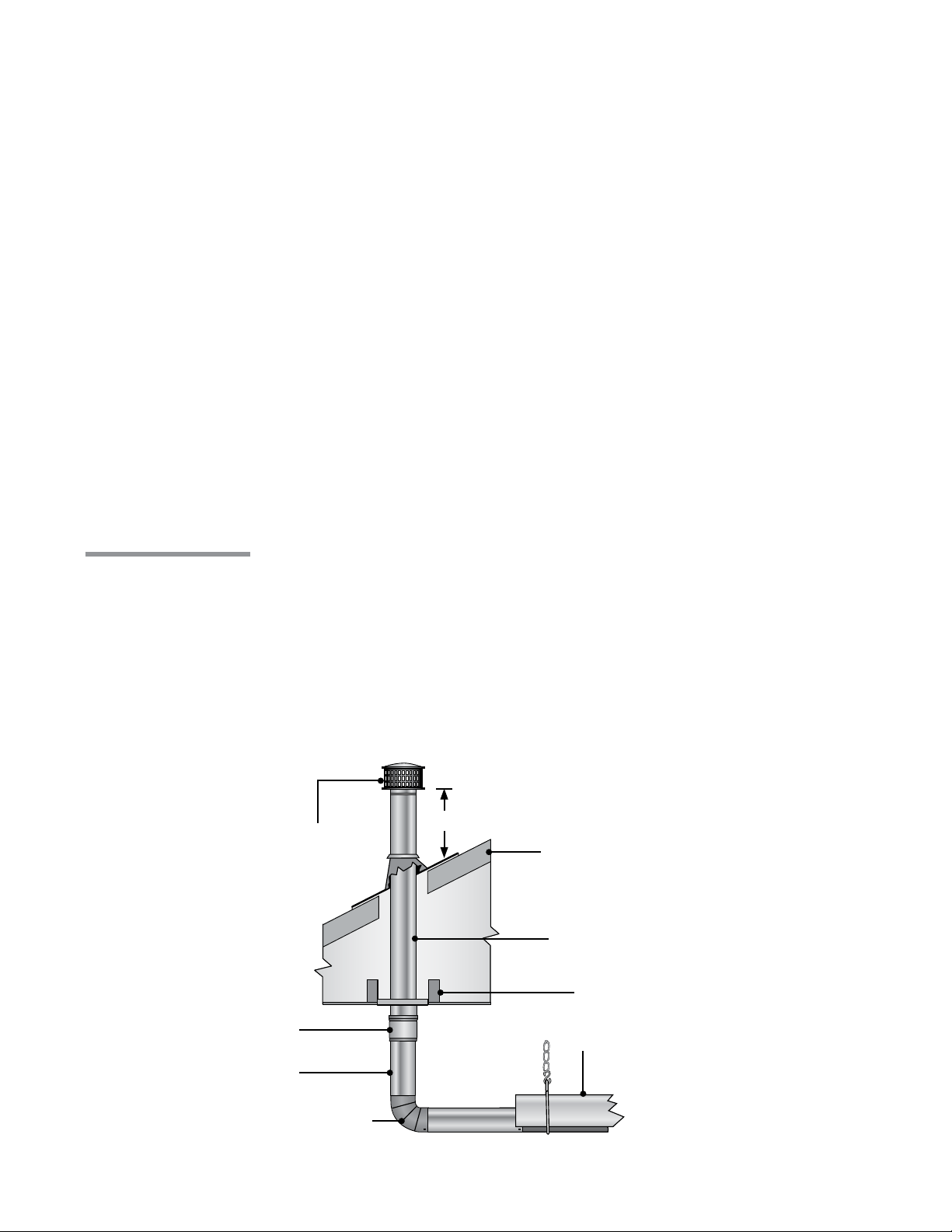
Figure 3.23 • Rooftop Venting - Side View
Vent Cap
24 in. Min.*
Roof
Double-Wall B-Vent Pipe
B to C Adapter
Single Wall Vent Pipe
Single-Wall Elbow or Alternate Tee Fitting
Firestop Spacer
Heater
*Consult the NFPA ANSI Z223.1 Gas
Vent Termination criteria if roof pitch
exc ee ds 9:12.
26
Page 27
3.0 Installation • Common Venting
Common Venting
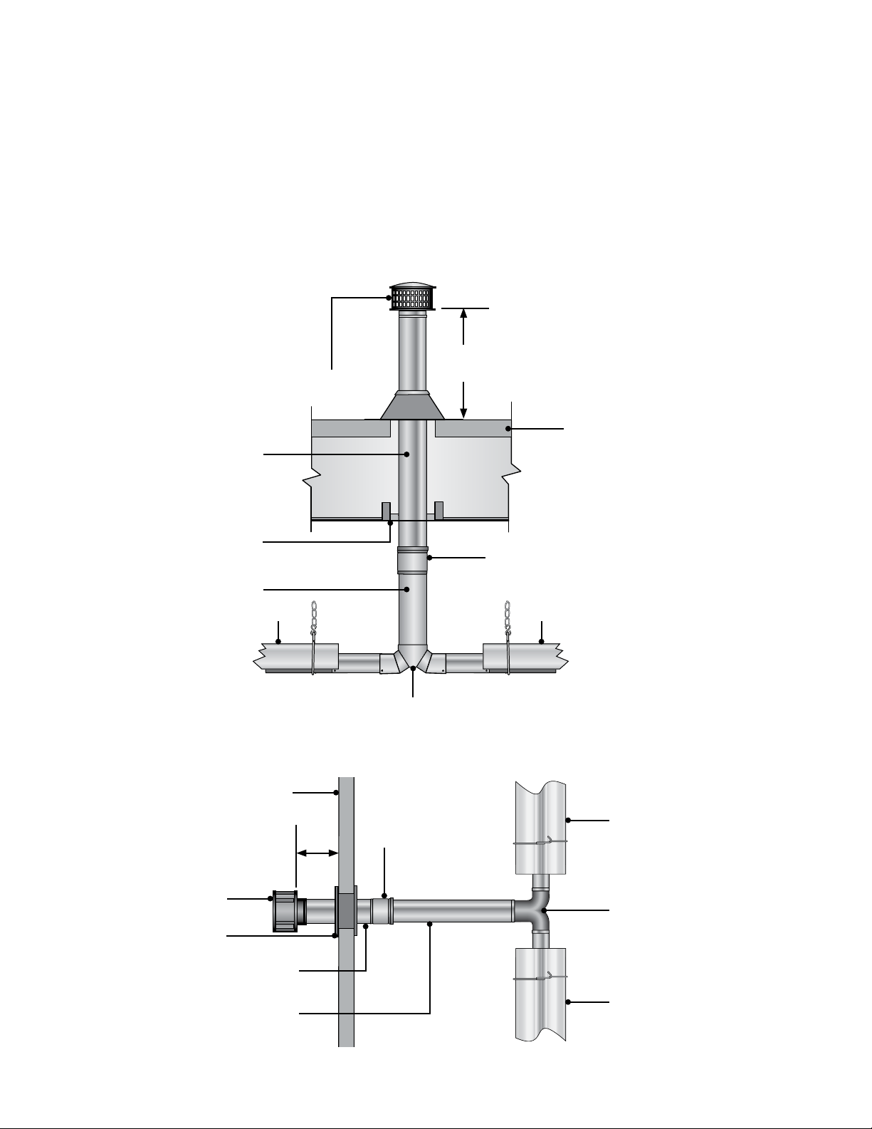
• A staggered arrangement or a dual exhaust assembly (P/N: Y) must be used when joining two
heaters to a common vent so that by-products of one heater do not flow into the adjoining vent of
the other heater.
• 6 in. diameter double-wall Type B-vent and 6 in. vent cap must be used when penetrating though a
combustible material.
• Common vented heaters must be controlled with the same thermostat. Do not operate individually.
Figure 3.24 • Common Rooftop Venting - Side View
24 in.
Rooftop Vent Cap
Double-Wall B Vent
Min.*
Roof
Firestop Spacer
Single-Wall Vent
Heater
Dual Exhaust Assembly
Figure 3.25 • Common Sidewall Venting - Top View
Sidewall
6 in.
Min.
Sidewall Vent Cap
Wall Thimble
B To C
Adapter
B to C Adapter
Heater
*Consult the NFPA ANSI Z223.1 Gas
Vent Termination criteria if roof pitch
exc ee ds 9:12.
Heater
Dual Exhaust Assembly
Double-Wall B-Vent
Single Wall Vent
Heater
27
Page 28
3.0 Installation • Optional Unvented Operation • Combustion Air Requirements
!
Optional Unvented Operation
WARNING
Not for residential use. The use of unvented tube heaters in residential indoor spaces
may result in property damage, serious injury or death. Use unvented operation in
commercial and industrial installations with proper ventilation rates only.
When using an unvented configuration, consider the following:
• A factory supplied vent cap/diffuser (P/N: WVE-GALV) must be used.
• Where unvented heaters are used, natural or mechanical means must be provided to supply
adequate ventilation - a minimum of
4 cfm/1000 BTU/h (0.38 m
3
/kW) input of installed heaters.
NOTE: Gravity or mechanical means may be used to accomplish the air displacement. Local
codes may require that the mechanical exhaust system be interlocked with the electrical supply
line to the heaters, enabling both to function simultaneously.
• The minimum clearance between the air intake and the exhaust terminal is 4 ft. NOTE: Maintain a
36” minimum distance from vent to combustion air intake on heaters fitted with a U-bend
accessory fitting.
• Exhaust openings for removing the flue products must be located above the level of the heater(s).
• Use of combustion air intake.
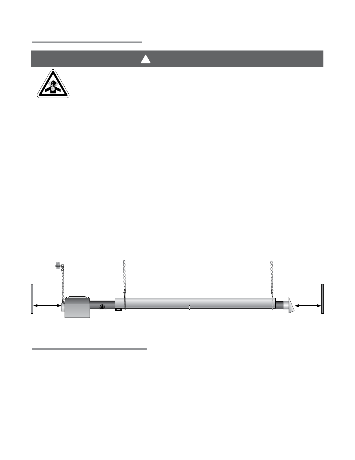
Figure 3.26 • Minimum End Clearances
12 in. Min.
All heaters
12 in. Min.
unvented
heaters
Combustion Air Requirements
Combustion air may be supplied to the heater by indoor or outdoor means.
3
If using combustion air intake from indoors, the required volume of the space must be a minimum of 50 ft
3
per 1000 BTU/h (4.8 m
/kW) unless the building is of unusually tight construction. If the building is of
unusually tight construction with air infiltration rates of less than 0.40 air changes per hour, outside
combustion air is typically needed unless the sheer size of the building allows otherwise. Contact the
factory for further determination of air infiltration rates.
28
Page 29
3.0 Installation • Combustion Air Requirements
Non-contaminated outside air for combustion must be ducted to the heater if any of the following apply:
• Chemicals such as chlorinated or fluorinated hydrocarbons (typical sources are refrigerants, solvents,
adhesives, degreasers, paints, paint removers, lubricants, pesticides, etc.).
• High humidity.
• Contaminants such as sawdust, welding smoke, etc.
• Negative building pressure.
• Unusually tight construction where there is an air infiltration rate of less the 0.40 air changes per hour.
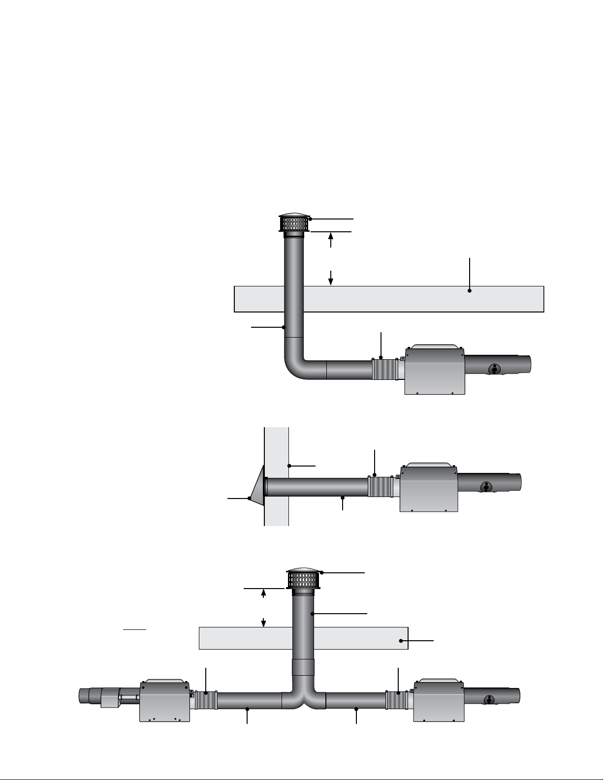
Combustion air intake may be located on either the sidewall or roof (see figure 3.27 - 3.29).
Figure 3.27
Vertical Outside Air Supply for
Single Heater Intake • Side View
4” pipe
Figure 3.28
Horizontal Outside Air Supply
for Single Heater Intake • Side View
Air Intake Cap
Roof Intake Cap
18 in.
minimum
Air Inlet Connection
Air Inlet Connection
Wall
4” pipe
Roof
(Flexible boot and band
clamps are recommended)
Burner
Control Box
(Flexible boot and band
clamps are recommended)
Burner
Control Box
Figure 3.29
Vertical Outside Air Supply
for Common Intake • Side View
NOTE: Common
intake heaters must
share the same
thermostat.
Air Inlet Connection
Burner
Control Box
18 in.
minimum
29
Roof Intake Cap
6” pipe
Roof
Air Inlet Connection
4” intake pipe4” intake pipe
(Flexible boot and band
clamps are recommended)
Burner
Control Box
Page 30
3.0 Installation • Combustion Air Requirements • Gas Supply
!
Guidelines:
Chart 3.7
Limitations for length and size of combustion air intake duct
Single Heater Intake Dual Heater Intake
Air Intake Duct Size Max. Intake Length Duct Size Max. Intake Length
4 in. 20 ft. 4 in. (single)/6 in. (dual) 20 ft.
5 in. 30 ft. 4 in. (single)/8 in. (dual) 30 ft
6 in. 40 ft.
General
• No more than two 90 degree elbows are allowed.
• Allow for expansion. Use a 4 in. flexible hose to connect the duct to the burner control box.
• In humid environments, use insulated duct, PVC pipe or DWV (drain waste vent) to prevent
condensation on the outer surface.
• Do not draw air from attic space.
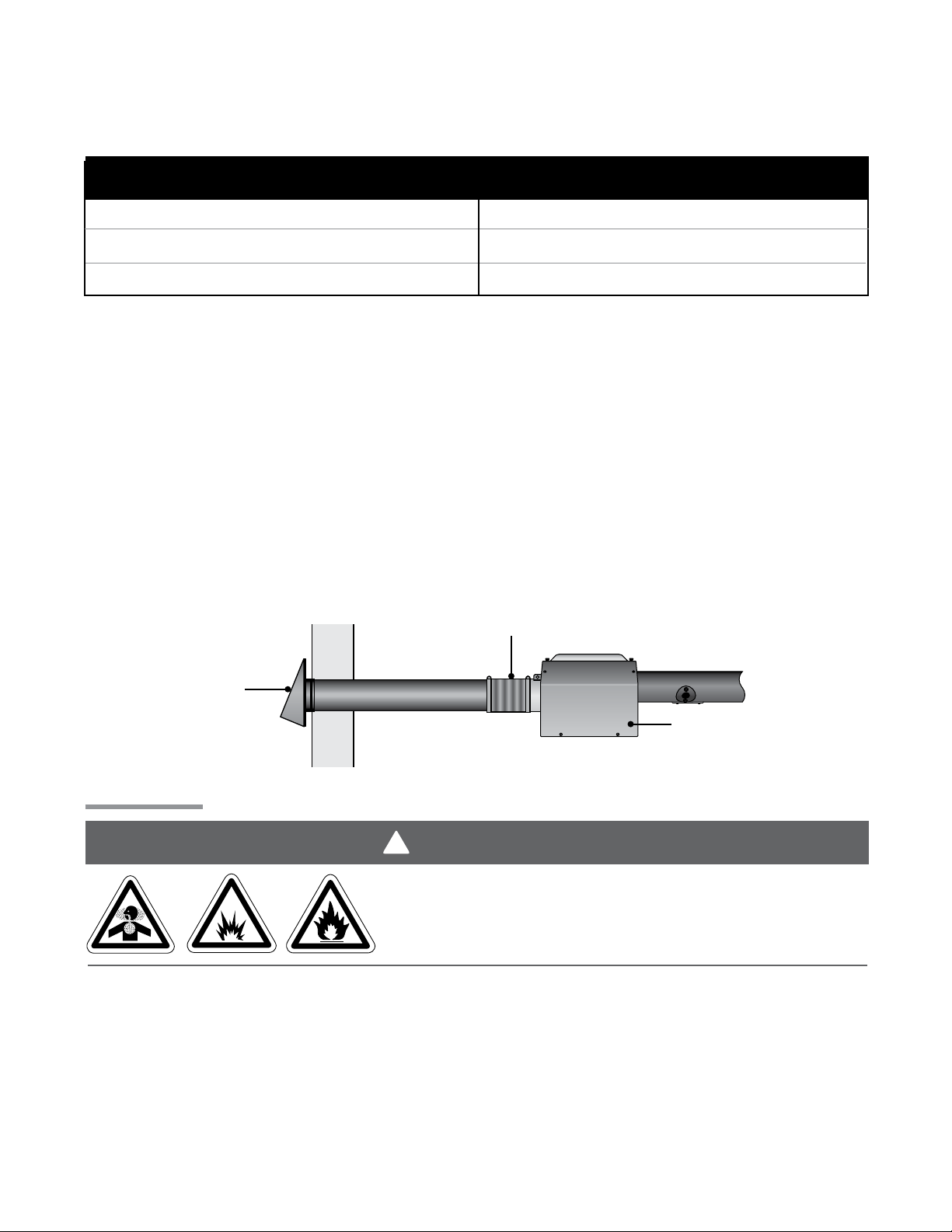
• A factory approved wall intake cap (P/N: WIV-4) must be used with horizontal outside intake
ducts. The wall intake cap (P/N: WIV-4) must be installed to prevent blockage. Locate the intake
where dirt, steam, snow, etc. will not contaminate or clog the intake screen.
• Separate air intake duct from vent pipe a minimum of 4 ft. Also, place vent pipe higher than
adjacent air intake duct.
Air Inlet Connection
Air Intake Cap
Consult factory for longer intake lengths.
(Flexible boot and band
clamps are recommended)
Burner Control Box
Gas Supply
WARNING
Improperly connected gas lines may result in fire, explosion,
poisonous fumes, toxic gases, asphyxiation or death.
Connect gas lines in accordance to national, state, provincial
and local codes.
Important! Before connecting the gas supply to the burner control box:
• Verify that the heater’s gas type (as listed on the rating plate) matches that of your application.
• Check that the gas piping and service has the capacity to handle the total gas consumption of all
heaters being installed, as well as any other gas appliances being connected to the supply line.
• Check that the main gas supply line is of proper diameter to supply the required fuel pressures.
• If utilizing used pipe, verify that its condition is clean and comparable to a new pipe. Test all gas
supply lines in accordance with local codes.
30
Page 31
3.0 Installation • Gas Supply
!
• Test and confirm that inlet pressures are correct. Refer to the heater rating plate for gas type and
the required minimum and maximum pressures (see Chart 3.8). The gas supply pipe must be of
sufficient size to provide the required capacity and inlet pressure to the heater (if necessary,
consult the local gas company). Do not exceed the maximum allowed pressures for the heater,
the space or the gas piping system.
Chart 3.8 Manifold Pressure
Type of Gas
Natural 3.5 Inches W.C. 5.0 Inches W.C. 14.0 Inches W.C.
Liquefied Petroleum 10.0 Inches W.C. 11.0 Inches W.C. 14.0 Inches W.C.
NOTE: Check manifold pressure at the tap on the gas valve. Small variations in manifold pressure (actual
vs. published) may exist due to changing atmospheric conditions. Readings will be above atmospheric
pressure.
Pressure Equivalents: 1 inch W.C. equals .058 oz/sq. in. equals 2.49 mbar.
Required Manifold
Pressure
Minimum
Inlet Pressure
Maximum
Inlet Pressure
To connect the gas:
WARNING
Failure to install, operate or service this appliance in the approved manner may result in
property damage, injury or death. Only trained, qualified gas installation and service
personnel may install or service this equipment.
The installation must conform with local building codes or, in the absence of such codes, the National Fuel
Code (NFPA 54) and in conjunction with ANSI Z21.24/CSA 6.10 “Connectors for Gas Appliances”.
Important! The heating system will expand and contract during operation. Allowances for expansion must
be made between the connection to the heater and the gas supply. Excessive bending, kinks, twists or
vibration must be avoided. A flexible gas connection of approved type is required. Flexible stainless steel
gas connectors installed in one plane, and without sharp bends, kinks or twists is recommended.
The gas pipe and connection must be supported independently. Do not install gas supply line in a manner
that bears the weight of the heater. Connect the main gas supply line with an approved flexible connector
(Figure 3.30) or, if national or local codes require rigid piping, a swing joint. See the safety messages at
the beginning of this section.
The gas outlet must be in the same room as the appliance and accessible. It may not be concealed within
or run through any wall, floor or partition. When installing the heater in a corrosive environment (or near
corrosive substances), use a gas connector suitable for the environment. Do not use the gas piping
system to electrically ground the heater.
Install a sediment trap / drip leg if condensation may occur at any point of the gas supply line. This
1
will decrease the possibility of loose scale or dirt in the supply line entering the heater’s control system
and causing a malfunction. NOTE: High pressure gas above 14 Inches W.C. (water column pressure)
requires a high pressure regulator and ball valve (field supplied).
31
Page 32
!
!
3.0 Installation • Gas Supply
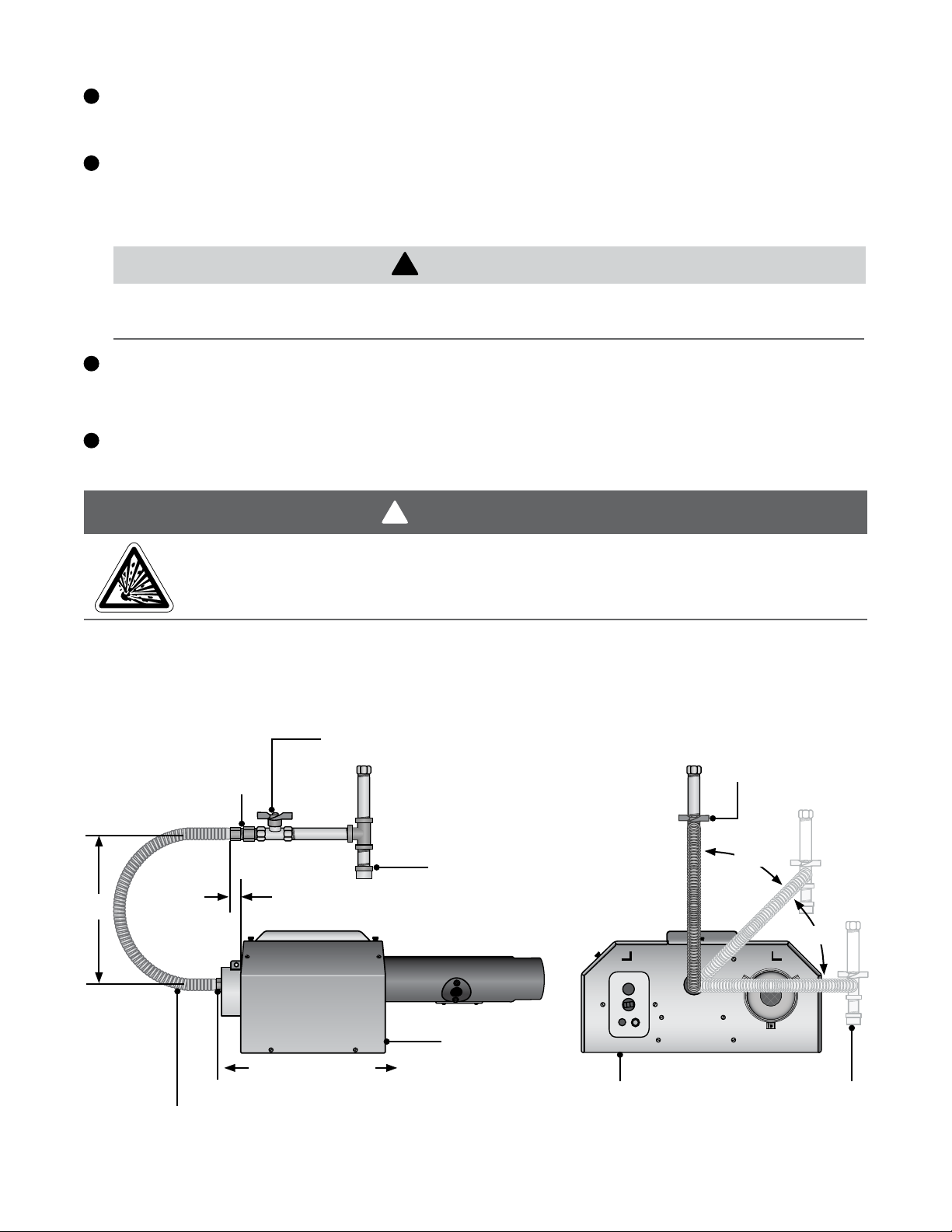
Form the stainless steel flexible connector (supplied) into a smooth C-shape allowing 12 in. between
2
the flexible connector’s end nuts (see figure 3.30).
Attach a ball valve (field supplied) to the gas supply pipe. Apply pipe compound to NPT adapter
3
threads to seal the joint. Use only a pipe compound resistant to LP.
NOTE: Provide a 1/8 in. NPT plugged tapping accessible for test gauge connection immediately
upstream of gas connection to the heater (typically provided on ball valve).
CAUTION
When using a stainless steel flexible connector, do not attach the connector nuts directly to the gas
pipe supply. Connector nuts must be installed to an approved adapter.
4
Attach the flexible connector to the adapter and burner control box inlet. Seal the joints.
NOTE: Excessive torque on the manifold may misalign the orifice. Always use two wrenches to
tighten mating pipe connections.
5
Final assembly must be tested for gas leaks according to NFPA 54 and all local codes and/or
Standards.
WARNING
Testing for gas leaks with an open flame or other sources of ignition may lead to a fire or
explosion and cause serious injury or death. Test in accordance with NFPA or local codes.
Figure 3.30 • Gas Connection (Flexible Gas
Connection shown) • Side View
NOTE: Do not exceed 14 Inches W.C. to the appliance.
Ball Valve / Inlet Tap
(Field Supplied)
Adapter
Drip Leg/
Sediment Trap
12”
2 in. max displacement
Figure 3.31 • Gas Connection (Flexible Gas
Connection shown) • End View
Ball Valve / Inlet Tap
(Field Supplied)
45°
45°
Burner
Heater Movement
Adapter
Stainless Steel Gas Connector,
formed into smooth C-Shape
Control Box
Side View
32
Burner Control Box
End View
Remove cap to clean
sediment trap.
Page 33
4.0 Operation • Lighting and Shutdown Procedures
!
4.0 Operation
WARNING
This heater is not equipped with a pilot ignition system.
Do not attempt to light the system manually.
Refer to the Series Insert Manual for any specific directions (e.g., single stage, two stage operation,
relight after a failure, etc.).
LIGHTING PROCEDURES:
1
Verify that service lid is secured.
2
Open (turn on) gas supply to the heater.
3
Close (turn on) electrical circuit (typically thermostat).
4
If the heater fails to light, turn off gas, open electrical circuit (set thermostat to lowest setting or to off).
Wait five (5) minutes before repeating above steps.
SHUTDOWN PROCEDURES:
1
Open (turn off) electrical circuit.
Close (turn off) gas supply to the heater.
2
3
Wait five (5) minutes before relighting heater.
33
Page 34
5.0 Maintenance • Maintenance Checks & Log
!
5.0 Maintenance
WARNING
Personal injury or death may result if maintenance is not performed by properly trained
gas installer or service personnel. Contact the installing distributor or place of purchase
for service. Do not operate heating system if repairs are necessary.
Allow heater to cool prior to servicing.
Disconnect power to heater before servicing.
Use protective glasses when maintaining the heater.
Routine Inspection:
At least once per year, the heating system should be inspected and serviced by trained gas installation
and service personnel only. This inspection should be performed at the beginning of the heating
season to insure that all heater components are in proper working order and that the heating system
operates at peak performance. Particular attention should be paid to the following items.
• Blower Motor: Annual oiling of the blower motor with SAE oil will extend bearing life significantly.
Motors with sealed ball bearings (no oil ports) do not require oiling. Ensure that the squirrel cage in
the blower is kept clean. If dirt becomes a problem, installation of outside air intake ducts for
combustion is recommended.
Check lubrication instructions on motor. If oiling is required,
add three to four drops of SAE 20 electric motor oil:
• After three years or 25,000 hours of operation (light-duty)
• After two years or 8,000 hours of operation (medium-duty)
• Annually or after 1,500 hours of operation (heavy-duty)
• Vent pipe system: Check the outside termination and the connections at the heater. Inspect the vent
exhausts for leakage, damage, fatigue, corrosion and obstructions. If dirt becomes a problem,
installation of outside air intake ducts for combustion is recommended.
• Combustion air intake system (when applicable): Check for blockage and/or leakage. Check the
outside termination and the connection at the heater.
• Heat exchangers: Check the integrity of the heat exchangers. Replace if there are signs of structural
failure. Check for corrosion and/or buildup within the tube exchanger passageways.
• Burner: Check for proper ignition, burner flame and flame sense. Flame should extend directly
outward from burner without floating or lifting.
• Wiring: Check electrical connections for tightness and/or corrosion. Check wires for damage.
• Gas Connection: Inspect the integrity of the gas connection to the heater. Check for leaks, damage,
fatigue or corrosion. Do not operate if repairs are necessary and turn off gas supply to the heater.
Contact service personnel.
Never over-oil the motor, or
premature failure may occur.
NOTICE
• Reflectors: Inspect the integrity of the reflectors for damage, separation, missing or misaligned
sections. Do not operate if repairs are necessary. Repair or replace as required per the general
installation manual. To maintain effective infrared heating, always keep both sides of the reflector
clean. Dirt and dust can be vacuumed up or wiped with a soap and water solution. Use metal polish
if the reflectors are severely dirty.
Contact service personnel if repairs are necessary. Do not operate unit.
34
Page 35
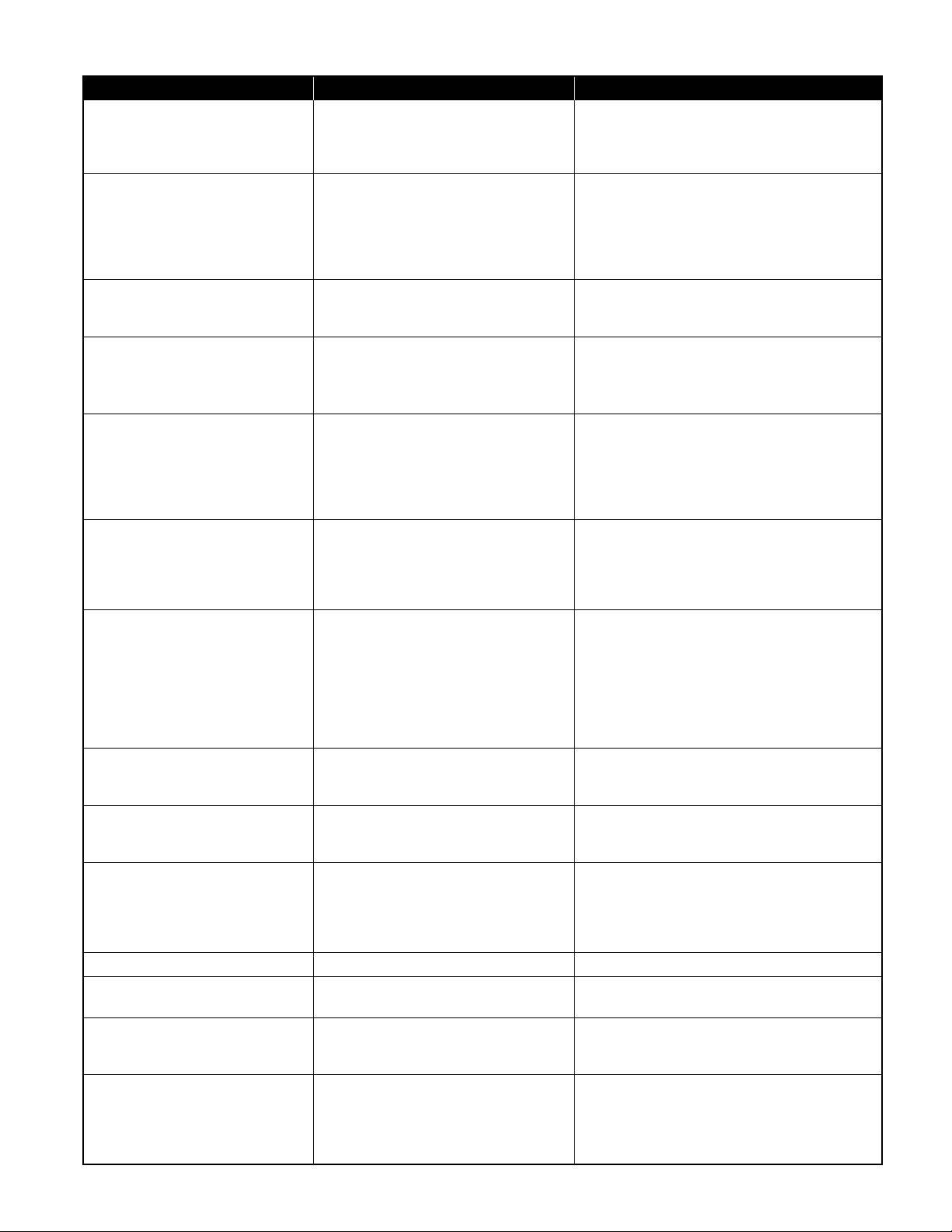
Chart 5.1 Troubleshooting Guide
Symptom Possible Cause Corrective Action
Thermostat closed, fan doesn’t
operate.
Thermostat closed. Fan
operates. Switch does not close.
Thermostat closed. Fan
operates. Pressure switch
closes. No glo-bar igniter.
Thermostat closed. Fan
operates. Pressure switch close.
Glo-bar energizes. Valve does
not open.
• Blown fuse.
• Faulty thermostat.
• Loose or disconnected wire.
• Faulty fan.
• Loose or disconnected wire.
• Box lid or gasket not in place.
• Plugged pressure switch lines.
• Plugged or restricted exhaust vent.
• Baffle location incorrect.
• Faulty pressure switch.
• Faulty glo-bar igniter.
• Faulty circuit board.
• Disconnect gas valve wires.
• Faulty circuit board.
• Faulty gas valve.
• Replace.
• Replace.
• Repair as required.
• Lubricate, repair or replace.
• Repair as required.
• Put in place.
• Clean as necessary.
• Remove foreign matter.
• Re-position baffles at vent end.
• Replace only. Do not adjust.
• Replace.
• Replace.
• Repair as required.
• Replace.
• Replace.
Thermostat closed. Fan and
glo-bar /spark igniter operate.
Ignition occurs, burner cycles
off in less than 60 seconds.
Thermostat closed. Fan and globar /spark igniter operate. After
45 seconds glo-bar shuts off
(15 seconds for spark igniter).
No ignition.
Loss of heater efficiency. • Low gas pressure.
Radiant tube leaking burnt
gases.
Condensation. • Stack length is too long.
Tube bowing. • Insufficient combustion air.
Tube corroding. • Contaminated combustion air. • Provide fresh air inlet duct.
Visual inspection of burner
operation not possible.
Stack sooting. • Insufficient combustion air.
Odor or fumes in space
(normal during first firing and
will subside after initial burn off,
approximately 20 minutes).
• Low gas pressure.
• Baffle improperly positioned.
• Faulty pressure switch.
• Restricted flue vent.
• No electrical ground.
• Reversed polarity.
• Closed gas supply.
• Dirty or restricted orifice.
• Faulty valve. Disconnected wire.
• Inlet pressure exceeds 14 inches
W.C.
• Dirty or restricted orifice.
• Foreign matter inside burner.
• Unit cycles on and off.
• Reflector is dirty.
• Reflector not in place.
• Clogged fan blower.
• Loose tube connections.
• Holes or cracks in radiant tubes.
• Light gauge vent stack used.
• Contaminated combustion air.
• Over fired.
• Contaminated combustion air.
• Heater unable to expand properly.
• Dirty or sooted sight glass.
• Unit mounted upside-down.
• Improper gas.
• Dirty fan or blockage.
• Vaporized solvents decomposing
when contacting radiant tubes.
• Evaporation of oils, solvents at floor
level.
• Loose tube / vent connections.
• Provide required gas pressure.
• Re-position baffle at vent end.
• Replace.
• Remove foreign matter.
• Connect electrical ground to junction box.
• Repair.
• Open all gas connections.
• Remove. Clean with a soft object.
• Replace or repair.
• Lower inlet pressure.
• Provide required gas pressure.
• Remove. Clean with a soft object.
• Clean as necessary.
• Check previous symptom.
• Clean with aluminum cleaner and soft
cloth.
• Put in place.
• Clean.
• Ensure that tubes are fully connected
and clamped properly.
• Replace.
• Shorten stack length.
• Minimum of 26 ga. vent pipe required.
• Provide fresh air inlet duct.
• Provide 1 sq. in. of free air for every
5,000 BTU/h of input.
• Check gas pressure and orifice size.
• Provide fresh air inlet duct.
• Remount with flexible inlet or vent pipe.
• Remove, clean or replace.
• Mount correctly.
• Provide 1 sq. in. of free air for every
5,000 BTU/h of input.
• Correct with proper gas input (or clean).
• Provide proper ventilation.
• Provide proper ventilation.
• Tighten tube clamps to 40-60 ft-lb.
• Seal vent pipes.
35
Page 36

6.0 Limited Warranty
6.0 Limited Warranty
One-Year Limited Warranty. Radiant Tube Heaters covered in this manual, are warranted by Detroit Radiant Products
Company to the original user against defects in workmanship or materials under normal use for one year after date of
purchase. Any part which is determined to be defective in material or workmanship and returned to an authorized service
location, as Detroit Radiant Products Company designates, shipping costs prepaid, will be, as the exclusive remedy, repaired
or replaced at Detroit Radiant Products Company’s option. For limited warranty claim procedures, see PROMPT
DISPOSITION below. This limited warranty gives purchasers specific legal rights which vary from jurisdiction to jurisdiction.
Additional Limited Warranty. In addition to the above mentioned one-year warranty, Detroit Radiant Products Company
warrants the original purchaser an additional extension on the combustion chamber, radiant tubes and stainless steel burner.
This extension excludes electrical/purchased components. See specific product warranties on page 20 of the Series Insert
Manual that accompanied this piece.
General Conditions. The Company will not be responsible for labor charges for the analysis of a defective condition of the
heater or for the installation of replacement parts. The warranties provided herein will not apply if the input of the heater
exceeds the rated input at time of manufacturing or if the heater in the judgment of the Company has been subjected to
misuse, excessive dust, improper conversion, negligence, accident, corrosive atmospheres, excessive thermal shock,
excessive vibration, physical damage to the heater, alterations by unauthorized service personnel, operation contrary to the
Company’s instructions or if the serial number has been altered, defaced, or removed. The Company shall not be liable for
any default or delay in the performance of these warranties caused by contingency beyond its control, including war,
government restriction or restraints, strikes, fire, flood, short or reduced supply of raw materials, or parts.
The warranties herein shall be null and void if the heater is not installed by a competent heating contractor and/or if the
heater is not installed according to Company instructions, normal industry practices and/or if the heater is not maintained
and repaired according to Company’s instructions. Normal product degradation and wear (rust, oxidation, etc.) does not
constitute a material defect and applicable warranty claim.
Limitation of Liability. To the extent allowable under applicable law, Detroit Radiant Products Company’s liability for
consequential and incidental damages is expressly disclaimed. Detroit Radiant Products Company’s liability in all events is
limited to and shall not exceed the purchase price paid.
Warranty Disclaimer. Detroit Radiant Products Company has made a diligent effort to provide product information and
illustrate the products in this literature accurately; however, such information and illustrations are for the sole purpose of
identification, and do not express or imply a warranty that the products are merchantable, or fit for a particular purpose, or that
the products will necessarily conform to the illustrations or descriptions. Except as provided below, no warranty or affirmation
of fact, expressed or implied, other than as stated in the “LIMITED WARRANTY” above is made or authorized by Detroit
Radiant Products Company.
Product Suitability. Many jurisdictions have codes and regulations governing sales, construction, installation, and/or use of
products for certain purposes, which may vary from those in neighboring areas. While Detroit Radiant Products Company
attempts to assure that its products comply with as many codes, it cannot guarantee compliance, and cannot be responsible
for how the product is installed or used. Before purchase and use of a product, review the product applications, and all
applicable national and local codes and regulations, and be sure that the product, installation, and use will comply with them.
Certain aspects of disclaimers are not applicable to consumer products: e.g., (a) some jurisdictions do not allow the exclusion
or limitation of incidental or consequential damages, so the above limitation or exclusion may not apply to you: (b) also, some
jurisdictions do not allow a limitation on how long an implied warranty lasts, consequently the above limitation may not apply
to you: and (c) by law, during the period of this limited warranty, any implied warranties of implied merchantability or fitness for
a particular purpose applicable to consumer products purchased by consumers, may not be excluded or otherwise
disclaimed.
Prompt Disposition. Detroit Radiant Products Company will make a good faith effort for prompt correction or other
adjustment with respect to any product which proves to be defective within limited warranty. For any product believed to be
defective within limited warranty, first write or call dealer from whom the product was purchased. Dealer will give additional
directions. If unable to resolve satisfactorily, write to Detroit Radiant Products Company at address below, giving dealer’s
name, address, date and number of dealer’s invoice, and describe the nature of the defect. Title and risk of loss pass to buyer
on delivery to common carrier. If product was damaged in transit to you file claim with carrier.
Registration. Register on-line at www.detroitradiant.com /warranty.
© 2013 Detroit Radiant Products Co.
21400 Hoover Road • Warren, MI 48089
Phone: (586) 756-0950 Fax: (586) 756-2626
Printed in U. S. A.
www.detroitradiant.com • [email protected]
36
 Loading...