

Page 1
!
!
Detroit Radiant Products Co.
PT Series Manual
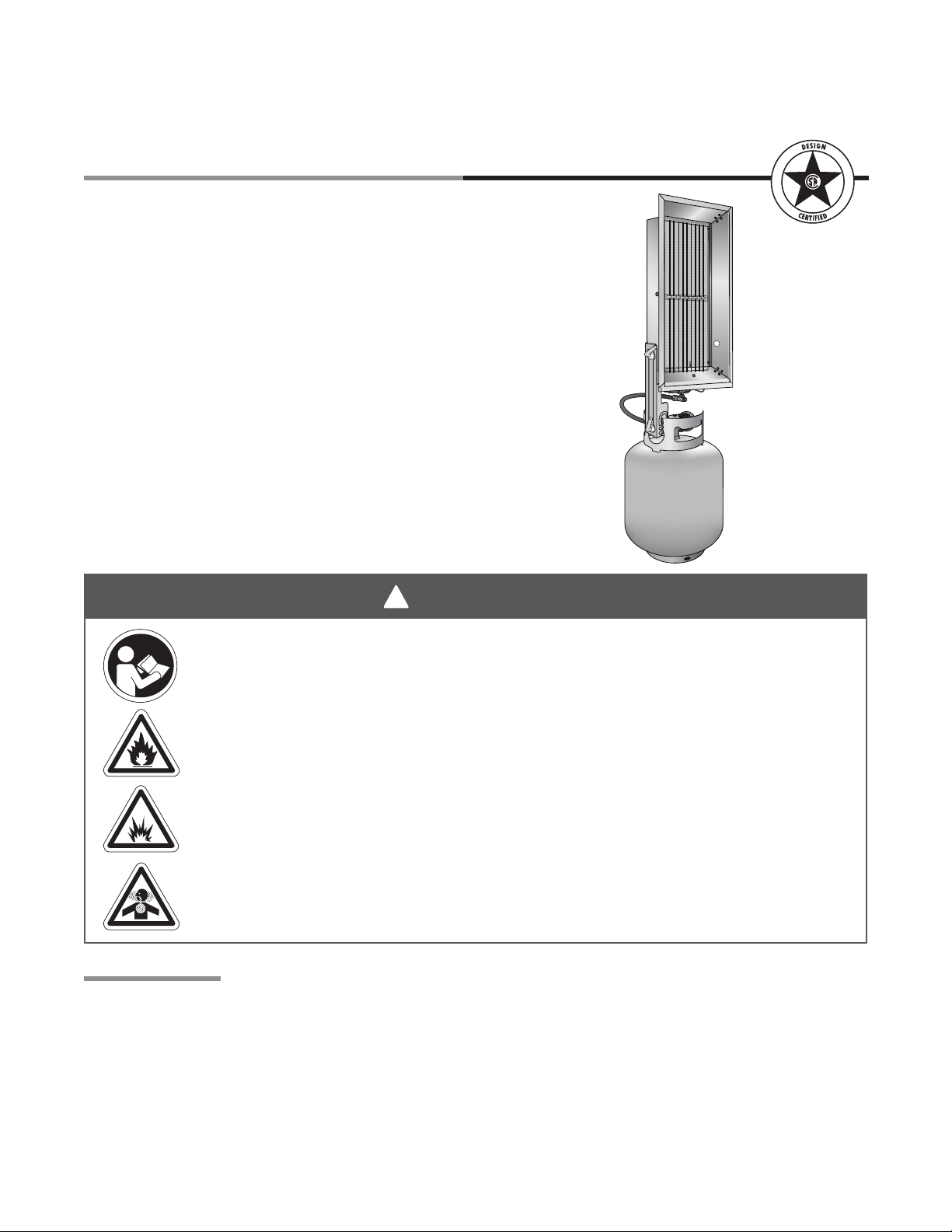
Models P-16T & P-32T
Installation
Operation
Maintenance
and Parts
Important! The LP gas heater is designed and
approved for use as a construction heater in
accordance with the ANSI Z83.7a-2007 Standard.
Other standards govern the use of fuel gases and
heat producing products in specific applications.
Check with local authorities if you have questions or
need advice about applications.
WARNING
Failure to comply with the precautions and instructions provided with this heater can
result in death, serious bodily injury and property loss or damage from hazards of fire,
explosion, burns, asphyxiation, carbon monoxide poisoning, and / or electrical shock.
Only persons who can understand and follow the instructions should use or service
this heater. If you need assistance or heater information such as an instruction manual,
label, etc. contact the manufacturer.
Fire, burn, inhalation, and explosion hazard. Keep combustibles such as building
materials, paper or cardboard, a safe distance away from the heater as recommended
by the instructions. Never use the heater in spaces which do or may contain volatile or
airborne combustibles or products such as gasoline, solvents, paint thinner, dust
particles or unknown chemicals.
This heater is not approved for use in any indoor residential application. This
includes, but is not limited to, attached garages, solarium, living quarters, mobile
homes, campers, tents, recreational vehicles etc.
For Your Safety
Propane gas is VERY FLAMMABLE! It is scented and its strong odor is readily detectable. In the event of
a leak, propane will accumulate and the possibility of a fire is present. If you smell gas:
• Never strike a match, create a flame or an electric spark.
• Move the heater outside and ventilate the area thoroughly.
• Find and correct the source of the leak before attempting to light the heater. If the leak cannot be
corrected, do not tamper with the heater.
• Turn the heater “OFF” and consult the manufacturer, a qualified installer or the gas supplier.
Keep these instructions for future reference.
Replaces: LIOPT-3M-10/10 (CDS)
LIOPT-Rev. 29110
Print: LIOPT-1M-6/12 (CDS)
Page 2

PT Series
3
Contents
1.0 Safety. . . . . . . . . . . . . . . . . . . . . . . . . . . . . . . . . . . . . . . . . . . . . . . . . . . . . . . . . . . . . . . . . . . . .3
Warning Symbols. . . . . . . . . . . . . . . . . . . . . . . . . . . . . . . . . . . . . . . . . . . . . . . . . . . . . . . . . . . . 3
Applications . . . . . . . . . . . . . . . . . . . . . . . . . . . . . . . . . . . . . . . . . . . . . . . . . . . . . . . . . . . . . . . .3
Clearance to Combustibles . . . . . . . . . . . . . . . . . . . . . . . . . . . . . . . . . . . . . . . . . . . . . . . . . . . .4
Safety Signs and Labels . . . . . . . . . . . . . . . . . . . . . . . . . . . . . . . . . . . . . . . . . . . . . . . . . . . . . . 5
2.0 Installation . . . . . . . . . . . . . . . . . . . . . . . . . . . . . . . . . . . . . . . . . . . . . . . . . . . . . . . . . . . . . . . . 6
Installation . . . . . . . . . . . . . . . . . . . . . . . . . . . . . . . . . . . . . . . . . . . . . . . . . . . . . . . . . . . . . . . . . 6
Heater Dimensions. . . . . . . . . . . . . . . . . . . . . . . . . . . . . . . . . . . . . . . . . . . . . . . . . . . . . . . . . . . 7
Mounting the Heater. . . . . . . . . . . . . . . . . . . . . . . . . . . . . . . . . . . . . . . . . . . . . . . . . . . . . . . . . . 8
3.0 Operation . . . . . . . . . . . . . . . . . . . . . . . . . . . . . . . . . . . . . . . . . . . . . . . . . . . . . . . . . . . . . . . . . 9
4.0 Maintenance . . . . . . . . . . . . . . . . . . . . . . . . . . . . . . . . . . . . . . . . . . . . . . . . . . . . . . . . . . . . . . 10
5.0 Parts . . . . . . . . . . . . . . . . . . . . . . . . . . . . . . . . . . . . . . . . . . . . . . . . . . . . . . . . . . . . . . . . . 11
6.0 Repair . . . . . . . . . . . . . . . . . . . . . . . . . . . . . . . . . . . . . . . . . . . . . . . . . . . . . . . . . . . . . . . . . 12
7.0 Limited Warranty . . . . . . . . . . . . . . . . . . . . . . . . . . . . . . . . . . . . . . . . . . . . . . . . . . . . . . . . . . 12
2
Page 3
!
!
!
!
PT Series
!
!
1.0 Safety • Warning Symbols • Applications
1.0 Safety
WARNING
Improper installation, adjustment, alteration, service or maintenance can cause
property damage, injury or death. All persons involved with the operation and
maintenance of this heater must read and understand the information in this manual
before use or service of the heater.
Warning Symbols
Safety is the most important consideration during installation, operation and maintenance of the infrared
heater. You will see the following symbols and signal words when there is a hazard related to safety or
property damage.
Warning indicates a potentially hazardous situation
WARNING
which, if not avoided, could result in death or injury.
Caution indicates a potentially hazardous situation
CAUTION
NOTICE
which, if not avoided, could result in minor or
moderate injury.
Notice indicates a potentially hazardous situation
which, if not avoided, could result in property
damage.
WARNING
Not For Indoor Residential Use. Operating an infrared heater system in
residential indoor spaces may result in property damage, serious injury or death.
Use this heater in open, well ventilated space only.
Applications
This is not an explosion proof heater. Consult your local Fire Marshall, insurance carrier and other
authorities for approval of location and use of the heater.
Construction
The primary use of construction heaters is to provide temporary heating of buildings under construction,
alteration or repair. It may also be used to provide temporary emergency heat. This heater is not to be
used in the home, mobile homes, campers, tents, recreational vehicles etc.
For maximum safety, the building must be evaluated for potential hazards before locating and using the
heater. A critical safety factor to consider before installation is the clearance to combustibles (see page 4).
3
Page 4
5
1.0 Safety • Clearance to Combustibles
!
PT Series
Clearance to Combustibles
WARNING
Improperly connected gas line may result in serious injury or death, explosion, poisonous
fumes, toxic gases, asphyxiation. Connect gas lines in accordance to national, state,
provincial and local codes.
Placement of explosive objects, flammable objects, liquids and vapors close to the heater
may result in explosion, fire, property damage, serious injury or death. Do not store, or use,
explosive objects, liquids and vapor in the vicinity the heater.
Failure to comply with the published clearances to combustibles could result in personal
injury, death and/or property damage.
When deciding on a location for the heater, the minimum clearances to combustibles must be maintained.
These distances are shown in Chart 1.1. If you are unsure of the potential hazards, consult your local Fire
Marshall, insurance carrier or other qualified authorities on the application of gas fired infrared heaters for
approval of the proposed location.
Hazards:
For maximum safety the building must be evaluated for hazards before locating the heater system.
Examples include, but not limited to:
• Gas and electrical lines
• Combustible and explosive materials
• Chemical storage areas
• Areas of high chemical fume concentrations
A critical safety factor to consider before placement is the clearances to combustibles. Clearance to
combustibles is defined as the minimum distance you must have between the infrared surface, or
reflector, and the combustible item. Considerations must also be made for moving objects around the
infrared heater. The following is a partial list of items to maintain clearances from:
• Provisions for accessibility to the heater
• Combustion and ventilating air supply
• Vehicle parking areas
• Dirty, contaminated environment
Combustible items: Moving Objects:
• Wood • Overhead doors
• Paper • Vehicle lifts
• Fabric • Cranes
• Chemicals • Hoists
• Wall or roof insulation • Car wash equipment
• Rags or towels
IMPORTANT! Locate the unit at least 10 feet away from canvas, tarpaulins or similar coverings and
secure such coverings to prevent ignition and interference with the heater. It is the responsibility of the
installer to ensure that building materials with a low heat tolerance, which may degrade at lower
temperature, are protected to prevent degradation.
4
Page 5
PT Series
1.0 Safety • Clearance to Combustibles • Safety Signs and Labels
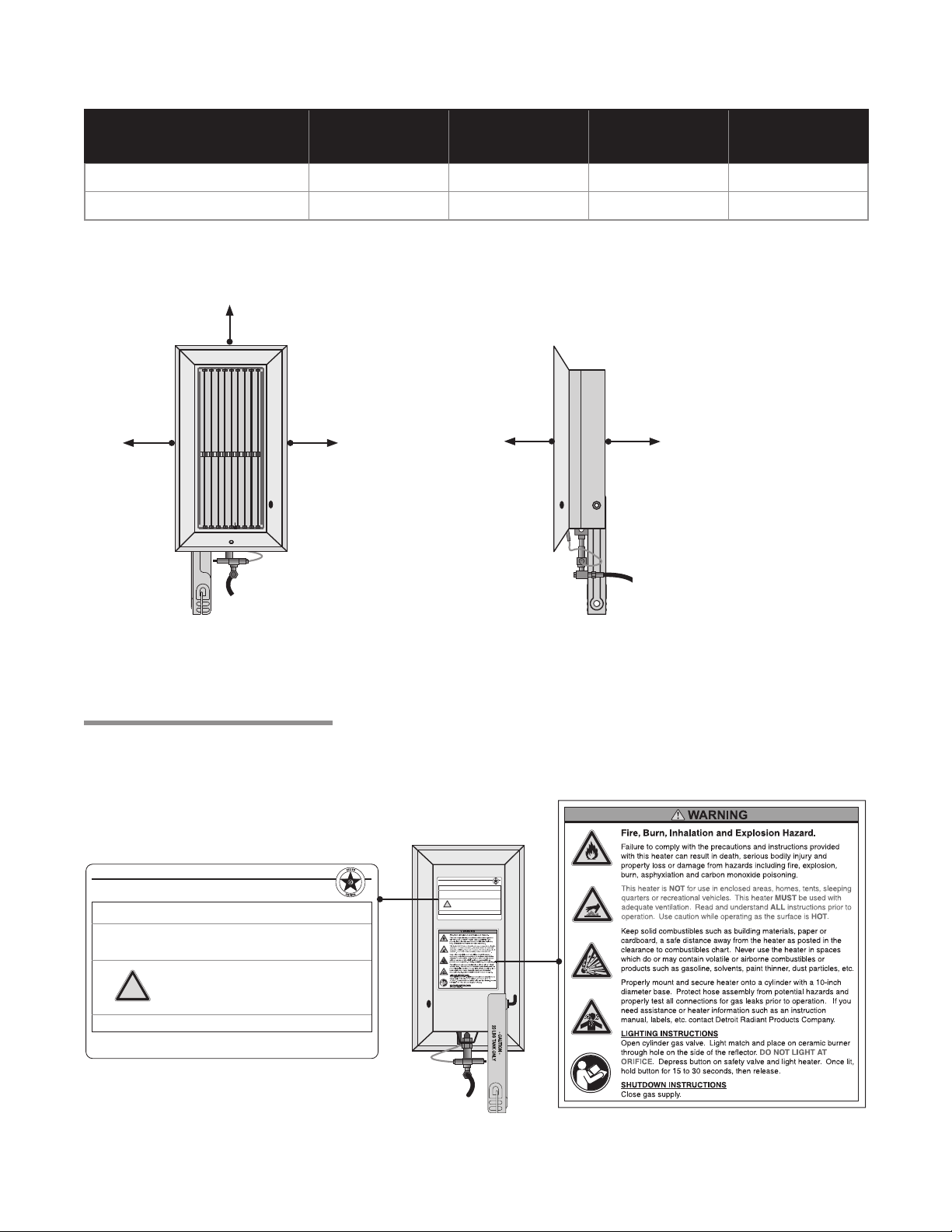
Chart 1.1 • Clearance to Combustibles (in Inches)
Model No. Sides Back Top Front
P-16T 18 18 48 48
P-32T 24 18 48 72
Figure 1.1 • Clearance to Combustibles
Top
Side
Side
FRONT VIEW
Front
Back
SIDE VIEW
Safety Signs and Labels
Safety warning labels must be maintained on the infrared heater. Illustrations of the safety labels, and their
locations, are pictured below.
DETROIT RADIANT PRODUCTS - RADIANT HEATER
PORTABLE INFRARED CONSTRUCTION HEATER
FOR INDOOR (NON-DOMESTIC) INSTALLATION ONLY
MODEL NO.
P - 32T
INPUT BTU/H:
16,000
MANIFOLD PRESSURE:
11.0 Inches W.C.
!
DESIGN COMPLIES WITH:
ANSI Z83.7-2000-GAS FIRED CONSTRUCTION
DETROIT RADIANT PRODUCTS COMPANY
21400 HOOVER ROAD - WARREN , MI
(586) 756-0950 - www.drp-co.com
FOR USE WITH PROPANE GAS
GAS INLET PRESSURE TO REGULATOR:
MINIMUM CLEARANCES FROM COMBUSTIBLE
MATERIAL AND FUEL CONTAINERS
SAMPLE
SIDES REAR CEILING DISCHARGE
24 In. 18 In. 48 In. 72 In.
Rating Plate
Minimum: 12.0 Inches W.C.
Maximum: 350 PSI
Serial No.: 0807 DETR 21400 0001
DETROIT RADIANT PRODUCTS - RADIANT HEATER
PORTABLE INFRARED CONSTRUCTION HEATER
FOR INDOOR (NON-DOMESTIC) INSTALLATION ONLY
MODEL NO.
P - 32T
INPUT BTU/H:
MANIFOLD PRESSURE:
16,000
11.0 Inches W.C.
MINIMUM CLEARANCES FROM COMBUSTIBLE
MATERIAL AND FUEL CONTAINERS
!
SIDES REAR CEILING DISCHARGE
24 In. 18 In. 48 In. 72 In.
DESIGN COMPLIES WITH:
ANSI Z83.7-2000-GAS FIRED CONSTRUCTION
DETROIT RADIANT PRODUCTS COMPANY
21400 HOOVER ROAD - WARREN, MI
(586) 756-0950 - www.drp-co.com
FOR USE WITH PROPANE GAS
GAS INLET PRESSURE TO REGULATOR:
Minimum: 12.0 Inches W.C.
Maximum: 350 PSI
Serial No.: 0807 DETR 21400 0001
BACK VIEW
5
Safety Label F/N: LLPCL001
Page 6
7
!
2.0 Installation • Assembly
2.0 Installation
Read and understand, the installation, operating and maintenance instructions thoroughly
before assembling or operating this equipment.
Insufficient ventilation may result in fire, explosion, health problems, carbon monoxide
poisoning, serious injury or death. Vent enclosed spaces and buildings according to national,
state, provincial and local codes.
Overfilled LP gas cylinders may cause explosion, fire, property damage, serious injury or
death. Indications of an overfilled LP gas cylinder include failure to light and/or pressure
buildup on the regulator. Return overfilled tank to the supplier and inspect the hose and
regulator for damage.
PT Series
WARNING
Using any heater component (e.g., manifold, gas valve, gas line connector) for support may
result in the heater tipping over and causing injury, fire or explosion. Always locate the
heater on a stable, secure and level surface.
Installation
Prior to installation, verify the heater’s gas type as listed on the rating plate. Installation of this heater must
conform with local codes or, in the absence of local codes, with the Standard for the Storage and
Handling of Liquefied Petroleum Gases, ANSI/NFPA 58 and the Natural Gas and Propane Installation
Code, CSA B149.1.
LP gas models are approved for use with a DOT 20 lb. LP gas cylinder with a 10 inch diameter base
(NOTE: only use a vapor withdraw type cylinder. Do not use a forklift truck or liquid dispensing cylinder).
See Chart 2.2 Operating Values for pressure specifications.
Along with maintaining the clearance to combustibles, the heater must be used in a well ventilated area.
When the heater is temporarily used in an enclosed area, a positive air displacement of at least 4.0 CFM
per 1,000 BTU/h of the heater’s rated input must be provided.
Locate the heater on a stable, level surface and at least 10 feet away from canvas, tarpaulins or similar
coverings and secure such coverings to prevent ignition and interference with the heater. The heater must
be at least 6 ft. from other LP gas containers and have at least 20 ft. between containers in the direction of
the projected heat.
The use of the heater in drafty conditions may result in the loss of heater efficiency. In drafty conditions
turn the heater so it faces away from the direction of the draft/wind. The heater must be placed or installed
such that it is not directly exposed to water spray, rain and/or dripping water.
6
Page 7
PT Series
2.0 Installation • Heater Dimensions • Mounting LP Gas Model
The heater contained in this carton has been factory assembled and is in an operable condition without
the need of adjustment or further assembly. Only use the pressure regulator (and hose, LP only) supplied
with the heater. Alteration of the heater or replacement of components not specified by Detroit Radiant
Products Co. voids all approvals and warranties.
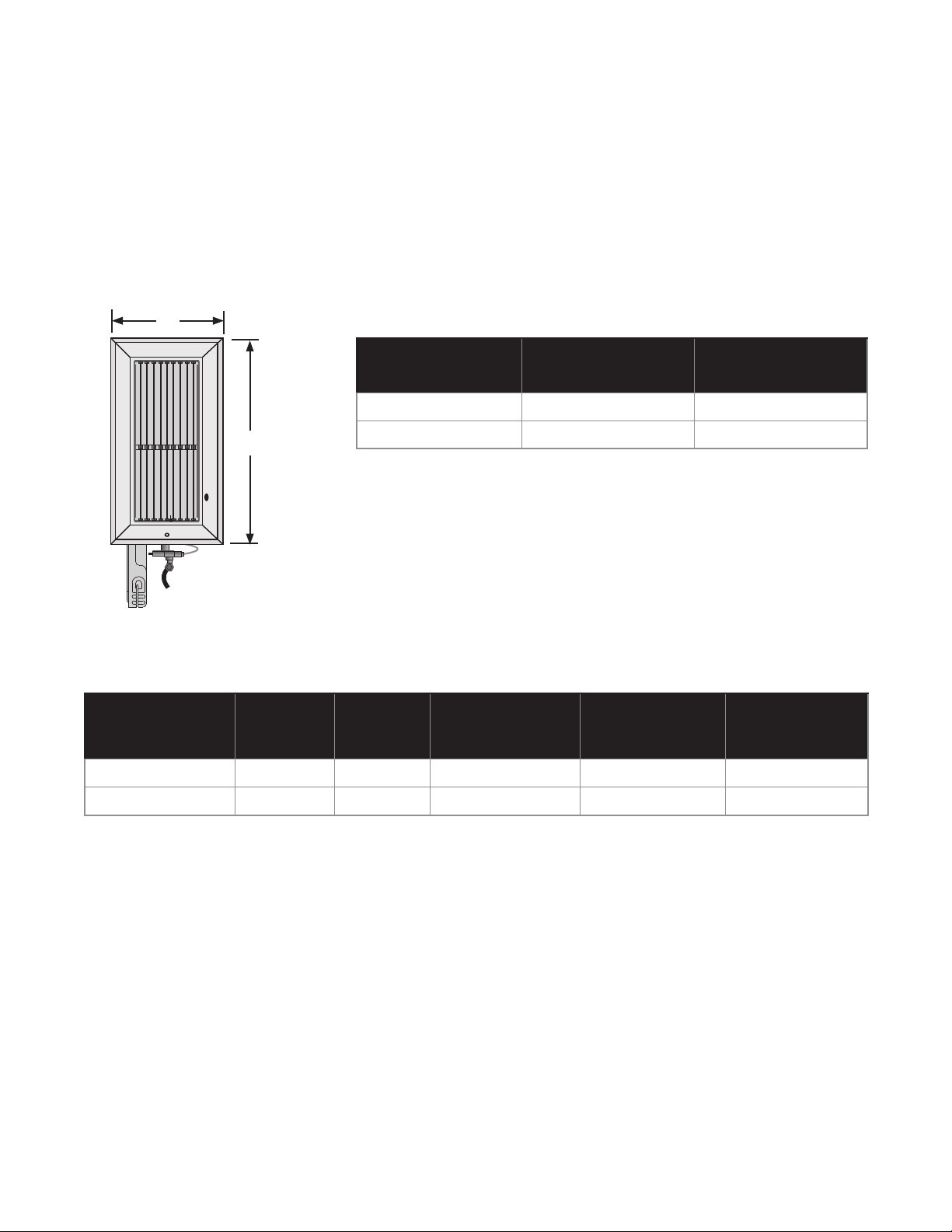
Figure 2.1 • Heater Dimensions
X
Y
Chart 2.2
• Operating Values
Model No. BTU/h Gas Type
P-16T 16,000 LP 11 Inches W.C. 12 Inches W.C. 350
Chart 2.1 • Heater Dimensions (in Inches)
Model No. Dim “X” Dim “Y”
P-16T 10 1/16 13 1/8
P-32T 10 1/16 18 5/8
Manifold
Pressure
Minimum Inlet
Pressure
(W.C.P.) *
Maximum Inlet
Pressure
(PSI)
P-32T 32,000 LP 11 Inches W.C. 12 Inches W.C. 350
* For purpose of adjustment
7
Page 8
9
2.0 Installation • Mounting the Heater
!
PT Series
WARNING
Improperly connected gas lines may result in fire, explosion,
poisonous fumes, toxic gases, asphyxiation and death. Connect
gas lines in accordance to national, state and local codes.
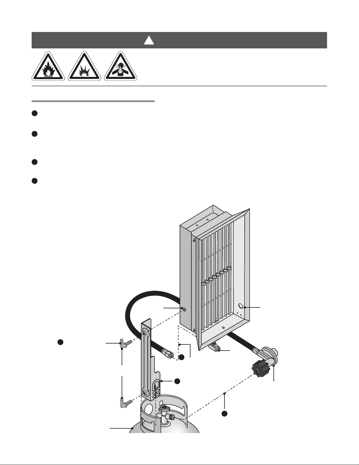
Mounting the Heater (P-16T, P-32T)
1
Attach the mounting bracket to the heater by lining up the upper hole of the bracket with the mounting
hole located on the side of the heater. Fasten the two parts with the 3/8-16 thumbscrew provided.
2
Connect and hand tighten the included pressure regulator to the LP gas cylinder. Turn the nut
(clockwise) until it stops. Do not use a wrench or over tighten. Use only the hose and regulator
assembly supplied with the heater.
3
Attach the mounting bracket to the flange of the cylinder and tighten the 3/8-16 thumbscrew until the
mounting bracket is rigid.
4
Connect hose to the gas valve assembly. Tighten clockwise with opposing wrenches to prevent
damage to the gas valve assembly. Check all gas connections for leaks using a soap and water
solution. Do not use an open flame.
Figure 2.2 • Mounting: LP Gas Unit
1
Mount bracket
to heater.
Thumbscrew
Mounting
hole
4
Connect hose to
gas valve.
Attach mounting
3
bracket to LP
cylinder.
Lighting hole
Gas
valve
LP pressure regulator
with hose.
2
Connect pressure regulator
LP gas cylinder
(not supplied)
8
to LP gas cylinder.
Page 9
PT Series
!
3.0 Operation
Improperly connected or damaged gas line may result in fire, explosion,
poisonous fumes, toxic gases, asphyxiation serious injury or death. Check
the hose assembly and gas connection before each use. Gas lines must be
installed in accordance to national, state, provincial and local codes.
Ignition flame may flash during lighting of the heater which may cause burns.
Stand to the side of the heater, away from the burner during ignition.
The outside surfaces of the heater are hot during operation and after use. If
contact is made permanent skin damage may occur. Do not move, handle or
service the unit during operation or while hot.
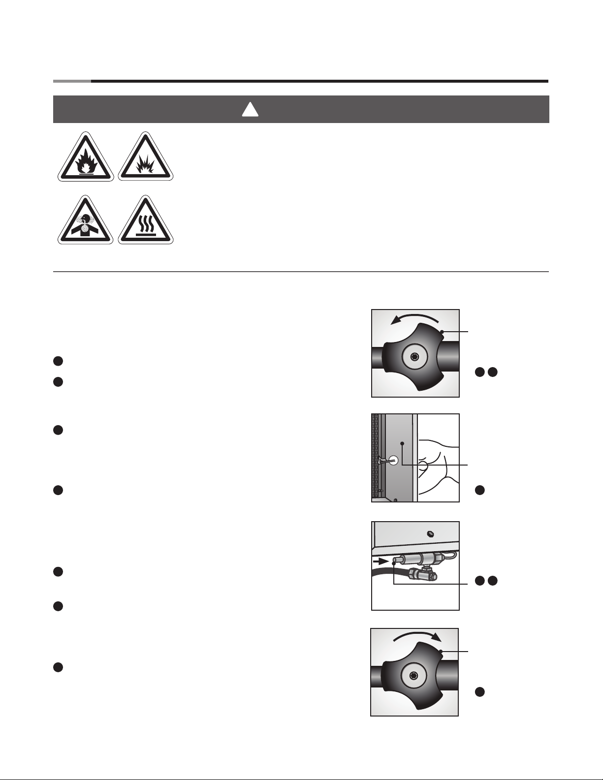
Lighting the Heater:
3.0 Operation • Lighting the Heater • Shutdown
WARNING
IMPORTANT! Inspect the heater before each use (refer to
section 4.0 Maintenance). Operate on a stable, level surface.
Do not knock or tip the heater over while in operation.
1
Open LP gas cylinder (counterclockwise). Figure 3.1.
2
Check all gas connections for leaks using a soap and
water solution. Do not use an open flame to check the
connection.
3
Light and place a match on the ceramic burner through the
hole provided on side of reflector. Do not light the heater
at the orifice or attempt to light with a spark lighter.
Figure 3.2.
4
Depress the brass button on the heater’s safety gas valve
and continue to hold during ignition sequence. The heater
should light within 10 seconds. Figure 3.3.
NOTE: If the heater does not light within 10 seconds, wait
5 minutes before attempting to re-light.
5
If lit, continue to depress the brass button for approximately
30 seconds and then release.
Figure 3.1
Turn handle,
open gas valve.
1 2
Figure 3.2
Light match, insert
through hole that
is located on the
lower side of the
reflector.
3
Figure 3.3
Depress button,
ignite heater.
4 5
6
If the heater flame extinguishes, wait five minutes and
repeat steps 1 through 5.
Shutdown:
7
Close LP gas cylinder (clockwise). Figure 3.4.
Figure 3.4
Turn handle,
close gas valve.
7
9
Page 10
11
4.0 Maintenance • Storage • Troubleshooting Guide
PT Series
4.0 Maintenance
!
WARNING
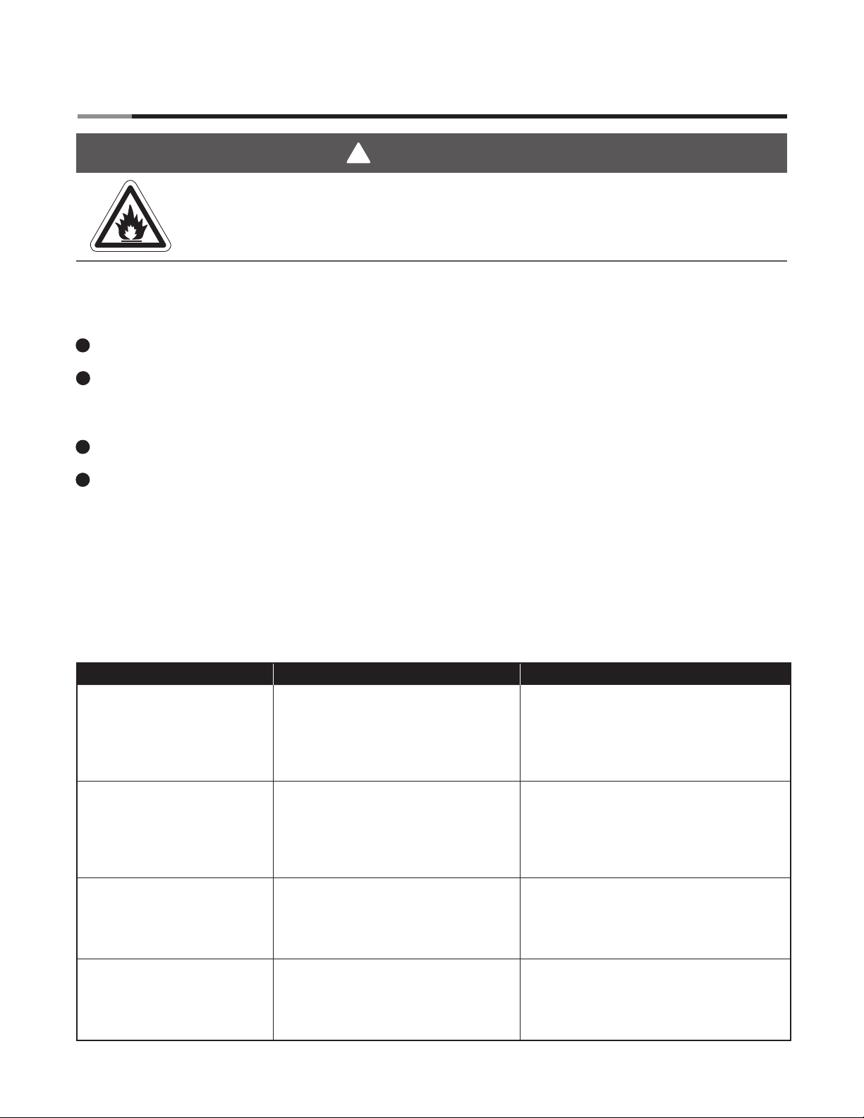
Gas hoses that are cut or have abrasions and/or wear may fail and release gas
resulting in fire, explosion, serious injury or death. Replace worn or damaged hoses
before use.
Never operate the heater if repairs are necessary. If the heater has not been in service for an extended
period of time, the following maintenance procedures should be performed before heater operation:
1
Inspect unit before each use and at least annually by a qualified service person.
2
Using an air hose from 3-5ft. away, gently blow off any dust or dirt that has accumulated on the heater
ceramics (do not exceed 30 psi, vacuuming is acceptable) and venturi tube.
NOTE: If the venturi tube still appears dirty, remove the orifice bracket and clean it with a brush.
3
Clean orifice spud using a soft circular object (toothpick, pipe cleaner).
Wipe the reflector clean using a soap and water solution or a non-abrasive aluminum cleaner.
4
Store LP gas cylinder in accordance with Chapter 5 of the Standard for the Storage and Handling of
Liquefied Petroleum Gases, ANSI/NFPA 58 and all applicable codes. If the heater is not to be used for
an extended period of time, store it in the original carton or a sealed polyethylene bag. When storing
the heater indoors, disconnect the LP gas supply cylinder and remove the cylinder from the heater.
Chart 4.1 • Troubleshooting Guide
Symptom Possible Cause Corrective Action
Heater fails to light. • Cylinder gas valve closed.
• Cylinder overfilled.
• Excessive draft.
• Inadequate gas pressure.
• Heater safety gas valve defective.
• Obstruction in orifice spud.
Heater lights - flame
extinguishes when releasing
the brass button on the
safety gas valve (NOTE: after
depressing the button for one
minute).
Fuel mixture burning within
rayhead assembly.
Ceramic temperature is below
1700° F (NOTE: no orange
glow during operation).
• Inadequate gas pressure.
• Insufficient fuel supply.
• Thermocouple defective or loose.
• Heater safety gas valve defective.
• Gas connection loose.
• Inlet pressure too high.
• Cracked or broken ceramic.
• Improperly lighting.
• Orifice spud misaligned.
• Obstruction in orifice spud.
• Inadequate gas pressure.
• Cylinder gas valve not fully open.
• Kinked or obstructed gas supply line.
• Open valve.
• See safety warning, page 6.
• Relocate or reposition heater.
• Check gas pressure. See Chart 2.2.
• Replace faulty valve.
• Clean or replace orifice.
• Check gas pressure. See Chart 2.2.
• Provide adequate fuel supply.
• Replace or tighten connection into valve.
• Replace faulty valve.
• Tighten and check for leaks.
• Reduce to proper range. See Chart 2.2.
• Replace rayhead assembly.
• Light at ceramic burner element, not at
the orifice (see Section 3.0).
• Replace orifice bracket.
• Clean or replace.
• Check gas pressure, See Chart 2.2.
• Open cylinder gas valve completely.
• Straighten or clean.
10
Page 11
PT Series
5.0 Parts
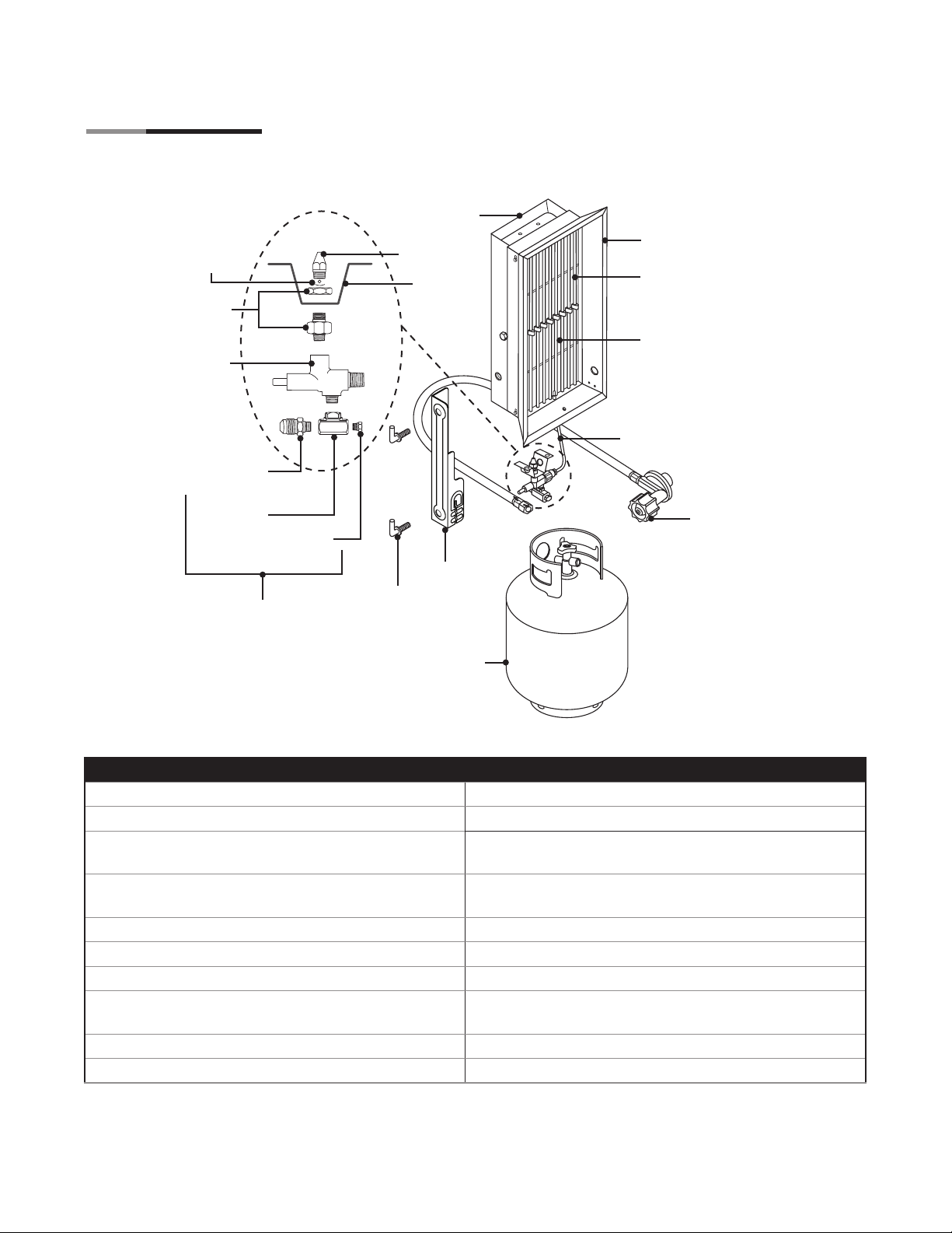
Figure 5.1 • Components
Ball check
& screen
110B
112B
3/8” Male
Connector
3/8” Tee
3/8” Flare
113A
Plug
107, 108
109P, 110P
111
118
119
5.0 Parts • Components List
105, 106
102, 104
101, 103
114B
123A
LP Gas
LP gas cylinder
(not included)
PART# DESCRIPTION PART# DESCRIPTION
P-101 Rayhead assembly for P-16T (Less Rods) P-110B Orifice fittings
P-102 Rods for P-16T (Qty. 9) P-111 Heater orifice spud mounting bracket
P-103 Rayhead assembly for P-32T (Less Rods) P-112B Brass button manual safety gas valve - 1/8”
MPT X 1/8” FPT (mates w/ P-113A)
P-104 Rods for P-32T (Qty. 9) P-113A 90° flared tube fitting - 3/8” O.D. X 1/8” FPT X
1/8” NPT
P-105 Reflector assembly for P-16T P-114B Thermocouple w/ mounting clip for P-112B
P-106 Reflector assembly for P-32T P-118 Cylinder mounting bracket
P-107 Outer heater casing for P-16T P-119 Thumb screw with shoulder 3/8-16 (Qty. 2)
P-108 Outer heater casing for P-32T P-123A 24” hose and regulator assembly
w/ Type-1 inlet
P-109P Propane orifice spud for P-16T P-125 LP gas valve, assembled w/ all fittings for P-32T
P-110P Propane orifice spud for P-32T P-126 LP gas valve, assembled w/ all fittings for P-16T
Visit www.detroitradiant.com/parts for additional replacement parts information.
11
Page 12

6.0 Repair • 7.0 Maintenance
PT Series
6.0 Repair
This heater is covered by a limited warranty (see Section 7.0 Limited Warranty). Detroit Radiant Products
also offers repair services for the following condition:
Symptom: No orange glow on ceramic surface (and/or abnormal noise) during operating.
Possible Cause: Cracked ceramics, loose ceramics, missing gasket material or other physical abuses
resulting in the fuel mixture burning within the rayhead assembly (behind ceramic surface).
Immediate Action: Turn the off heater.
Corrective Action: Replace the rayhead assembly or return it to Detroit Radiant Products for repair.
Repair cost is $48.00 for each P-16T model and $55.00 for each P-32T model. Repair charges include
return shipping and handling costs. Units can be returned COD via UPS (additional fees for COD service
will apply).
The preferred method of payment is credit card (Visa, MasterCard or Discover). Include a valid credit
card number along with name on card and expiration date. The alternate payment method is personal
check. Please make check payable to Detroit Radiant Products Company for the repair cost amount
above.
DO NOT include the mounting accessories (tank, hose, bracket, regulator, etc.). Be sure to enclose the
heater (packaged tightly), payment information, the return address and a contact phone number. If your
heater requires work in addition to burner reconstruction, you will be contacted with a quote. Lead-time is
2-5 working days. Heater returns should be addressed to:
Repair Department
c/o Detroit Radiant Products Co.
21400 Hoover Rd.
Warren, MI 48089
Please call 800-222-1100 with questions.
7.0 Limited Warranty
Heater models P-16T and P-32T are warranted by Detroit Radiant Products Co. to the original user
against defects in workmanship or materials under use for 90 days after date of purchase. The company’s
sole obligation under this warranty is limited to furnishing replacement parts, FOB Warren, Michigan for
any parts which the company’s examination discloses to its satisfaction to be defective. Defective parts
are to be returned to the company, transportation charges prepaid. The company’s liability for
consequential and incidental damages is expressly disclaimed.
© 2012 Detroit Radiant Products Company
21400 Hoover Road Warren, MI 48089 U.S.A.
Voice: (586) 756-0950
Fax: (586) 756-2626
Website: www.detroitradiant.com
12
 Loading...