

Page 1
DX2 Series
!
Insert Manual
For complete installation instructions, reference the Tube Heater General Manual that
accompanies this insert manual.
The DX2 Series Infra-Red Tube Heater is a positive pressure, single-stage radiant heater system. This
insert manual is a supplement to the Tube Heater General Manual and provides specic information
related to the DX2 Series model. All persons involved with the installation, operation and maintenance of
the heater system must read and understand the information in this insert manual and the accompanying
Tube Heater General Manual.
For Your Safety
If you smell gas:
WARNING
Improper installation, adjustment, alteration, service or maintenance can cause
property damage, injury or death. Read the installation, operation and maintenance
instructions thoroughly before installing or servicing this equipment.
This heater must be installed and serviced by trained gas installation and service
personnel only. Failure to comply could result in personal injury, asphyxiation, death,
re or property damage.
In locations used for the storage of combustible materials, signs must be posted to
specify the maximum permissible stacking height to maintain the required clearances
from the heater to the combustibles. Signs must either be posted adjacent to the
heater thermostats or in the absence of such thermostats, in a conspicuous location.
Not for residential use! Do not use this heater in the home, sleeping quarters,
attached garages, etc. Installation of a commercial tube heater system in residential
indoor spaces may result in property damage, serious injury, asphyxiation or death.
• Do not try to light any appliance. • Immediately call your gas supplier from a neighbor’s phone.
• Do not touch any electrical switch. • Follow the gas supplier’s instructions.
• Do not use any phone in your building. • If you cannot reach your gas supplier, call the re department.
Keep these instructions for future reference.
LIODX2a- Rev. 18111
2M-9/09_r3-5/14(DRP)
Replaces: LIODX2a-1M-3/09(CDS)
Page 2

DX2 Series
Contents
1.0 Safety...................................................................3
Safety Labels and Locations ............................................3
Clearance to Combustibles .............................................4
2.0 Installation . . . . . . . . . . . . . . . . . . . . . . . . . . . . . . . . . . . . . . . . . . . . . . . . . . . . . . . . . . . . . . 6
Gas Requirements....................................................6
Electrical Requirements................................................6
Wiring . . . . . . . . . . . . . . . . . . . . . . . . . . . . . . . . . . . . . . . . . . . . . . . . . . . . . . . . . . . . . 7
Specications ......................................................10
Tube Installation Sequence ............................................11
3.0 Operation ..............................................................12
Sequence of Operation ...............................................12
Thermostat . . . . . . . . . . . . . . . . . . . . . . . . . . . . . . . . . . . . . . . . . . . . . . . . . . . . . . . . 12
Operational Indicator Lights............................................13
4.0 Troubleshooting Guide ...................................................14
5.0 Parts ..................................................................18
Components . . . . . . . . . . . . . . . . . . . . . . . . . . . . . . . . . . . . . . . . . . . . . . . . . . . . . . . 18
Parts List ..........................................................18
Kit Contents Check List ...............................................20
Approvals..........................................................20
Limited Warranty ....................................................20
NOTE: See page 10 for a list of available models and specications.
2
Page 3
Air Metering Orifice
DO NOT REMOVE
TP-114
TP-3014
3”
DX2 Series
SAMPLE
1.0 Safety • Safety Labels and Locations
1.0 Safety
Read and understand all safety information and warnings in this insert manual and the
Tube Heater General Manual before installation, operation and maintenance of the
radiant tube heater system.
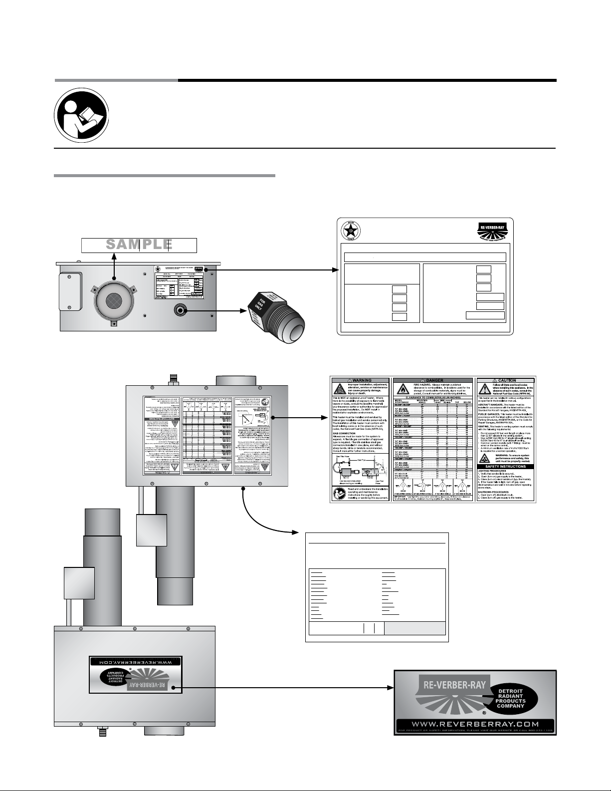
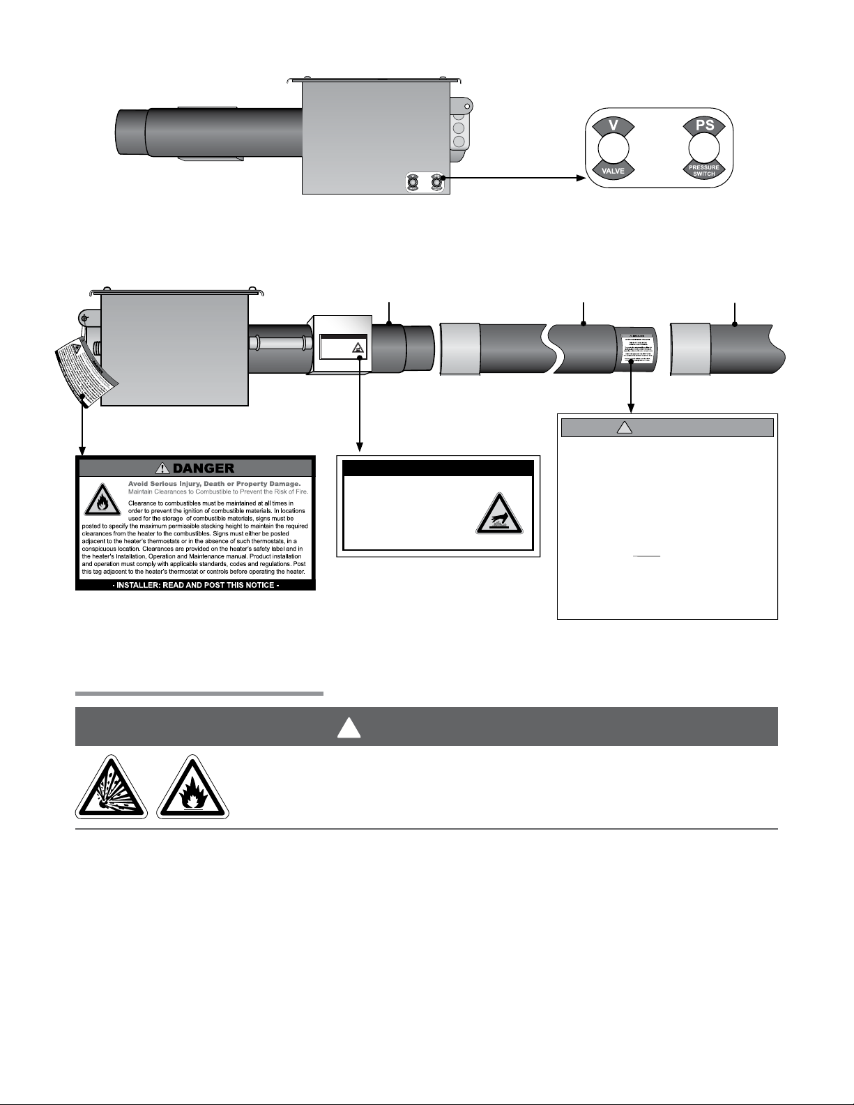
Safety Labels and Their Locations
Product safety signs or labels should be replaced by the product user when they no longer are legible.
Contact either your local distributor or the product manufacturer for obtaining replacement signs or labels.
Back Panel
Top Panel
F/N: LLAC
Air Metering Orice
F/N: LLTB018 (Natural Gas)
F/N: LLTB019 (LP Gas)
RE-VERBER-RAY INFRA-RED RADIANT TUBE HEATER
FOR INDOOR INSTALLATION ONLY
MODEL NO.
DX
HL2 - 40 - 125N
DESIGN COMPLIES WITH:
ANS Z83.20b-2003-GAS FIRED LOW INTENSITY INFRA-RED HTR.
VOLTS AC 60Hz
AMPS - Starting
AMPS - Running
Heater Type:
DETROIT RADIANT PRODUCTS CO.
21400 HOOVER ROAD - WARREN, MI 48089
(586) 756-0950 www.reverberray.com
INPUT BTU/H
125,000 / 95,000
125,000
Manifold Pressure
Max. Inlet Pressure
120V
4.8
1.1
C1
Min. Inlet Pressure for
SAMPLE
Purpose of Input Adjustment
Min. Mounting Angle
Max. Mounting Angle
Combustion Chamber
F/N: LLTCL001 Clearance to
DX240125N
DX2-125
Production Code:
5.05
Version:
Data on this label is for the model shown on this label. If your heater has been converted,
this information is not accurate. Please contact the factory for assistance.
BURNER COMPONENTS:
Gas Valve:
Circuit Board:
Wire Harness:
N.O. Switch:
N.O. VL Orice:
N.C. Switch:
N.C. VL Orice:
Di Switch:
Di VL Orice:
Igniter:
Burner:
16” Tube:
Ind. Lights:
HEATER
TYPE:
C1
For parts replacement information, contact factory at 586-756-0950 or visit www.drp-co.com/parts.
(Specify TP-#’s)
VR4205-1324
240
MARK10DX-117
351A
3 PCS Harness
352A
None
N/A
None
None
N/A
None
IS22010051F5166
264E
Grey (+ / -)
SAMPLE
Norton
50
Mid
201B
4” Gen.
380
Yellow - 120V
328
C1 C2 C3
Orice Type:
Gas:
19
TP-204#
Air:
1 5/16”
TP-44#191 7/16”
Serial No.: 0804XXXXXXXXXX 0001
Stock:
Add-On:
Diag. Light:
Term. Block:
Transformer:
Fan:
Alt. Fan:
Alt. Fan Usage:
Relay:
Filter:
24 Volt In:
120 Volt In:
Gas In:
Extra VL Orice:
Internal Use Only:
Electric:
19
LLWT038
Tag:
1 5/16”
None
None
N/A
On Circuit Board
None
40 VA
Fasco Lg.
50Hz - 120V
When Specified
None
None
3 T-plug
2 x 4 Box
7/8” FC Flare
None
Special 1:
Special 2:
FOR USE WITH
NAT GAS
3.5in.
W.C.P.
W.C.P.
14.0in.
W.C.P.5.0in.
0 DEGREES
45 DEGREES
4” BC Aluminized
For Stainless Steel Upgrades the Combustion Table is upgraded to 409 Stainless Steel
Serial No. 0603DETR12345 0001
Combustibles Label.
N/A
N/A
55A
55B
N/A
N/A
832
66
Burner Control Box
83
Component Label
(located under the top
17
1 7/16”
panel)
Rating
Plate
F/N: LLLOGO1
Bottom Panel
3
Page 4
!
1.0 Safety • Safety Labels and Locations • Clearance to Combustibles
DX2 Series
Right Panel
(Valve Compartment)
F/N: LL01 - Clearance Safety Tag
(Afx adjacent to heater’s thermostat)
Left Panel
(Fan Compartment)
16” Burner Tube
SERVICE ACCESS PANEL
IGNITER & FLAME SENSE COMPARTMENT
1. Turn off gas & electricity.
2. Remove cover by lifting top
cover upward and outward.
CAUTION: HOT SURFACE.
KEEP COVER IN PLACE. REMOVE FOR SERVICE ONLY.
SERVICE ACCESS PANEL
IGNITER & FLAME SENSE COMPARTMENT
1. Turn off gas & electricity.
2. Remove cover by lifting top
cover upward and outward.
CAUTION: HOT SURFACE.
KEEP COVER IN PLACE. REMOVE FOR SERVICE ONLY.
F/ N: L LTB 0 26
F/ N: LLV3 EP6
Primary Combustion
Chamber
!
INSTALLER
AVOID EQUIPMENT FAILURE
THIS 10 FT. TUBE IS THE
COMBUSTION CHAMBER.
The combustion chamber utilizes either 409
stainless, titanium alloy or aluminized steel -
depending on the model number of your heater.
THIS TUBE MUST BE THE FIRST TUBE
FOLLOWING THE BURNER CONTROL BOX.
Rotate the tube’s welded seam to bottom.
Consult the manual(s) for further details.
F/N: LLTB004 (orange)
Radiant
Tube(s)
Clearance to Combustibles
WARNING
Placement of explosive objects, ammable objects, liquids and vapors close to
the heater may result in explosion, re, property damage, serious injury or death.
Do not store or use explosive objects, liquids or vapor in the vicinity of the heater.
Clearance to combustibles is dened as the minimum distance that must exist between the tube surface,
or reector, and any combustible items (see Figure 1.1). It also pertains to the distance that must be
maintained from moving objects around the tube heater.
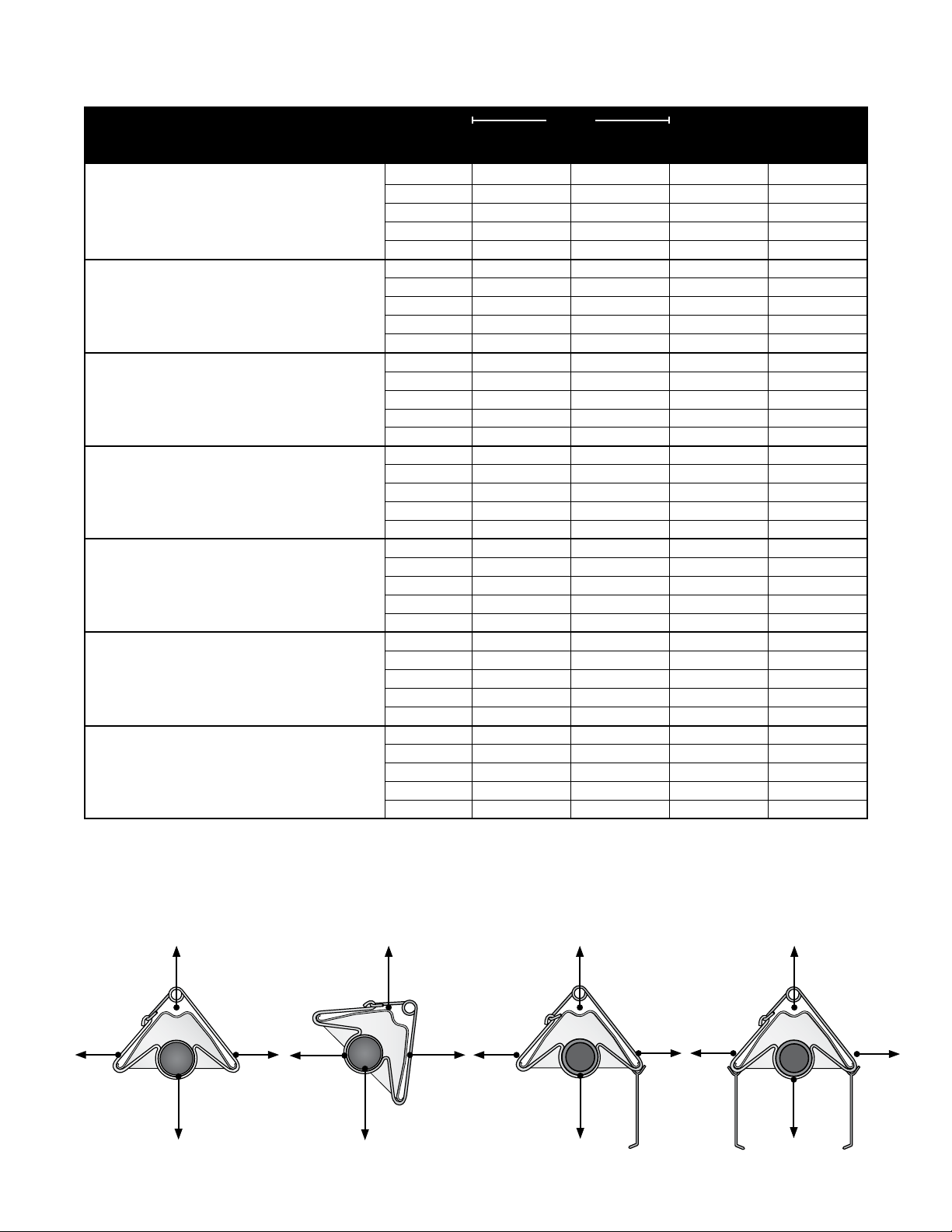
When installing the tube heater system, clearances to combustibles for your series tube heater and
conguration must be maintained. Refer to Chart 1.1 on the following page to determine the required
distances for your model.
The stated clearance to combustibles represents a surface temperature of 90ºF (32ºC) above room
temperature. Building materials with a low heat tolerance (such as plastics, vinyl siding, canvas,
tri-ply, etc.) may be subject to degradation at lower temperatures. It is the installer’s responsibility to
assure that adjacent materials are protected from degradation.
4
Page 5
DX2 Series
1.0 Safety • Clearance to Combustibles
Chart 1.1 • Clearance to Combustibles in Inches (see Figure 1.1 for Mounting Angles)
Mounting
Model Number
DX2 (20, 30, 40) - 50, 60 [N, P]
with 1 side shield
with 2 side shields 0° 9 9 6 47
20 ft. from burner 0° 7 7 6 30
DX2 (20, 30, 40) - 75 [N, P] 0° 9 9 6 60
with 1 side shield 0° 29 8 6 60
with 2 side shields 0° 9 9 6 60
20 ft. from burner
DX2 (20, 30, 40, 50) - (80, 96, 100) [N, P] 0° 14 14 6 66
with 1 side shield 0° 29 8 6 66
with 2 side shields 0° 16 16 6 66
20 ft. from burner 0° 7 7 6 30
DX2 (30, 40, 50, 60) - 125 [N, P] 0° 20 20 6 76
with 1 side shield 0° 42 8 6 76
with 2 side shields 0° 20 20 6 76
20 ft. from burner 0° 7 7 6 30
DX2 (40, 50, 60) - 150 [N, P] 0° 24 24 6 81
with 1 side shield 0° 42 8 6 81
with 2 side shields 0° 23 23 6 81
20 ft. from burner 0° 11 11 6 44
DX2 (40, 50, 60, 70) - 175 [N, P]
with 1 side shield 0° 50 8 6 92
with 2 side shields 0° 30 30 6 92
20 ft. from burner 0° 11 11 6 44
DX2 (50, 60, 70, 80) - 200 [N, P] 0° 41 41 6 94
with 1 side shield 0° 54 8 6 94
with 2 side shields 0° 30 30 6 94
20 ft. from burner 0° 11 11 6 44
Angle*
0° 9 9 6 47
45° 39 8 10 47
0° 29 8 6 47
45° 39 8 10 60
0° 7 7 6 30
45° 39 8 10 66
45° 58 8 10 76
45° 58 8 10 81
0° 34 34 6 92
45° 63 8 10 92
45° 63 8 10 94
Side
Top BelowFront Behind
Heaters mounted on an angle between 0° to 45° must maintain clearances posted for 0° or 45°; whichever is greater.
*
Figure 1.1 • Mounting Angles
0° Mounting Angle 45° Mounting Angle
Top
Side
Side
Below
Front
Below
Top
Behind
0° Mounting Angle
with 1 Side Shield
(P/N: SSE)
Top
Front Behind
Below
0° Mounting Angle
with 2 Side Shields
(P/N: SSE)
Top
Side Side
Below
5
Page 6
2.0 Installation • Gas Requirements • Electrical Requirements
!
2.0 Installation
WARNING
Improper installation, adjustment, alteration, service or maintenance can cause property
damage, serious injury or death. Read and understand, the installation, operating and
maintenance instructions thoroughly before installing or servicing this equipment. Only
trained, qualied gas installation and service personnel may install or service this equipment.
Not for residential use! Do not use this heater in the home, sleeping quarters, attached
garages, etc. Installation of a commercial tube heater system in residential indoor spaces
may result in property damage, serious injury or death.
Instructions for the following are detailed in the Tube Heater General Manual:
• Design considerations
• Hanger suspension and placement
• Tube layout and assembly
• Burner control box suspension
• Reectors (and accessories)
• Venting and combustion air intake
• Gas requirements
• Bafe assembly
DX2 Series
Note: Electronic versions of all manuals are available at www.detroitradiant.com
Gas Requirements
Type of Gas
Natural 3.5 Inches W.C. 5.0 Inches W.C. 14.0 Inches W.C.
Liqueed Petroleum 10.0 Inches W.C. 11. 0 Inches W.C. 14.0 Inches W.C.
IMPORTANT: Consult the Tube Heater General Manual for gas connection requirements.
Required Manifold
Pressure
Minimum Inlet
Pressure
Maximum Inlet
Pressure
Electrical Requirements
NOTICE
The DX2 Series comes standard requiring a 120VAC connection to the thermostat. An optional 24VAC
internal relay (24VAO) may be factory installed if the heater is to be controlled via a 24VAC thermostat.
A 40VA transformer is necessary when using the 24VAO option.
NOTE: A relay transformer may be used in lieu of the factory installed 24VAO option.
• 120VAC - 60 Hz GRD, 3-wire.
• 120VAC thermostat connection.
• Starting current 4.8 amps
• Running current 1.1 amps
6
Page 7
!
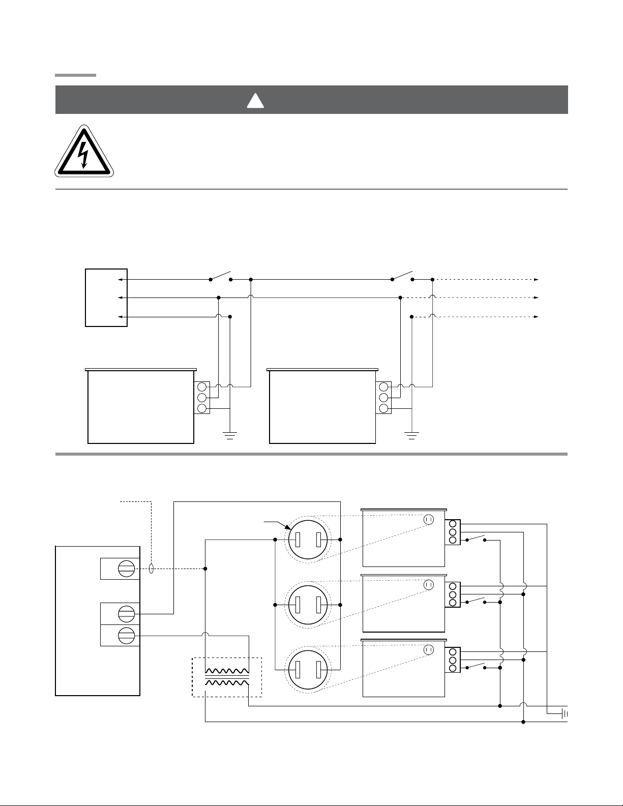
120VAC-60 Hz.
Supply
NOTE: Up to 4 line voltage tube heaters can
be wired to most thermostats.
L1
Neutral
Ground
Heaters on the same vent must
share the same thermostat.
Additional heaters
Burner BoxBurner Box
DX2 Series
Common required
Common required
Wiring
Electric Shock
Field wiring to the tube heater must be connected and grounded in accordance with national,
state, provincial, local codes and to the guidelines in the Tube Heater General Manual and
Series Insert Manual. In the United States refer to the most current revisions to the ANSI/NFPA
70 Standard and in Canada refer to the most current revisions to the CSA C22.1 Part I Standard.
Figure 2.1 • Field Wiring Diagrams
A. 120VAC Single/Multiple Line Voltage Heater(s)
2.0 Installation • Wiring
WARNING
B. 24VAO (Internal Relay Option)
for thermostats
for thermostats
that require
that require
constant power.
constant power.
Common
W
R
24VAC Digital
Thermostat
1/4” spade terminals
required (as supplied)
24VAC
120 VAC
External
Transformer
(field suppied)
COM
24V
COM
24V
Burner Control
Box w/ 24VAO
Burner Control
Box w/ 24VAO
24V
COM
Burner Control
Box w/ 24VAO
120 Volt Power
(Observe polarity)
L1
N
7
Page 8
2.0 Installation • Wiring
120VA
N
O
Igniter
N
120VACL1
DX2 Series
Before eld wiring this appliance - Check existing wiring; replace if necessary.
Note: If any of the original wire supplied with the appliance must be replaced, it must be replaced with
wiring material having a temperature rating of at least 105° C.
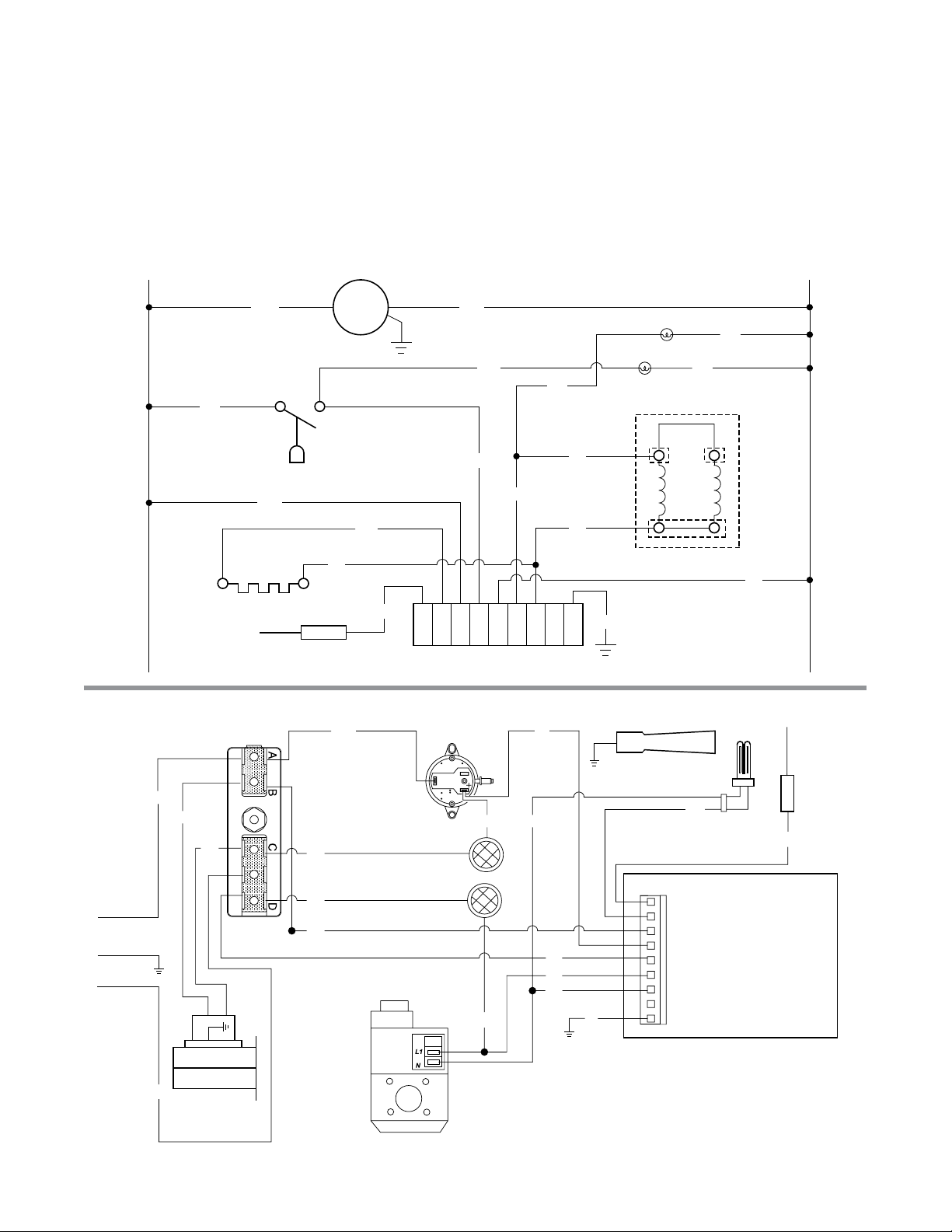
Figure 2.2 • Internal Wiring Diagrams
A. Ladder Diagram - TP-351A
BK
BK
BK
Igniter
B. Block Diagram - TP-351A
Terminal Block
Pressure Switch
Flame Rod
Blower
W
BK
BK
BR
SIC1
PROBE
BK
BK
O
R
LINE1
TH
NEUT
VALVE
Ignition Module
BK
NEUT
BK
Indicator Lights
BK
Gas Valve
BK
W
W
G
GND
Flame
Rod
Burner
BK
BK
L1
C
W
BK
Blower
Pressure Switch
BK
Indicator Lights
BK
BK
Gas Valve
BK
W
W
R
W
BK
G
BK
Probe
SIC1
Line1
TH
Neutral
Valve
Neutral
Ground
BR
Ignition Module
8
Page 9
N
Relay
Burner
DX2 Series
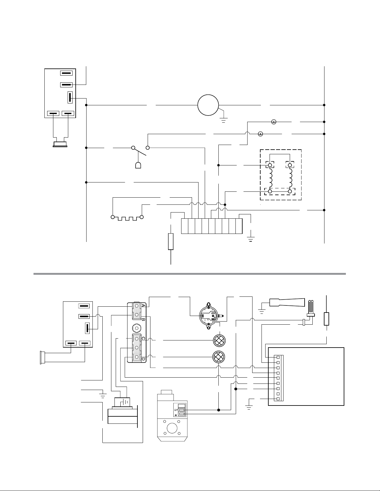
Figure 2.3 • Alternative Wiring Diagrams
A. TP-351A Ladder Diagram - Internal Relay Option (24VAO)
120VACL1
NC
NO
2.0 Installation • Wiring
COM
24VAC
Thermostat
Te rminal
BK
BK
Igniter
BK
Pressure Switch
BK
W
BR
Blower
BK
O
R
LINE1
TH
SIC1
PROBE
NEUT
IGNITION MODULE
BK
Indicator Lights
BK
BK
BK
Gas Valve
BK
W
W
G
NEUT
VALVE
GND
B. TP-351A Block Diagram - Internal Relay Option (24VAO)
BK
Pressure Switch
BK
Indicator Lights
BK
BK
Gas Valve
Thermostat
Te rminal
24VAC
Relay
120VAC
NO NC
COM
L1
N
W
Te rminal Block
BK
BK
Blower
BK
BK
W
O
W
R
W
G
Probe
SIC1
Line1
TH
Neutral
Valve
Neutral
Ground
Igniter
BK
Flame
Rod
BR
Ignition Module
9
Page 10
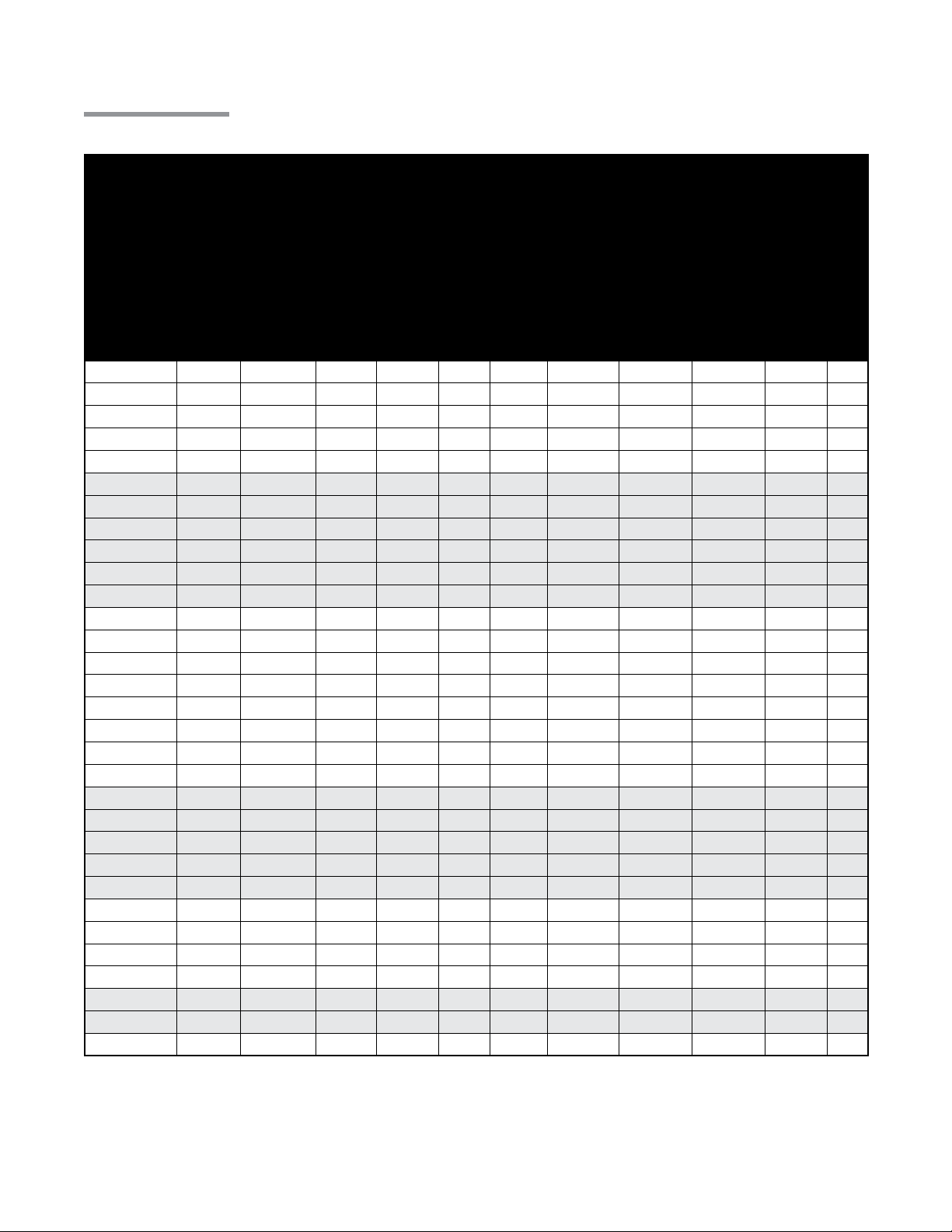
2.0 Installation • Product Specications
Specifications
Chart 2.1 • Specications
DX2 Series
Model Number
DX2-20- 50 N or LP 50,000 21’-8” 13’- 0” 120 N/A 9’ to 15’ Alum Alum 20.2 5
DX2-20- 60 N or LP 60,000 21’-8” 13’- 0” 120 N/A 10’ to 15’ Alum Alum 20.2 5
DX2-20-75 N or LP 75,000 21’-8” 13’-0” 120 145 11’ to 18’ Alum Alum 20.2 5
DX2-20- 80 N or LP 80,000 21’-8” 13’-0” 120 145 11’ to 18’ Alum Alum 20.2 5
DX2-20-96 N or LP 96,000 21’-8” 13’- 0” 120 145 12’ to 20’ Alum Alum 20.2 5
DX2-30-50 N or LP 50,000 31’- 4” **17’-8” 160 N/A 10’ to 15’ Alum Alum 30.4 4
DX2-30-60 N or LP 65,000 31’-4” **17’-8” 160 N/A 11’ to 18’ Alum Alum 30.4 4
DX2-30-75 N or LP 75,000 31’-4” **17’-8” 160 195 12’ to 20’ Alum Alum 30.4 4
DX2-30-80 N or LP 80,000 31’- 4” **17’-8” 160 195 12’ to 20’ Alum Alum 30.4 5
DX2-30-100 N or LP 100,000 31’- 4” **17’-8” 160 195 13’ to 23’ Alum Alum 30.4 5
DX2-30-125 N or LP 125,000 31’-4” **17’-8” 160 195 14’ to 25’ Alum Alum 30.4 5
DX2-40- 50 N or LP 50,000 41’- 0” 22’-8” 190 N/A 11’ to 18’ Alum Alum 40.5 2
DX2-40-60 N or LP 60,000 41’- 0 ” 22’-8” 190 N/A 11’ to 18’ Alum Alum 40.5 2
DX2-40-75 N or LP 75,000 41’- 0” 22’-8” 190 235 12’ to 20’ Alum Alum 40.5 2
DX2-40- 80 N or LP 80,000 41’- 0” 22’-8” 190 235 12’ to 20’ Alum Alum 40.5 5
DX2-40-100 N or LP 100,000 41’- 0 ” 22’-8” 190 235 13’ to 23’ Alum Alum 40.5 4
DX2- 40 -125 N or LP 125,000 41’- 0 ” 22’-8” 190 235 14’ to 25’ Alum Alum 40.5 4
DX2- 40-150 N or LP 150,000 41’- 0 ” 22’-8” 190 235 15’ to 27’ Titan Alum 40.5 4
DX2- 40 -175 N or LP *175,000 41’- 0” 22’-8” 190 N/A 16’ to 30’ Titan Alum 40.5 4
DX2-50-100 N or LP 100,000 50’-8” **27’-4” 235 290 15’ to 27’ Alum Alum 50.6 2
DX2- 50-125 N or LP 125,000 50’-8” **27’-4” 235 290 15’ to 27’ Alum Alum 50.6 4
DX2-50-150 N or LP 150,000 50’-8” **27’- 4” 235 290 16’ to 30’ Titan Alum 50.6 4
DX2-50 -175 N or LP *175,000 50’- 8” **27’- 4” 235 N/A 17’ to 35’ Titan Alum 50.6 2
DX2-50-200 N or LP *200,000 50’-8” **27’-4” 235 N/A 18’ to 40’ Titan Alum 50.6 2
DX2- 60-125 N or LP 125,000 60’- 4” 32’- 4” 265 330 16’ to 30’ Alum Alum 60.7 2
DX2- 60 -150 N or LP 150,000 60’- 4” 32’- 4” 265 330 17’ to 35’ Titan Alum 60.7 2
DX2- 6 0 -175 N orLP *175,000 60’- 4” 32’- 4” 265 N/A 17’ to 35’ Titan Alum 60.7 2
DX2-60-200 N or LP *200,000 60’- 4” 32’- 4” 265 N/A 18’ to 40’ Titan Alum 60.7 2
DX2-70-175 N or LP *175,000 70’-0” **37’-2” 300 N/A 19’ to 42’ Titan Alum 70.9 2
DX2-70-200 N or LP *200,000 70’-0” **37’-2” 300 N/A 19’ to 42’ Titan Alum 70.9 2
DX2-80-200 N or LP *200,000 79’-8” 42’-0” 330 N/A 20’ to 45’ Titan Alum 81.0
* Model requires stainless steel tube clamp (P/N: TP-220) to be located at the seam between the primary
combustion chamber and the secondary combustion tube downstream of the burner control box.
** Model requires 5EA-SUB accessory package when installing in a U-shaped conguration (P/N: TF1B).
Titan = Coated titanium treated steel.
Alum = Coated aluminized treated steel.
Gas Type (Select One)
BTU/H
Straight Length (Dim A)
U-Tube Length (Dim. B)
Weight (lbs.)
Stainless Steel Weight
(lbs.)
Recommend
Mounting Height
Combustion Chamber
(Black Coated)
Radiant Emitter Tube(s)
(Black Coated)
Radiant Surface Area
(sq. ft.)
36” Bafe Sections
2
10
Page 11
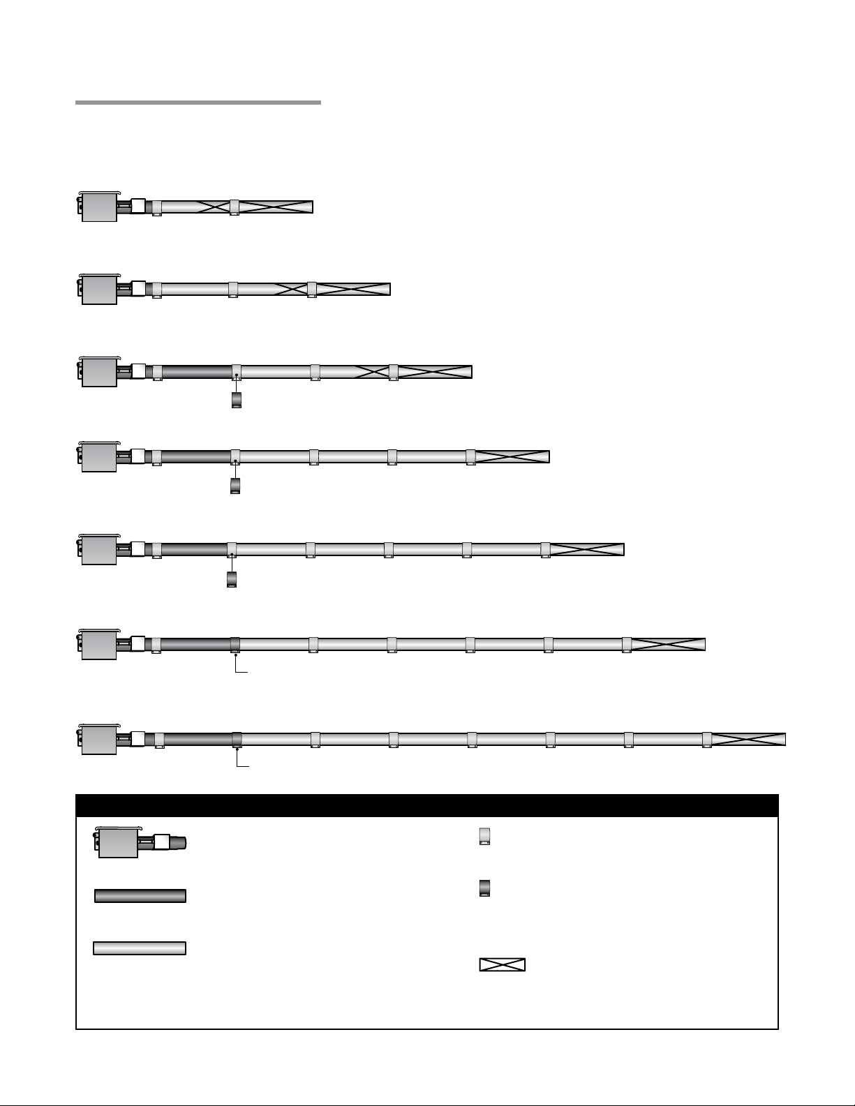
DX2 Series
2.0 Installation • Tube Sequence • Heater Length
Tube Installation Sequence
Figure 2.4 • Tube Installation Sequence
Important! The combustion chamber & radiant tube sections must be installed in the following order.
20 Foot
30 Foot
40 Foot
Stainless Steel Clamp on 175 MBH models (P/N: TP-220).
50 Foot
60 Foot
70 Foot
80 Foot
Stainless Steel Clamp on 175 - 200 MBH models (P/N: TP-220).
Stainless Steel Clamp on 175 - 200 MBH models (P/N: TP-220).
Stainless Steel Clamp Location (P/N: TP-220).
Stainless Steel Clamp Location (P/N: TP-220).
Key
Burner Control Box with
16” Burner Tube
Black Coated Combustion
Chamber Tube*
Black Coated Aluminized Combustion
Chamber/Radiant Emitter Tube
Standard Tube Clamp
Stainless Steel Tube
Clamp (P/N: TP-220)
175-200 MBH models only - Located
between 1st and 2nd 10 ft. tube sections.
Bafe Location
*Aluminized steel (50,000 to 125,000 BTU/H models), Titanium stabilized aluminized steel (150,000 to 200,000
models). NOTE: Refer to the Tube Heater General Manual, Chart 3.6 (page 23) for secured reector joints.
11
Page 12
!
3.0 DX2 Series Operation • Sequence of Operation • Thermostat • Diagnostics
DX2 Series
3.0 Operation
WARNING
This heater must be installed and serviced by trained gas installation and service
personnel only.
Do not bypass any safety features or the heater’s built in safety mechanisms will be
compromised.
Note: Reference the Tube Heater General Manual for installation requirements.
Sequence of Operation
Starting Circuit: Upon a call for heat, the fan is energized. Once operational static pressure is achieved,
the differential switch will close initiating the ignition sequence. After a 5-second delay, the Glo-bar™
is energized for 45 seconds and the control allows the gas valve to open.
The trial for ignition is 8 seconds. If ame sense is not established within 8.5 seconds, the heater will
attempt two (2) additional ignition sequences before proceeding to soft lockout. Soft lockout
automatically retries after one (1) hour or the control can be reset by briey interrupting the power
source.
Running Circuit: After ignition, the ame rod monitors burner ame. If sense of ame is lost, the control
immediately acts to reignite the gas-air mixture (identical to the starting sequence). If ame sense is
not established within 8.5 seconds, the heater will attempt two (2) additional ignition sequences
before proceeding to soft lockout. The control can be reset by briey interrupting the power source.
Thermostat
NOTE: Different thermostats operate according to their particular features. Refer to thermostat
specications for details.
The DX2 Series comes standard requiring a 120VAC connection to the thermostat. An optional 24VAC
internal relay (24VAO) may be factory installed if the heater is to be controlled via a 24VAC thermostat.
A 40VA transformer is necessary when using the 24VAO option (Figure 2.1B).
NOTE: A relay transformer may be used in lieu of the factory installed 24VAO option.
12
Page 13
DX2 Series
3.0 Operation • Diagnostics
Operational Indicator Lights
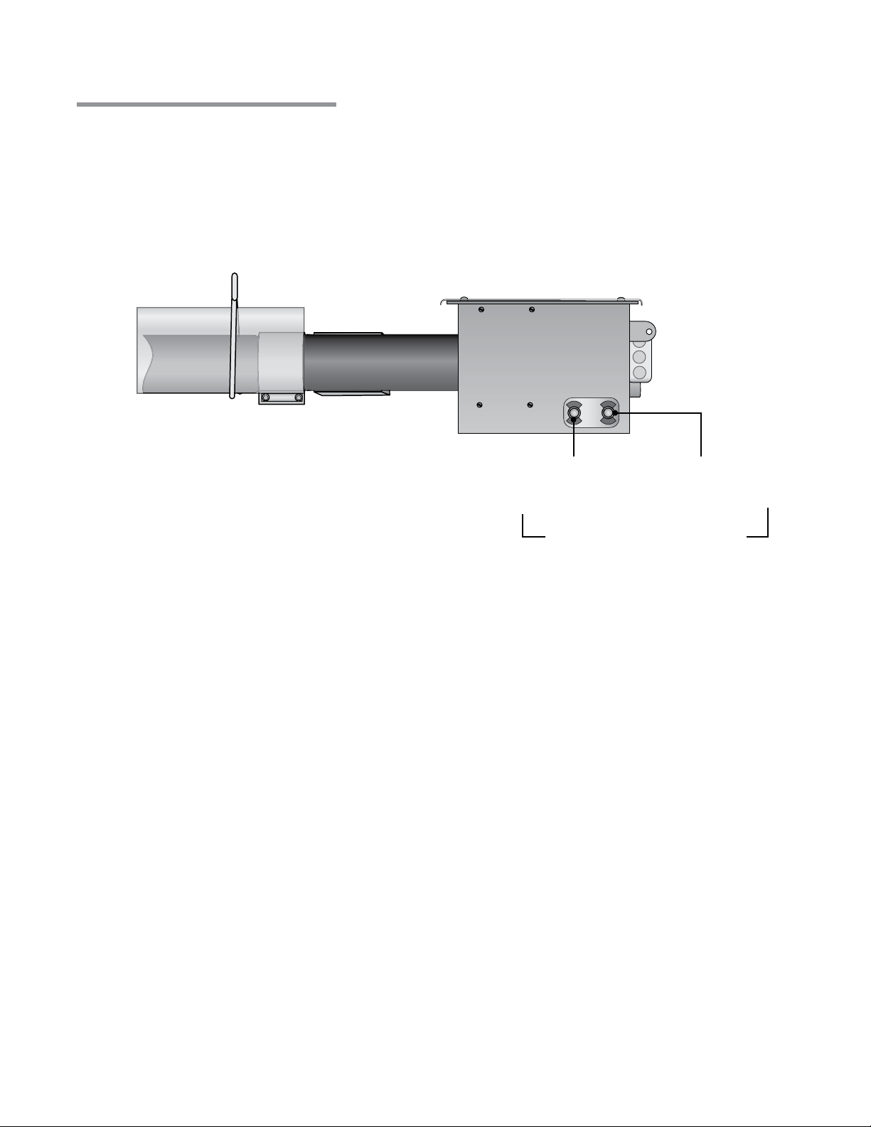
The externally located operational indicator lights are provided to assist in troubleshooting of the heater.
Refer to the following pages for additional troubleshooting.
Figure 3.1 • Operational Indicator Lights
PS
V
PRESSURE
VALVE
SWITCH
Light 1
Indicates Valve
Opens
Light 2
Indicates Pressure
Switch Closes
Operational Indicator Lights
13
Page 14
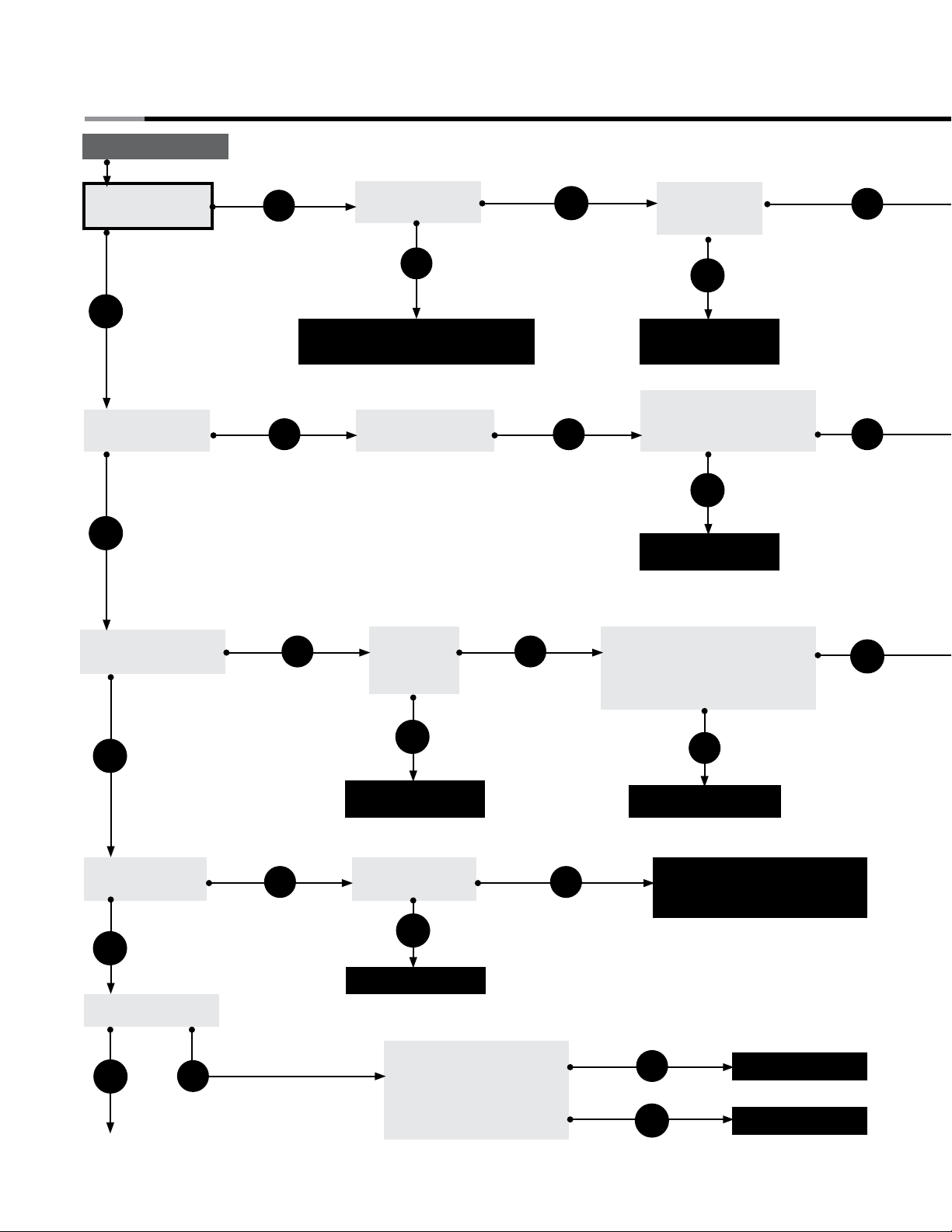
4.0 Troubleshooting Guide
4.0 Troubleshooting Guide
Turn up thermostat
DX2 Series
Does the fan
blower turn on?
Yes
Does the switch
light energize?
Yes
Does the ignitor warm
up and glow red?
No
Is the power at the
heater 120V?
Yes
No
Find the source of the electrical
problem between panel and heater.
No No
No No
Is the light burnt out?
If so, replace.
Is the ignitor
physically
damaged?
Is the blower
obstructed?
Yes
Remove obstruction
and lubricate fan.
Is the inlet or the outlet of
the unit obstructed (i.e.,
ice, birds nest, dirt, etc.)?
Yes
Remove obstruction.
Check voltage at ignitor during
ignition sequence (usually 3045 seconds after power to the
heater). Is it 120V?
No
No
Yes
Yes
Does valve light
energize?
Yes
Does valve open?
Yes
Continued on page 16.
No
No
Yes
Replace ignitor.
Does the burner
ignite at all?
Yes
Replace faulty light.
Confirm that gas pressure
is within minimum and
maximum inputs as
indicated on the burner
rating plate. Are they ok?
14
No
No
Replace circuit board.
The circuit board and/or wiring
harness may be faulty and
needs to be replaced.
No
Yes
Correct problem.
Replace gas valve.
Page 15
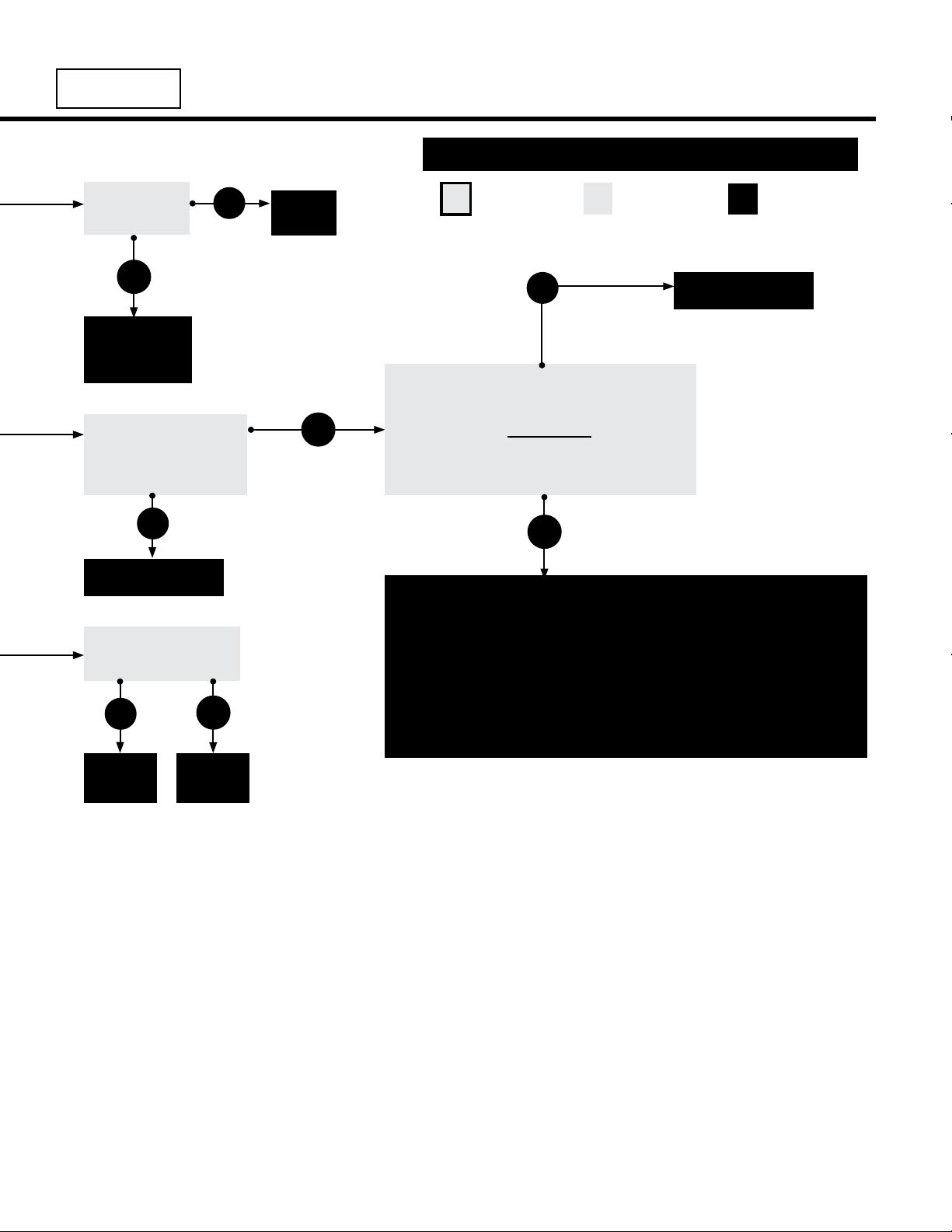
DX2 Series
4.0 Troubleshooting Guide
NOTICE
Is 120V coming
to the fan?
Yes
The fan is faulty
and must be
replaced.
Check for loose wiring
or resistance in hose
connection to pressure
switch. Are they ok?
No
Bypassing any switch is intended for testing purposes only. Do not leave switch bypassed
during normal operation or the heater’s built-in safety mechanisms will be compromised.
Key
No
Correct
wiring.
Yes
Start
Question
No
The heater is equipped with a safety pressure
switch. This differential switch, located in
the valve compartment, is a normally open
pressure switch. Temporarily place jumpers
across the terminals of the switch (Be sure to
reinstall the burner control box cover).
Does the light energize?
Process
Question
Corrective
Action
Replace faulty light.
Yes
Repair.
Is resistance through
the ignitor 50-400 Ω ?
No
Replace
ignitor.
Yes
Consult
factory.
Replace the differential switch after verifying the following:
• Bafe(s) is/are in the radiant tube(s) farthest from the burner.
• The heater, fan blower, squirrel cage, intake and exhaust are free from
dirt and obstructions.
• The 4” air intake pipe does not exceed 20 feet and/or 2 elbows.
• There is not a negative pressure experienced at the area of air intake
(i.e., attic space, high winds, very tight building).
If any of the above are occurring, please address the problem.
15
Page 16
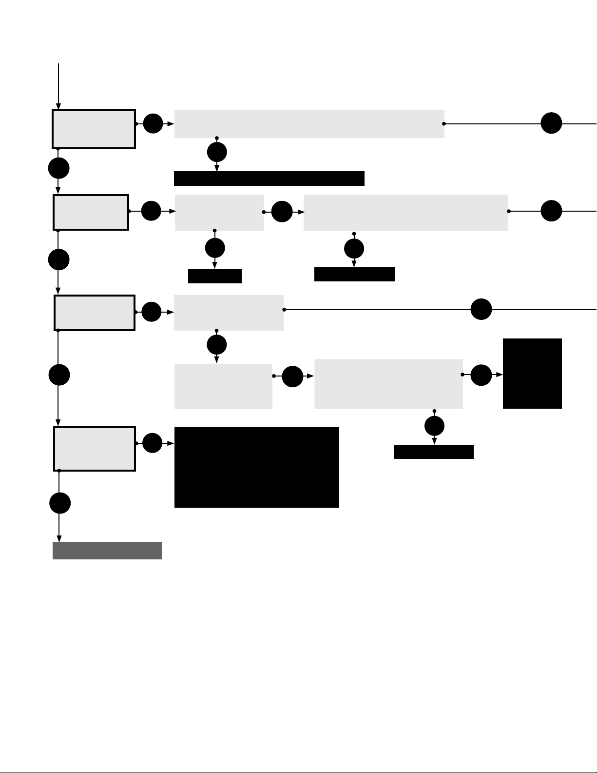
4.0 Troubleshooting Guide
Continued from page 14
DX2 Series
After ignitor is
warmed up, does
gas valve open?
Yes
Does the
burner ignite?
Yes
Does the burner
stay on?
Yes
No
No
No
Test for 120V at valve opening period (usually 30 to 45 seconds
after power to heater). Is there 120V to valve for 8 seconds?
No
Replace circuit board and/or wiring harness.
Is the gas supply
to the heater in
the ON position?
Yes
No
Turn on.
Does the burner stay on
for approx. 8 seconds
and then shut off?
Check to make sure gas pressure is within
minimum and maximum inputs, as indicated on
burner rating plate. Is gas pressure OK?
No
Correct problem.
No
Does the burner come
on and turn off
immediately (1 or 2
seconds)?
Yes
Check to make sure gas pressure
is within minimum and maximum
inputs, as indicated on the burner
rating plate. Is gas pressure OK?
Yes
Yes
Yes
Yes
Pressure
switch may
be faulty or
there is a
restriction in
the exhaust.
Does the heater
stay ON until a call
for heat ends?
Yes
Troubleshooting ends
No
The heater can shut down due to:
• Improper grounding.
• High winds.
• Taking combustion air from the attic.
• Dirty environment.
• Improperly positioned bafes.
• Fluctuating gas pressure.
No
Correct problem.
16
Page 17
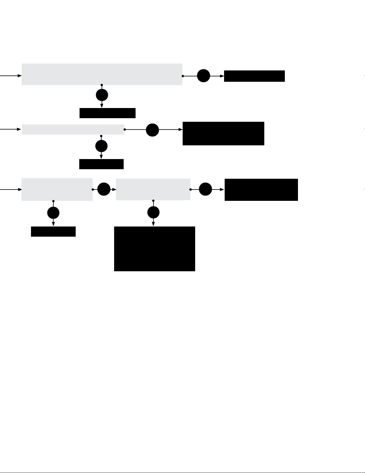
DX2 Series
Check to make sure gas pressure is within minimum and
maximum inputs, as indicated on burner rating plate.
Is gas pressure OK?
No
Correct problem.
Yes
4.0 Troubleshooting Guide
Replace gas valve.
Were the gas lines purged of air?
Purge gas line.
Is the heater properly
grounded? Is the heater’s
polarity correct?
No
Correct problem.
Yes
Conrm manifold pressure is
correct and/or gas orice is not
plugged and is the correct size.
No
With micrometer, check
Yes Yes
amperage at ame rod. Is it
greater than .7 microamps?
No
Sensing rod is faulty or ame
is weak. Check to make sure
heater is operating at proper
gas pressure as indicated on
burner rating plate and then, if
needed, replace sensing rod.
Check to make sure ame
sensor wire is OK. If so,
then replace circuit board.
17
Page 18
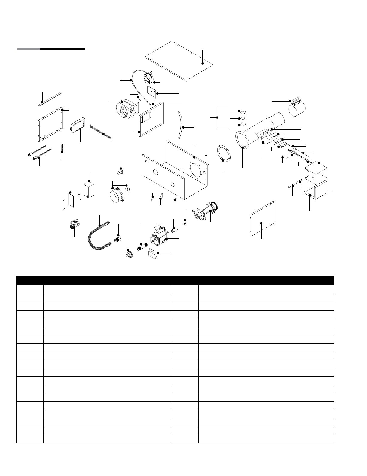
5.0 Parts • Heater Components and Parts List
DX2 Series
5.0 Parts
Figure 5.1 • Burner Assembly
Components
70
55A
302, 302A
351A
329
328
67
33B
352A
66
83
219
114
331
31B
84
301
76
212
13
NOPS
31B
207
97
13
204
223
TP-240, 241
208B
1
14
17
218
15
16
304, 804
5
200A or 201B
21B
217
380, 202
303
205
206
383A
50
214
10
321
221
222
222A
11
9
12
Chart 5.1 • Parts List
Part No. Description Part No. Description
TP-1 Control Box Cover TP-31B Control Box Mounting Bracket
TP-5 Flange Gasket TP-33B 1/2” Shut-Off Ball Valve / Inlet Tap
TP-9 Conduit Coupling TP-50 Glo-Bar™ Ignitor
TP-10 Conduit 4” x 1/2” TP-55A Fan Blower
TP-11 Glo-Bar™ Ignitor Box TP-65I 36” Interlocking Turbulator Bafe
TP-12 Glo-Bar™ Ignitor Box Cover TP-66 2” x 4” Outlet Box
TP-13 8 x 1/2” Self-Drilling Screw TP-67 2” x 4” Outlet Box Cover
TP-14 Sight Glass Gasket TP-70 Control Box Cover Gasket (per foot**)
TP-15 Sight Glass TP-76 Rubber Grommet
TP-16 Sight Glass Washer TP-82 Reector Center Support (RCS)
TP -17 Sight Glass Kit TP-83 24” Stainless Steel Flexible Gas Connector
TP-19 B 4” Wire Hanger with Tension Spring TP-84 1/2” Female / Male Flare Fitting
TP-20C 120” Aluminum Reector TP-97 1/4” x 1/4” Brass Int./Ext. Atmos. Barb Fitting
TP-20D 120” Stainless Steel Reector* TP-10 5 Aluminum Reector End Cap
TP-21B 4” Standard Tube Clamp TP-10 6 Reector End Cap Clips (8 pcs.)
TP-26A 10 ft. Coated-ALUM Combustion/Radiant Tube TP-113 Reector Tension Spring
TP-26B 10 ft. Coated-AL-TI Combustion Tube TP-114 Plastic Air Orice with Screen (consult factory)
TP-26D 10 ft. 304 Stainless Steel Radiant Tube* TP-200A Burner (Blue) - consult factory
TP-26E 10 ft. 409 Stainless Steel Combustion Tube* TP-201B Burner (Tan) - consult factory
*Stainless steel upgrades available. ** 6 feet total required to cover outer edges of the burner control box.
18
Page 19
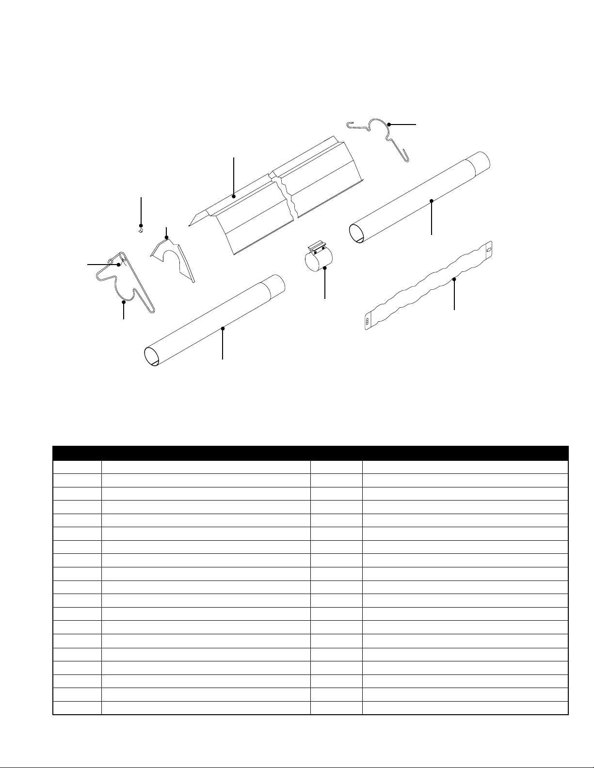
DX2 Series
Figure 5.2 • Tube & Reector Components
106
105
113
5.0 Parts • Heater Components and Parts List
82
20C, 20D
26A, 26D
21B, 220
65I
19B
26A, 26B, 26E
Part No. Description Part No. Description
TP-202 16” Burner Tube with Flange (ttings included) TP-301 Center Divider Panel
TP-204 Gas Orice (consult factory) TP-302 End Panel, Left
TP-205 Glo-Bar™ Holder TP-302A End Panel, Left with 24VAO Option.
TP-206 Glo-Bar™ Holder Spring Clip TP-303 End Panel, Right
TP-207 Pressure Switch Mounting Bracket TP-304 Burner Control Box Outer Shell w/ PC-36
TP-208B Gas Valve Mounting Bracket TP-321 Ignition Plate Gasket
TP-212 1/2” x 3” Pipe Nipple TP-328 120V Amber Operational Indicator Light
TP-214 Glo-Bar™ Wiring Harness TP-329 1/4” Neutral Terminal Block
TP -217 Pressure Switch Barb TP-331 Green Self Tap Ground Screw
TP-218 Differential Switch Vinyl Sensing Tube (exhaust) TP- 351A Potted Circuit Board
TP-219 Differential Vinyl Sensing Tube (burner) TP-352A Circuit Board Wiring Harness for TP-351A
TP-220 Stainless Steel Tube Clamp (175 & 200 MBH)* TP-380 16” Burner Tube with Flange (no ttings)
TP-221 Glo-Bar™ Holder Gasket TP-383A Glo-Bar™ Ignitor Plate
TP-222 Flame Rod TP-804 Burner Control Box Outer Shell
TP-222A Flame Rod Wire TP-NOPS Normally Open Pressure Switch; select below:
TP-223 Gas Manifold TP-264B Differential Pressure Switch, 65 to 100 MBH
TP-240 VR4205M-1324 Gas Valve Assembly - Nat. Gas TP-264E Differential Pressure Switch, 125 & 150 MBH
TP-2 41 VR4205M-1357 Gas Valve Assembly - LP Gas TP-264D Differential Pressure Switch, 175 MBH
TP-244 Plastic Gas Valve Vent TP-264F Differential Pressure Switch, 200 MBH
19
Page 20
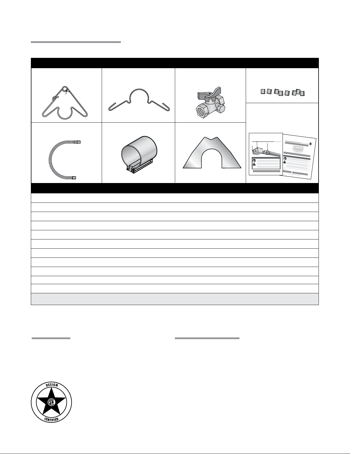
5.0 Parts • Kit Contents Check List
Kit Contents Check List
Chart 5.2 • Kit Contents for DX2 Series - Reference the length column for your model.
DX2 Series Kit Contents
DX2 Series
TP-19B 4” Hanger with
Reector Tension Spring
TP-83 24” Stainless Steel
Flexible Gas Connector
TP-82 4” Reector
Center Support (RCS)
TP-21B 4” Tube Clamp
TP-33B 1/2” Shut-Off Valve
(Ball Valve & Inlet Tap)
TP-105 Reector End Cap
TP-106 Reector
End Cap Clips
Tube Heater
General Manual and
DX2 Series Insert Manual
F/N: LIOGTa & LIODX2a
Tub e He a te r
General Manual
DX2 Series
Insert Manual
Part No. Description 20 Ft. 30 ft. 40 ft. 50 ft. 60 ft. 70 ft. 80 ft.
TP-19 B 4” Hanger w/ Tension Spring
TP-21B 4” Tube Clamp
TP-33B 1/2” Shut-Off Valve w/ Inlet Tap
TP-82 4” Reector Center Support
TP-83 24” S.S. Flexible Gas Connector
TP-10 5 Reector End Cap
TP-10 6 Reector End Cap Clips
LIOGTa General Tube Heater Manual
LIODX2a DX2 Series Insert Manual
Additional kit contents as supplied when heater is congured with Add- On Options (if applicable)
TP-25 1/4” Female Spade Terminal (24VAO)
3 4 5 6 7 8 9
2 3 4* 5* 6* 7* 8*
1 1 1 1 1 1 1
2 3 4 5 6 7 8
1 1 1 1
1 1 1
2 2 2 2 2 2 2
8 8 8 8 8 8 8
1 1 1 1 1 1 1
1 1 1 1 1 1 1
2 2 2 2 2 2 2
Filled By:
*NOTE: One 4” stainless steel tube clamp (P/N: TP-220) is provided for each 175,000 - 200,000 BTU model. Place
as shown on page 11.
Approvals
• CSA.
• Indoor approval.
• Outdoor approval with OD-Kit.
• Commercial approval.
Limited Warranty
• 1 year - Burner box components.
• 5 years - Combustion and radiant tubes.
• 10 years - Stainless steel burner.
• See page 36 of the General Tube Heater Manual
for terms and conditions.
© 2014 Detroit Radiant Products Co.
21400 Hoover Road • Warren, MI 48089
Phone: 586-756-0950 Fax: 586-756-2626
www.detroitradiant.com • [email protected]
Printed in U. S. A.
20
 Loading...