

Page 1
Detroit Radiant Products Company
!
FA Series Manual
Installation, Operation,
Maintenance and Parts
The FA Series heater is a gas-fired unit heater. This manual provides specific information related to the
FA Series models. All persons involved with the installation, operation and maintenance of the heater
system must read and understand the information in this manual.
Improper installation, adjustment, alteration, service or maintenance can cause
property damage, serious injury or death. Read and understand the installation,
operating and maintenance instruction thoroughly before installing or servicing this
equipment.
This heater must be installed and serviced by trained gas installation and service
personnel only. Failure to comply could result in personal injury, asphyxiation, death,
and fire or property damage.
Do not store or use gasoline or other flammable vapors and liquids in the vicinity of
this or any appliance.
Do not use this heater in indoor living or sleeping quarters! Installation of this unit in
a residential indoor living space may result in property damage, serious injury,
asphyxiation or death.
For Your Safety
If you smell gas:
• Open windows.
• Do not touch any electrical switch.
• Extinguish any open flame.
• Do not use any phone in your building.
WARNING
• Immediately call your gas supplier from a neighbor’s phone.
• Follow the gas supplier’s instructions.
• If you cannot reach your gas supplier, call the fire department.
INSTALLER: Present this manual to the end user.
Keep these instructions in a clean and dry place for future reference.
Model#: ___________________ Serial #: _________________________
(located on rating label)
LIOFA-Rev. 00413
Print: 1M-8/13_r1-5/14(CDS)
Page 2

Table of Contents
FA Series
Contents
1.0 Introduction . . . . . . . . . . . . . . . . . . . . . . . . . . . . . . . . . . . . . . . . . . . . . . . . . . . . . . . . . . . 3
Overview............................................................... 3
Heater Components . . . . . . . . . . . . . . . . . . . . . . . . . . . . . . . . . . . . . . . . . . . . . . . . . . . . . . 3
Initial Installation Considerations and Pre-Checks ............................... 4
Product Specifications . . . . . . . . . . . . . . . . . . . . . . . . . . . . . . . . . . . . . . . . . . . . . . . . . . . . 5
Safety Labels and Their Locations ........................................... 6
2.0 Safety . . . . . . . . . . . . . . . . . . . . . . . . . . . . . . . . . . . . . . . . . . . . . . . . . . . . . . . . . . . . . . 8
Warning Symbols . . . . . . . . . . . . . . . . . . . . . . . . . . . . . . . . . . . . . . . . . . . . . . . . . . . . . . . . 8
Applications . . . . . . . . . . . . . . . . . . . . . . . . . . . . . . . . . . . . . . . . . . . . . . . . . . . . . . . . . . . . 8
Standards, Certifications and Government Regulations........................... 9
Clearance to Combustibles ................................................ 11
3.0 Inst allation . . . . . . . . . . . . . . . . . . . . . . . . . . . . . . . . . . . . . . . . . . . . . . . . . . . . . . . . . . . . 12
Recommended Mounting Heights ........................................... 13
Gas Supply Installation Instructions . . . . . . . . . . . . . . . . . . . . . . . . . . . . . . . . . . . . . . . . . . 14
Leak Testing . . . . . . . . . . . . . . . . . . . . . . . . . . . . . . . . . . . . . . . . . . . . . . . . . . . . . . . . . . . . 17
Electrical Requirements and Wiring Diagrams .................................. 18
Internal Wiring Diagrams . . . . . . . . . . . . . . . . . . . . . . . . . . . . . . . . . . . . . . . . . . . . . . . . . . 18
Field Wiring Supply Voltage . . . . . . . . . . . . . . . . . . . . . . . . . . . . . . . . . . . . . . . . . . . . . . . . 19
Thermostat Connection ................................................... 21
Thermostat Location...................................................... 22
Venting . . . . . . . . . . . . . . . . . . . . . . . . . . . . . . . . . . . . . . . . . . . . . . . . . . . . . . . . . . . . . . . . 23
Replacing Existing Equipment . . . . . . . . . . . . . . . . . . . . . . . . . . . . . . . . . . . . . . . . . . . . . . 23
General Venting Requirements.............................................. 24
Vertical Venting (Category I)................................................ 26
Horizontal Venting (Category III)............................................. 27
Common Venting (Category I) . . . . . . . . . . . . . . . . . . . . . . . . . . . . . . . . . . . . . . . . . . . . . . 29
Concentric Venting ....................................................... 30
Combustion Air Requirements . . . . . . . . . . . . . . . . . . . . . . . . . . . . . . . . . . . . . . . . . . . . . . 30
Separated Combustion Systems . . . . . . . . . . . . . . . . . . . . . . . . . . . . . . . . . . . . . . . . . . . . 31
Room Air Combustion Systems . . . . . . . . . . . . . . . . . . . . . . . . . . . . . . . . . . . . . . . . . . . . . 33
Unit Start-Up (Commissioning) .............................................. 34
Pre-Start Up Checks...................................................... 34
Verify Proper Inlet Pressure . . . . . . . . . . . . . . . . . . . . . . . . . . . . . . . . . . . . . . . . . . . . . . . . 35
Verify Manifold Pressure................................................... 36
Prior to leaving the Job Site . . . . . . . . . . . . . . . . . . . . . . . . . . . . . . . . . . . . . . . . . . . . . . . . 37
High Altitude Operation.................................................... 38
4.0 Operation..............................................................40
Sequence of Operation.................................................... 40
Shutdown Procedures..................................................... 41
Troubleshooting Guide . . . . . . . . . . . . . . . . . . . . . . . . . . . . . . . . . . . . . . . . . . . . . . . . . . . . 42
5.0 Maintenance . . . . . . . . . . . . . . . . . . . . . . . . . . . . . . . . . . . . . . . . . . . . . . . . . . . . . . . . . . . 46
Heater Assembly Components and Parts List . . . . . . . . . . . . . . . . . . . . . . . . . . . . . . . . . . 48
Maintenance Log . . . . . . . . . . . . . . . . . . . . . . . . . . . . . . . . . . . . . . . . . . . . . . . . . . . . . . . . 54
Limited Warranty Terms and Conditions . . . . . . . . . . . . . . . . . . . . . . . . . . . . . . . . . . . . . . 55
Kit Contents . . . . . . . . . . . . . . . . . . . . . . . . . . . . . . . . . . . . . . . . . . . . . . . . . . . . . . . . . . . . 56
2
Page 3
FA Series
1.0 Introduction • Overview • Heater Components
1.0 Introduction
Overview
The intent of this manual is to provide information regarding safety, design guidelines, installation,
operation and maintenance of the FA Series gas-fired unit heater. You must read and understand the
instructions and all safety warnings before installing the gas-fired unit heater. This manual is property of
the owner, and must stay with the owner or unit after installation is complete.
Heater Components
Prior to installation, verify that the heater’s gas type and voltage (as listed on the rating plate) match
that of your application. Also verify that you have received the entire heater contents included with your
unit. Refer to page 56 for a list of the kit contents for your heater. Materials not included with the unit
(e.g. screws, vent material, threaded rod, etc.) are the responsibility of the installer. Notify your product
representative or the factory of any discrepancy of missing items prior to installing the unit.
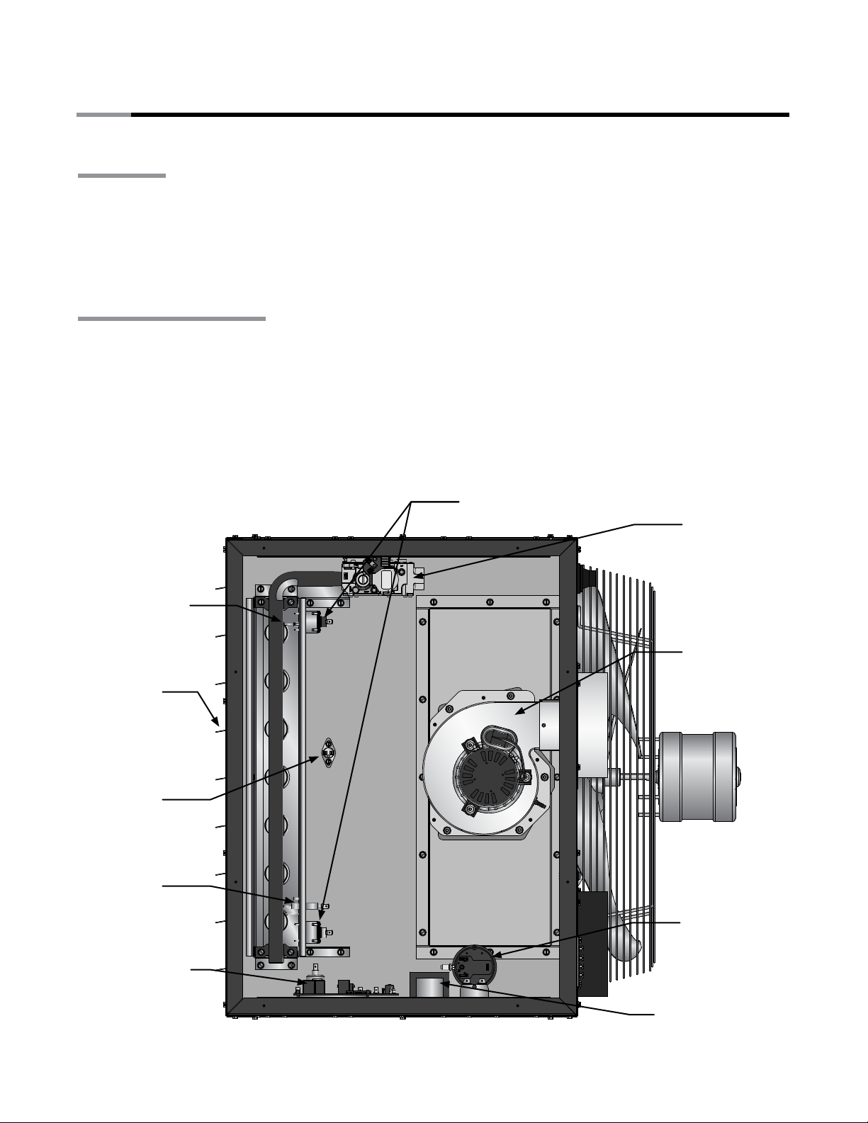
Figure 1.1 • Heater Subcomponents
Flame Sensor
Louvers
High Limit
Switch
Flame Rollout
Switches
Gas Valve
Draft Inducer
Spark
Igniter
Direct Spark
Igniter Board
Pressure
Switch
Control
Transformer
3
Page 4

!
!
1.0 Introduction • Initial Installation Considerations and Pre-Checks
FA Series
Initial Installation Considerations and Pre-Checks
WARNING
Improper installation, adjustment, alteration, service or maintenance can cause
property damage, serious injury or death. Read and understand the installation,
operating, and maintenance instructions thoroughly before installing or servicing this
equipment. Only a trained, qualified installation or service personnel may install or
service this equipment.
Placement of the heater is influenced by many factors. Aside from safety factors, considerations for
the general space and heating requirements, availability of gas and electrical supply, and proximity of
possible vent locations are a few examples of factors that should all be considered.
Inspect and evaluate the location of the heater to ensure that the structural support is adequate to
support the unit’s weight. The unit must be installed in a horizontally level position to ensure proper
operation. To reduce noise attenuation along the structure caused by vibration of the unit, the heater
should be installed within 15 feet of a primary building support. In the cases where this installation is
not practical or feasible, the use of spring vibration isolators may be used, so long as they are rated for
use of the unit’s weight (see Chart 1.1).
Adequate space around the heater must also be considered in order to maintain the published
minimum clearance to combustibles and recommended service clearances.
When designing a unit heater system, consider the following:
• Has the building’s heat loss been evaluated?
• Does the design meet the needs of the space?
• Have the recommended mounting heights been observed?
WARNING
Do not locate any gas-fired units in area where chlorinated, halogenated, or acid vapors are
present in the atmosphere. These substances can cause premature heat exchanger failure due
to corrosion, which can cause property damage, serious injury or death.
4
Page 5
FA Series
1.0 Introduction • Product Specifications
Product Specifications
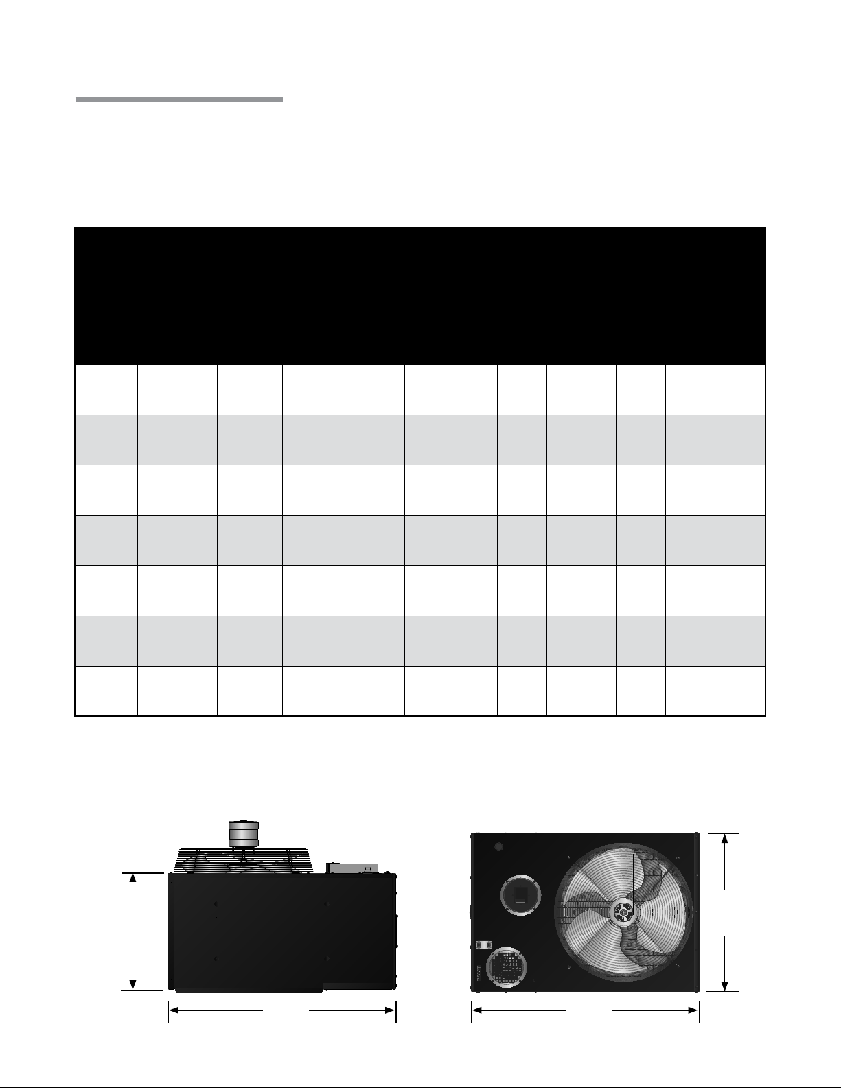
The FA Series unit heater is a single input warm air heater with an average thermal efficiency of 80%,
unless otherwise indicated on the rating label. All units are to be supplied with single-phase 60 Hz
120VAC power. The exterior of all models are finished with industrial-grade colored enamel. For specific
information on each model, see Chart 1.1, below.
Chart 1.1 • Specifications
Model Number
FA-10 0
FA-125
FA-15 0
FA-175
FA-20 0
FA-225
FA-250
Cabinet Number
Gas Type
Nat or
3
LP
Nat or
3
LP
Nat or
4
LP
Nat or
4
LP
Nat or
4
LP
Nat or
5
LP
Nat or
5
LP
BTU/h Input
100,000 80,000
125,000 100,000
150,000 120,000
175,000 140,000
200,000 160,000
225,000 180,000
250,000 200,000
BTU/h Output
Physical
40” W
20” D
21” H
40” W
20” D
21” H
40” W
20” D
27” H
40” W
20” D
27” H
40” W
20” D
27” H
40” W
20” D
30” H
40” W
20” D
30” H
Dimensions
118
Lbs.
118
Lbs.
159
Lbs.
159
Lbs.
159
Lbs.
176
Lbs.
176
Lbs.
Standard Weight
Recommended
Mounting Height*
12'-14'
14'-16 '
14'-16 '
15' -17 '
15' -17 '
16'-18'
16'-18'
Gas Connection
1/2"
NPT
1/2"
NPT
1/2"
NPT
1/2"
NPT
1/2"
NPT
3/4"
NPT
3/4"
NPT
Vent Connection
Inlet Connection
Axial Fan
4” 4” CCW
4” 4” CCW
6” 6” CCW
6” 6” CCW
6” 6” CCW
6” 6” CCW
6” 6” CCW
Rotation
Primary Voltage
Thermostat
Voltage
120
VAC
120
VAC
120
VAC
120
VAC
120
VAC
120
VAC
120
VAC
24
VAC
24
VAC
24
VAC
24
VAC
24
VAC
24
VAC
24
VAC
* Recommended mounting heights are provided as a guideline. Actual conditions may dictate variations
from the above data. Clearance to combustibles must always be maintained.
Figure 1.2 • Dimensional Data (see Chart 1.1 for Physical Dimensions)
Top View
D
w
5
ReaR View
H
w
Page 6
1.0 Introduction • Safety Labels and Their Locations
(586) 756-0950 - www.drp-co.com
FA Series
Safety Labels and Their Locations
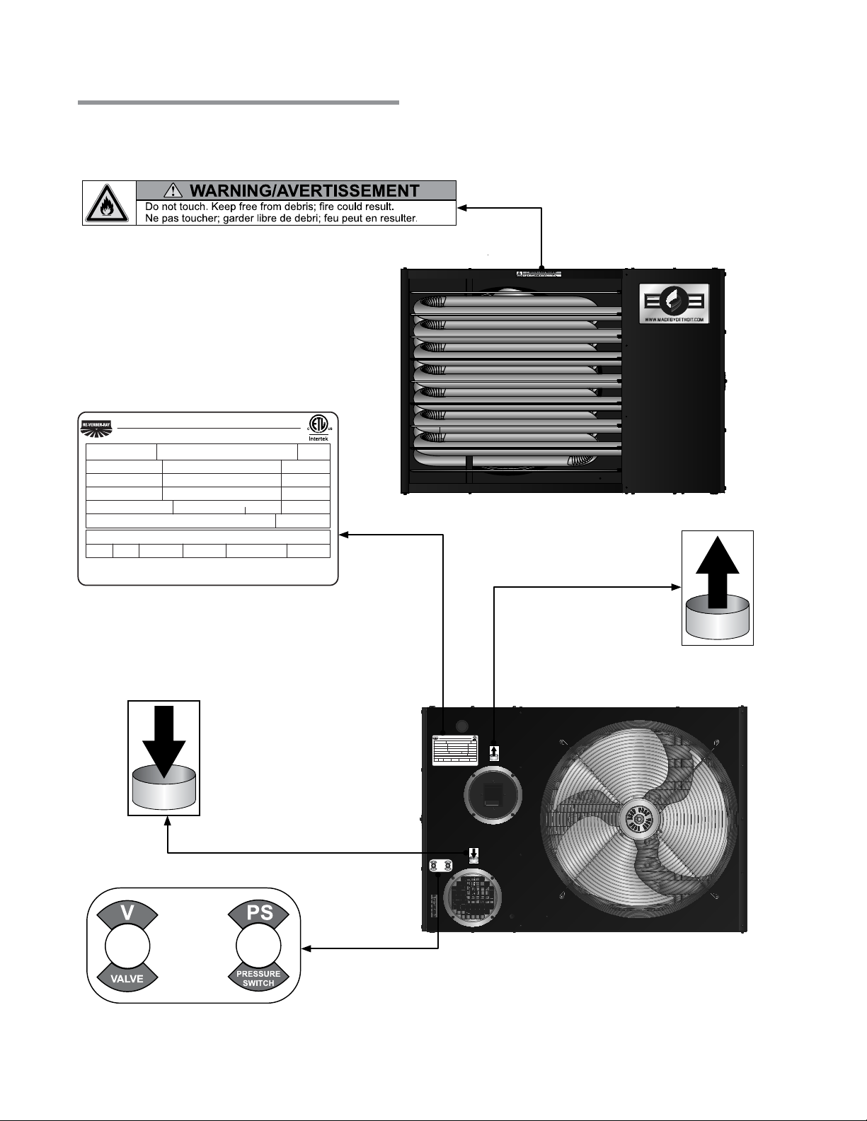
Product safety signs or labels should be replaced by the product user when they are no longer legible.
Contact either your local distributor or product manufacturer for obtaining replacement signs or labels.
F/N: LLUH002 - Do Not Touch
SEPARATED COMBUSTION SYSTEM UNIT HEATER
MODEL NUMBER
NUMÉRO DE MODÈLE
TYPE OF GAS
TYPE DE GAZ
HEAT INPUT
DEBIT CALORIFIQUE
HEAT OUTPUT
REDENMENT
VENT CATAGORY
ÉVENT CATÉGORIE
THIS DESIGN COMPLIES WITH UNIT HEATER STANDARD:
ANSI Z83.8b-2006 • CSA2.6B-2006 UNIT HEATER
TOP
HAUT
DETROIT RADIANT PRODUCTS COMPANY
21400 HOOVER ROAD - WARREN, MI 48089
(586) 756-0950 - www.drp-co.com
AÉROTHERME À SYSTÈME DE COMBUSTION ISOLÉ
SERIAL NUMBER
NUMÉRO DE SÉRIE
FA-200N
NATURAL
200,000
160,000
CATAGORY III
DÉGAGEMENT MINIMUM POUR MATIÉRES COMBUSIBLES
RIGHT SIDE
BOTTOM
BAS
COTÉ DROIT
INCH
INCH
1 1 1 6
1
YYMMREPCSHIPPE#### 09/12
MANIFOLD PRESSURE
PRESSION A LA TUBULURE D'ALIMENTATION
MAXIMUM INLET PRESSURE
PRESSION D'ALIMENTATION MAXIMALE
BTU/h
MINIMUM INLET PRESSURE FOR PURPOSE OF ADJ.
PRESSION D'ALIMENTATION EN GAS MIN. ADMISE
BTU/h
ORIFICE SIZE
DIM DE L'INJECTEUR
SAMPLE
MINIMUM CLEARANCE TO COMBUSTIBLE MATERIAL
LEFT SIDE
COTÉ GOUCHE
INCH INCH INCH INCH
INCHES W.C.
14.0
INCHES W.C.
INCHES W.C.
5.0
NATURAL GAS PROPANE GAS
D.M.S. D.M.S.
57
49
VENT CONNECTOR
CONNECTEUR D'AERATION
FOR COMMERCIAL / INDUSTRIAL USE.
FOR INDOOR USE ONLY.
Rating Label (Inside of Panel)
VOLTAGE
AMPS
PHASE
FREQUENCY
LABEL REVISION
MADE IN U.S.A.
VERSION
1203.5
SINGLE
SERVICE ACCESS
COTÉ ACCÉDEZ
VAC
2.4
Hz
60
Front View
A
18
F/N: LLUH004 - Air In
F/N: LLV3EP6 - Gas Valve and
Pressure Switch Operation
SEPARATED COMBUSTION SYSTEM UNIT HEATER
AÉROTHERME À SYSTÈME DE COMBUSTION ISOLÉ
MODEL NUMBER
SERIAL NUMBER
NUMÉRO DE MODÈLE
NUMÉRO DE SÉRIE
FA-200N
YYMMREPCSHIPPE#### 09/12
MANIFOLD PRESSURE
TYPE OF GAS
TYPE DE GAZ
PRESSION A LA TUBULURE D'ALIMENTATION
NATURAL
HEAT INPUT
MAXIMUM INLET PRESSURE
DEBIT CALORIFIQUE
PRESSION D'ALIMENTATION MAXIMALE
200,000
BTU/h
HEAT OUTPUT
MINIMUM INLET PRESSURE FOR PURPOSE OF ADJ.
REDENMENT
PRESSION D'ALIMENTATION EN GAS MIN. ADMISE
160,000
BTU/h
ORIFICE SIZE
VENT CATAGORY
DIM DE L'INJECTEUR
ÉVENT CATÉGORIE
CATAGORY III
THIS DESIGN COMPLIES WITH UNIT HEATER STANDARD:
ANSI Z83.8b-2006 • CSA2.6B-2006 UNIT HEATER
MINIMUM CLEARANCE TO COMBUSTIBLE MATERIAL
DÉGAGEMENT MINIMUM POUR MATIÉRES COMBUSIBLES
TOP
LEFT SIDE
RIGHT SIDE
BOTTOM
HAUT
BAS
COTÉ DROIT
COTÉ GOUCHE
INCH
INCH INCH INCH INCH
INCH
1 1 1 6
1
DETROIT RADIANT PRODUCTS COMPANY
21400 HOOVER ROAD - WARREN, MI 48089
F/N: LLUH005
Vent Out
VERSION
VOLTAGE
VAC
INCHES W.C.
1203.5
AMPS
2.4
14.0
INCHES W.C.
PHASE
SINGLE
INCHES W.C.
5.0
NATURAL GAS PROPANE GAS
FREQUENCY
D.M.S. D.M.S.
Hz
57
49
60
LABEL REVISION
A
VENT CONNECTOR
SERVICE ACCESS
CONNECTEUR D'AERATION
COTÉ ACCÉDEZ
18
FOR COMMERCIAL / INDUSTRIAL USE.
FOR INDOOR USE ONLY.
MADE IN U.S.A.
Rear View
6
Page 7
FA Series
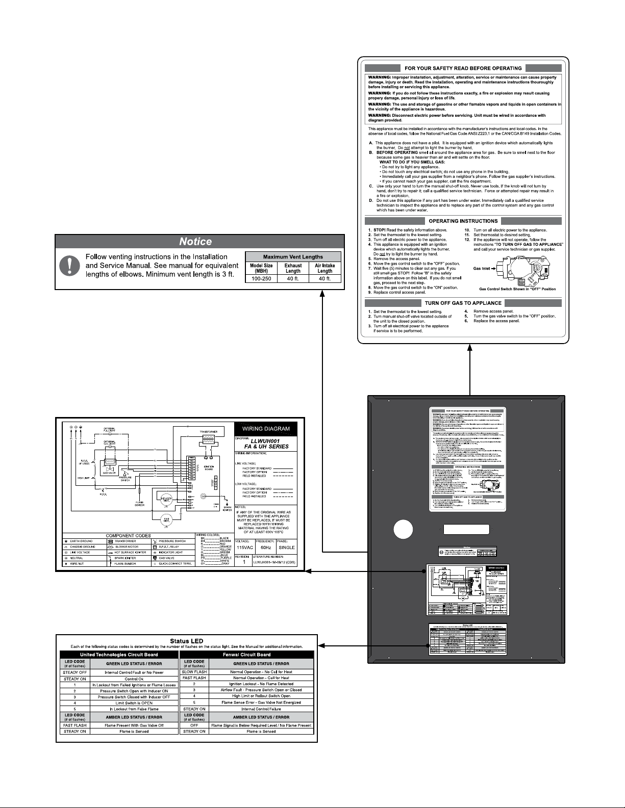
F/N: LLUH007
FA Vent Length Notice
1.0 Introduction • Safety Labels and Their Locations
F/N: LLWUH001 - Wiring Diagram
F/N: LLUHCL001
For Your Safety
F/N: LLUH001 - LED Status
Service Access Door View
(Inside View)
7
Page 8
2.0 Safety • Warning Symbols • Applications
!
!
!
!
FA Series
2.0 Safety
Read and understand all safety information and warnings in this manual prior to installation, operation,
and maintenance of this unit heater. Warnings indicate a potentially hazardous situation which, if not
avoided, could result in death or injury.
WARNING
Improper installation, adjustment, alteration, service or maintenance can cause property
damage, serious injury or death. Read and understand the installation, operating and
maintenance instructions thoroughly before installing or servicing this equipment. Only
trained qualified gas installation and service personnel may install or service this
equipment.
Warning Symbols
Safety is the most important consideration during installation, operation and maintenance of the unit
heater. You will see the following symbols and signal words when there is a hazard related to safety or
property damage.
Warning indicates a potentially hazardous
WARNING
CAUTION
NOTICE
situation which, if not avoided, could result in
death or injury.
Caution indicates a potentially hazardous
situation which, if not avoided, could result in
minor or moderate injury.
Notice indicates a potentially hazardous
situation which, if not avoided, could result in
property damage.
Applications
This is not an explosion proof heater. This heater may not be used in a Class 1 or Class 2 Explosive
Environment. Consult your local Fire Marshall, insurance carrier and other authorities for approval if the
proposed installation is in question.
Commercial / Industrial
The FA Series unit heater is designed and certified for use in industrial and commercial buildings, such
as warehouses, manufacturing plants, aircraft hangars, and vehicle maintenance shops. For maximum
safety, the building must be evaluated for potential problems before installing the heater system. This
unit is certified for use as furnished by the manufacturer. Do not alter the fan or operate motors at a
reduced speed.
CAUTION
Installation of restrictive devices to the inlet or outlet of the fan motor may result in premature
failure of the exchanger pipe, overheating of the appliance, or damage to the components. Do
not attach ductwork, air filters, or poly-tubes to any FA Series unit heater.
8
Page 9
FA Series
2.0 Safety • Standards, Certifications and Government Regulations
Standards, Certifications and Government Regulations
Installation of this gas-fired heater must conform with all applicable local, state and national
specifications, regulations and building codes. Contact the local building inspector and/or Fire Marshall
for guidance.
In the absence of local codes, the installation must conform to the latest edition of:
United States: National Fuel Gas Code, ANSI Z223.1 (NFPA 54).
Canada: CAN/CGA B149.1 and .2, Canadian Electrical Code C22.1
Copies of these Standards can be viewed or purchased at www.nfpa.org or www.scc.ca.
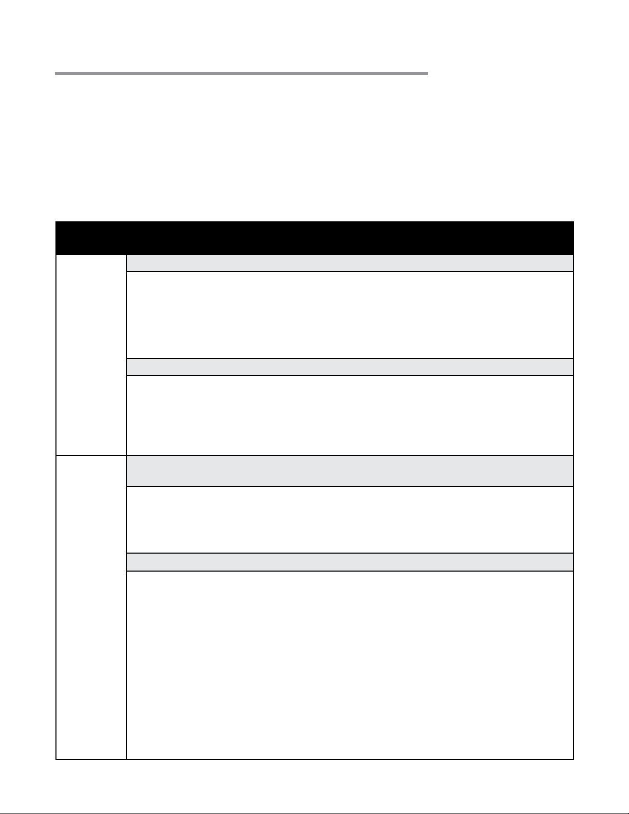
Chart 2.1 • Standard and Code Installation Guidelines • Building Type
Building
Type
Public
Garages
Aircraft
Hangars
Codes and Guidelines
Installation of this heater in public garages must conform to the following codes:
United States: Standard for Parking Structures NFPA 88A (latest edition) or the
Code for Motor Fuel Dispensing Facilities and Repair Garages
NFPA 30A (latest edition).
Canada: Refer to CAN/CGA B149.1: Installation Codes for Gas Burning Appliances
and applicable Standards for Public Garages.
Guidelines:
• Heaters must not be installed less than 8 ft. (2.4 m) above the floor. Minimum
clearances to combustibles must be maintained from vehicles parked below the
heater.
• When installed over hoists, minimum clearances to combustibles must be
maintained from the upper most point of objects on the hoist.
Installation of this heater in aircraft hangars must be in accordance with the following
codes:
United States: Refer to Standard for Aircraft Hangars, ANSI/NFPA 409
(latest edition).
In Canada: Refer to Standard CAN/CGA B149.1 and applicable Standards for
Aircraft Hangars.
Guidelines:
• In aircraft storage and servicing areas, heaters shall be installed at least 10 ft. (3 m)
from above the upper surface of wings or of the engine enclosures of the highest
aircraft that may be housed in the hangar. The measurement shall be made from
the wing or engine enclosure, whichever is higher from the floor, to the bottom of
the heater.
• In areas adjoining the aircraft storage area (e.g., shops, offices) the bottom of
heaters shall be installed no less than 8 ft. (2.4 m) above the floor.
• Suspended or elevated heaters shall be located in spaces where they shall not be
subject to damage by aircraft, cranes, movable scaffolding or other objects.
Provisions shall be made to assure accessibility to suspended heaters for recurrent
maintenance purposes.
9
Page 10
2.0 Safety • Standards, Certifications and Government Regulations
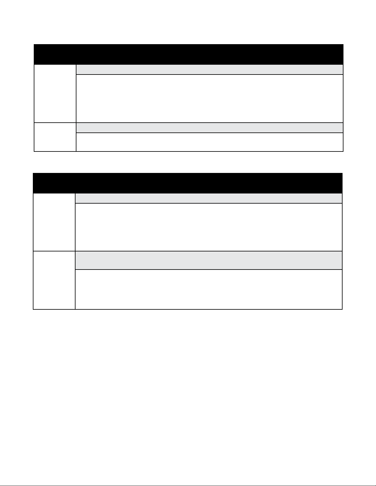
Chart 2.2 • Standard and Code Installation Guidelines • Building Location
FA Series
Building
Location
High
Altitude
NonStandard
BTU Gas
Chart 2.3 • Standard and Code Installation Guidelines • Building Aspect
Building
Aspect
Electrical
Guidelines
Installation of this heater is approved, without modifications, for elevations up to 2,000
feet (610 m) above MSL (sea level) in the United States. For elevations above 2,000
feet, the heater input must be derated. See page 38 for details on how to derate.
The type of gas appearing on the nameplate must be the type of gas used. Installation
must comply with national and local codes and requirements of the local gas company.
Guidelines:
Unless otherwise noted on the rating plate, this heater is designed and orificed to
operate on standard BTU gas. Contact the factory if utilizing non-standard BTU gas.
Codes and Guidelines
The heater must be electrically grounded in accordance with the following codes:
United States: Refer to National Electrical Code
Wiring must conform to the latest edition of National Electrical
Code®, local ordinances, and any special diagrams furnished.
Guidelines
®
, ANSI/NFPA 70 (latest edition).
Canada: Refer to Canadian Electrical Code CSA C22.1 Part 1 (latest
edition).
Venting
Applicable authorities governing the manufacturing or installation of this unit here include (but are not
limited to) the following organizations:
In the United States:
• NFPA 54 / ANSI Z223.1 – National Fuel Gas Code.
• ANSI Z83.8 / CSA 2.6 – Gas Unit Heater Construction Standard.
• ANSI/NFPA 70 - National Electric Code.
In the Canada:
• CAN/CGA B149.1-10 – Natural Gas and Propane Installation Code.
Venting must be installed in accordance with the requirements within this manual and
the following codes:
United States: Refer to NFPA 54/ANSI Z223.1 (latest edition), National Fuel
Gas Code.
Canada: Refer to CAN/CGA B149.1 Installation Codes for Gas Burning
Appliances.
• ANSI Z83.8 / CSA 2.6 – Gas Unit Heater Construction Standard.
• C22.1 Part 1 – Canadian Electrical Code.
10
Page 11
FA Series
!
2.0 Safety • Clearance to Combustibles
Clearance to Combustibles
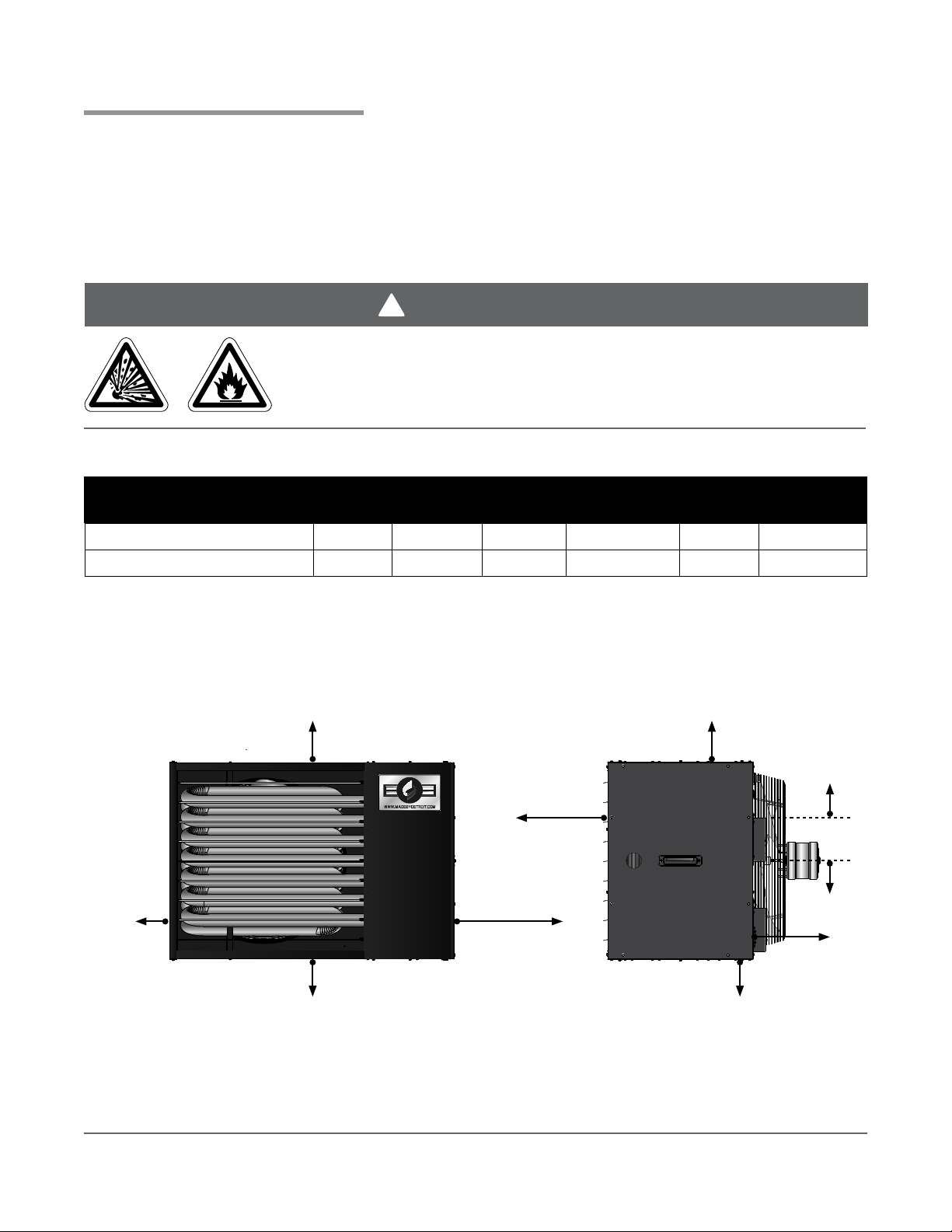
Clearance to combustibles is defined as the minimum distance that must exist between the specified
feature of the heater, and any combustible items. It also pertains to the distance that must be
maintained from moving objects around the unit heater. A recommended service clearance is defined
as the minimum distance that is needed to properly service the heater. When installing the unit heater,
clearances to combustible for the model heater must be maintained. Refer to Chart 2.4 to determine the
required distances for your model.
WARNING
Placement of explosive objects, flammable objects, liquids and vapors
close to the heater may result in explosion, fire, property damage,
serious injury or death. Do not store or use explosive objects, liquids or
vapor in the vicinity the heater.
Chart 2.4 • Clearances to Combustible Materials (in Inches) Commercial Models
Top and
Unit Side Front
Clearance to Combustibles
Clearance to Allow Service
60 1 18 1 1 6
60 1 18 1 18 6
Bottom
Figure 2.1 • Clearance to Combustibles Diagram
FRONT VIEW SIDE VIEW
Top
Non-Access
Side
Access
Side
Front
Access
Side
Non-Access
Side Rear
Vent
Connection
Top
Vent
Connection
Rear
Bottom
Bottom
11
Page 12
3.0 Installation
!
FA Series
3.0 Installation
NOTICE
High humidity or saltwater atmospheres will accelerate heater corrosion and reduce useful life. Do not
install the heater in locations where water (in the form of rain, drips, or spray) could fall onto the gas
ignition components.
WARNING
Improper suspension of the unit heater may result in collapse and being crushed.
Always suspend from a permanent part of the building structure that can evenly
support the total force and weight of the heater.
Failure to maintain minimum clearance to combustibles may result in fire and/ or
explosion, property damage, serious injury or death. Always maintain minimum
clearances.
The suspension of the heater must conform to all applicable codes referenced in the safety section and
these instructions.
To ensure proper operation, the heater must be installed in a level horizontal position. The units are
designed to be hung with threaded rod via the four (4) threaded inserts on the top panel of the heater.
Determine desired mounting points, and mark the locations for the hanging points.
1
Prepare the mounting surface. If necessary, weld blocks, drill holes, or install additional bracketing
2
or steel channel.
Fasten beam clamp, screw hook, turnbuckle, steel channel, or other anchoring device to the
3
suspension points.
Determine the desired mounting height. Cut four pieces of 3/8”-16 threaded rod of equal length in
4
which the heater will be hung from. Ensure that the threads are not damaged during the cutting
process.
Using 3/8”-16 threaded rod, thread a nut up one end at a distance of approximately 1 inch. This is
5
the end that will be screwed into the heater.
Next, place a lock washer on top of the nut and thread the rod assembly into the unit heater’s
6
threaded inserts. A minimum of 2-3 complete threads must be exposed on the reverse side of the
threaded insert (approx. 9-10 turns), but no more than 20 turns, as this may cause the threaded rod
to collide with or damage the heat exchanger.
Tighten down the previously installed jam nuts to prevent the threaded rod from turning.
7
Attach threaded rod to prepared anchoring device. Adjust the threaded rod until the unit is level and
8
equal weight distribution is achieved. Threaded rod must be perpendicular with the unit. Do not
install threaded rods at an angle, as this can result in weakened structural integrity or undue noise.
12
Page 13
FA Series
Recommended Mounting Heights
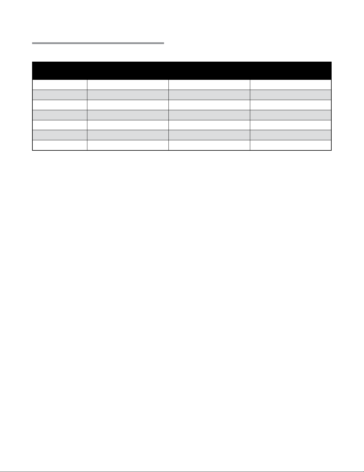
Chart 3.1 • Recommended Mounting Heights*
3.0 Installation • Recommended Mounting Heights
Model
FA-100
FA-12 5
FA-15 0
FA-175
FA-200
FA-225
FA-250
Typical
Mounting Height
12 to 14 ft. 43 ft. 50°F
14 to 16 ft. 57 ft. 50°F
14 to 16 ft. 52 ft. 50°F
15 to 17 ft. 51 ft. 50°F
15 to 17 ft. 55 ft. 50°F
16 to 18 ft. 59 ft. 50°F
16 to 18 ft. 63 ft. 50°F
Approximate
Heat Throw
Average Air
Temperature Rise
* Recommended mounting heights are provided as a guideline. Actual conditions may dictate
variations from the above data. Clearance to combustibles must always be maintained.
The recommended mounting heights of the units are critical to its performance. Refer to the Chart 3.1
for specific recommended mounting heights. The mounting height is measured from the finished floor to
the bottom of the unit. Units that are mounted higher than the recommended mounting heights may not
directly deliver heated air to the floor level.
13
Page 14
3.0 Installation • Gas Supply Installation Instructions
!
!
WARNING
Improperly connected gas lines may result in serious injury and death,
explosion, poisonous fumes, toxic gases or asphyxiation. Connect gas lines
in accordance to national, state, provincial and local codes.
Gas pressure to the appliance controls must never exceed ½” PSI (14” W.C.). Damage to the
controls may result.
CAUTION
Gas lines should be purged of air as described in ANSI Z223.1 (NFPA 54) or CSA-B149.1– latest
version. Installation of the piping must also conform with the local building codes, or in the
absence of local codes, with the latest edition of the National Fuel Gas Code (NFPA 54). In
Canada, installation must be in accordance with CSA-B149.1
FA Series
NOTICE
The total input to the appliance must fall within +/- 5% of the rated input as indicated on the
rating plate. Otherwise the heat exchanger may prematurely fail.
Gas Supply Installation Instructions
The gas supply to the unit heater must be connected and tested in accordance with national, state,
provincial, and local codes along with guidelines in this manual. In the United States refer to the latest
edition of the ANSI Z223.1 (NFPA54) Standard and in Canada refer to the latest edition of the CAN/GCA
B149.1 Standard.
Supply gas piping to the unit should conform with the local and national requirements for type and
volume of gas handled, and pressure drop allowed in the line. Avoid pipe sizes smaller than 1/2”.
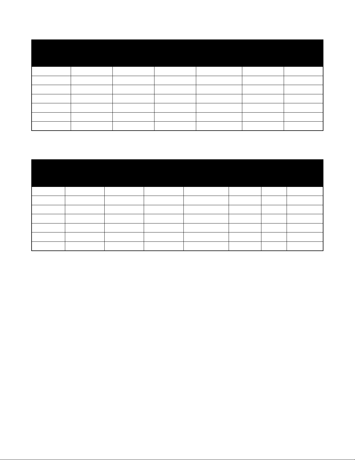
Refer to Chart 3.2 for natural gas and Chart 3.3 for propane to determine the cubic feet per hour (CFH)
required for the type of gas and size of unit to be installed. To determine the proper pipe diameter, use
the CFH value and the length of pipe necessary from Chart 3.4. In the case where several units are
serviced by the same main gas line, the total capacity (CFH) and length of main must be adequate to
service all appliances downstream of this main.
14
Page 15
FA Series
Chart 3.2 • Natural Gas Consumption
3.0 Installation • Gas Supply Installation Instructions
Model
FA-100 N
FA-12 5N
FA-15 0N
FA-175N
FA-200 N
FA-225N
FA-250N
Manifold
Pressure
(Inches W.C.)
3.5 5.0 14.0 95.2 42 DMS 4
3.5 5.0 14.0 119 . 0 42 DMS 5
3.5 5.0 14.0 142. 9 42 DMS 6
3.5 5.0 14.0 166.7 42 DMS 7
3.5 5.0 14.0 190.5 39 DMS 7
3.5 5.0 14.0 214.3 42 DMS 9
3.5 5.0 14.0 23 8 .1 40 DMS 9
Min. Inlet
Pressure
(Inches W.C.)
Max. Inlet
Pressure
(Inches W.C.)
Gas
Consumption
(CFH)*
Orifice
Size
*Assumes an average heating value of 1050 BTU/SCF and a Specific Gravity of 0.60.
Chart 3.3 • Propane Gas Consumption
Model
FA-100 P
FA-12 5P
FA-15 0P
FA-175P
FA-200 P
FA-225P
FA-250P
Manifold
Pressure
(Inches W.C.)
10.0 11. 0 14.0 40.0 1.10 54 DMS 4
10.0 11. 0 14.0 50.0 1.37 54 DMS 5
10.0 11. 0 14.0 60.0 1.6 5 54 DMS 6
10.0 11. 0 14.0 70.0 1.92 54 DMS 7
10.0 11. 0 14.0 80.0 2.20 1.45 mm 7
10.0 11. 0 14.0 90.0 2.47 54 DMS 9
10.0 11. 0 14.0 100.0 2.75 1.45mm 9
Min. Inlet
Pressure
(Inches W.C.)
Max. Inlet
Pressure
(Inches W.C.)
Gas
Consumption
(CFH)*
Gallons
per hour
Orifice
*
Size
Number
of Orifices
Number of
Orifices
*Assumes an average heating value of 2500 BTU/SCF and a Specific Gravity of 1.53.
Chart 3.4 allows for a 0.3 inch W.C. pressure drop in the supply pressure from the building main to the
inlet of the unit. Refer to the chart for the appropriate range of inlet pressures for each gas type. When
sizing the inlet gas pipe diameter, make sure that the unit supply pressure can be met after the 0.3 inch
W.C. pressure drop has been subtracted from the main pressure. If the 0.3 inch W.C. pressure drop is
too high, refer to NFPA 54 or the Gas Engineer’s Handbook for other gas pipe capacities.
15
Page 16

!
3.0 Installation • Gas Supply Installation Instructions
Chart 3.4 • Maximum capacity for Schedule 40 Metallic pipe, in CFH
FA Series
Pipe
Length
(feet)
10’
20’
30’
40’
50’
60’
70’
80’
90’
100’
125’
150’
175’
200’
The FA Series heater is equipped to receive a gas supply line nipple of either ½”NPT or ¾”NPT
Schedule 40 metallic pipe. All piping must be installed in accordance with the requirements outlined in
the National Fuel Gas Code ANSI/Z223.1 (latest edition) or CSA-B149.1 and B149.2. Support all gas
supply piping with pipe hangers, metal strapping, or other suitable material. Do not rely on the heater to
support the gas pipe.
1/2” 3/4” 1” 1-1/4” 1-1/2” 2”
Nat L . P. Nat L .P. Nat L .P. Nat L .P. Nat L .P. Nat L .P.
132 86 278 182 520 340 1050 686 1600 1046 3050 1993
92 60 190 124 350 229 730 477 110 0 719 2100 1373
73 48 152 99 285 186 590 386 890 582 1650 1078
63 41 130 85 245 160 500 327 760 497 1450 948
56 37 115 75 215 141 440 288 670 438 1270 830
50 33 105 69 195 127 400 261 610 399 115 0 752
46 30 96 63 180 118 370 242 560 366 1050 686
43 28 90 59 170 111 350 229 530 346 990 647
40 26 84 55 160 105 320 209 490 320 930 608
38 25 79 52 150 98 305 199 460 301 870 569
34 22 72 47 130 85 275 180 410 268 780 510
31 20 64 42 120 78 250 163 380 248 710 464
28 18 59 39 110 72 225 147 350 229 650 425
26 17 55 36 100 65 210 137 320 209 610 399
When connecting piping to the unit, the use of a thread joint compound is required. The thread
compound (pipe dope) shall be resistant to the action of liquefied petroleum gas or any other chemical
constituents of the gas to be conducted through the piping. Use of Teflon
®
tape is not permitted.
WARNING
Always use two (2) opposing wrenches to tighten mating pipe connections
to prevent excessive torque on the gas valve and manifold pipe. Excessive
torque can damage the valve and/or misalign the orifice, resulting in fire,
explosion, serious injury or death.
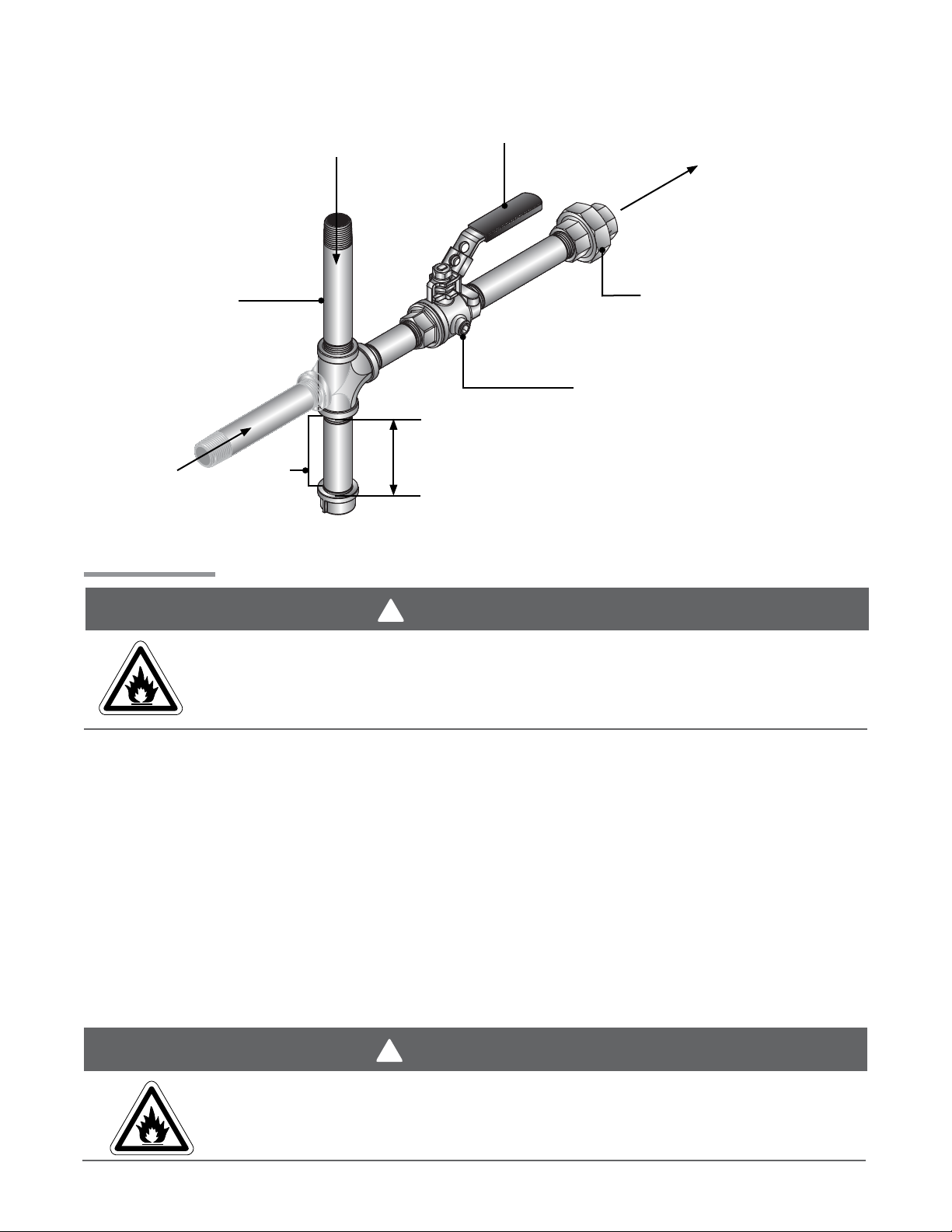
Install a ground joint union with a brass seat and a manual shut off valve adjacent the unit for
emergency shut off and easy servicing of controls. A 1/8” NPT plugged tap that is accessible for a test
gauge connections is also recommended, as illustrated in Figure 3.1.
A sediment trap must be installed in the supply line in the lowest spot prior to connecting to the heater.
The trap length shall be at least three inches long. Ideally, the trap would be installed as close as
possible to the shut off, as shown in Figure 3.1.
16
Page 17
FA Series
!
!
Figure 3.1 • Recommended Hardware – Manual Shut Off and Sediment Trap
3.0 Installation • Gas Supply Installation Instructions • Leak Testing
Gas Supply Line
Leak Testing
Sediment
Trap
Flow of
Gas
Shut Off
To Unit
Ground Joint Union
1/8-in. NPT Test
Connection (Plugged)
3-in.
Minimum
WARNING
Use a soap solution or equivalent for leak testing. Never test for leak with an open
flame. Failure to comply could result in personal injury, property damage or death.
Always leak test final gas assembly for gas leaks according to the procedures outlined in NFPA 54 and
all local codes and/or Standards.
For leak testing on pressures below ½” PSI
Before leak testing, close the field installed manual shut off valve shown on Figure 3.1 on the supply
line to isolate the gas valve from the pressure.
NOTE: All factory installed gas connections have passed an approved leak test.
For leak testing on pressures above ½” PSI
When leak testing with pressures above ½” PSI (14 inches W.C.), the unit must be isolated from the
supply pipe. Close the field installed manual shut off valve, disconnect the supply line to the unit, and
temporarily cap the supply line for testing purposes.
WARNING
Gas pressures to the appliance controls must never exceed 14 inches W.C. (1/2”
PSI). Supply pressures greater than 14” W.C. can damage the controls, resulting in
personal injury, property damage, or death.
17
Page 18
!
3.0 Installation • Electrical Requirements and Wiring Diagrams • Internal Wiring Diagrams
FA Series
Electrical Requirements and Wiring Diagrams
WARNING
Shock hazard. Disconnect power supply before making wiring connections to prevent
electrical shock and equipment damage.
Any original factory wiring that requires replacement must be replaced with wiring
material having a temperature rating of at least 105°C.
All field installed wiring to the unit heater must be done in accordance with national, state, provincial,
local codes and to the guidelines in this manual. In the United States, refer to the most current revisions
to the Electrical Code ANSI/NFPA 70 and in Canada refer to the most current revisions to the Canadian
Electrical Code CSA C22.1 Part 1. The unit must be electrically grounded according to these codes.
Line polarity must be observed when making field connections.
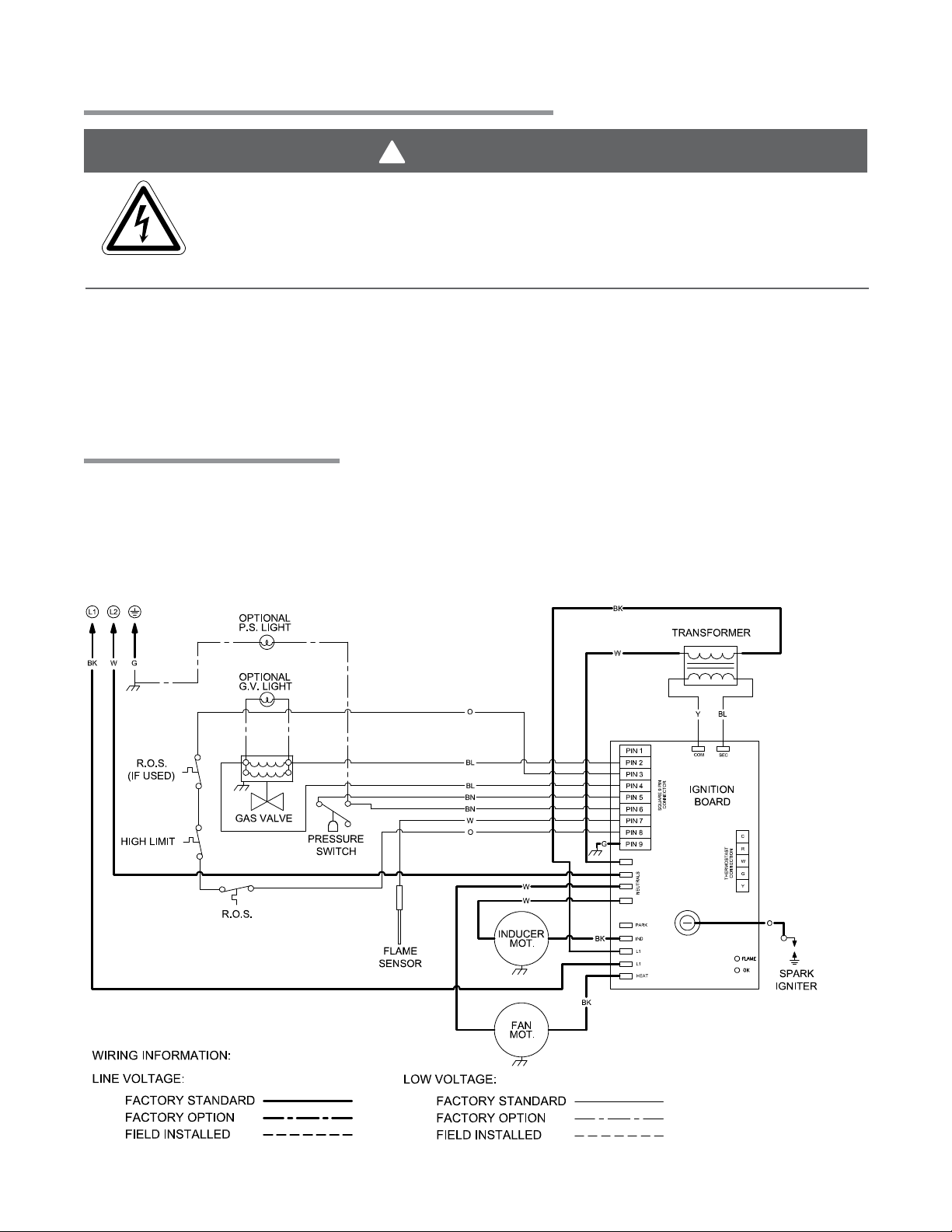
Internal Wiring Diagrams
Before wiring this appliance, check the existing wiring; replace if necessary. If any of the original wire
supplied with the appliance must be replaced, it must be replaced with copper wiring material having a
rating of at least 600V, 105°C.
Figure 3.2 • Internal Wiring Diagram
18
Page 19
FA Series
!
!
3.0 Installation • Field Wiring Supply Voltage
Field Wiring Supply Voltage
Before proceeding with electrical connections, ensure that the supply voltage, frequency, phase and
current capacity meet the requirements specified on the rating plate. A dedicated line voltage supply
with properly sized wire should run directly from the main electrical panel to the heater. The power to
the unit must be protected with a circuit breaker appropriate for the load. The unit must be electrically
grounded in accordance with local codes, or in their absence, with the latest edition of the National
Electrical Code, ANSI / NFPA 70 and/or the Canadian Electrical Code CSA C22.1, latest edition.
CAUTION
The power supply to the heater must be within +/- 5% of the voltage rating as indicated on the rating
plate of the appliance. If input power does not meet these specifications, contact your utility company.
An electrical service disconnect must be provided at the furnace location. A 2 x 4 junction box can be
mounted directly to the unit panel utilizing the provided 1/2” knock-out. If conditions do not allow for this,
locate the service disconnect not more than 5 feet away from the service access panel.
The main electrical supply enters at the rear of the heater utilizing 1/2” electrical knock-out (See Figure
3.3). When routing the electrical supply conduit to the unit, ensure that it does not interfere or obstruct
the heater’s service access panel.
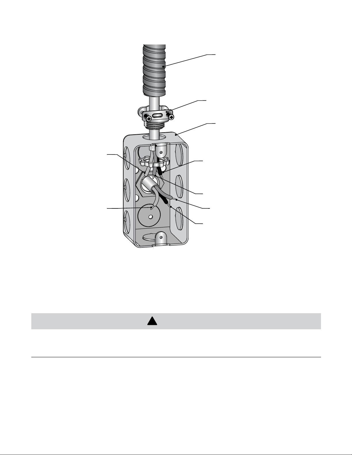
Unit comes with three wire leads to connect the main power supply. Connect the hot, neutral and
ground wires as shown in the field wiring diagram, Figure 3.3. When routing wires through the knockout, use a UL Listed bushing or chase nipple to prevent damage to the wire insulation. When operating
this unit as a sealed combustion appliance, the cabinet opening to the junction box must be sealed air
tight using either a UL approved bushing or a non-reactive UL approved sealant to bushing.
WARNING
Edges of sheet metal holes may be sharp. Use gloves as a precaution when
routing wires.
19
Page 20
!
3.0 Installation • Field Wiring
Figure 3.3 • Field Wiring
L2
FA Series
Flexible Conduit
BX or Romex Connector
Junction Box
L1
Ground
White to L2
(Neutral)
Connect wires together with UL approved wire connectors.
Green to Ground
Black to L1
White to L2
Green
(Ground)
Black to L1
(Hot)
Note: A UL Listed switch may be installed in the 2x4 junction box for use as a service disconnect.
CAUTION
Route the field supplied power wires so that they do not come in contact with the flue wrapper or
venter housing. These hot surfaces may damage the wire’s insulation, resulting in damage to the
unit.
20
Page 21
FA Series
3.0 Installation • Thermostat Connection
Thermostat Connection
NOTE: Different thermostats operate according to their particular features. Refer to the thermostat’s
specifications for details.
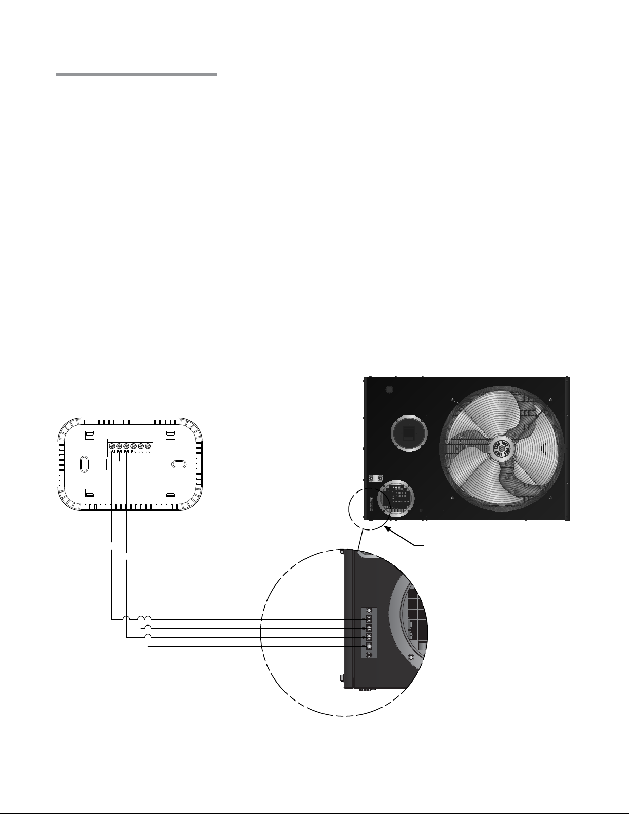
Each FA Series heater requires a single stage thermostat rated for 24VAC to operate. The heater
comes standard with a terminal strip for making the thermostatic connections, located on the back
panel. The thermostat terminal designations are as follows:
R: 24VAC Power
W: Call for Heat
G: Continuous Fan
C: Common for 24VAC Power
24VAC is supplied from an internal 40VA transformer. Do not supply 24 Volts to the terminal strip. A
minimum of 18 AWG low voltage thermostat wire must be used for connecting the thermostat to the
heater. Follow the field wiring diagram in Figure 3.4 for wiring to a typical single-stage thermostat.
Figure 3.4 • Field Wiring Diagram
Thermostat
Rh Rc W Y G C
R
W
G
Y
Heater Back Panel
See Detail A
W RGC
21
Detail A
Page 22

3.0 Installation • Thermostat Location
FA Series
Thermostat Location
The location of the thermostat should be determined by the desired heating requirements and be
mounted on an inside wall five (5) feet above the finished floor. Locate the thermostat in a conspicuous
location, away from where it could be influenced by heat from the unit or other sources, as this may
cause the unit to short cycle. Care should be given to locate the thermostat away from drafts or
frequently opened doors. To prevent drafts inside the wall from affecting the thermostat’s performance,
plug hole for the wire with insulation or suitable caulk. For further information, see the accompanying
instructions with the thermostat.
22
Page 23
FA Series
!
!
!
3.0 Installation • Venting • Replacing Existing Equipment
Venting
The FA Series unit heater must be vented as described here to properly direct the flue gases from the unit
to the outside atmosphere. The venting can terminate vertically through the roof (up) or horizontally
through a sidewall (sideways).
Follow these guidelines and all applicable codes for all models prior to installing the vent material. Local
codes may vary. In the absence of local codes, refer and comply with the National Fuel Code ANSI
Z223.1 (NFPA 54) latest edition or the National Standards of Canada.
WARNING
Gas-fired heaters must be vented. Do not operate unvented.
A built in power exhauster is provided. Additional external
power exhausters are not required or permitted.
Insufficient ventilation and/or improperly sealed vents may
release gas into the building which could result in health problems, carbon monoxide poisoning or death.
Improper venting may result in fire, explosion, injury or death.
All FA Series heaters come with a factory-installed vent and combustion air adapters for attaching vent
pipe to the heater. Attach the venting material to the adapter with three (3) non-corrosive sheet metal
screws. If necessary, drill pilot holes prior to attaching the vent pipe. The venting material must not be
smaller than the factory installed adapter.
WARNING
Do not vent this appliance into another heater’s vents or through a masonry chimney.
Do not use dampers in the heater vent pipe.
Single Wall vent pipe must not pass through any unoccupied attic, inside wall, concealed space, or floor.
Un-insulated single wall vent pipe must not be used outdoors for venting appliances in regions where
winter design temperature is below freezing.
Replacing Existing Equipment
If the unit heater is replacing existing equipment and using an existing vent system, inspect the venting for
proper size and horizontal pitch as directed in these instructions and the latest edition of the National Fuel
Gas Code, ANSI Z223.1 (NFPA 54) or CSA B149.1 Installation Code.
Determine that there is not blockage or restriction, leakage, corrosion or other deficiencies that can cause
hazards. The vent pipe should be corrosion-resistant galvanized steel of a thickness that meets the
National Fuel Gas Code. Minimum thickness for connectors varies depending on the pipe diameter. Never
vent the FA Series with PVC or plastic pipe.
WARNING
If replacing an existing heater, vents may require re-sizing. Improperly sized venting
systems can result in vent gas leakage or condensation. Refer to the National Fuel Gas
Code ANSI Z223.1 (NFPA 54) or CSA B149.1 - latest edition. Failure to follow these
instructions can result in serious injury or death.
23
Page 24

3.0 Installation • General Venting Requirements
FA Series
General Venting Requirements
The venting system for the FA Series heaters may terminate horizontally through a sidewall or vertically
through the roof, and may be individually or commonly vented. Configuration of the vent termination
determines the category type. All model heaters must be installed in accordance to the requirements of
this section, as well as the requirements of its category determination, as described in this manual. To
determine your applications category type, review ‘Vertical Venting’ (Category I) and ‘Horizontal Venting’
(Category III) sections of this manual.
All FA Series Model Requirements:
• Use vent pipe material that is corrosion-resistant galvanized steel of a thickness that meets the
National Fuel Gas Code.
• Do not exceed a maximum vent length of 40 feet.
• Maintain a minimum vent length of 3 feet.
• Maintain a minimum 12 inches of straight pipe from the flue outlet before any directional changes
are made in the venting system.
• Have all vent pipe seams or connectors fastened together with at least three corrosion resistant
sheet metal screws (field supplied).
• Maintain a 6 inch clearance around all single wall vent pipe from any combustible materials. For
double wall vent pipe (type B) follow the vent manufacturer’s clearance to combustibles.
• The equivalent length for a 4 inch 90° elbow is 5 feet.
• The equivalent length for a 6 inch 90° elbow is 7 feet.
• Avoid using more than two 90° directional changes in the venting system.
• Horizontal sections of the vent pipe must be installed with an upward slope from the appliance at a
pitch of ¼ inch per foot.
• Suspend and secure all horizontal runs at points no greater than 3 feet apart.
• Vent termination must maintain a minimum distance of 6 feet from any mechanical air supply inlet.
• Vent must terminate a minimum of 4 feet below, 4 feet horizontally from, or 1 foot above any window
or door that may be opened or gravity air inlet into the building.
• Vent must terminate a minimum of 4 feet above grade level and must extend beyond any
combustible overhang. Vents adjacent to the public walkways must terminate a minimum of 7 feet
above grade level.
• The vent terminal must be installed to prevent any blockage by snow and protect building material
from degradation by flue gases.
• The vent cap must be a minimum of 6 inches from the sidewall of the building.
• Vent must be a minimum of 36 inches below or extend beyond any combustible overhang.
• Consult NFPA ANSI Z223.1 Gas Vent Termination criteria for vents that terminate on a roof pitch that
exceeds 9:12.
• Canada: Vents must terminate a minimum of 3 feet from a window or door that may be opened, and
a non-mechanical air supply inlet or combustion air inlet into the building.
24
Page 25
FA Series
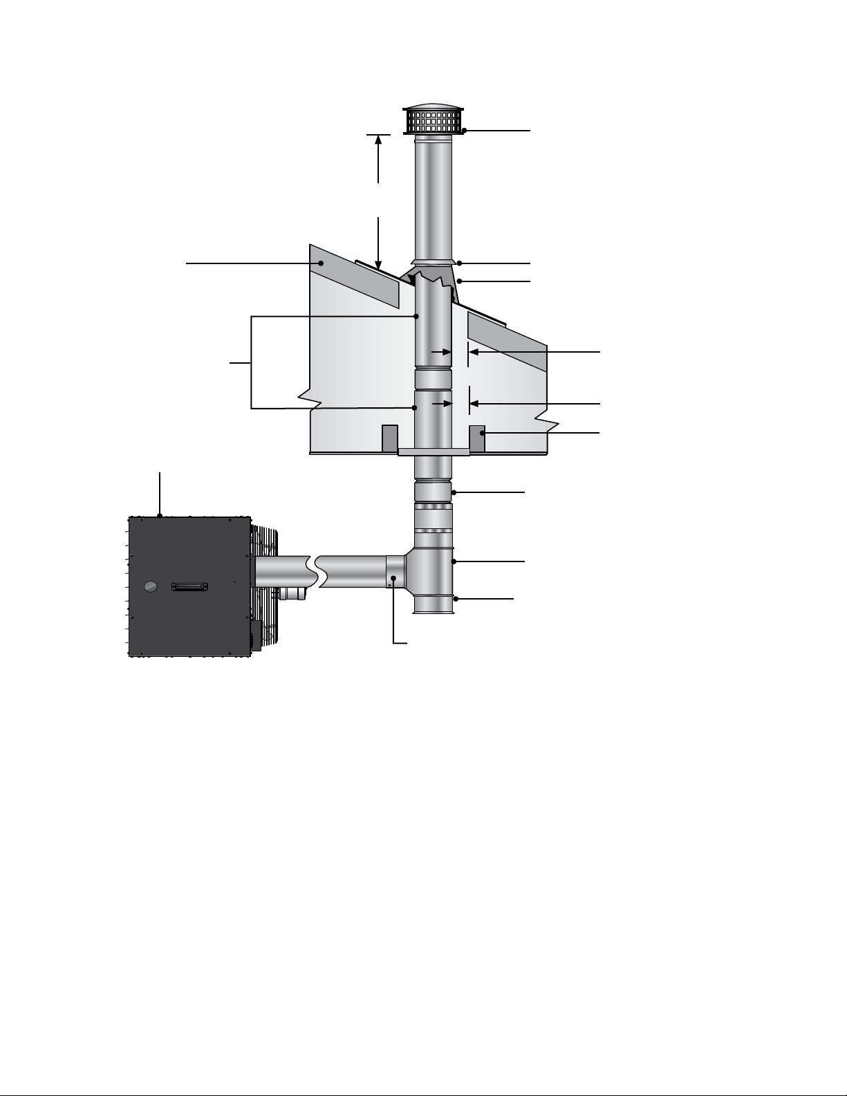
Figure 3.5 • General Vent Requirements
3.0 Installation • General Venting Requirements
Vent Cap
24 in.
Min.*
Roof*
Double-Wall B Vent
Heater
Storm Collar
Adjustable Roof Flashing
1 in. Minimum Clearance
1 in. Minimum Clearance
Fire Stop Spacer
B to C Adapter
Clean Out Tee Fitting
Clean Out Cap
#8 Sheet Metal Screws (field supplied)
*Consult the NFPA ANSI Z223.1 Gas Vent Termination criteria if roof pitch exceeds 9:12
When possible, avoid venting through an unconditioned space. Venting through an unconditioned space
promotes condensation. When venting through an unconditioned space is unavoidable, or if the unit is
installed in an area that is prone to condensation, insulate venting runs greater than 5 feet to minimize the
production of condensation. Inspect for leakage prior to insulating the venting and only use insulation that
is non-combustible with a temperature rating of not less than 400°F. Install a tee fitting at the low point of
the vent system and provide a drip leg with a clean out cap as shown in Figure 3.5.
When venting pipe passes through a combustible interior wall or floor, a metal thimble with a diameter 4
inches greater than the vent pipe diameter must be used. If there is 6 feet or more of vent pipe prior to
passing through the combustible wall or floor, then the metal thimble need only be 2 inches greater than
the vent pipe diameter. If a metal thimble is not used, all clearance to combustibles from the vent pipe
must be 6 inches. Where permitted, type B vent may be used for the last section of vent pipe to reduce
the required clearance to combustibles when passing through a combustible wall or floor. When using
type B venting, follow the manufacturer’s recommended clearance to combustibles. Any material used to
close or insulate the opening must be non-combustible.
25
Page 26

3.0 Installation • Vertical Venting (Category I) • Vent Locations and Clearances
FA Series
Vertical Venting (Category I)
An appliance that operates with a non-positive vent static pressure and with a vent gas temperature that
avoids excessive condensate production in the vent is said to be ‘Category I’. The FA Series heater is
considered a Category I appliance if the venting system meets all of the following criteria:
• The vent system terminates vertically (up).
• The length of the horizontal portion of the vent run is less than 75% of the vertical rise length. (e.g.- If
the vertical vent height is 10 feet, the horizontal run is less than 7-1/2 feet).
• The vent terminates a minimum of 5 feet above the vent connection on the unit.
For vertical vent termination, the venting must comply with all parts of this section, in addition to the
requirements of the general venting.
Category I (Vertical) venting is venting at a non-positive pressure. A furnace vented as a Category I is
considered a fan-assisted appliance and the vent system does not have to be ‘gas tight’. It is
recommended that the venting system is installed with a tee, drip leg, and clean-out cap as shown in
Figure 3.6.
Vent Locations and Clearances:
• Separate air intake duct from vent pipe by a minimum of 4 feet by placing vent pipes higher than
adjacent air intake ducts.
• Utilize a listed type B vent termination cap.
• The vent terminal must extend a minimum of 2 feet above the roof.
• Vent caps should be located a minimum of 2 feet away from adjoining structures.
All vertically vented heaters that are Category I must be connected to a chimney or vent complying with
a recognized Standard, or lined masonry (or concrete) chimney with a material acceptable to the
authority having jurisdiction. Venting into an unlined masonry chimney is not permitted. Refer to the
National Fuel Gas Code and page 24 of this manual.
Use a listed vent terminal to reduce down drafts and moisture in the vent.
26
Page 27
FA Series
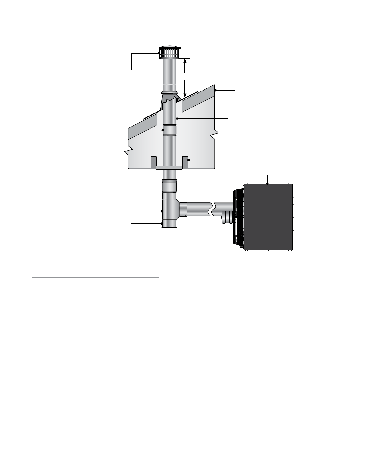
Figure 3.6 • Rooftop Venting - Side View
3.0 Installation • Rooftop Venting • Horizontal Venting (Category III)
Vent Cap
B to C Adapter
Clean Out Tee Fitting
Clean Out Cap
24 in. Min.*
Roof
Double-Wall B-Vent Pipe
Firestop Spacer
Heater
*Consult the NFPA ANSI Z223.1 Gas Vent Termination criteria if roof pitch exceeds 9:12.
Horizontal Venting (Category III)
An appliance that operates with a positive vent static pressure and with a vent gas temperature that
avoids excessive condensate production in the vent is said to be ‘Category III’. The FA Series heater is
considered a Category III appliance if the venting system meets all of the following criteria:
• The vent system terminates horizontally (sideways).
• The vent terminates vertically, but the length of the horizontal portion of the vent run exceeds 75% of
the vertical rise length. (e.g.- If the vertical vent height is 10 feet, the horizontal run is greater than
7-1/2 feet).
• The vent terminates below 5 feet of the vent connection on the unit.
Seal vent pipes with high temperature sealant and three (3) #8 sheet metal screws. Vent enclosed
spaces and buildings according to the guidelines in this manual and applicable national, state,
provincial and local codes.
You may either use an agency certified Category III venting system, or single wall vent pipe with all the
seams and joints sealed with metallic tape or silicone sealant suitable for temperatures up to 400°F.
Wrap the tape two full turns around the vent pipe. For single wall vent systems, one continuous section
of double wall vent pipe may be used with the vent system to pass through a wall or barrier.
All horizontal Category III vents must be terminated with a Simpson-Duravent sidewall vent cap (P/N:
SWD-4 for 4-inch venting or P/N: SWD-6 for 6-inch venting).
27
Page 28
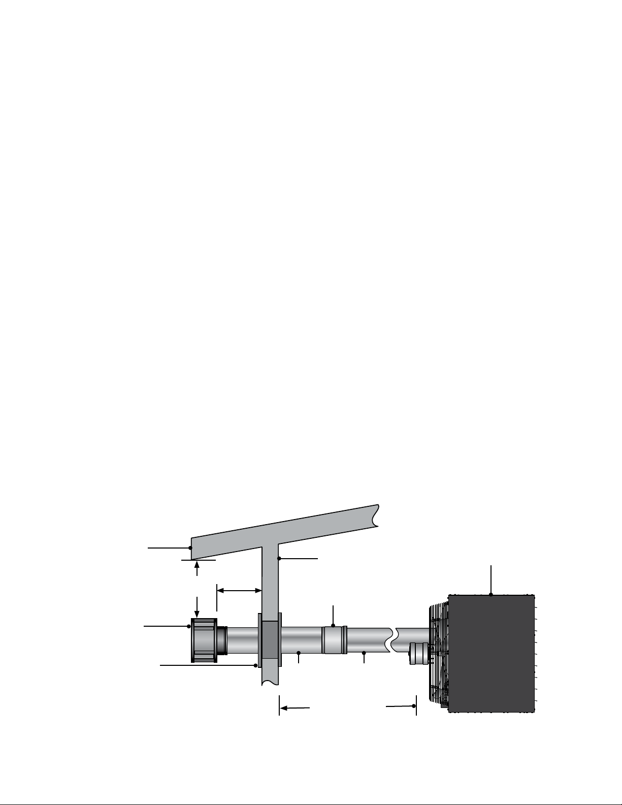
3.0 Installation • Vent Locations and Clearances • Sidewall Venting Requirements
FA Series
Vent Locations and Clearances:
• Category III venting systems may NOT be common vented, and no other gas units are
allowed to be vented into it.
• Vent must terminate a minimum of 4 feet below, 4 feet horizontally from, or 1 foot above any
window or door that may be opened or gravity air inlet into the building.
• Vent must terminate a minimum of 3 feet above any forced air inlet that is located within 10
feet.
• Horizontal venting sections of the vent pipe on a Category III termination must be installed
with a downward slope from the appliance at a pitch of 1/4 inch per foot.
• The bottom of the vent terminate must be located a minimum of 12 inches above grade level
and must extend beyond any combustible overhang. Vents adjacent to public walkways
must terminate a minimum of 7 feet above grade level.
• The vent terminal must be installed to prevent blockage by snow and protect building
materials from degradation by flue gasses.
• The vent cap must be a minimum of 6 inches from the sidewall of the building.
• Vent must be a minimum of 36 inches below or extend beyond any combustible overhang.
• Vents must terminate a minimum of 3 feet from a window or door that may be opened, and a
non-mechanical air supply inlet or combustion air inlet into the building.
• Vents must terminate a minimum of 6 feet from a mechanical air supply inlet.
Never join two sections of double wall vent pipe within one horizontal vent system, as it is
impossible to verify that inner pipes are completely sealed.
Figure 3.7 • Sidewall Venting Requirements
Building Overhang*
36 in.
min.*
6 in.
min.*
Sidewall
B to C Adapter
Heater
Sidewall Vent Cap
Wall Thimble
*Vent must extend beyond any combustible overhang if the vent is less than 36 in. below the combustible overhang.
Double-Wall
B-Vent
1/4 in. downward
pitch per foot
28
Single
Wall Vent
Page 29
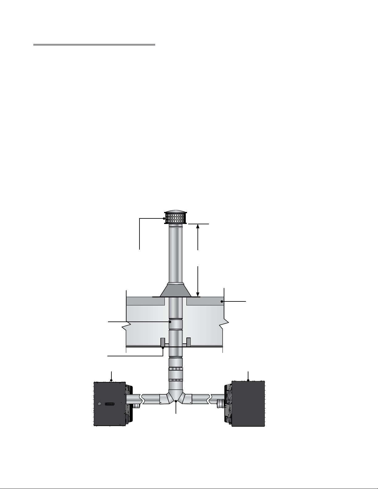
FA Series
3.0 Installation • Common Venting (Category I) • Common Rooftop Venting
Common Venting (Category I)
The common vent system and all attached appliances must be Category I.
The vent connector should be routed in the most direct route from the units to the common vent.
Where two or more vent connectors enter a common gas vent or chimney flue, the smaller
connector shall enter at the highest level consistent with the available head room or clearance to
combustible material.
Restrictions within the common vent such as elbows should be minimized. Each elbow installed
within the common portion of the vent carrying system reduces the maximum common vent
capacity by 10%. Refer to NFPA 54 IFEC tables 11.2 and 11.3 for capacity.
The vent connector capacities allow for the use of two 90° directional changes. For each
additional required elbow, the vent connector capacity is reduced by 10%.
The common vent cross sectional area must be equal to or greater than the largest vent
connector cross sectional area.
Figure 3.8 • Common Rooftop Venting - Side View
Rooftop Vent Cap
Double-Wall B-Vent
Firestop Spacer
Heater
24 in.
M i n .* *
Roof
Heater
Dual Exhaust Assembly
**Consult the NFPA ANSI Z223.1 Gas Vent Termination criteria if roof pitch exceeds 9:12.
29
Page 30
3.0 Installation • Concentric Venting • Combustion Air Requirements
!
FA Series
Concentric Venting
Contact the factory for concentric venting requirements.
Combustion Air Requirements
Combustion air may be supplied to the heater by indoor or outdoor means. Follow these
guidelines and all applicable codes for all models prior to installing the combustion air duct work.
Local codes may vary. In the absence of local codes, refer and comply with the National Fuel
Code ANSI Z223.1 (NFPA 54) latest edition or the National Standards of Canada.
WARNING
Sufficient combustion air must be supplied to the appliance at all times.
Lack of combustion air may result in property damage, serious injury or death.
This unit comes standard equipped for connection of supplied outdoor air for combustion. It is
designed for outside air to be brought into the appliance from combustion intake ducts, and is
referred to as a “Separated Combustion” appliance.
This heater must operate as a separated combustion system if any of the following criteria apply:
• Chemicals such as chlorinated or fluorinated hydrocarbons (typical sources are refrigerants,
solvents, adhesives, degreasers, paints, paint removers, lubricants, pesticides, etc.) are
present in the atmosphere.
• High humidity.
• Contaminants such as sawdust, welding smoke, etc.
• Negative building pressure.
• Unusually tight construction where the air infiltration rate is less than 0.40 air changes per
hour.
If your application does not meet any of these criteria, then room air may be used as supplying
combustion air to the heater. Refer to ‘Room Air Combustion Systems’ on page 33 for details on
how to utilize room air for combustion.
30
Page 31

FA Series
3.0 Installation • Separated Combustion Systems
Separated Combustion Systems
All FA Series heaters come with a factory-installed combustion air adapter for attaching air intake
ducts to the heater. Attach the air intake duct material to the adapter with three (3) non-corrosive
sheet metal screws. If necessary, drill pilot holes prior to attaching the air intake ducts. The
diameter of the intake ducts must not be smaller than the factory installed adapter.
When operating this unit as a separated combustion unit heater system, combustion air must be
supplied to the heater by outdoor means through the factory installed vent connector. The
combustion air intake duct may terminate horizontally through a sidewall or vertically through the
roof. Ideally, the intake should terminate within the same pressure zone as the venting terminates,
which should minimize the effects of wind.
All Separated Combustion systems must comply with the following items:
• Air intake ducts must be of galvanized steel or an equivalent corrosion-resistant material.
• Do not exceed a length of 40 feet.
• Do not exceed more than two (2) 90° directional changes (elbows) in the system.
• Seal all joints with metallic tape or silicone sealant. Wrap the tape two full turns around the
vent pipe.
• Slope air intake pipe ¼ inch per foot upward or downward away from the unit, as shown in
Figure 3.9.
• Do not draw air from attic space.
• Do not draw fresh air from the remaining space around a chimney liner, gas vent, special
gas vent, or plastic piping installed within masonry, metal, or factory built chimney.
• Combustion air ducts may be insulated if they pass through an unconditioned space.
• A factory approved sidewall intake cap must be used when terminating the combustion air
ducts horizontally through the sidewall.
• When combustion air ducts terminate vertically through the roof, a minimum of 18 inches
above the roof grade must be maintained (see Figure 3.10).
• Separate the air intake duct from vent pipe a minimum of 4 feet. Also, place vent pipe higher
than adjacent air intake duct.
• Air intake duct must terminate a minimum of 3 feet below any forced air vent discharge that
is located within 10 feet.
• The bottom of the air intake duct termination must be located a minimum of 12 inches above
grade level. Air intake ducts that terminate adjacent to public walkways must be installed a
minimum of 7 feet above grade level.
• The air intake duct must be installed to prevent blockage by snow, debris, or other possible
obstructions.
31
Page 32
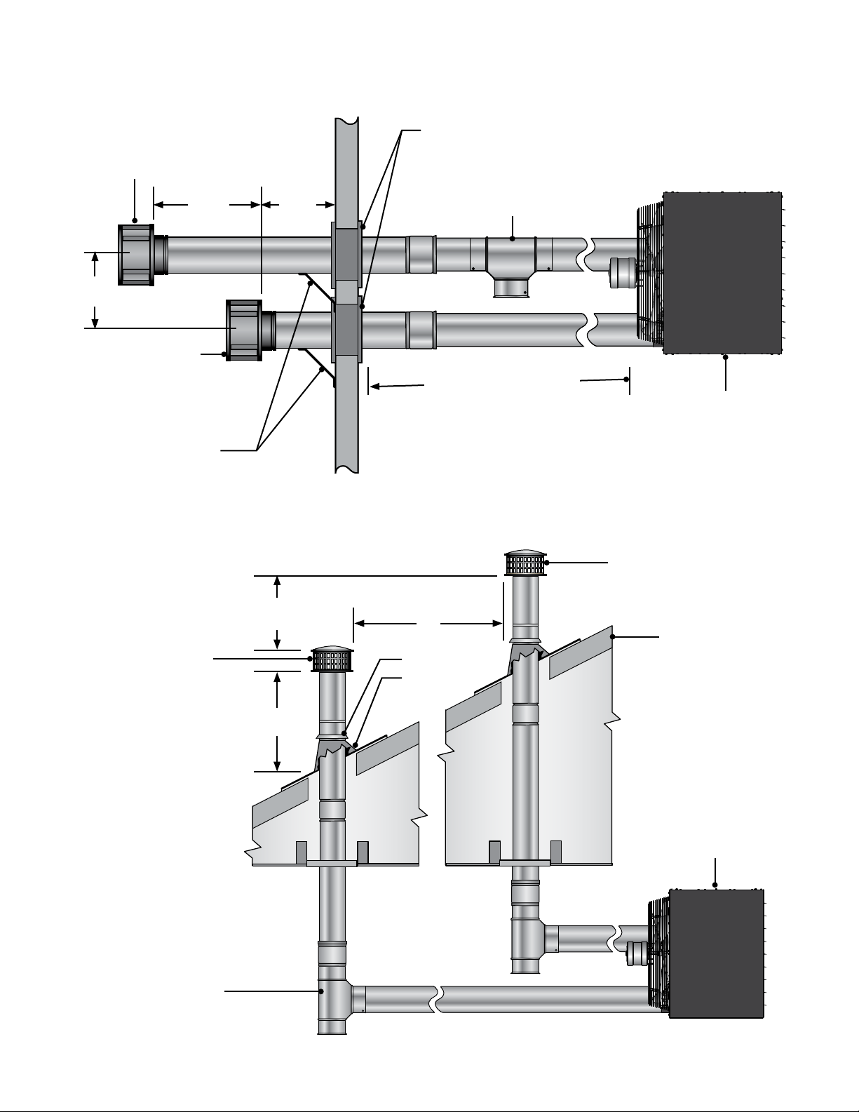
3.0 Installation • Separated Combustion Systems
Figure 3.9 • Outside Combustion Air Sidewall Intake - Side View
Exhaust
Terminal Cap
(P/N: SWD-4
or SWD-6)
3 ft.
Min.
Combustion Air
Intake Cap
(P/N: SWD-4
or SWD-6)
Vent Termination
Support Brackets
12 in.
Min.
6 in.
Min.
Listed Wall Thimble
Clean-out
Tee
1/4 in. pitch per foot
(upward or downward)
Heater
Figure 3.10 • Outside Combustion Air Vertical Intake - Side View
3 ft. Min.
(If X if less than 10 ft.)
Combustion Air
Intake Cap
18 in.
Min.
X
Storm Collar
Listed
Flashing
Listed Exhaust Cap
Roof
Heater
Cleanout Tee
32
Page 33
FA Series
!
3.0 Installation • Room Air Combustion Systems
Room Air Combustion Systems
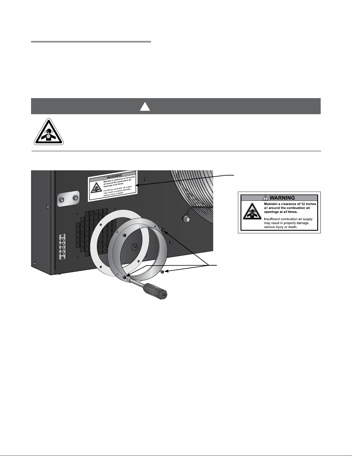
When operating this unit as a room air combustion appliance, the factory installed air intake collar
may be removed and the required air for combustion can be taken into the appliance from the
space, so long as it is not a confined space. (See Figure 3.11)
A “confined space” is defined as a space whose volume is less than 50 cubic feet per 1,000
BTU/h of all the installed heating appliances.
WARNING
Do not draw combustion air from the space if the appliance is located within a confined
space. Insufficient combustion air may result in property damage, serious injury or
death. Use room air for combustion in installations with proper ventilation rates only.
Figure 3.11 • Combustion Air Intake Collar Removal
Affix label (provided in kit) when
using room air for combustion.
F/N: LLUH008
Room Air Warning
Remove air intake collar by
loosening #8 sheet metal screws.
If the combustion air is supplied from indoors, the required volume of the space must be a
minimum of 50 ft3 per 1,000 BTU/h, unless the building is of unusually tight construction. If the
building is of unusually tight construction with air infiltration rates of less than 0.40 air changes per
hour, outside combustion air is typically needed unless the sheer size of the building allows
otherwise. Contact the factory for further determination of the air infiltration rates.
The heater shall be located so as not to interfere with proper circulation of combustion air. A
minimum clearance of 12 inches all around the combustion air openings must be maintained at all
times. Special care should be taken to prevent inadvertent blockage of the combustion air inlet
holes.
Affix warning label adjacent to air intake holes as shown in Figure 3.11 (label is provided in kit). It
is the responsibility of the installer to ensure that there is a minimum 12 inch clearance around the
air intake openings.
33
Page 34
3.0 Installation • Unit Start-Up (Commissioning) • Pre-Start Up Checks
!
!
Unit Start-Up (Commissioning)
WARNING
Improper installation, adjustment, alteration, service or maintenance can cause
property damage, serious injury, or death. This heater must be installed and serviced
by a trained gas installation and service personnel only.
CAUTION
Shock Hazard.
Before attempting to perform any service or maintenance, turn electrical power to
unit OFF at disconnect switch.
Pre-Start Up Checks
FA Series
Verify that the installation conforms to all of the specifications of the manual, as well as with local,
state, national, and provincial codes. In absence of local codes, the unit heater must be installed
according to the current National Fuel Gas Code ANSI Z223.1 (NFPA 54). In Canada, the
installation must conform to the current National Standard of Canada CSA-B149 Sections 1 & 2.
Prior to starting up the unit, verify that:
9 The gas type listed on the rating label matches that of your application.
9 The gas connections have been purged of air and properly leak tested.
9 The voltage type and frequency listed on the rating label matches that of your application.
9 The unit is properly grounded as per the National Electrical Code, ANSI/NFPA 70 or
Canadian Electrical code CSA C22.1 Part 1.
9 The unit is properly mounted to a permanent structure able to bear the weight of the unit.
9 The proper mounting height is observed for the application.
9 All clearance to combustible distances or service clearances are maintained.
9 The unit is properly isolated or installed to prevent excessive vibration.
9 The unit is level horizontally.
9 Venting is properly installed in accordance with this manual and any applicable codes.
9 Combustion air supply is sufficient to support proper operation at all times.
34
Page 35

FA Series
3.0 Installation • Verifying Inlet Pressure
Verify Proper Inlet Pressure
Before starting up the unit, smell all around the unit heater for gas. Be sure to smell next to the
floor because some gas is heavier than air and will settle on the floor.
When turning the gas shut off valve, only use your hand. Never use tools to turn the knobs, as it
may damage the valve resulting in a fire or explosion. If the knob is stuck, do not try to repair it,
contact a qualified service technician or your local gas company.
To verify the proper inlet pressures, follow the following steps:
1 Turn off the gas supply at the manual gas shut off valve.
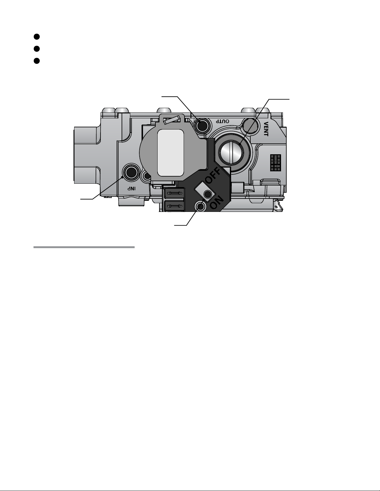
2 Remove the inlet pressure tap plug on the gas control valve (see Figure 3.12).
3 Install a 1/8 inch NPT hose connector and connect the pressure gauge tube.
4 Turn on the gas supply at the manual gas shut off valve.
5 Turn on the electrical power to the unit heater.
6 To light the main burners, set the room thermostat to a point above room temperature.
NOTE: This unit heater is equipped with an ignition device, which automatically lights the
burner. This unit heater cannot be lighted manually. Do not try to light the burner by hand.
Verify
minimum
inlet gas supply pressure:
7 Turn on all other gas appliances that are on the same supply line. If the other gas appliances
have multiple inputs, set it to the maximum rating.
8 Observe the pressure rating on the pressure gauge.
The minimum inlet gas supply pressure for:
• Natural gas is 5.0 inches W.C.
• Propane gas is 11.0 inches W.C.
Verify
maximum
inlet gas supply pressure:
9 Turn off all other gas appliances on the same supply line.
10
Observe the pressure reading on the pressure gauge.
The maximum inlet gas supply pressure for:
• Natural gas is 14.0 inches W.C.
• Propane gas is 14.0 inches W.C.
IMPORTANT: If the inlet gas supply pressure is not within the minimum and maximum
range as shown on the rating plate, contact your gas supplier.
Removing pressure gauge from inlet port on gas valve.
Set thermostat or other control device to the lowest set point.
11
After heater has completed the post-purge cycle, turn off the electrical power to the unit
heater.
12
Turn off the gas supply at the manual gas shut off valve.
35
Page 36
3.0 Installation • Verifying Manifold Pressure
13
Remove the pressure gauge tube and the 1/8 inch NPT hose connector.
14
Replace the inlet pressure tap plug on the gas control valve.
15
Leak check the re-installed pressure tap plug using a soap solution or equivalent method
FA Series
as described in ANSI Z223.1 (NFPA 54).
Figure 3.12 • Gas Valve Shown in ON Position
Manifold Pressure Outlet
Inlet
Pressure Port
On/Off Switch
Manifold Pressure
Adjustment Screw
(under cap)
Verify Manifold Pressure
Before starting up the unit, smell all around the unit heater for gas. Be sure to smell next to the
floor because some gas is heavier than air and will settle on the floor.
When turning the gas shut off valve, only use your hand. Never use tools to turn the knobs, as it
may damage the valve resulting in a fire or explosion. If the knob is stuck, do not try to repair it,
contact a qualified service technician or your local gas company.
To verify the proper manifold pressure, follow the following steps:
1 Turn off the gas valve with the switch located on the valve body (see Figure 3.12).
2 Remove the manifold pressure tap plug on the gas control valve (see Figure 3.12).
3 Connect the pressure gauge tube and manometer.
4 Turn on the gas valve with the switch located on the valve body.
5 Turn on the electrical power to the unit heater.
6 To light the main burners, set the room thermostat to a point above room temperature.
NOTE: This unit heater is equipped with an ignition device, which automatically lights the
burner. This unit heater cannot be lighted manually. Do not try to light the burner by hand.
Verify manifold pressure:
7 After the unit has successfully ignited, wait five minutes prior to taking any readings. The
unit heater must be in a steady state of operation prior to taking a manifold pressure reading.
36
Page 37

FA Series
3.0 Installation • Prior to Leaving the Job Site
8 While waiting for the unit to stabilize, observe the characteristics of the flame. The flame
should be stable and should not lift form any burner. The burner color should be light blue,
and not create excessive noise.
9 After five minutes, observe the pressure rating on the pressure gauge.
The target manifold gas supply pressure for:
• Natural gas is 3.5 inches W.C.
• Propane gas is 10.0 inches W.C.
NOTE: Manifold pressure of the heater is pre-set at the factory. No adjustment should be
necessary.
During the verification process, a tolerance of +/- 5% of the full scale is acceptable due to varying
atmospheric conditions.
If manifold pressure is outside of this tolerance, then an adjustment may be necessary.
Removing pressure gauge from manifold port on gas valve:
10
Set thermostat or other control device to the lowest set point.
11
After heater has completed the post-purge cycle, turn off the electrical power to the unit
heater.
12
Turn off the gas valve with the switch located on the valve body (see Figure 3.12).
13
Remove the pressure gauge tube and the manometer.
14
Replace the manifold pressure tap plug on the gas control valve.
15
Leak check the re-installed pressure tap plug using a soap solution or equivalent method
as described in ANSI Z223.1 (NFPA 54).
Prior to leaving the Job Site
Prior to leaving the job site, verify that:
9 Service access door is properly secured to the unit with the sight glass aligned with the
burner side.
9 The heater is clear of any objects that would interfere with the proper air circulation or that
violate the listed clearance to combustibles.
9 Air directional louvers are adjusted for desired air flow and are not shut or adjusted beyond
60° from perpendicular to the face of the unit.
9 Manual gas shut off is ON.
9 Electrical power is ON.
9 Thermostat is set to desired temperature.
9 Properly dispose of all packaging materials.
9 Check to be sure you have all of your tools.
9 Leave the Installation, Operation, Maintenance and Parts Manual with the owner or end user.
37
Page 38
!
3.0 Installation • High Altitude Operation
FA Series
High Altitude Operation
WARNING
Explosion hazard. This heater must be converted by a trained gas installation and
service personnel only. Failure to comply could result in personal injury, asphyxiation,
death, and fire or property damage.
The FA Series heater is factory configured for altitudes from 0 – 2,000 ft above sea level. If the
unit heater is being installed at an elevation above 2,000 ft, the input rate will have to be de-rated
to ensure proper operation. The deration is achieved by a gas orifice change.
The installation of the high altitude orifices must be done prior to putting the heater in operation
and prior to connecting the gas supply line. The manifold pressure may need to be re-adjusted
after orifices are installed. Refer to Charts 3.5 through 3.7 for proper high altitude conversion kit.
For altitudes above 9,500 feet, consult factory.
High Altitude Conversion Kit Installation:
Remove service access door by unscrewing the 5/16” (#10) sheet metal screws securing the door.
1
Disconnect all wires connecting to the gas control valve.
2
Remove the manifold pipe from the burner assembly by removing the four mounting screws.
3
Slide the manifold pipe assembly out of the control compartment.
4
Remove gas orifices from the manifold using a 7/16” wrench.
5
Thread in the new orifices of the correct kit, starting threads by hand. Take care not to cross thread
6
the orifices (See C
Tighten gas orifices to a torque of 150 inch pounds. No thread sealant is necessary, as the brass is
7
designed to seal to the steel manifold pipe at the proper torque.
Inspect all the newly installed orifices to ensure they are straight and aligned 90° to the manifold
8
pipe. Correct or replace any misaligned orifices.
Reinstall the manifold pipe assembly to the unit, ensuring that each orifice is properly aligned with
9
the burners. Secure with four 5/16” (#10) screws.
10
Reconnect all wires to the gas control valve.
11
Proceed with the installation of the gas supply line as described within this manual.
Chart 3.5 • High Altitude Conversion Kits for Elevations of 2,000 to 4,500 Feet
Model
FA-100
FA-12 5
FA-15 0
FA-175
FA-200
FA-225
FA-250
harts 3.5 through 3.7 for proper kit number and orifice size).
Number of
Orifices
4 HKN-43_4 HKP-55_4 43 DMS 55 DMS
5 HKN-43_5 HKP-55_5 43 DMS 55 DMS
6 HKN-43_6 HKP-55_6 43 DMS 55 DMS
7 HKN-43_7 HKP-55_7 43 DMS 55 DMS
7 HKN-41_7 HKP-54_7 41 DMS 54 DMS
9 HKN-43_9 HKP-55_9 43 DMS 55 DMS
9 HKN-42_9 HKP-54_9 42 DMS 54 DMS
Natural Gas Propane Natural Gas Propane
Kit Number Orifice Size
38
Page 39
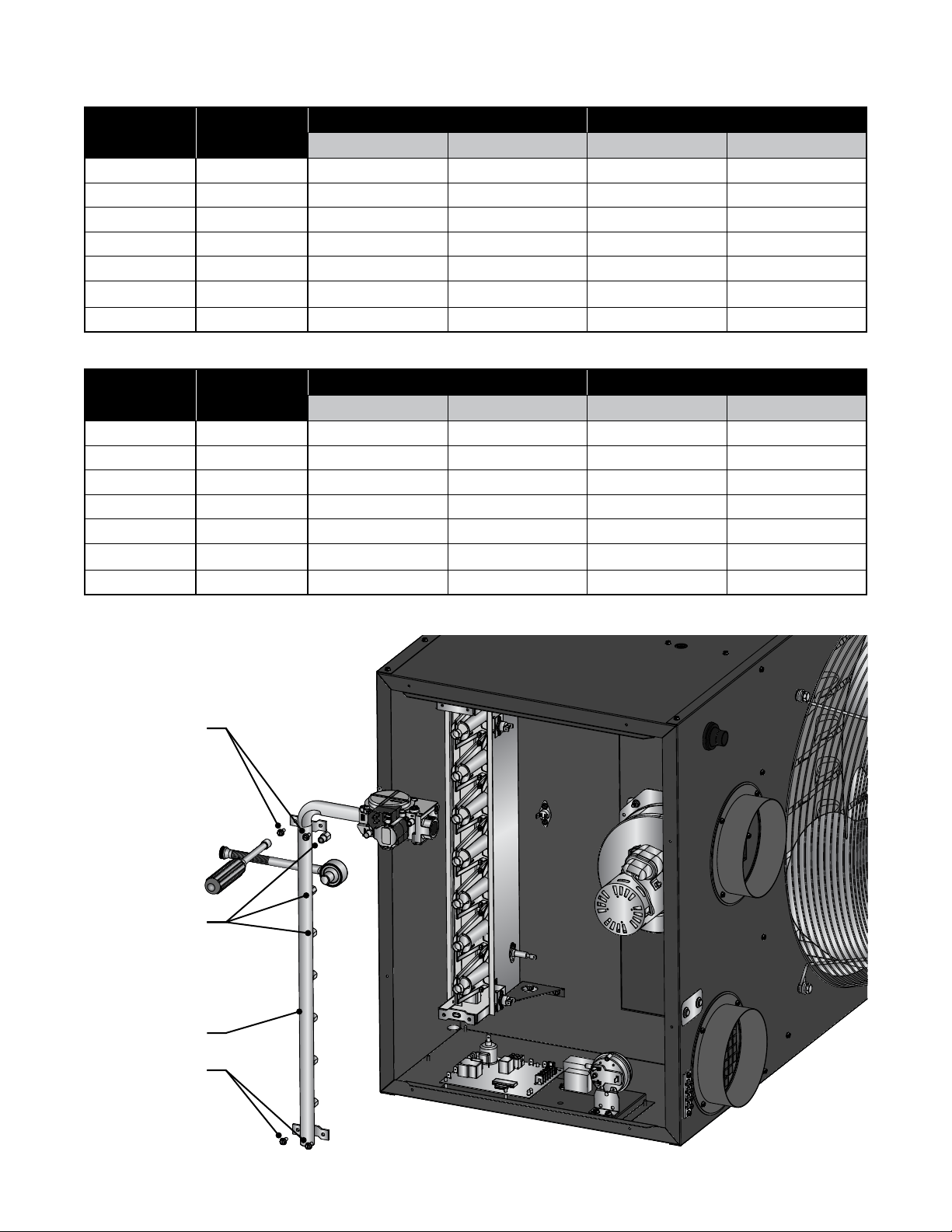
FA Series
3.0 Installation • High Altitude Operation
Chart 3.6 • High Altitude Conversion Kits for Elevations of 4,501 to 7,000 Feet
Kit Number Orifice Size
Model
FA-100
FA-12 5
FA-15 0
FA-175
FA-200
FA-225
FA-250
Number of
Orifices
4 HKN-44_4 HKP-55_4 44 DMS 55 DMS
5 HKN-44_5 HKP-55_5 44 DMS 55 DMS
6 HKN-44_6 HKP-55_6 44 DMS 55 DMS
7 HKN-44_7 HKP-55_7 44 DMS 55 DMS
7 HKN-43_7 HKP-54_7 43 DMS 54 DMS
9 HKN-44_9 HKP-55_9 44 DMS 55 DMS
9 HKN-42_9 HKP-54_9 42 DMS 54 DMS
Natural Gas Propane Natural Gas Propane
Chart 3.7 • High Altitude Conversion Kits for Elevations of 7,001 to 9,500 Feet
Kit Number Orifice Size
Model
FA-100
FA-12 5
FA-15 0
FA-175
FA-200
FA-225
FA-250
Number of
Orifices
4 HKN-45_4 HKN-56_4 45 DMS 56 DMS
5 HKN-45_5 HKN-56_5 45 DMS 56 DMS
6 HKN-45_6 HKN-56_6 45 DMS 56 DMS
7 HKN-45_7 HKN-56_7 45 DMS 56 DMS
7 HKN-44_7 HKN-55_7 44 DMS 55 DMS
9 HKN-45_9 HKN-56_9 45 DMS 56 DMS
9 HKN-43_9 HKN-55_9 43 DMS 55 DMS
Natural Gas Propane Natural Gas Propane
Figure 3.13 •
Sheet Metal
Gas Orifices
Note: Install gas
orifices to a torque
of 150 in. lbs.
Manifold Pipe
Sheet Metal
High Altitude Kit Installation
Screws
Screws
39
Page 40
4.0 Operation • Sequence of Operation
!
!
FA Series
4.0 Operation
WARNING
This appliance does not have a pilot ignition. It is equipped with an ignition device
which automatically lights the burner. Do not attempt to light the system by hand.
Sequence of Operation
Standby: The ignition control continually checks for internal faults, circuit integrity and relay contact
positioning. The LED is lit indicating power is applied.
Starting Circuit: Upon a call for heat, the control verifies that the limit switch is closed and the
differential pressure switch is in the open position. The control energizes the induced draft motor. Once
operational static pressure is achieved the differential switch will close initiating the ignition sequence.
The control energizes the spark and main gas valve for 10 seconds. If the flame is not sensed, the
control will attempt to re-ignite for a total of (3) tries for ignition before proceeding to soft lockout.
Running Circuit: After ignition, the flame rod monitors burner flame. If flame sense is not established
within 10 seconds, the control will attempt two (2) additional ignition sequences before proceeding to
soft lockout. The control can be reset by briefly interrupting the power source. If flame is sensed the
control waits for a 30 second heat blower on delay and then energizes the indoor blower, the control
proceeds to steady heat mode. If sense of flame is lost, the control closes the gas valve within 1
second and a new trial sequence (identical to the starting sequence) is initiated.
Shut Down: When the thermostat is satisfied, the control closes the valve and the induced draft motor
remains on for a 5 second post-purge period. The indoor blower is de-energized after 120 seconds.
WARNING
Use only your hand to turn the manual shut off. Never use tools. If the
knob will not turn by hand, don’t try to repair it; call a qualified technician.
Force or attempted repair may result in a fire or explosion.
40
Page 41
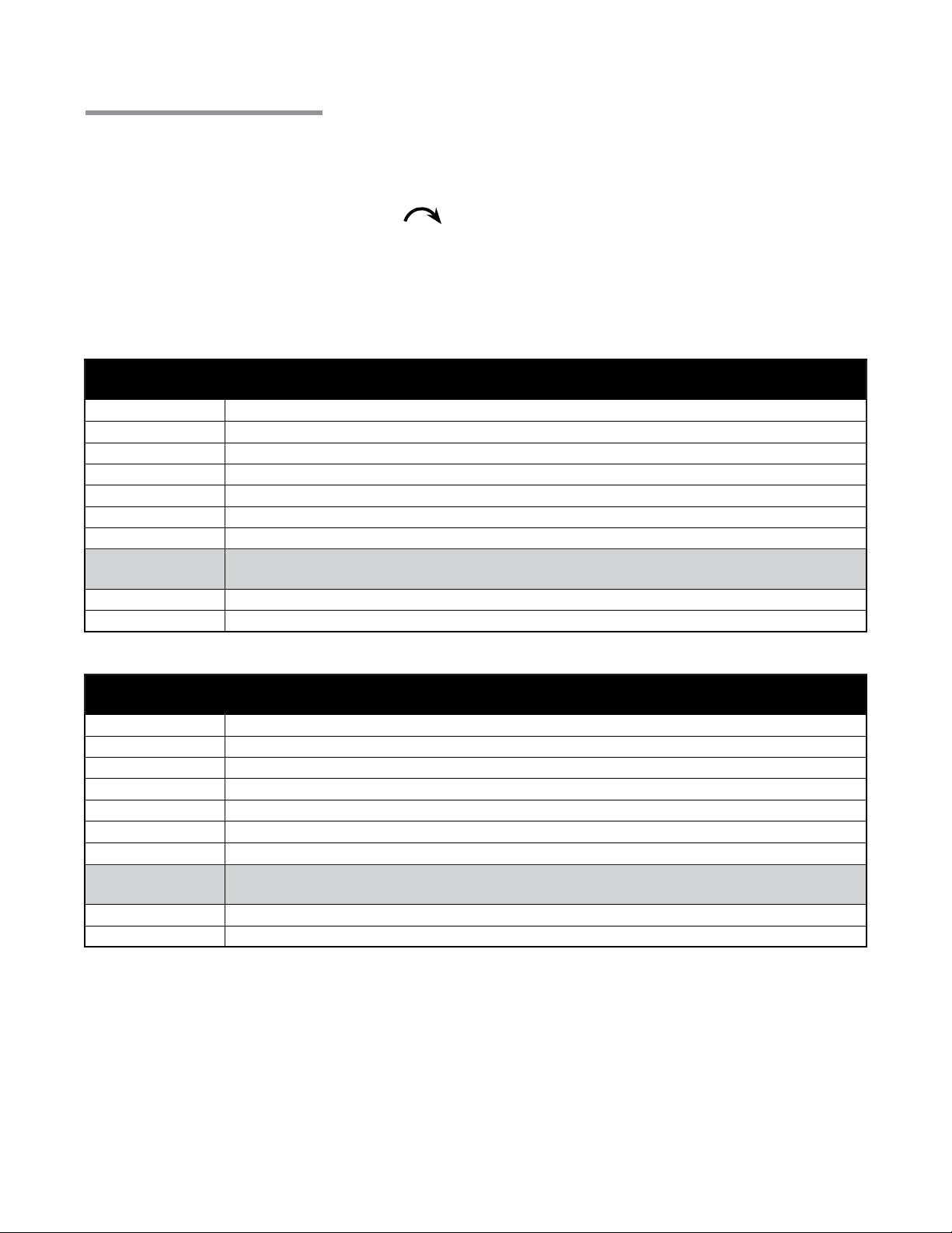
FA Series
4.0 Operation • Shutdown Procedures
Shutdown Procedures:
Set the thermostat to the lowest setting.
Turn OFF all electrical power to the appliance if service is to be performed.
Turn manual shut off knob clockwise to OFF. Do not force.
If the heater’s internal diagnostic LED displays any of the signals listed in Charts 4.1-4.2, address the
indicated problem as outlined.
Chart 4.1 • LED Diagnostic Codes - United Technologies Circuit Board
LED CODE
(# of flashes)
STEADY OFF Internal Control Fault or No Power
STEADY ON Control Ok
1 In Lockout from Failed Ignitions or Flame Losses
2 Pressure Switch Open with Inducer ON
3 Pressure Switch Closed with Inducer OFF
4 Limit Switch is OPEN
5 In Lockout from False Flame
LED CODE
(# of flashes)
FAST FLASH Flame Present With Gas Valve Off
STEADY ON Flame is Sensed
GREEN LED STATUS / ERROR
AMBER LED STATUS / ERROR
Chart 4.2 • LED Diagnostic Codes - Fenwal Circuit Board
LED CODE
(# of flashes)
SLOW FLASH Normal Operation - No Call for Heat
FAST FLASH Normal Operation - Call for Heat
2 Ignition Lockout - No Flame Detected
3 Airflow Fault - Pressure Switch Open or Closed
4 High Limit or Rollout Switch Open
5 Flame Sense Error - Gas Valve Not Energized
STEADY ON Internal Control Failure
LED CODE
(# of flashes)
OFF Flame Signal is Below Required Level / No Flame Present
STEADY ON Flame is Sensed
GREEN LED STATUS / ERROR
AMBER LED STATUS / ERROR
41
Page 42
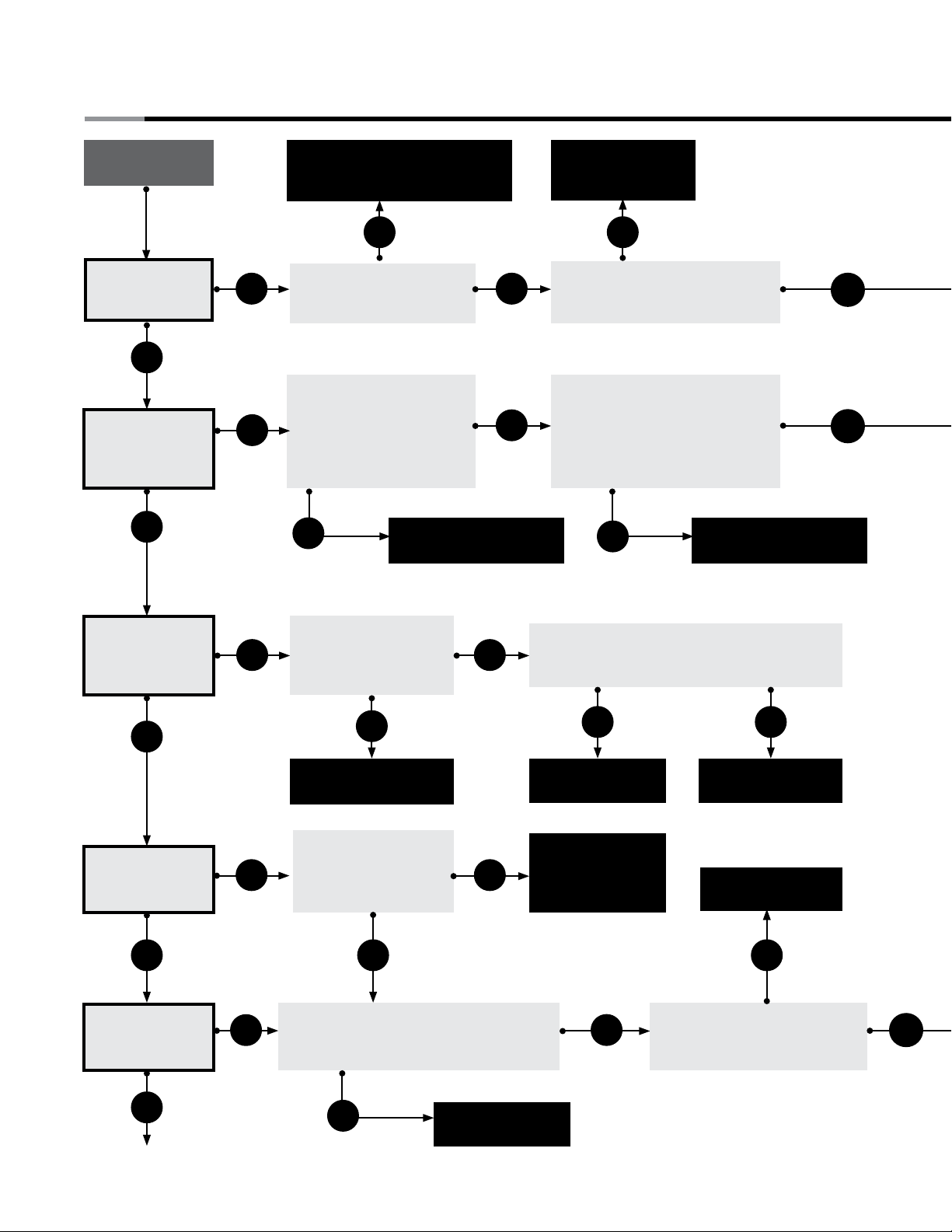
4.0 Troubleshooting Guide
4.0 Troubleshooting Guide
FA Series
Turn on control
device for heat.
Does the draft
inducer motor
turn on?
Yes
Does the
pressure switch
indicator light
turn on?
Yes
No
No
Limit switch is open or pressure
switch is stuck closed. Find
faulty switch and repair.
Does the air circulating
fan turn on immediately?
Is the inlet or outlet of the
heater obstructed, or is
the vent exceeding the
recommended lengths?
Yes
Remove obstruction or
correct vent lengths.
No
No
Find source of
electrical problem.
NoYes
Does the heater have 120 VAC
at the main power connection?
Check for loose wiring or
restrictions in the hose
connection to the pressure
switch. Are they acceptable?
No
Replace wiring or hose
connections.
Yes
Yes
Does the circuit
board send
spark to the
electrode?
Yes
Does the valve
indicator light
turn on?
Yes
Does the gas
valve turn on?
No
No
No
Does the electrode
appear to be
physically damaged?
No
Yes
Replace igniter.
Does the gas valve
turn on? Do you see
the burners in the
sight glass?
Yes
No
Check inlet pressure to the heater. Is
it within the minimum and maximum
allowable range as per the rating plate?
Temporarily disconnect the igniter wire
from the circuit board and check for
continuity. Is there continuity?
YesNo
Replace wire.
Gas valve
indicator light is
burned out.
Replace light.
Replace circuit
board.
Correct wiring.
No
Yes
Are the wires to and from the
gas valve properly connected?
Yes
Yes
Continued on page 44.
No
Adjust inlet
pressure.
42
Page 43
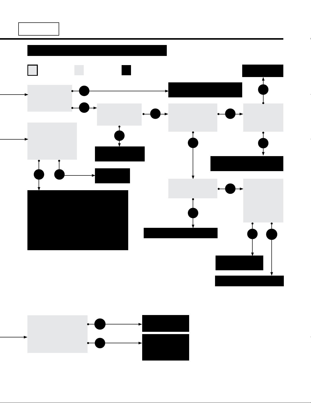
FA Series
4.0 Troubleshooting Guide
NOTICE
during normal operation or the heater’s built-in safety mechanisms will be compromised.
Key
Bypassing any switch is intended for testing purposes only. Do not leave switch bypassed
Start
Question
Is there 24 VAC
across the ‘R’ and
‘C’ terminals?
After approx.
10 seconds of
operation, is there
a flash code for
‘Pressure Switch
Failure’?
No
Replace pressure switch after verifying:
• Heater, blower, and venting are clean and
free of obstructions.
• The allowable vent length is not
exceeded.
• There is not a negative pressure
experienced at the area of intake (e.g.,
high winds, attic space, tightly sealed
building).
Yes
Process
Question
No
Yes
and ‘C’ terminals?
Repair thermostat or
circuit board.
Is there 24 VAC
across the ‘W’
No
thermostat wiring.
Replace
Corrective
Action
Yes
Check fuse on circuit board and
internal controls transformer.
Is the circuit board
sending 120 VAC
to the draft inducer
motor?
No
Is the pressure
switch stuck in the
closed position?
Yes
Pressure switch is faulty.
Remove
obstruction.
Yes
Yes
Is the draft
inducer impeller
obstructed or
locked up?
No
The draft inducer motor is
faulty and must be replaced.
No
Check the
two flame roll
out switches
and the tube
temperature
limit switch. Are
they closed?
No
Yes
Monitor the voltage on
the gas valve terminals
during trial for ignition.
Is there 24 VAC present
during the spark
sequence?
Yes
No
Reset or replace
faulty limit switch.
Replace circuit board.
Gas valve is faulty.
Replace.
Check for flash
codes on the circuit
board. Replace the
ignition module.
43
Page 44
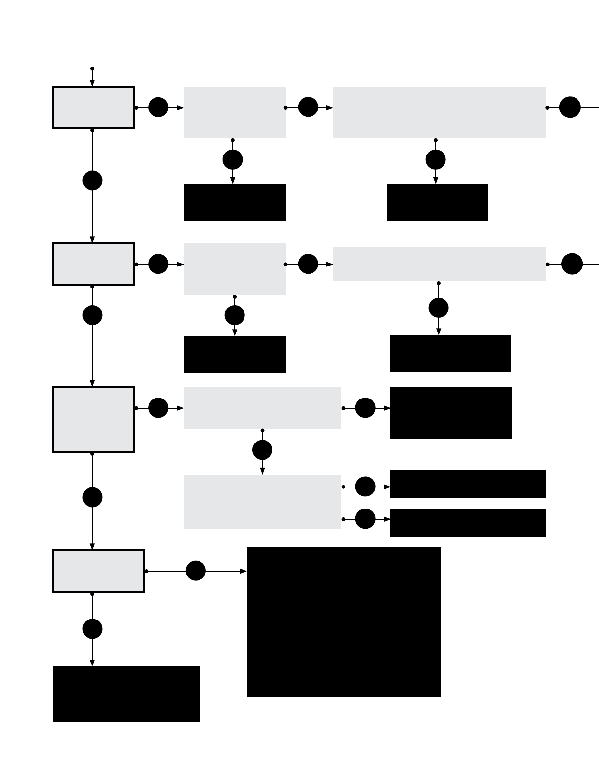
4.0 Troubleshooting Guide
Continued from page 42.
FA Series
Do the burners
ignite?
Yes
Do the burners
stay lit?
Yes
No
No
Is the gas supply
valve to the heater in
the “on” position?
No
Turn on gas supply
line.
Do the burners light
and then shut off
immediately (within
1-2 seconds)?
Yes
Check inlet pressure
and limit switches.
Yes
No
Check inlet pressure to the heater. Is it within
the minimum and maximum allowable range
as per the rating plate?
No
Adjust inlet pressure.
Does the burner stay on for approximately
8-10 seconds, and then shut off?
No
Check circuit board for
flash codes. Consult
factory.
Yes
Yes
Does the air
motor fan turn
on approx. 30
seconds after
ignition?
No
Yes
Does the heater
stay on until the
call for heat ends?
Yes
Troubleshooting ends.
For more information, contact
your local representative or the
factory for further assistance.
Does the circuit board send 120
VAC to the air movement fan after
approx. 30 seconds after ignition?
Yes
Is the motor dirty, obstructed, or
damaged, inhibiting rotation?
No
The heater can shut down or stay on due to:
• Limit switch opening.
• Pressure switch opening.
• Improper grounding.
• Faulty control device.
• High winds.
• Taking combustion air from the attic.
• Dirty environment.
• Fluctuating gas pressure.
No
No
Yes
Verify wires are not
damaged. Check flash
codes, and then replace
circuit board.
Check motor starter capacitor.
Replace or repair.
Clean fan, remove obstruction, or
replace damaged parts.
44
Page 45
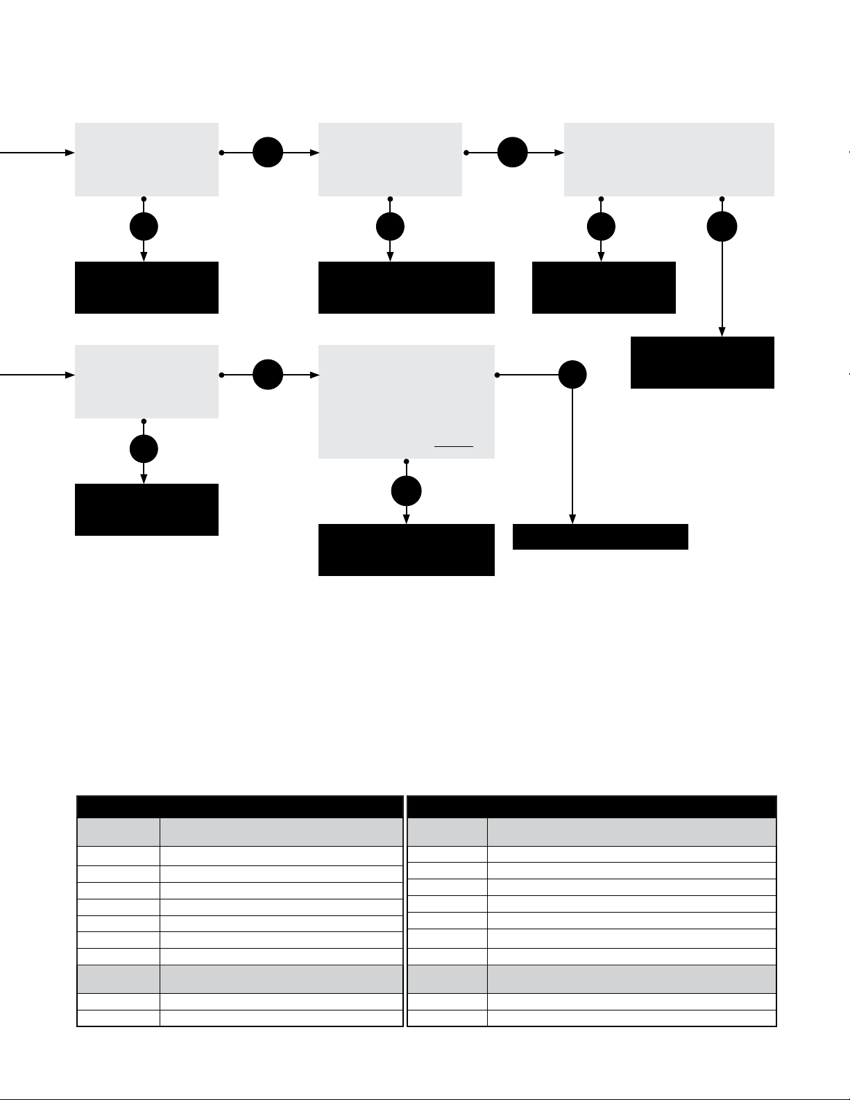
FA Series
4.0 Troubleshooting Guide
Were the gas lines
purged of all air?
No
Purge gas lines.
Is the heater properly
grounded? Is the
heater’s polarity
correct?
No
Correct grounding or
fix polarit y.
Yes
Yes
Does the heater’s gas
type match the gas
supplied?
No
Contact local
representative or factory.
With a micro ammeter,
check micro-Amp reading
of flame sensor circuit. Is
it greater than 0.5 micro-
Amps? NOTE: Meter must
be connected in series.
Yes
Check circuit board flash
codes. Replace ignition
module.
Yes
Adjust pressure or
replace gas valve.
No
Replace circuit board.
Check manifold pressure. Are
you reading within the specified
pressures per the rating plate?
No
Yes
Check circuit board
for flash codes.
Consult factory.
LED Diagnostic Codes
United Technologies Circuit Board
LED CODE
(# of flashes)
STEADY OFF Internal Control Fault or No Power
STEADY ON Control Ok
1 In Lockout from Failed Ignitions or Flame Losses
2 Pressure Switch Open with Inducer ON
3 Pressure Switch Closed with Inducer OFF
4 Limit Switch is OPEN
5 In Lockout from False Flame
LED CODE
(# of flashes)
FAST FLASH Flame Present With Gas Valve Off
STEADY ON Flame is Sensed
GREEN LED STATUS / ERROR
AMBER LED STATUS / ERROR
Fenwal Circuit Board
LED CODE
(# of flashes)
SLOW FLASH Normal Operation - No Call for Heat
FAST FLASH Normal Operation - Call for Heat
2 Ignition Lockout - No Flame Detected
3 Airflow Fault - Pressure Switch Open or Closed
4 High Limit or Rollout Switch Open
5 Flame Sense Error - Gas Valve Not Energized
STEADY ON Internal Control Failure
LED CODE
(# of flashes)
STEADY ON Flame is Sensed
OFF Flame Signal is Below Required Level / No Flame Present
GREEN LED STATUS / ERROR
AMBER LED STATUS / ERROR
45
Page 46

5.0 Maintenance
FA Series
5.0 Maintenance
To check gas tightness of the safety shut off valves, turn off the manual valve upstream of the appliance
combination control. Remove the hex head plug on the inlet side of the combination control and
connect a manometer to that tapping.
Turn the manual valve on to apply pressure to the combination control. Note the pressure reading on
the manometer, then turn the valve off. Any loss of pressure indicates a leak. If a leak is detected, use a
soap solution to check all threaded connections. If no leak is found, combination control is faulty and
must be replaced before putting appliance back in service.
Should maintenance be required, perform the following inspection and service routine:
Inspect the area near the unit to be sure that there is no combustible material located within the
1
minimum clearance requirements listed in this manual. Under no circumstances should combustible
material be located within the clearances specified in this manual. Failure to provide proper
clearance could result in personal injury or equipment damage from fire.
Turn off the manual gas valve and electrical power to the unit heater. Remove service access panel.
2
To clean or replace the burner, remove retainer from around manifold orifice, disconnect flame
3
sensor and igniter from control board, remove burner assembly mounting screws. With the burner
removed, wire brush the inside surfaces of the heat exchanger.
Remove any dirt, dust, or other foreign matter from the burners using a wire brush or compressed
4
air. Ensure that all parts are unobstructed. Then reassemble the unit heater by replacing all parts in
reverse order.
Complete the appropriate unit startup procedure as given in the Operation section of this Manual.
5
(See lighting instructions on the unit nameplate.)
• Check the burner adjustment.
• Also check all gas control valves and pipe connections for leaks.
Check the operation of the automatic gas valve by lowering the setting of the thermostat, stopping
6
the operation of the gas unit heater. The gas valve should close tightly, completely extinguishing the
flame on the burner.
Inspect and service motor/fan assembly. To maintain efficient air flow, inspect and clean the fan
7
blades and guard to prevent buildup of foreign matter.
If combustion air is room supplied, ensure that a 12 inch clearance is maintained all around the inlet
8
openings.
46
Page 47
FA Series
Check lubrication instructions on motor. If oiling is required, add three or four drops of SAE 20 electric
9
motor oil:
• After three years or 25,000 hours (for light-duty operation).
• Annually after three years or 8,000 hours (for medium-duty operation).
• Annually after one year or 1,500 hours (for heavy-duty operation).
5.0 Maintenance
NOTICE
Never over-oil the motor, or premature failure may occur.
10
Check and test functions of all safety devices supplied with the heater.
47
Page 48
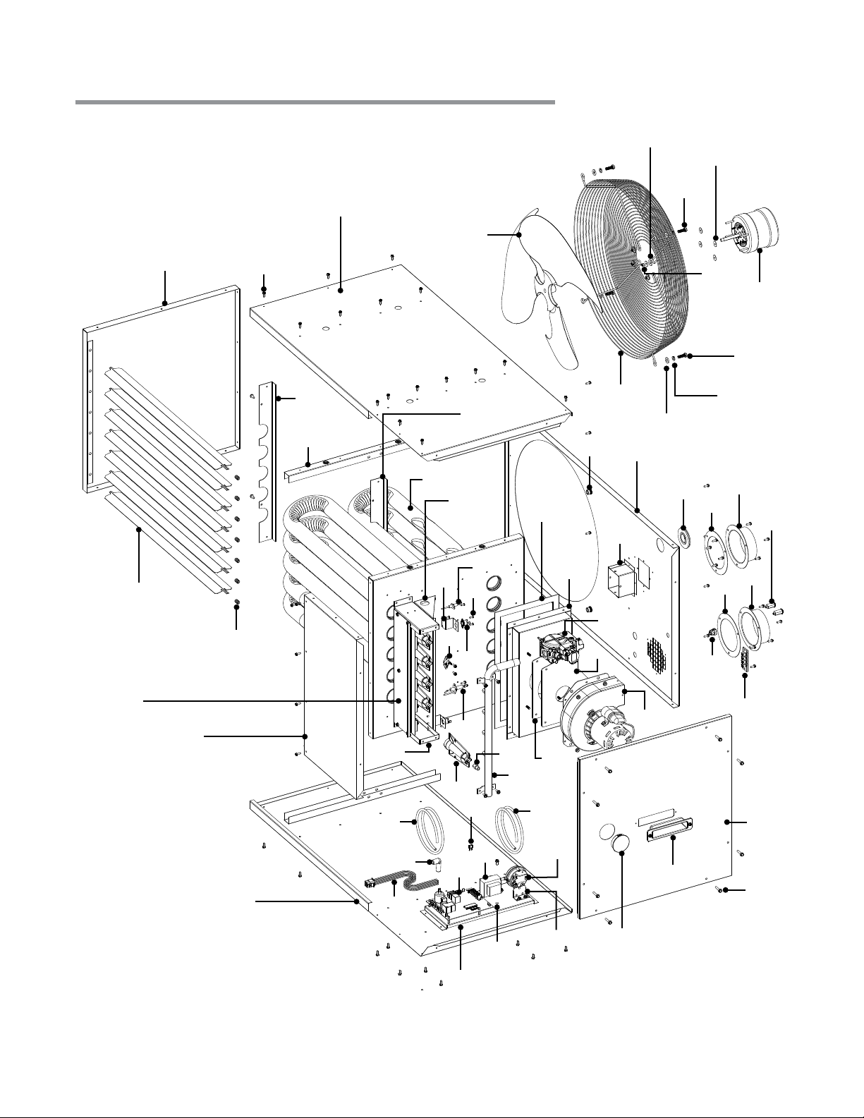
5.0 Maintenance • Heater Components and Parts List
FA Series Cabinet 3 (FA-100 & FA-125) Parts Listing
FA Series
Figure 5.1 • Heater Assembly Components
3105
3102
2113
212
3831,
3833,
121
3112
3841, 3843
3821, 3823
450
421
282
215
202
262
2461,
2462,
3111,
4111,
3101
623
236
233
217
243
235
263
200
200
3150,
4150,
217
234
614
327
614
724,
725,
734,
735,
3103
251
3104
705
551
554
552
425
550
702
553
300
422
303
326
214
441
714, 715
630
203
642,
643,
271
40 0, 410
690
115
603
242
329
3106
114
211
48
Page 49
FA Series
5.0 Maintenance • Heater Components and Parts List
Chart 5.1 • FA Series Cabinet 3 (FA-100 & FA-125) Parts List
Part No. Description Part No. Description
CK P_ 54 _ 4 Propane Conversion Kit (FA-100) UF-552 Spark Igniter Boot
CKP_54_5 Propane Conversion Kit (FA-125) UF-553 Ignition Control Circuit Board
UF-114 Service Access Handle UF-554 Wire Harness
UF-115 Burner Sight Glass UF-603 Inducer Motor Assembly, Large
UF-121 Mounting Rail UF- 614 4" Vent Collar (Qty. 2)
UF-200 4" Vent Collar Gasket (Qty. 2) UF-623 Fan Housing Outlet Collar
UF-202 Exhaust Collection Chamber Gasket UF-630 Pressure Switch Tubing
UF-203 Restrictor Plate Gasket UF-642 Pressure Switch, 1.55" WC
UF-211 #10 x 1" SMS - Point Tip UF-643 Pressure Switch, 1.70” WC
UF-212 #8 x 1/2" SMS - Point Tip UF-690 Restrictor Plate (Indicate Size)
UF-213 #10 x 1/2" SMS - Point Tip UF-702 Inshot Burner, 5/16" Port
UF-214 #10-32 Ground Screw UF-705 Burner Chamber Sides
UF-215 #2 Phillips Pan Head x 1/2" SMS - Blunt Tip UF-714 Manifold Pipe, 4 Burner
UF-217 5/16" - 18 x 1" Bolt UF-715 Manifold Pipe, 5 Burner
UF-233 5/16" Flat Washer UF-724 Burner Mounting Rail, 4 Burner
UF-234 5/16" Lock Washer UF-725 Burner Mounting Rail, 5 Burner
UF-235 #10 Flat Washer UF-73 4 Burner Chamber Body, 4 Burner
UF-236 #10 Rubber Washer UF-735 Burner Chamber Body, 5 Burner
UF-242 Strain Relief Bushing, Cordgrip U F- 2 113 Louver
UF-243 1/2" Gas Pipe Grommet UF-2461 Exhaust Collection Chamber, 4 Burner
UF-251 Louver Spring UF-2462 Exhaust Collection Chamber, 5 Burner
UF-262 5/16"-18 Threaded Nut Insert UF-3101 Back Panel #3
UF-263 #10-32 Nyloc Nut UF-3102 Right Side Panel #3
UF-271 Pressure Switch Bracket UF-3103 Front Panel #3
UF-282 Limit Switch Bracket UF-3104 Bottom Panel #3
UF-300 Component Panel UF-310 5 Top Panel #3
UF-303 3 Amp ATO Fuse UF-310 6 Service Access Door #3
UF-326 40VA Transformer, 120/24 UF- 3111 18" Fan Guard, Rectangle Pattern
UF-327 Indicator Light, 24VAC UF- 3112 18" Axial Fan Blade, 1/2" Hub
UF-329 Terminal Strip UF-3150 Axial Fan Motor, 1/8 HP, 1075 RPM
UF-400 1/2" Gas Valve - Natural Gas UF-3821 Tube and Vest Panel Assembly (4 Tubes)
UF- 410 1/2" Gas Valve - Propane Gas UF-3823 Tube and Vest Panel Assembly (5 Tubes)
UF-421 Flame Sensor UF-3831 Left Tube Support (4 Tubes)
UF-422 Limit Switch, Flame Rollout UF-3833 Left Tube Support (5 Tubes)
UF-425 Limit Switch, Tube Temperature UF-3841 Right Tube Support (4 Tubes)
UF- 4 41 Gas Orifice (Indicate Size) UF-3843 Right Tube Support (5 Tubes)
UF-450 Burner Chamber Support Bracket U F - 4111 18” Fan Guard, Square Pattern
UF-550 Spark Igniter UF- 4150 Axial Fan Motor, 1/6 HP, 1625 RPM
UF-551 Spark Igniter Wire
49
Page 50
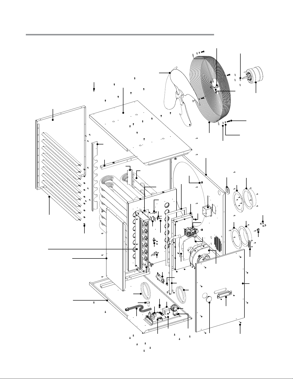
5.0 Maintenance • Heater Components and Parts List
FA Series Cabinet 4 (FA-150, FA-175 & FA-200) Parts Listing
FA Series
Figure 5.2 • Heater Assembly Components
212
4105
4102
4831,
4832,
121
4841,
4842,
4112
4821, 4822
450
421
202
262
4461,
4462,
5111
4101
623
236
233
243
235
263
5150
217
234
615
201
2113
726,
727,
736,
737,
4103
4104
251
551
552
554
705
282
425
550
553
300
422
215
702
303
326
214
203
441
716, 717
630
642
271
213
690
40 0, 410
603
115
114
201
327
615
242
329
4106
211
50
Page 51
FA Series
5.0 Maintenance • Heater Components and Parts List
Chart 5.2 • FA Series Cabinet 4 (FA-150, FA-175 & FA-200) Parts List
Part No. Description Part No. Description
CK P_ 54 _ 6 Propane Conversion Kit (FA-150) UF-551 Spark Igniter Wire
CK P_ 54 _ 7 Propane Conversion Kit (FA-175) UF-552 Spark Igniter Boot
CK P_1. 4 5_7 Propane Conversion Kit (FA-200) UF-553 Ignition Control Circuit Board
UF-114 Service Access Handle UF-554 Wire Harness
UF-115 Burner Sight Glass UF-603 Inducer Motor Assembly, Large
UF-121 Mounting Rail UF-615 6" Vent Collar (Qty. 2)
UF-201 6" Vent Collar Gasket (Qty. 2) UF-623 Fan Housing Outlet Collar
UF-202 Exhaust Collection Chamber Gasket UF-630 Pressure Switch Tubing
UF-203 Restrictor Plate Gasket UF-642 Pressure Switch, 1.55" WC
UF-211 #10 x 1" SMS - Point Tip UF-690 Restrictor Plate (Indicate Size)
UF-212 #8 x 1/2" SMS - Point Tip UF-702 Inshot Burner, 5/16" Port
UF-213 #10 x 1/2" SMS - Point Tip UF-705 Burner Chamber Sides
UF-214 #10-32 Ground Screw UF-716 Manifold Pipe, 6 Burner
UF-215 #2 Phillips Pan Head x 1/2" SMS - Blunt Tip UF-717 Manifold Pipe, 7 Burner
UF-217 5/16" - 18 x 1" Bolt UF-726 Burner Mounting Rail, 6 Burner
UF-233
UF-234 5/16" Lock Washer UF-73 6 Burner Chamber Body, 6 Burner
UF-235 #10 Flat Washer UF-737 Burner Chamber Body, 7 Burner
UF-236 #10 Rubber Washer UF-2113 Louver
UF-242 Strain Relief Bushing, Cordgrip UF- 4101 Back Panel #4
UF-243 1/2" Gas Pipe Grommet UF- 410 2 Right Side Panel #4
UF-251 Louver Spring UF- 4103 Front Panel #4
UF-262 5/16"-18 Threaded Nut Insert UF- 4104 Bottom Panel #4
UF-263 #10-32 Nyloc Nut UF-410 5 Top Panel #4
UF-271 Pressure Switch Bracket UF-410 6 Service Access Door #4
UF-282 Limit Switch Bracket U F -4112 22" Axial Fan Blade, 1/2" Hub
UF-300 Component Panel UF-4461 Exhaust Collection Chamber, 6 Burner
UF-303 3 Amp ATO Fuse UF-4462 Exhaust Collection Chamber, 7 Burner
UF-326 40VA Transformer, 120/24 UF-4821 Tube and Vest Panel Assembly (6 Tubes)
UF-327 Indicator Light, 24VAC UF-4822 Tube and Vest Panel Assembly (7 Tubes)
UF-329 Terminal Strip UF-4831 Left Tube Support (6 Tubes)
UF-400 1/2" Gas Valve - Natural Gas UF-4832 Left Tube Support (7 Tubes)
UF- 410 1/2" Gas Valve - Propane Gas UF- 4 8 41 Right Tube Support (6 Tubes)
UF-421 Flame Sensor UF-4842 Right Tube Support (7 Tubes)
UF-422 Limit Switch, Flame Rollout UF- 5111 22" Fan Guard, Rectangle Pattern
UF-425 Limit Switch, Tube Temperature UF-5150 Axial Fan Motor, 1/3 HP, 1075 RPM
UF- 4 41 Gas Orifice (Indicate Size)
UF-450 Burner Chamber Support Bracket
UF-550 Spark Igniter
5/16" Flat Washer UF-727 Burner Mounting Rail, 7 Burner
51
Page 52
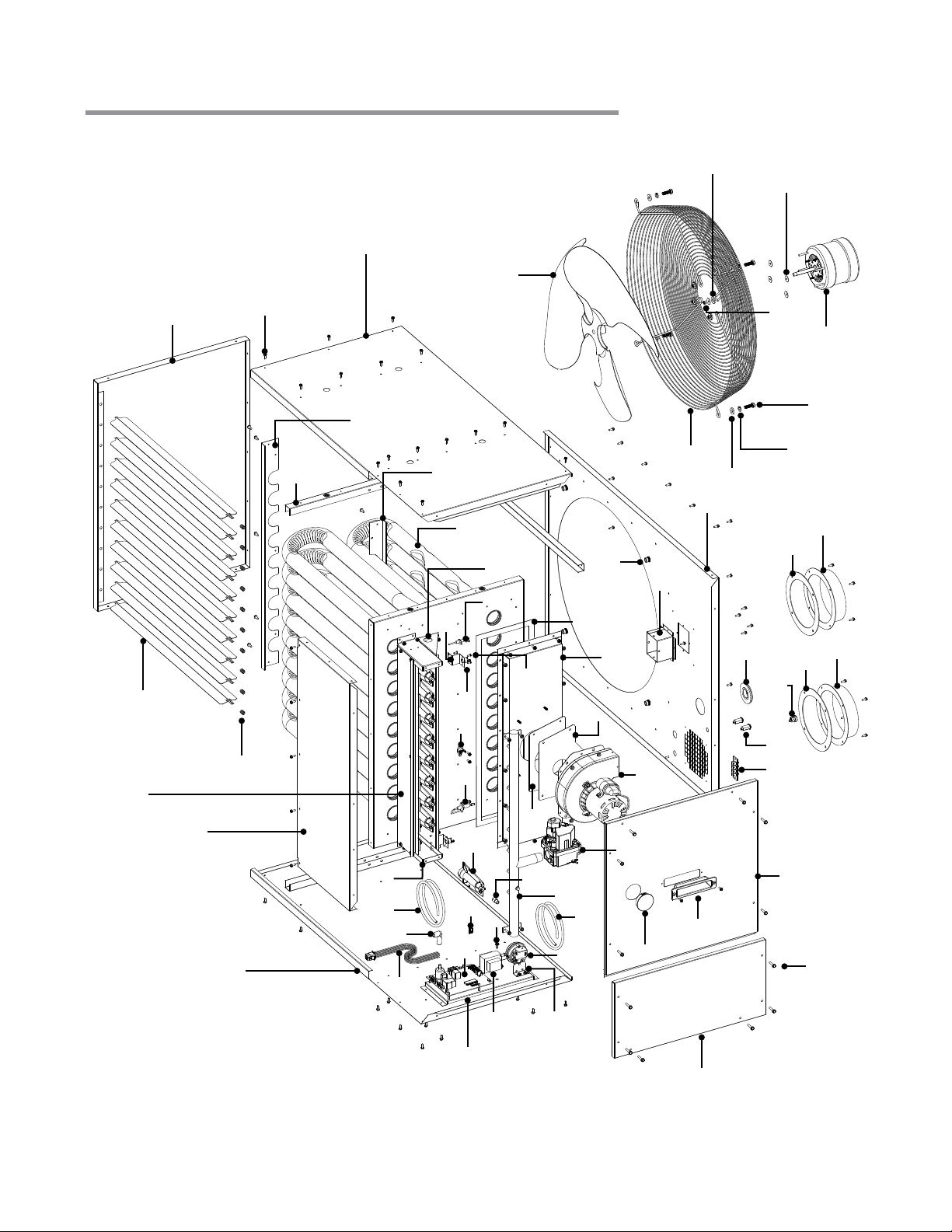
5.0 Maintenance • Heater Components and Parts List
FA Series Cabinet 5 (FA-225 & FA-250) Parts Listing
Figure 5.3 • Heater Assembly Components
5105
4112
FA Series
236
235
2113
729,
739,
5102
5103
5104
251
212
121
5831,
705
551
552
554
5841
282
422
425
5821
550
702
303
553
450
421
214
215
203
441
719
641
262
202
690
630
5461
401, 411
115
623
603
5111
114
233
5101
244
263
242
327
329
234
201
201
5106
5150
217
615
615
211
300
52
326
271
5107
Page 53
FA Series
5.0 Maintenance • Heater Components and Parts List
Chart 5.3 • FA Series Cabinet 5 (FA-225 & FA-250) Parts List
Part No. Description Part No. Description
CK P_ 54 _ 9 Propane Conversion Kit (FA-225) UF-425 Limit Switch, Tube Temperature
CK P_1. 4 5_ 9 Propane Conversion Kit (FA-250) UF-441 Gas Orifice (Indicate Size)
UF-114 Service Access Handle UF-450 Burner Chamber Support Bracket
UF-115 Burner Sight Glass UF-550 Spark Igniter
UF-121 Mounting Rail UF- 551 Spark Igniter Wire
UF-201 6" Vent Collar Gasket (Qty. 2) UF-552 Spark Igniter Boot
UF-202 Exhaust Collection Chamber Gasket UF-553 Ignition Control Circuit Board
UF-203 Restrictor Plate Gasket UF-554 Wire Harness
UF-211 #10 x 1" SMS - Point Tip UF-603 Inducer Motor Assembly, Large
UF-212 #8 x 1/2" SMS - Point Tip UF-615 6" Vent Collar (Qty. 2)
UF-213 #10 x 1/2" SMS - Point Tip UF-623 Fan Housing Outlet Collar
UF-214 #10-32 Ground Screw UF-630 Pressure Switch Tubing
UF-215 #2 Phillips Pan Head x 1/2" SMS - Blunt Tip UF-641 Pressure Switch, 1.30" WC
UF-217 5/16" - 18 x 1" Bolt UF-690 Restrictor Plate (Indicate Size)
UF-233 5/16" Flat Washer UF-702 Inshot Burner, 5/16" Port
UF-234 5/16" Lock Washer UF-705 Burner Chamber Sides
UF-235 #10 Flat Washer UF-719 Manifold Pipe, 9 Burner
UF-236 #10 Rubber Washer
UF-242
UF-244 3/4" Gas Pipe Grommet UF-2113 Louver
UF-251 Louver Spring UF- 4112 22” Axial Fan Blade, 1/2” Hub
UF-262 5/16"-18 Threaded Nut Insert UF-5101 Back Panel #5
UF-263 #10-32 Nyloc Nut UF-5102 Right Side Panel #5
UF-271 Pressure Switch Bracket UF-5103 Front Panel #5
UF-282 Limit Switch Bracket UF-5104 Bottom Panel #5
UF-300 Component Panel UF-510 5 Top Panel #5
UF-303 3 Amp ATO Fuse UF-5106 Service Access Door (Upper) #5
UF-326 40VA Transformer, 120/24 UF-5107 Service Access Door (Lower) #5
UF-327 Indicator Light, 24VAC UF- 5111 22” Fan Guard, Rectangle Pattern
UF-329 Terminal Strip UF-5150 Axial Fan Motor, 1/3 HP, 1075 RPM
UF-401 3/4" Gas Valve - Natural Gas UF-5461 Exhaust Collection Chamber, 9 Burner
UF- 411 3/4" Gas Valve - Propane Gas UF-5821 Tube and Vest Panel Assembly (9 Tubes)
UF-421 Flame Sensor UF-5831 Left Tube Support (9 Tubes)
UF-422 Limit Switch, Flame Rollout UF - 5 8 41 Right Tube Support (9 Tubes)
Strain Relief Bushing, Cordgrip
UF-729 Burner Mounting Rail, 9 Burner
UF-73 9 Burner Chamber Body, 9 Burner
53
Page 54
5.0 Maintenance • Maintenance Log
FA Series
Maintenance Log
Date Maintenance Performed Replacement Parts Required
54
Page 55

FA Series
5.0 Maintenance • Limited Warranty
Limited Warranty Terms and Conditions
One-Year Limited Warranty. The heaters covered in this manual are warranted by Detroit Radiant Products
Company to the original user against defects in workmanship or materials under normal use for one year after
date of purchase. Any part which is determined to be defective in material or workmanship and returned to an
authorized service location, as Detroit Radiant Products Company designates, shipping costs prepaid, will be, as
the exclusive remedy, repaired or replaced at Detroit Radiant Products Company’s option. For limited warranty
claim procedures, see PROMPT DISPOSITION below. This limited warranty gives purchasers specific legal
rights which vary from jurisdiction to jurisdiction.
Additional Limited Warranty. In addition to the above mentioned one-year warranty, Detroit Radiant Products
Company warrants the original purchaser an additional extension on the heat exchangers and burners. This
extension excludes electrical/purchased components.
General Conditions. The Company will not be responsible for labor charges for the analysis of a defective
condition of the heater or for the installation of replacement parts. The warranties provided herein will not apply if
the input of the heater exceeds the rated input at time of manufacturing or if the heater in the judgment of the
Company has been subjected to misuse, excessive dust, improper conversion, negligence, accident, corrosive
atmospheres, excessive thermal shock, excessive vibration, physical damage to the heater, alterations by
unauthorized service personnel, operation contrary to the Company’s instructions or if the serial number has
been altered, defaced, or removed. The Company shall not be liable for any default or delay in the performance
of these warranties caused by contingency beyond its control, including war, government restriction or restraints,
strikes, fire, flood, short or reduced supply of raw materials, or parts.
Limitation of Liability. To the extent allowable under applicable law, Detroit Radiant Products Company’s liability
for consequential and incidental damages is expressly disclaimed. Detroit Radiant Products Company’s liability in
all events is limited to and shall not exceed the purchase price paid.
Warranty Disclaimer. Detroit Radiant Products Company has made a diligent effort to provide product
information and illustrate the products in this literature accurately; however, such information and illustrations are
for the sole purpose of identification, and do not express or imply a warranty that the products are merchantable,
or fit for a particular purpose, or that the products will necessarily conform to the illustrations or descriptions.
Except as provided below, no warranty or affirmation of fact, expressed or implied, other than as stated in the
“LIMITED WARRANTY” above is made or authorized by Detroit Radiant Products Company.
Product Suitability. Many jurisdictions have codes and regulations governing sales, construction, installation,
and/or use of products for certain purposes, which may vary from those in neighboring areas. While Detroit
Radiant Products Company attempts to assure that its products comply with as many codes, it cannot guarantee
compliance, and cannot be responsible for how the product is installed or used. Before purchase and use of a
product, review the product applications, and all applicable national and local codes and regulations, and be sure
that the product, installation, and use will comply with them. Certain aspects of disclaimers are not applicable to
consumer products:
e.g., (a) some jurisdictions do not allow the exclusion or limitation of incidental or consequential damages, so the
above limitation or exclusion may not apply to you: (b) also, some jurisdictions do not allow a limitation on how
long an implied warranty lasts, consequently the above limitation may not apply to you: and (c) by law, during the
period of this limited warranty, any implied warranties of implied merchantability or fitness for a particular purpose
applicable to consumer products purchased by consumers, may not be excluded or otherwise disclaimed.
Prompt Disposition. Detroit Radiant Products Company will make a good faith effort for prompt correction or
other adjustment with respect to any product which proves to be defective within limited warranty. For any product
believed to be defective within limited warranty, first write or call dealer from whom the product was purchased.
Dealer will give additional directions. If unable to resolve satisfactorily, write to Detroit Radiant Products Company
at 21400 Hoover Road, Warren, Michigan 48089, listing dealer’s name, address, date and number of dealer’s
invoice, and describe the nature of the defect. Title and risk of loss pass to buyer on delivery to common carrier. If
product was damaged in transit to you, file claim with carrier.
Registration. Register on-line at www.drp-co.com/warranty.
55
Page 56
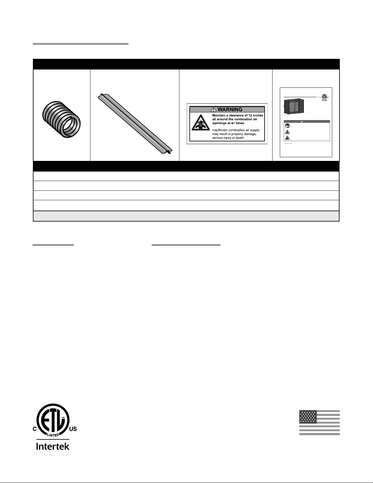
5.0 Maintenance • Kit Contents Check List
Print: 1M-01/13 (DRP)
!
FA Series
Kit Contents Check List
Chart 5.4 • Kit Contents for FA Series
FA Series Kit Contents
UF-251
Springs
UF-2113
Louvers
LLUH008
Room Air
Clearance Label
Part No. Description FA-100 FA-125 FA-150 FA -175 FA-200 FA-22 5 FA-250
UF-251 Spring 7 7 9 9 9 10 10
UF-2113 Louver 7 7 9 9 9 10 10
LLUH008 Room Air Clearance Label 1 1 1 1 1 1 1
LIOFA FA Series Installation Manual 1 1 1 1 1 1 1
FA Series Manual
F/N: LIOFA
Detroit Radiant Products Company
FA Series Manual
Installation, Operation,
Maintenance and Parts
The FA Series heater is a gas-fired unit heater. This manual provides specific information related to the
FA Series models. All persons involved with the installation, operation and maintenance of the heater
system must read and understand the information in this manual.
For Your Safety
If you smell gas:
• Open windows.
• Do not touch any electrical switch.
• Extinguish any open ame.
• Do not use any phone in your building.
WARNI NG
Improper installation, adjustment, alteration, service or maintenance can cause
property damage, serious injury or death. Read and understand the installation,
operating and maintenance instruction thoroughly before installing or servicing this
equipment.
This heater must be installed and serviced by trained gas installation and service
personnel only. Failure to comply could result in personal injury, asphyxiation, death,
and fire or property damage.
Do not store or use gasoline or other flammable vapors and liquids in the vicinity of
this or any appliance.
Do not use this heater in indoor living or sleeping quarters! Installation of this unit in
a residential indoor living space may result in property damage, serious injury,
asphyxiation or death.
• Immediately call your gas supplier from a neighbor’s phone.
• Follow the gas supplier’s instructions.
• If you cannot reach your gas supplier, call the re department.
Keep these instructions for future reference.
LIOFA-Rev. 00413
Filled By:
Approvals
• ANSI Z83.20b and CSA 2.34.
• Indoor approval.
• Commercial approval.
Limited Warranty
• 1 year - components.
• 5 years - heat exchangers.
• 10 years - burners.
• See page 55 for terms and conditions.
© 2014 Detroit Radiant Products Co.
21400 Hoover Road • Warren, MI 48089
Phone: (586) 756-0950 Fax: (586) 756-2626
www.detroitradiant.com • [email protected]
Proudly Made
in the U.S.A.
56
 Loading...