


S83/85 Ultrasonic Generator
A40-064
BRANSON
Precision Processing Group
41 Eagle Road
Danbury, CT 06-813-1961
(203) 796-0400
S83/85 Ultrasonic Generator
A40-064 Rev 0 Page 1

1Introduction
1.1Manual Change Information
At Branson, we strive to maintain our position as the leader in ultrasonic cleaning and related technologies by continually improving circuits and components in our equipment. These improvements are incorporated as soon as they are developed and thoroughly tested.
Information concerning any improvements will be added to the appropriate manual section(s) at the next printing. Therefore, when requesting service assistance for specific units, refer to the revision level of this manual.
S83/85 Ultrasonic Generator |
Manual Change Information |
A40-064 Rev 0 |
Page 3 |

1.2Warranty
1.2.1 Equipment
When used in accordance with written instructions and under normal operating conditions, Branson manufactured products are guaranteed to be free from defects in material and workmanship for ONE YEAR. In addition, Branson Series 8000 Power Supplies are guaranteed for TWO YEARS. Transducer elements and their bond are guaranteed for the LIFETIME of the radiating surface when used in accordance with manufacturer’s instructions. All guarantees are from the date of invoice.
This warranty shall not apply to the following:
•Cavitation erosion of tank or immersible transducer surfaces, which is process related and a normal occurrence in the operation of an ultrasonic cleaning system.
•Equipment subjected to misuse, improper installation, alteration, neglect, or accident.
Any equipment which proves defective during the stated period will be repaired or replaced at the sole discretion of Branson, F.O.B. Danbury, CT, or other repair depot as specified by Branson.
1.2.2Process
Branson will guarantee any process developed in their applications laboratory for ninety days following the installation of recommended Branson equipment when the following stipulations are met:
•The customer must supply a sufficient quantity of parts with soils representative of the parts to be cleaned in production.
•A sample of those parts will be labeled and sealed.
•The balance of the customer-supplied parts will be cleaned using a process developed and recommended by Branson.
•Cleanliness levels will be determined by a methodology agreed upon by Branson and its customer.
•A sample of the cleaned parts will be labeled and sealed as representative of the recommended process.
Branson guarantees, in accordance with the above, that parts received into the Branson precision cleaning system with the same level and condition of soil as the laboratory and subjected to the recommended process will be cleaned to the same level as that demonstrated in the laboratory.
Should the equipment or process fail to meet the agreed upon level of cleanliness, Branson will be afforded a reasonable time to remedy the problem. Following that period, the customer will have the right to return the equipment in accordance with normal return policies.
1.2.3Limitations of Liability
Branson’s liability, whether based on warranty, negligence, or other cause, shall not in any case exceed the cost of the equipment. In no case shall Branson be responsible for any consequential damages arising out of commercial loss.
This warranty is limited to the original purchaser and is not transferable. No warranties expressed or implied have been made other than those stated herein. SELLER DISCLAIMS ANY WARRANTY OF MERCHANTABILITY OR WARRANTY OF FITNESS FOR A PARTICULAR PURPOSE.
S83/85 Ultrasonic Generator |
Warranty |
A40-064 Rev 0 |
Page 4 |

1.3Warnings
Warning: |
Ultrasonic Power supplies produce high voltage. Before working on an |
|
ultrasonic power supply, do the following (1) turn off the ultrasonic |
|
power supply and unplug AC voltage; and (2) remove the cover and |
|
allow at least 1 minute for capacitors to discharge. |
Warning: |
Transducer (elements) can hold a high voltage charge. Before |
|
troubleshooting or making repairs, discharge voltage by momentarily |
|
shorting pins A and B of the RF connector that plugs into the ultrasonic |
|
power supply. |
S83/85 Ultrasonic Generator |
Warnings |
A40-064 Rev 0 |
Page 5 |

1.4Table of Contents
S83/85 Ultrasonic Generator .......................................................................................................................... |
1 |
||
1 |
Introduction ........................................................................................................................................ |
3 |
|
|
1.1 |
Manual Change Information ....................................................................................................... |
3 |
|
1.2 |
Warranty ..................................................................................................................................... |
4 |
|
1.3 |
Warnings..................................................................................................................................... |
5 |
|
1.4 |
Table of Contents........................................................................................................................ |
6 |
|
1.5 |
List of Figures............................................................................................................................. |
8 |
|
1.5 |
About This Manual ................................................................................................................... |
13 |
|
1.6 |
General System Description ..................................................................................................... |
13 |
|
1.6.1 |
Ultrasonic Generator Models ............................................................................................ |
14 |
|
1.6.2 |
Options.............................................................................................................................. |
14 |
2 |
Controls ............................................................................................................................................ |
16 |
|
|
2.1 |
Introduction - Component Identification and Specifications .................................................... |
16 |
|
2.2 |
S8500 Controls ......................................................................................................................... |
16 |
|
2.2.1 |
S8500 Control Switches.................................................................................................... |
17 |
|
2.2.2 |
Adjustment Ports............................................................................................................... |
17 |
|
2.2.3 |
Status Annunciators .......................................................................................................... |
18 |
|
2.3 |
S8300 Controls ......................................................................................................................... |
19 |
|
2.4 |
Back Panel ................................................................................................................................ |
20 |
3 |
Installation ........................................................................................................................................ |
22 |
|
|
3.1 |
Installation Overview................................................................................................................ |
22 |
|
3.2 |
Unpacking the Ultrasonic Power Supply .................................................................................. |
22 |
|
3.3 |
Electrical Requirements ............................................................................................................ |
22 |
|
3.4 |
Locating the Ultrasonic Power Supply ..................................................................................... |
22 |
|
3.5 |
Matching Ultrasonic Equipment ............................................................................................... |
24 |
|
3.6 |
Connecting the Ultrasonic Power Supply ................................................................................. |
25 |
|
3.7 |
Ultrasonic Tank Installation...................................................................................................... |
26 |
|
3.7.1 |
Overview........................................................................................................................... |
26 |
|
3.7.2 |
Installation Do’s and Don’ts ............................................................................................. |
27 |
|
3.7.3 |
Tank Features.................................................................................................................... |
28 |
|
3.7.4 |
Installing an Ultrasonic Tank............................................................................................ |
28 |
4 |
Operation .......................................................................................................................................... |
30 |
|
|
4.1 |
Overview .................................................................................................................................. |
30 |
|
4.2 |
Key Concepts............................................................................................................................ |
30 |
|
4.3 |
U/S Mode Function................................................................................................................... |
30 |
|
4.4 |
Setting the Power Level Function............................................................................................. |
32 |
|
4.5 |
Power Modulation Mode (S85 only) ........................................................................................ |
33 |
|
4.6 |
Sweep Mode Function .............................................................................................................. |
34 |
|
4.6.1 |
S83 Sweep Mode .............................................................................................................. |
34 |
|
4.6.2 |
S85 Sweep Mode .............................................................................................................. |
34 |
|
4.7 |
Rate Function (S85 only) .......................................................................................................... |
35 |
|
4.8 |
Reset Function .......................................................................................................................... |
36 |
5 |
System Installation............................................................................................................................ |
38 |
|
|
5.1 |
Overview .................................................................................................................................. |
38 |
|
5.1.1 |
Do’s – ............................................................................................................................... |
38 |
|
5.1.2 |
Don’ts – ............................................................................................................................ |
39 |
|
5.2 |
Elements – Immersible Transducers ......................................................................................... |
39 |
|
5.3 |
Immersible Transducer Installation, Wiring ............................................................................. |
40 |
|
5.3.1 |
Wiring Procedures ............................................................................................................ |
40 |
|
5.3.2 |
Preparing the RF Cable..................................................................................................... |
41 |
|
5.4 |
Immersible Installation ............................................................................................................. |
42 |
|
5.4.1 |
Immersible Types ............................................................................................................. |
42 |
S83/85 Ultrasonic Generator |
Table of Contents |
A40-064 Rev 0 |
Page 6 |

|
5.5 |
Junction Boxes .......................................................................................................................... |
43 |
|
5.6 |
Mounting Junction Boxes.......................................................................................................... |
44 |
|
5.7 |
Configuration Diagrams ............................................................................................................ |
45 |
|
5.7.1 |
12 Element Generators ...................................................................................................... |
45 |
|
5.7.2 |
18 Element Generators ...................................................................................................... |
46 |
|
5.7.3 |
24 Element generators ....................................................................................................... |
47 |
|
5.7.4 |
36 Element Generators ...................................................................................................... |
48 |
|
5.7.5 |
48 Element Generators ...................................................................................................... |
49 |
|
5.8 |
FC-Type Immersible Transducer Installation............................................................................ |
50 |
|
5.8.1 |
FC Immersible Models and Dimensions ........................................................................... |
50 |
|
5.8.2 |
Mounting an FC-Type Immersible Transducer ................................................................. |
51 |
|
5.8.3 |
Mounting FC Junction Boxes ............................................................................................ |
52 |
|
5.8.4 |
Wiring One FC Immersible Transducer (12-elements shown) .......................................... |
53 |
|
5.8.5 |
Wiring Two FC Immersible Transducers (24 elements shown) ........................................ |
54 |
|
5.8.6 |
Wiring Three FC Immersible Transducers (36 elements shown) ...................................... |
55 |
|
5.8.7 |
Wiring Four FC Immersible Transducers (48 elements shown)....................................... |
56 |
|
5.9 |
CB Type Immersible Mounting and Wiring.............................................................................. |
57 |
|
5.9.1 |
CB Type Immersible Transducer Models and Dimensions ............................................... |
57 |
|
5.9.2 |
Mounting a CB-Type Immersible Transducer................................................................... |
58 |
|
5.9.3 |
Wiring CB Immersible Transducers .................................................................................. |
59 |
|
5.9.4 |
CB-Type Immersible Transducers – 12-Element .............................................................. |
60 |
|
5.9.5 |
CB-Type Transducers – 24-Element ................................................................................. |
61 |
|
5.9.6 |
CB-Type Immersible Transducers – 36-Element .............................................................. |
62 |
|
5.9.7 |
CB-Type Immersible Transducers – 48-Element .............................................................. |
63 |
|
5.10 Mounting and Wiring SB-Type Immersible Transducers ......................................................... |
64 |
|
|
5.10.1 SB Type Immersible Transducer Models and Dimensions ............................................... |
64 |
|
|
5.10.2 Mounting an SB Type Immersible Transducer.................................................................. |
65 |
|
|
5.10.3 Mounting and Wiring SB Type Immersible Transducers.................................................. |
66 |
|
|
5.11 Mounting and Wiring EB-Type Immersible Transducers ......................................................... |
67 |
|
|
5.11.1 EB Immersible Transducer Models and Dimensions ........................................................ |
67 |
|
|
5.11.2 Mounting an EB-Type Immersible Transducer ................................................................. |
68 |
|
|
5.11.3 EB Type Immersible Transducer Junction Box Wiring .................................................... |
69 |
|
|
5.11.4 Wiring One EB/SB-Type Immersible Transducer............................................................. |
70 |
|
|
5.11.5 Wiring Two Immersible Transducers in Parallel............................................................... |
71 |
|
6 |
Troubleshooting................................................................................................................................. |
75 |
|
|
6.1 |
Periodic Maintenance ................................................................................................................ |
75 |
|
6.1.1 |
Ultrasonic Power Supplies................................................................................................. |
75 |
|
6.1.2 |
Tanks and Immersible Transducers ................................................................................... |
75 |
|
6.2 |
Trouble-shooting Charts ............................................................................................................ |
76 |
|
6.3 |
Trouble-shooting the Load ........................................................................................................ |
77 |
|
6.4 |
Resistance Charts ...................................................................................................................... |
78 |
|
6.4.1 |
Overview ........................................................................................................................... |
78 |
|
6.4.2 |
Using Resistance Charts .................................................................................................... |
78 |
|
6.5 |
Assemblies................................................................................................................................. |
80 |
|
6.6 |
Parts List.................................................................................................................................... |
80 |
7 |
Options .............................................................................................................................................. |
83 |
|
|
7.1 |
Full Feature Input/Output Board ............................................................................................... |
83 |
|
7.1.1 |
Removing the Cover.......................................................................................................... |
83 |
|
7.1.2 |
Installing the I/O Board ..................................................................................................... |
84 |
|
7.1.3 |
I/O Board Input Signals ..................................................................................................... |
85 |
|
7.1.4 |
I/O Board Output Functions .............................................................................................. |
86 |
|
7.2 |
OEM-I/O Board – STD-392-317............................................................................................... |
89 |
|
7.2.1 |
General .............................................................................................................................. |
89 |
|
7.2.2 |
Kit Components................................................................................................................. |
89 |
|
7.2.3 |
Installation ......................................................................................................................... |
89 |
S83/85 Ultrasonic Generator |
Table of Contents |
A40-064 Rev 0 |
Page 7 |

|
7.2.4 |
OEM I/O Operation .......................................................................................................... |
90 |
|
7.3 |
OEM-I/O Board – 101-063-503 ............................................................................................... |
92 |
|
7.3.1 |
General.............................................................................................................................. |
92 |
|
7.3.2 |
Kit Components ................................................................................................................ |
92 |
|
7.3.3 |
Installation ........................................................................................................................ |
92 |
|
7.3.4 |
OEM I/O Operation .......................................................................................................... |
93 |
|
7.3.5 |
Specifications.................................................................................................................... |
93 |
|
7.4 |
Timer Option ............................................................................................................................ |
96 |
|
7.5 |
Rack Mount Kit ........................................................................................................................ |
97 |
8 |
Assistance ....................................................................................................................................... |
101 |
|
|
8.1 |
Calling the Local Branson Representative.............................................................................. |
101 |
|
8.2 |
Obtaining Replacement Parts.................................................................................................. |
102 |
|
8.3 |
Returning Equipment.............................................................................................................. |
103 |
1.5 |
List of Figures |
|
Figure 1-1 S8500 Ultrasonic Generator........................................................................................................ |
13 |
|
Figure 2-1 S8500 Front Panel....................................................................................................................... |
16 |
|
Figure 2-2 S8500 Control Switches.............................................................................................................. |
17 |
|
Figure 2-3 S8500 Adjustment Ports.............................................................................................................. |
17 |
|
Figure 2-4 Status Annunciators .................................................................................................................... |
18 |
|
Figure 2-5 S8300 Front Panel....................................................................................................................... |
19 |
|
Figure 2-6 S8500 Back Panel ....................................................................................................................... |
20 |
|
Figure 3-1 Ultrasonic Power supply Dimensions ......................................................................................... |
23 |
|
Figure 3-2 Comparing Model Numbers........................................................................................................ |
24 |
|
Figure 3-3 Translating Model Numbers ....................................................................................................... |
24 |
|
Figure 3-4 Alignment of RF Plug ................................................................................................................. |
25 |
|
Figure 3-5 Ultrasonic Tank Features ............................................................................................................ |
28 |
|
Figure 4-1 Operating US Switch S85 ........................................................................................................... |
31 |
|
Figure 4-2 Operating US Switch S83 ........................................................................................................... |
31 |
|
Figure 4-3 S85 Power Level Adjustment ..................................................................................................... |
32 |
|
Figure 4-4 Power Adjustment....................................................................................................................... |
32 |
|
Figure 4-5 S85 Setting Power Modulation Mode ......................................................................................... |
33 |
|
Figure 4-6 Sweep Bandwidth ....................................................................................................................... |
34 |
|
Figure 4-7 Sweep Adjustments..................................................................................................................... |
34 |
|
Figure 4-8 Sweep Width Adjustment ........................................................................................................... |
35 |
|
Figure 4-9 Rate Switch Operation ................................................................................................................ |
35 |
|
Figure 4-10 RESET Switch .......................................................................................................................... |
36 |
|
Figure 5-1 Transducer Elements................................................................................................................... |
39 |
|
Figure 5-2 Junction Box Terminal Connections ........................................................................................... |
40 |
|
Figure 5-3 Task 1.......................................................................................................................................... |
41 |
|
Figure 5-4 Task 2.......................................................................................................................................... |
41 |
|
Figure 5-5 Task 3.......................................................................................................................................... |
41 |
|
Figure 5-6 Task 4.......................................................................................................................................... |
42 |
|
Figure 5-7 Mounting Configurations ............................................................................................................ |
42 |
|
Figure 5-8 Junction Boxes ............................................................................................................................ |
43 |
|
Figure 5-9 Immersible Transducer Configurations 12 Elements .................................................................. |
45 |
|
Figure 5-10 Immersible Transducer Configurations 18 Elements ................................................................ |
46 |
|
Figure 5-11 Immersible Transducer Configurations 24 Elements ................................................................ |
47 |
|
Figure 5-12 Immersible Transducer Configurations 36 Elements ................................................................ |
48 |
|
Figure 5-13 Immersible Transducer Configurations 48 Elements ................................................................ |
49 |
|
Figure 5-14 FC610/FC618 Mounting Dimensions ....................................................................................... |
50 |
|
Figure 5-15 Mounting FC Type Immersibles ............................................................................................... |
51 |
|
Figure 5-16 FC Type Immersible Transducer Junction Box Mounting........................................................ |
52 |
|
S83/85 Ultrasonic Generator |
Table of Contents |
A40-064 Rev 0 |
Page 8 |

Figure 5-17 Wiring One FC Type Immersible Transducer ........................................................................... |
53 |
Figure 5-18 Wiring Two FC Type Immersible Transducers ......................................................................... |
54 |
Figure 5-19 Wiring Three FC Type Immersible Transducers ....................................................................... |
55 |
Figure 5-20 Wiring Four FC Type Immersible Transducers ......................................................................... |
56 |
Figure 5-21 CB Type Immersible Transducer Dimensions........................................................................... |
57 |
Figure 5-22 Mounting CB Type Immersible Transducers............................................................................. |
58 |
Figure 5-23 Mounting and Wiring CB Type Immersible Transducers.......................................................... |
59 |
Figure 5-24 Wiring 1 CB Type Immersible Transducer ............................................................................... |
60 |
Figure 5-25 Wiring 2 CB Type Immersible Transducers .............................................................................. |
61 |
Figure 5-26 Wiring 3 CB Type Immersible Transducers .............................................................................. |
62 |
Figure 5-27 Wiring 4 CB Type Immersible Transducers .............................................................................. |
63 |
Figure 5-28 SB Type Immersible Dimensions .............................................................................................. |
64 |
Figure 5-29 Mounting an SB Type Immersible Transducer.......................................................................... |
65 |
Figure 5-30 Wiring SB Junction Boxes......................................................................................................... |
66 |
Figure 5-31 EB Type Immersible Transducer Dimensions ........................................................................... |
67 |
Figure 5-32 Mounting an EB Type Immersible Transducer.......................................................................... |
68 |
Figure 5-33 EB Immersible Transducer Junction Box Wiring...................................................................... |
69 |
Figure 5-34 Wiring 1 EB/SB Type Immersible Transducer.......................................................................... |
70 |
Figure 5-35 Wiring 2 or More EB/SB Type Immersible Transducers .......................................................... |
71 |
Figure 6-1 Driver Board Test Points ............................................................................................................. |
79 |
Figure 6-2 Ultrasonic Power Supply Top View ............................................................................................ |
80 |
Figure 6-3 Interconnection Diagram ............................................................................................................. |
81 |
Figure 7-1 Removing The Cover................................................................................................................... |
83 |
Figure 7-2 Installing Standoffs...................................................................................................................... |
84 |
Figure 7-3 Installing I/O Board ..................................................................................................................... |
84 |
Figure 7-4 Connector J2 ................................................................................................................................ |
85 |
Figure 7-5 Discrete Input - Sinking Input Type – 6 Points ........................................................................... |
87 |
Figure 7-6 Discrete Outputs – Normally Open Contacts – 2 Points.............................................................. |
87 |
Figure 7-7 Analog Input - 1 Point ................................................................................................................. |
88 |
Figure 7-8 Analog Output - 2 Points ............................................................................................................. |
88 |
Figure 7-9 OEM-I/O Board Installation ........................................................................................................ |
91 |
Figure 7-10 OEM I/O Configuration............................................................................................................. |
93 |
Figure 7-11 External Wiring Diagrams ......................................................................................................... |
94 |
Figure 7-12 OEM I/O Installation ................................................................................................................. |
95 |
Figure 7-13 Timer Option ............................................................................................................................. |
96 |
Figure 7-14 Rack Mount Kit ......................................................................................................................... |
97 |
S83/85 Ultrasonic Generator |
Table of Contents |
A40-064 Rev 0 |
Page 9 |
S83/85 Ultrasonic Generator
A40-064
S83/85 Ultrasonic Generator |
Introduction |
A40-064 Rev 0 |
Page 11 |
1.5About This Manual
This manual contains instructions for installing, operating and maintaining S83/85 Ultrasonic Generators.
At the back of the manual you will find Appendices containing documentation including wiring schematics, plumbing schematics and assembly drawings.
The following definitions apply in this manual:
Note: Inconvenience only if disregarded - no damage or personal injury.
Caution: |
Equipment damage may occur, but not personal injury. |
Warning: |
Personal injury may occur - DO NOT DISREGARD. |
PN indicates Part Number.
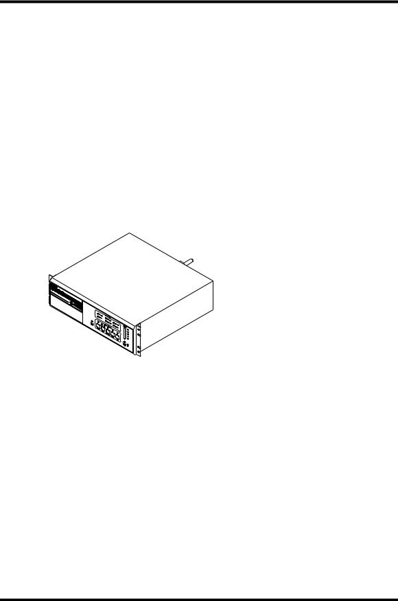
Part(s) indicates your workpiece or component to be cleaned.
Figure 1-1 S8500 Ultrasonic Generator
1.6General System Description
Series 83/85 Ultrasonic Power Supplies deliver ultrasonic electrical energy at 25 kHz, 40 kHz, 80 kHz, 120 kHz or 170 kHz (depending on the model) to an ultrasonic cleaning system. A typical system consists of an ultrasonic power supply and a cleaning tank or immersible. Optional full feature or OEM interface boards allow the generator to be configured and operated remotely.
Note: Series 83/85 ultrasonic power supplies only work with Branson ultrasonic equipment (tanks and immersible transducers.
S83/85 Ultrasonic Generator |
Introduction |
A40-064 Rev 0 |
Page 13 |

1.6.1Ultrasonic Generator Models
Table 1 Ultrasonic Generator Models
|
|
|
|
Nominal |
Number of |
Standard Groupings |
Part Number |
Series |
Model |
Voltage |
Power level |
elements |
|
101-132-468 |
8300 |
S8325-12 |
120 VOLT |
500W |
12 |
1x12 or 2x6 |
|
|
|
||||
101-132-469 |
|
S8325-12 |
230 VOLT |
500W |
12 |
1x12 or 2x6 |
|
|
|
|
|||
101-132-471 |
|
S8325-18 |
" |
750W |
18 |
1x12 & 1x6 or 3x6 |
|
|
|
|
|||
101-132-472 |
|
S8325-24 |
" |
1000W |
24 |
2x12 or 4x6 |
|
|
|
|
|||
101-132-473 |
|
S8325-36 |
" |
1500W |
36 |
3x12 or 6x6 |
|
|
|
|
|||
101-132-474 |
|
S8325-48 |
" |
2000W |
48 |
4x12 or 8x6 |
|
|
|
|
|||
101-132-475 |
|
S8340-12 |
120 VOLT |
500W |
12 |
1x12 or 2x6 |
101-132-476 |
|
S8340-12 |
230 VOLT |
500W |
12 |
1x12 or 2x6 |
|
|
|
|
|||
101-132-478 |
|
S8340-18 |
" |
750W |
18 |
1x12 & 1x6 or 3x6 |
101-132-479 |
|
S8340-24 |
" |
1000W |
24 |
2x12 or 4x6 |
|
|
|
|
|||
101-132-480 |
|
S8340-36 |
" |
1500W |
36 |
3x12 or 6x6 |
|
|
|
|
|||
101-132-481 |
|
S8340-48 |
" |
2000W |
48 |
4x12 or 8x6 |
|
|
|
|
|||
|
|
|
|
|
|
|
101-132-482 |
8500 |
S8525-12 |
120 VOLT |
500W |
12 |
1x12 or 2x6 |
|
|
|
||||
101-132-483 |
|
S8525-12 |
230 VOLT |
500W |
12 |
1x12 or 2x6 |
|
|
|
|
|||
101-132-485 |
|
S8525-18 |
" |
750W |
18 |
1x12 & 1x6 or 3x6 |
|
|
|
|
|||
101-132-486 |
|
S8525-24 |
" |
1000W |
24 |
2x12 or 4x6 |
|
|
|
|
|||
101-132-487 |
|
S8525-36 |
" |
1500W |
36 |
3x12 or 6x6 |
|
|
|
|
|||
101-132-488 |
|
S8525-48 |
" |
2000W |
48 |
4x12 or 8x6 |
|
|
|
|
|||
101-132-489 |
|
S8540-12 |
120 VOLT |
500W |
12 |
1x12 or 2x6 |
|
|
|
|
|||
101-132-490 |
|
S8540-12 |
230 VOLT |
500W |
12 |
1x12 or 2x6 |
|
|
|
|
|||
101-132-492 |
|
S8540-18 |
" |
750W |
18 |
1x12 & 1x6 or 3x6 |
|
|
|
|
|||
101-132-493 |
|
S8540-24 |
" |
1000W |
24 |
2x12 or 4x6 |
|
|
|
|
|||
101-132-494 |
|
S8540-36 |
" |
1500W |
36 |
3x12 or 6x6 |
|
|
|
|
|||
101-132-495 |
|
S8540-48 |
" |
2000W |
48 |
4x12 or 8x6 |
|
|
|
|
|||
|
|
|
|
|
|
|
101-132-682 |
80kHz |
S8580-12 |
230V |
500W |
12 |
1x12 or 2x6 |
|
|
|
||||
101-132-683 |
" |
S8580-18 |
" |
750W |
18 |
1x12 & 1x6 or 3x6 |
|
|
|
||||
101-132-684 |
" |
S8580-24 |
" |
1000W |
24 |
2x12 or 4x6 |
|
|
|
||||
101-132-685 |
120kHz |
S85120-12 |
" |
500W |
12 |
1x12 or 2x6 |
|
|
|
||||
101-132-686 |
" |
S85120-18 |
" |
750W |
18 |
1x12 & 1x6 or 3x6 |
|
|
|
||||
101-132-687 |
170kHz |
S85170-6 |
" |
250W |
6 |
1x6 |
|
|
|
||||
101-132-688 |
" |
S85170-12 |
" |
500W |
12 |
1x12 or 2x6 |
1.6.2Options
Table 2 Generator Options
Part Number |
Type |
Description |
101-063-347 |
|
Rack mount kit |
101-063-503 |
I/O KIT |
OEM ON/OFF with status indication |
101-063-561 |
I/O KIT |
FULL FEATURE, S8500 only |
STD-392-317 |
I/O KIT |
OEM ON/OFF with external interlock |
STD-410-901 |
TIMER |
0-60 Mechanical Timer |
S83/85 Ultrasonic Generator |
Introduction |
A40-064 Rev 0 |
Page 14 |

S83/85 Ultrasonic Generator
A40-064
S83/85 Ultrasonic Generator |
Controls |
A40-064 Rev 0 |
Page 15 |
2Controls
2.1Introduction - Component Identification and Specifications
Operating the ultrasonic power supply requires that you become familiar with the power supply controls, annunciators, and adjustment function.
The front panel contains the following:
•Control switches;
•Status annunciators;
•Adjustment ports.
2.2S8500 Controls
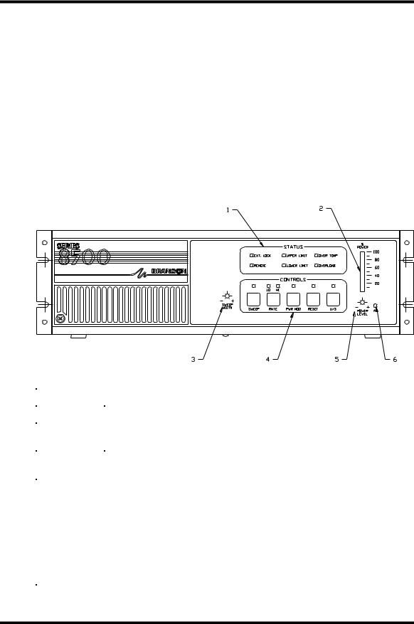
Figure 2-1 S8500 Front Panel
Item No. |
Description |
Function |
|
|
|
1 |
Status annunciators |
Light when fault conditions occur. |
|
|
|
2 |
Ultrasonic (U/S) Power Bargraph |
Displays the percentage of ultrasonic |
|
|
power input. |
|
|
|
3 |
Sweep Width Adjustment port |
Allows adjustment bandwidth of the |
|
|
Sweep mode. |
|
|
|
4 |
Ultrasonic power supply control |
Contains switches to control ultrasonic |
|
switches |
power supply functions and status |
|
|
annunciators. |
|
|
|
5 |
Power Level Adjustment port |
Allows manually setting the ultrasonic |
|
|
power level. |
|
|
|
6 |
AC Power |
Lights when the On/Off switch is on and |
|
|
the ultrasonic power supply has main AC |
|
|
power. |
|
|
|
S83/85 Ultrasonic Generator |
Controls |
A40-064 Rev 0 |
Page 16 |
2.2.1S8500 Control Switches
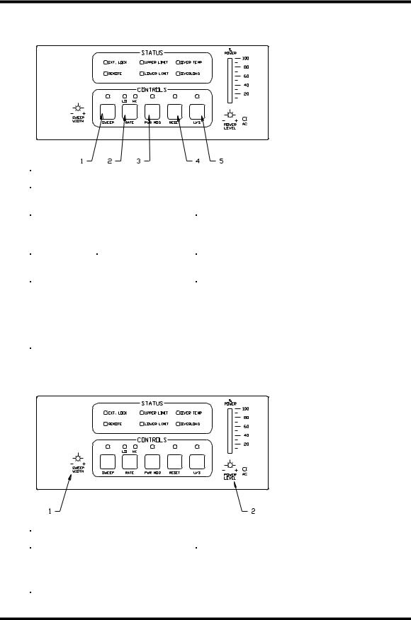
Figure 2-2 S8500 Control Switches
Item No. |
Switch |
Function |
|
|
|
1 |
SWEEP |
Activates Sweep mode; LED is on when |
|
|
sweep is on. |
|
|
|
2 |
RATE |
Toggles between high (“HI” LED on) and |
|
|
low (“LO” LED on) Sweep Rates. Power |
|
|
On default is HIGH rate. |
|
|
|
3 |
POW MOD |
Activates the Power modulation mode; LED |
|
|
is on when Power Modulation is on. |
|
|
|
4 |
RESET |
Press when the LED is on to reset the |
|
|
ultrasonic power supply and turn the LED |
|
|
off. |
|
|
|
5 |
U/S |
Activates ultrasonic output power; LED is |
|
|
on when ultrasonics are on |
|
|
|
2.2.2Adjustment Ports
Figure 2-3 S8500 Adjustment Ports
Item No. |
Adjustment Port |
Function |
|
|
|
1 |
Sweep Width |
Adjusts the Sweep mode bandwidth. |
|
|
|
2 |
Power Level |
Adjusts the percentage of ultrasonic output |
|
|
power (20-100%). |
|
|
|
S83/85 Ultrasonic Generator |
Controls |
A40-064 Rev 0 |
Page 17 |
2.2.3Status Annunciators
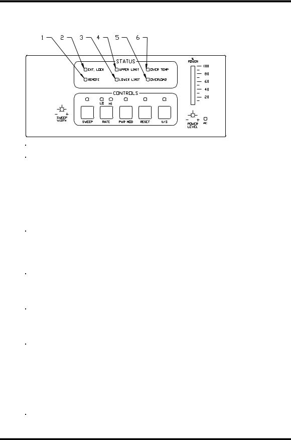
Figure 2-4 Status Annunciators
Item No. |
Annunciator |
Function |
|
|
|
1 |
REMOTE (with I/O option only) |
Annunciator lights when the back panel |
|
|
REMOTE/LOCAL switch is in “REMOTE” |
|
|
position. Note: When operating the |
|
|
ultrasonic power supply in REMOTE |
|
|
position, you cannot activate the following |
|
|
front panel control switches: |
|
|
• SWEEP |
|
|
• RATE |
|
|
• POW MOD |
2 |
EXT. LOCK |
Annunciator lights: (a) when the RF cable is |
|
|
not connected to the ultrasonic power |
|
|
supply, or (b) when it receives a fault |
|
|
condition externally via the I/O port. Power |
|
|
supply is in standby mode when light is on. |
|
|
|
3 |
LOWER LIMIT |
Annunciator lights when the power level |
|
|
drops 20% below the preset power level. |
|
|
Power supply is in standby mode when light |
|
|
is on. |
|
|
|
4 |
UPPER LIMIT |
Annunciator lights when the power level |
|
|
exceeds the preset power level by 20%. |
|
|
Power supply is in standby mode when light |
|
|
is on. |
|
|
|
5 |
OVER LOAD |
Annunciator lights when the ultrasonic |
|
|
power supply overloads due to no-load, or |
|
|
overload condition. Power supply is in |
|
|
Standby mode when light is on. |
|
|
|
6 |
OVER TEMP |
Annunciator lights when the ultrasonic |
|
|
power supply detects an excessive internal |
|
|
temperature. Power supply is in standby |
|
|
mode when light is on. |
|
|
|
S83/85 Ultrasonic Generator |
Controls |
A40-064 Rev 0 |
Page 18 |

2.3S8300 Controls
Figure 2-5 S8300 Front Panel
Item No. |
Control |
Function |
|
|
|
|
|
1 |
OVER TEMP |
Annunciator lights when the ultrasonic |
|
power supply detects an excessive internal |
|||
|
|
||
|
|
temperature. Power supply is in standby |
|
|
|
mode when light is on. |
|
2 |
SYS FAULT |
Annunciator lights when the ultrasonic |
|
|
|
power supply detects an overload, out of |
|
|
|
range power level or an external fault |
|
|
|
condition via the I/O port. Power supply is |
|
|
|
in standby mode when light is on. |
|
|
|
|
|
3 |
AC |
Lights when the On/Off switch is on and the |
|
|
|
ultrasonic power supply has main AC |
|
|
|
power. |
|
|
|
|
|
4 |
US |
Activates ultrasonic output power; LED is |
|
|
|
on when ultrasonics are on |
|
|
|
|
|
5 |
RESET |
Press when the LED is on to reset the |
|
|
|
ultrasonic power supply and turn the LED |
|
|
|
off. |
|
|
|
|
S83/85 Ultrasonic Generator |
Controls |
A40-064 Rev 0 |
Page 19 |
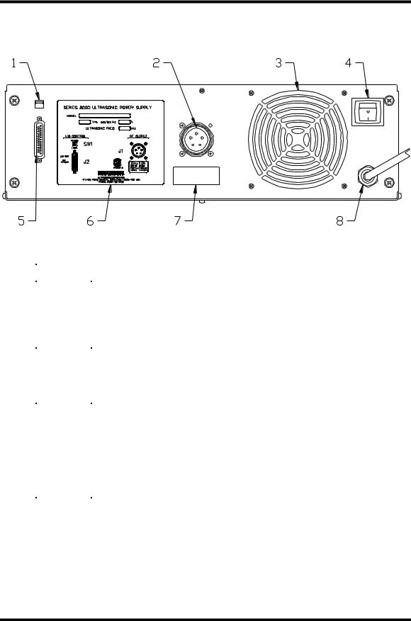
2.4Back Panel
Figure 2-6 S8500 Back Panel
Item No. |
Description |
Function |
|
|
|
1 |
Local/Remote switch SW1 |
Allows switching between local and remote |
|
|
operation. |
|
|
|
2 |
RF Connector |
For connecting the RF cable to the |
|
|
ultrasonic power supply from a tank or |
|
|
immersible transducers. |
|
|
|
3 |
Fan |
Cools the ultrasonic power supply by |
|
|
exhausting hot air. |
|
|
|
4 |
Main On/Off Switch |
Switches on AC power to the ultrasonic |
|
|
power supply. |
|
|
|
5 |
I/O 25-pin D-shell connector (I/O |
Provides connection of cable from |
|
option only). |
ultrasonic power supply to external |
|
|
controller. |
|
|
|
6 |
Product Label |
Displays product information, such as |
|
|
power level, frequency, and serial no. |
|
|
|
7 |
Serial number tag |
Displays serial number of the ultrasonic |
|
|
power supply. |
|
|
|
8 |
Line Cord |
Connects ultrasonic power supply to AC |
|
|
power. |
|
|
|
S83/85 Ultrasonic Generator |
Controls |
A40-064 Rev 0 |
Page 20 |
S83/85 Ultrasonic Generator
A40-064
S83/85 Ultrasonic Generator |
Installation |
A40-064 Rev 0 |
Page 21 |

3Installation
3.1Installation Overview
This section contains a sequence of tasks you must follow to ensure proper installation of your ultrasonic power supply and ultrasonic tank. These tasks include:
1.Unpacking the ultrasonic power supply.
2.Choosing a suitable location for the ultrasonic power supply.
3.Matching ultrasonic equipment (ultrasonic power supply to tanks and immersible transducers).
4.Connecting the ultrasonic power supply.
5.Installing an ultrasonic tank.
3.2Unpacking the Ultrasonic Power Supply
Unpack the ultrasonic power supply as follows:
Step |
Action |
1 |
Unpack the ultrasonic power supply as soon as it arrives, using |
|
normal precautions to prevent damage. |
2 |
Inspect the controls, indicators, and surface for damage. |
3 |
Make sure that all switches are off. |
Note: If damage occurred, notify the shipping company immediately. Retain packing materials for inspection.
3.3Electrical Requirements
Standard line voltage: |
187-253 |
VAC 50/60 |
Hz |
|
108-132 |
VAC 50/60 |
Hz (120 Volt models) |
Table 3 Current Draws (Amps)
Elements |
208V |
230V |
120V |
12 |
2.2 |
2 |
4 |
18 |
3.3 |
3 |
|
24 |
4.4 |
4 |
|
36 |
6.6 |
6 |
|
48 |
8.8 |
8 |
|
3.4Locating the Ultrasonic Power Supply
Locate the ultrasonic power supply according to the following guidelines:
•Make sure the ambient air temperature where you locate and operate the ultrasonic power supply does not exceed 45˚C (113˚F).
•Make sure air flow to the fan is not obstructed.
•Locate the ultrasonic power supply in a electrically non-conductive atmosphere.
•Make sure to locate the ultrasonic power supply in an area free from water spray, splashing, and dripping.
•Ground the ultrasonic power supply receptacle in accordance with local building codes.
S83/85 Ultrasonic Generator |
Installation |
A40-064 Rev 0 |
Page 22 |

•Allow sufficient clearance to access connectors on back of the ultrasonic power supply (7 in. minimum).
•Place the ultrasonic power supply on a horizontal, flat surface top near the tank or transducer in an area away from any heat sources.
Figure 3-1 Ultrasonic Power supply Dimensions
S83/85 Ultrasonic Generator |
Installation |
A40-064 Rev 0 |
Page 23 |

3.5Matching Ultrasonic Equipment
Compare the model numbers on all equipment connected to the ultrasonic power supply. Figure 3-2 shows the labels that contain the model numbers.
Figure 3-2 Comparing Model Numbers
Figure 3-3 Translating Model Numbers
Ultrasonic Power
Supply
25
40
80
S83 120
S85 170 -12
Series 83 or 85 Power Supply
Operating Frequency (kHz)
Number of Elements
Ultrasonic
Tank
25
40
80
120
C(H) 1012 - 170 -12
C Series tank (H-heated)
Interior size of tank (inches, L to R, F to B) Operating Frequency
Number of Elements
FC |
|
CB |
|
SB |
25 |
|
|
EB 1012 - 40 -12 |
|
|
|
|
|
|
|
|
|
|
|
Immersible |
Type of Immersible Transducer |
|
|
|
|
||||
|
|
|
|
||||||
Size of Immersible Transducer |
|
|
|
|
|
||||
|
|
|
|||||||
Transducer |
Operating Frequency |
|
|
|
|
|
|
||
|
|
|
|
|
|
|
|||
|
Number of Elements |
|
|
|
|
|
|
|
|
|
|
|
|
|
|
|
|
||
|
|
|
|
|
|
|
|
|
|
Note: Use 40 kHz transducer with 80, 120 and 170 kHz generators.
S83/85 Ultrasonic Generator |
Installation |
A40-064 Rev 0 |
Page 24 |
3.6Connecting the Ultrasonic Power Supply
Connect the ultrasonic power supply as follows:
Step |
Action |
1 |
Make sure that the ultrasonic power supply is unplugged from the |
|
AC voltage source. |
2 |
Make sure the Main On/Off switch (located on the back panel) is |
|
off. |
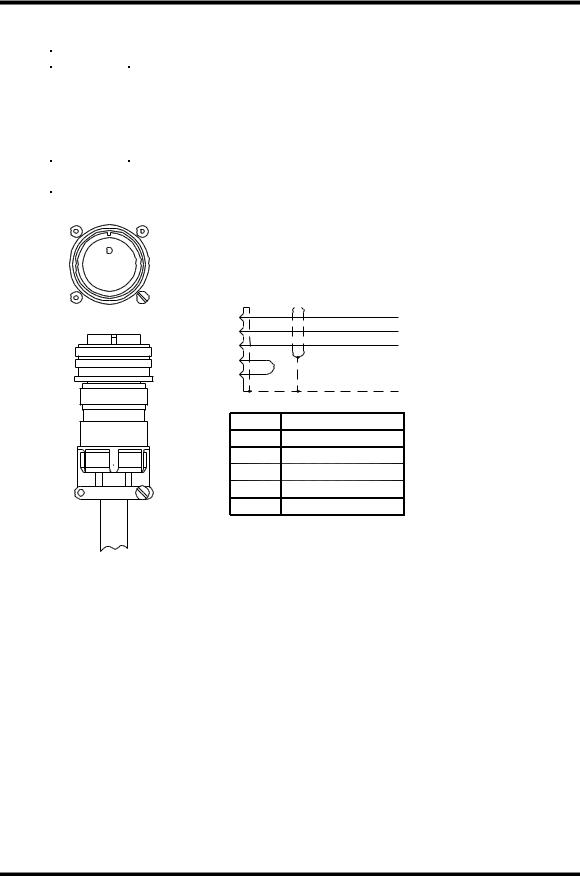
3 |
Align the notch of the RF cable and the slot of RF connector on the |
|
back panel (Figure 3-4 shows the alignment). |
4 |
Plug the RF plug into the RF socket; secure the RF plug by |
|
threading the knurled ring and turning until the end of travel. |
Figure 3-4 Alignment of RF Plug
A
B 
 C
C
D
 E
E
RF Cable
Schematic
A B C D E
Red (+)
Black (-)
Green (Ground)
SHIELD
Pin |
Wire In |
ARed
B |
Black |
|
|
C |
Green |
|
|
D |
Interlock |
EInterlock
Note: If the RF connector is not fully engaged by the knurl ring, the External Lock LED will light.
S83/85 Ultrasonic Generator |
Installation |
A40-064 Rev 0 |
Page 25 |

3.7Ultrasonic Tank Installation
3.7.1Overview
This section contains instructions for installing and operating a Branson ultrasonic tank with the S8000 ultrasonic power supply. The following tables contain model numbers and part numbers for unheated and heated ultrasonic tanks.
Table 4 Ultrasonic Tanks - Unheated
|
Model |
Part No. – |
Part No. – Bright |
|
|
Chromated |
Annealed Finish |
|
|
|
|
|
C1012-25-12 |
101-908-202 |
101-908-228 |
|
|
|
|
|
C1216-25-18 |
101-908-206 |
101-908-227 |
|
|
|
|
|
C1620-25-24 |
101-908-210 |
101-908-223 |
|
|
|
|
|
C2024-25-36 |
101-908-214 |
101-908-219 |
|
|
|
|
|
C1012-40-12*@& |
101-908-200 |
101-908-229 |
|
|
|
|
|
C1216-40-18*@ |
101-908-204 |
101-908-226 |
|
|
|
|
|
C1620-40-24* |
101-908-208 |
101-908-221 |
|
|
|
|
|
C2024-40-36 |
101-908-212 |
101-908-218 |
|
|
|
|
Table 5 Ultrasonic Tanks - Heated |
|
||
|
|
|
|
|
Model |
Part No. – |
Part No. – Bright |
|
|
Chromated |
Annealed Finish |
|
|
|
|
|
CH1012-25-12 |
101-908-203 |
101-908-230 |
|
|
|
|
|
CH1216-25-18 |
101-908-207 |
101-908-225 |
|
|
|
|
|
CH1620-25-24 |
101-908-211 |
101-908-222 |
|
|
|
|
|
CH2024-25-36 |
101-908-215 |
101-908-216 |
|
|
|
|
|
CH1012-40-12*@& |
101-908-201 |
101-908-231 |
|
|
|
|
|
CH1216-40-18*@ |
101-908-205 |
101-908-224 |
|
|
|
|
|
CH1620-40-24* |
101-908-209 |
101-908-220 |
|
|
|
|
|
CH2024-40-36 |
101-908-213 |
101-908-217 |
|
|
|
|
* May be operated with 80 kHz generator @ May be operated with 120 kHz generator
&May be operated with 170 kHz generator
S83/85 Ultrasonic Generator |
Installation |
A40-064 Rev 0 |
Page 26 |

3.7.2Installation Do’s and Don’ts
1.DO make sure you have all necessary system components: the RF cable, the interconnecting jumper cables, and the junction boxes.
2.DO ensure that the frequency and number of elements (transducers) of the ultrasonic power supply matches that of the ultrasonic tank load.
3.DO compare the numbers on the RF cable label and the ID plate on the back panel of the ultrasonic power supply to make sure they match.
4.DO turn off main power switches.
5.DO make sure to ground the ultrasonic power supply in accordance with local building and safety codes.
6.DO check the line voltage on the ID plate for the ultrasonic power supply line voltage to ensure it matches your AC source voltage
7.DO use Power Modulation mode – after initially filling the ultrasonic tank – to remove large obstructive gas bubbles which shield the ultrasonic energy. Run for 10-15 minutes at operating temperature.
8.DO maintain the liquid level of the ultrasonic tank with 3 inches of the top – the same level as the fill port.
9.DO, in application with large parts which displace significant amount of liquid, take care not to expose the heaters.
10.DO make sure to operate an ultrasonic tank from the same ultrasonic power supply.
11.DO ensure parts are at least 2 inches from the radiating surface of the ultrasonic tank or immersible transducers. Do this by positioning a basket or parts rack to maintain the 2-inch minimum distance.
12.DO ensure parts slowly agitate up and down while ultrasonic cleaning. This enhances the cleaning process by flushing away the contaminates as cavitation removes them.
13.DO make sure to open/expose parts to the ultrasonic field as much as possible.
14.DO use baskets constructed of ¼ inch mesh or larger. For small parts, DO use near solid bottom baskets.
Don’ts
1.DO NOT place parts directly on the radiating surface of an ultrasonic tank or immersible.
2.During the cleaning process, DO limit the disturbance of the liquid. Limit flow from fills or recirculation to 4-5 gallons per minute.
3.DO NOT ever use highly acidic compounds or flammable chemistries – the C/CH tank series and immersible transducers are constructed of 316L stainless steel.
4.DO NOT plug the ultrasonic power supply to AC source until you finish installing the ultrasonic tank or tank with immersible transducers.
5.DO NOT operate the ultrasonic power supply with the cover off.
Caution: |
Check the model number of the ultrasonic power supply and the model numbers on the |
|
ultrasonic tank that you plan to install. Equipment damage can occur if the ultrasonic |
|
power supply model number does not match the number of elements in the ultrasonic tank. |
Before installing, make sure that you turn off the ultrasonic power supply and disconnect your AC voltage source. Leave the ultrasonic power supply disconnected until you finish the installation.
S83/85 Ultrasonic Generator |
Installation |
A40-064 Rev 0 |
Page 27 |

3.7.3Tank Features
The following figures contain illustrations of the right side and left side of an ultrasonic tank (CH1012-25-12 shown). The illustration contain callouts to the features of the ultrasonic tank that you need to know to install and operate an ultrasonic tank.
Figure 3-5 Ultrasonic Tank Features
Fill port |
|
|
|
Radiating Surface |
|
Voltage |
Frequency |
|
label |
label |
|
AC line |
RF cable to |
|
ultrasonic |
||
cord |
||
power supply |
||
|
Tank ID
plate
Warning label
Drain
port Temperature control knob
3.7.4Installing an Ultrasonic Tank
Step |
Action |
|
|
1 |
Check tank plumbing; make sure drain is closed. |
|
|
2 |
If using a heated tank, set temperature control to lowest setting. |
|
|
3 |
Fill the tank with liquid to the 3 inches from the top – the same |
|
level as the fill port. |
|
|
4 |
If using a heated tank, plug in the heater. |
|
|
5 |
Plug RF cable into power supply. |
|
|
6 |
Turn on the ultrasonic power supply. |
|
|
7 |
If using a heated tank, set the tank temperature. |
|
|
8 |
Place parts in basket. |
|
|
S83/85 Ultrasonic Generator |
Installation |
A40-064 Rev 0 |
Page 28 |

S83/85 Ultrasonic Generator
A40-064
S83/85 Ultrasonic Generator |
Operation |
A40-064 Rev 0 |
Page 29 |

4Operation
4.1Overview
This section contains instructions for starting and operating the ultrasonic power supply and covers the following:
•Using the U/S switch to activate ultrasonics.
•Setting the power level.
•Using Power modulation mode to remove dissolved gases from the tank liquid.
•Using Sweep mode to select the sweep speed and bandwidth.
•Using the Rate switch to set sweep speed.
•Using the Reset switch when tuning and when clearing a fault condition.
The order of the topics above is the most common sequence used to operate the ultrasonic power supply.
4.2Key Concepts
The following defines key concepts used when operating the ultrasonic power supply:
Line/load regulation – compensates for the tank liquid level and temperature changes as well as line and load variations. This maintains power to less than 3 percent change for consistent cleaning.
Auto frequency tracking – maintains optimum operating frequency around your application. Dynamically adjusts to your preset conditions regardless of changes in your operating environment.
Sweep mode – modulates the operating frequency above and below the ultrasonic power supply’s tuned frequency by approximately 1000 Hz. This feature products a random wave-length pattern in the tank to improve energy distribution and cleaning effectiveness.
Power modulation – Changes the ultrasonic waveform to provide high amplitude to assist in cavitating viscous or difficult to cavitate liquids. The average power level is unchanged. Power modulation may be used to improve degassing in difficult to degas liquids.
4.3U/S Mode Function
The U/S control switch activates ultrasonic power to the ultrasonic tank or immersible transducers.
Notes You can operate the U/S control switch at the front panel when in operating the ultrasonic power supply in Remote position.
Note: Before pressing the U/S control switch, make sure the ultrasonic power supply is powered up and the connection to the ultrasonic tank or immersible transducers is secure.
S83/85 Ultrasonic Generator |
Operation |
A40-064 Rev 0 |
Page 30 |
 Loading...