


 Loading...
2000X ae Actuator Instruction Manual
EDP 100-214-275
Rev. 09
Software Version 10.xx and above
BRANSON Ultrasonics Corporation
41 Eagle Road
Danbury, Connecticut 06813-1961 U.S.A.
(203) 796-0400


2000X ae Actuator
Manual Change Information
At Branson, we strive to maintain our position as the leader in ultrasonics plastics joining, cleaning and related technologies by continually improving our circuits and components in our equipment. These improvements are incorporated as soon as they are developed and thoroughly tested.
Information concerning any improvements will be added to the appropriate technical documentation at its next revision and printing. Therefore, when requesting service assistance for specific units, note the Revision information found on the cover of this document, and refer to the printing date which appears at the bottom of this page.
Copyright
NOTE
Loctite is a registered trademark of Henkel Corporation U.S.A. Other trademarks and service marks mentioned herein are held by their respective owners.
© BRANSON Ultrasonics Corporation Printed in U.S.A. |
September 2017 |

2000X ae Actuator Instruction Manual
Foreword
Congratulations on your choice of a Branson Ultrasonics Corporation system!
The Branson 2000X Series system is process equipment for the joining of plastic parts using ultrasonic energy. It is the newest generation of product using this sophisticated technology for a variety of customer applications. This Instruction Manual is part of the documentation set for this system, and should be kept with the equipment.
Thank you for choosing Branson!
Introduction
This manual is arranged into several structured chapters which will help you find the information you may need to know to safely handle, install, set up, program, operate, and/or maintain this product. Please refer to the Table of Contents and/or the Index of this manual to find the information you may be looking for. In the event you require additional assistance or information, please contact our Product Support department (see How to Contact Branson on page 1-11 for information on how to contact them) or your local Branson representative.
100-214-275 Rev. 09

2000X ae Actuator Instruction Manual
Table of Contents
1 |
Safety and Support |
|
|
|
|
|
|
|
|
|
|
|
|
|
|
|
|
|
|
|
|
|
1.1 |
Safety Requirements and Warnings |
- |
- |
- |
- |
- |
- |
- |
- |
- |
- |
- |
- |
- |
1-2 |
|||||
|
1.1.1 |
Symbols Found in this Manual |
- |
- |
- |
- |
- |
- |
- |
- |
- |
- |
- |
- |
- |
- |
- |
1-2 |
|||
|
1.1.2 |
Symbols Found on the Product - |
- |
- |
- |
- |
- |
- |
- |
- |
- |
- |
- |
- |
- |
- |
1-2 |
||||
|
1.2 |
General Precautions - - - |
- |
- |
- |
- |
- |
- |
- |
- |
- |
- |
- |
- |
- |
- |
- |
- |
- |
- |
1-4 |
|
1.2.1 |
Intended Use of the System |
- |
- |
- |
- |
- |
- |
- |
- |
- |
- |
- |
- |
- |
- |
- |
- |
1-6 |
||
|
1.2.2 |
Safety Measures and Guards- |
- |
- |
- |
- |
- |
- |
- |
- |
- |
- |
- |
- |
- |
- |
- |
1-6 |
|||
|
1.2.3 |
Emissions - - - - - - - - - |
- - |
- |
- |
- |
- |
- |
- |
- |
- |
- |
- |
- |
- |
- |
- |
1-6 |
|||
|
1.2.4 |
Setting up the Workplace- |
- |
- |
- |
- |
- |
- |
- |
- |
- |
- |
- |
- |
- |
- |
- |
- |
- |
1-6 |
|
|
1.2.5 |
Regulatory Compliance |
- |
- |
- |
- |
- |
- |
- |
- |
- |
- |
- |
- |
- |
- |
- |
- |
- |
- |
1-7 |
|
1.3 |
Warranty Statement, Disclaimer |
- |
- |
- |
- |
- |
- |
- |
- |
- |
- |
- |
- |
- |
- |
- |
1-8 |
|||
|
1.4 |
How to Contact Branson - |
- |
- |
- |
- |
- |
- |
- |
- |
- |
- |
- |
- |
- |
- |
- |
- - |
-1-11 |
||
|
1.4.1 |
Before Calling Branson for Assistance |
- |
- |
- |
- |
- |
- |
- |
- |
- - |
-1-11 |
|||||||||
|
1.5 |
Returning Equipment for Repair - |
- |
- |
- |
- |
- |
- |
- |
- |
- |
- |
- |
- - |
-1-12 |
||||||
|
1.5.1 |
Get an RGA Number - - |
- |
- |
- |
- |
- |
- |
- |
- |
- |
- |
- |
- |
- |
- |
- |
- - |
-1-13 |
||
|
1.5.2 |
Record information about the Problem |
- |
- |
- |
- |
- |
- |
- |
- |
- - |
-1-13 |
|||||||||
|
1.5.3 |
Departments to Contact |
- |
- |
- |
- |
- |
- |
- |
- |
- |
- |
- |
- |
- |
- |
- |
- - |
-1-14 |
||
|
1.5.4 |
Pack and Ship the Equipment |
- |
- |
- |
- |
- |
- |
- |
- |
- |
- |
- |
- |
- - |
-1-15 |
|||||
|
1.6 |
Obtaining Replacement Parts- |
- |
- |
- |
- |
- |
- |
- |
- |
- |
- |
- |
- |
- |
- |
- |
-1-15 |
|||
2 |
Introduction to the 2000X ae Actuator |
|
|
|
|
|
|
|
|
|
|
|
|||||||||||||
|
2.1 |
Models Covered- - |
- |
- |
- |
- - - - - - - - - |
- |
- |
- |
- |
- |
- |
- |
- |
- |
- |
2-1 |
||||||||
|
2.1.1 |
Power Supply Manual Set |
- - - - - - - |
- |
- |
- |
- |
- |
- |
- |
- |
- |
- |
2-2 |
|||||||||||
|
2.1.2 |
Actuator Manual Set - |
- |
- - - - - - - - |
- |
- |
- |
- |
- |
- |
- |
- |
- |
- |
2-2 |
||||||||||
|
2.2 |
Overview of this Model - |
- |
- - - - - - - - |
- |
- |
- |
- |
- |
- |
- |
- |
- |
- |
2-3 |
||||||||||
|
2.3 |
Features of the System - |
- |
- - - - - - - - |
- |
- |
- |
- |
- |
- |
- |
- |
- |
- |
2-4 |
||||||||||
|
2.4 |
Controls and Indicators- |
- |
- - - - - - - - |
- |
- |
- |
- |
- |
- |
- |
- |
- |
- |
2-6 |
||||||||||
|
2.5 |
Welding Systems - |
- |
- |
- |
- |
- |
- |
- |
- |
- |
- |
- |
- |
- |
- |
- |
- |
- |
- |
- |
- |
- |
- |
2-7 |
|
2.6 |
Glossary of Terms |
- |
- |
- |
- |
- |
- |
- |
- |
- |
- |
- |
- |
- |
- |
- |
- |
- |
- |
- |
- |
- |
- |
2-8 |
3 Delivery and Handling
3.1 |
Shipping and Handling - - - - - |
- |
- |
- |
- |
- |
- |
- |
- |
- |
- |
- |
- |
- |
- |
- |
3-1 |
3.1.1 |
Environmental Specifications - |
- |
- |
- |
- |
- |
- |
- |
- |
- |
- |
- |
- |
- |
- |
- |
3-1 |
100-214-275 Rev. 09 |
v |

3.2 |
Receiving - |
- |
- |
- |
- |
- |
- |
- |
- |
- |
- |
- |
- |
- |
- |
- |
- |
- |
- |
- |
- |
- |
- |
- |
- |
- |
- 3-2 |
|
3.3 |
Unpacking |
- |
- |
- |
- |
- |
- |
- |
- |
- |
- |
- |
- |
- |
- |
- |
- |
- |
- |
- |
- |
- |
- - - - - |
3-3 |
||||
3.3.1 |
Actuator Assemblies - |
- |
- |
- |
- |
- |
- |
- |
- |
- |
- |
- |
- |
- - |
- - - - - |
3-3 |
||||||||||||
3.4 |
Returning Equipment - |
- |
- |
- |
- |
- |
- |
- |
- |
- |
- |
- |
- |
- |
- |
- |
- |
- |
- |
- |
- |
3-3 |
||||||
4 |
Installation and Setup |
|
|
|
|
|
|
|
|
|
|
|
|
|
|
|
|
|
|
|
|
|
4.1 |
About Installation - - - - - - |
- - |
- |
- |
- |
- |
- |
- |
- |
- |
- |
- |
- |
- |
- |
- |
- |
4-2 |
||
|
4.2 |
Handling and Unpacking - |
- |
- |
- |
- |
- |
- |
- |
- |
- |
- |
- |
- |
- |
- |
- |
- |
- |
- |
4-3 |
|
4.2.1 |
Unpack the Power Supply |
- |
- |
- |
- |
- |
- |
- |
- |
- |
- |
- |
- |
- |
- |
- |
- |
- |
4-3 |
|
|
4.2.2 |
Unpack the Stand or Actuator |
- |
- |
- |
- |
- |
- |
- |
- |
- |
- |
- |
- |
- |
- |
- |
4-3 |
|||
|
4.2.3 |
Stand (actuator on a base) - |
- |
- |
- |
- |
- |
- |
- |
- |
- |
- |
- |
- |
- |
- |
- |
- |
4-3 |
||
|
4.2.4 |
Stand (Actuator on a Hub) - |
- |
- |
- |
- |
- |
- |
- |
- |
- |
- |
- |
- |
- |
- |
- |
- |
4-6 |
||
|
4.2.5 |
Actuator (Alone) - - - - - |
- |
- |
- |
- |
- |
- |
- |
- |
- |
- |
- |
- |
- |
- |
- |
- |
- |
4-7 |
|
|
4.3 |
Take Inventory of Small Parts |
- |
- |
- |
- |
- |
- |
- |
- |
- |
- |
- |
- |
- |
- |
- |
- |
4-8 |
||
|
4.3.1 |
Cables - - - - - - - - - - |
- - |
- |
- |
- |
- |
- |
- |
- |
- |
- |
- |
- |
- |
- |
- |
- |
4-9 |
||
|
4.4 |
Installation Requirements |
- |
- |
- |
- |
- |
- |
- |
- |
- |
- |
- |
- |
- |
- |
- |
- - |
-4-10 |
||
|
4.4.1 |
Location - - - - - - - - - |
- - |
- |
- |
- |
- |
- |
- |
- |
- |
- |
- |
- |
- |
- - |
-4-10 |
||||
|
4.4.2 |
Environmental Specifications - |
- |
- |
- |
- |
- |
- |
- |
- |
- |
- |
- |
- |
- - |
-4-10 |
|||||
|
4.4.3 |
Electrical Input Power Ratings |
- |
- |
- |
- |
- |
- |
- |
- |
- |
- |
- |
- |
- - |
-4-11 |
|||||
|
4.4.4 |
Air Cylinder Consumption |
- |
- |
- |
- |
- |
- |
- |
- |
- |
- |
- |
- |
- |
- |
- - |
-4-12 |
|||
|
4.4.5 |
Factory Air - - - - - - - - |
- - |
- |
- |
- |
- |
- |
- |
- |
- |
- |
- |
- |
- |
- - |
-4-17 |
||||
|
4.5 |
Installation Steps - - - - - - |
- - |
- |
- |
- |
- |
- |
- |
- |
- |
- |
- |
- |
- |
- - |
-4-17 |
||||
|
4.5.1 |
Mounting the Stand (Actuator on Base) |
- |
- |
- |
- |
- |
- |
- |
- |
- |
-4-18 |
|||||||||
4.5.2Mounting the Stand (Actuator on Hub-mounted column)- - -4-20
4.5.3 |
Actuator (Alone) - - |
- |
- |
- |
- |
- |
- |
- |
- |
- |
- |
- |
- |
- |
- |
- |
- |
- |
- - -4-21 |
||
4.5.4 |
Mount the Power Supply - |
- |
- |
- |
- |
- |
- |
- |
- |
- |
- |
- |
- |
- |
- |
- - -4-23 |
|||||
4.5.5 |
Input Power (Main) - |
- |
- |
- |
- |
- |
- |
- |
- |
- |
- |
- |
- |
- |
- |
- |
- |
- |
- |
- |
-4-23 |
4.5.6 |
Output Power (RF Cable) |
- |
- |
- |
- |
- |
- |
- |
- |
- |
- |
- |
- |
- |
- |
- |
- |
-4-24 |
|||
4.5.7Interconnect between Power Supply and Actuator - - - - -4-24
4.5.8 |
Start Switch Connection (Automation) |
- |
- |
- |
- |
- |
- |
- |
- |
- - -4-25 |
||||||
4.5.9 |
Serial (RS-232) Port Connector- |
- |
- |
- |
- |
- |
- |
- |
- |
- |
- |
- |
- - -4-26 |
|||
4.5.10 |
Parallel Printer Connector |
- |
- |
- |
- |
- |
- |
- |
- |
- |
- |
- |
- |
- |
- |
- - -4-26 |
4.5.11 |
User I/O Interface - - - - |
- |
- |
- |
- |
- |
- |
- |
- |
- |
- |
- |
- |
- |
- |
- - -4-27 |
4.5.12 |
Input Power Plug- - - - - - |
- |
- - |
- |
- |
- |
- |
- |
- |
- |
- |
- |
- |
- - -4-30 |
||
4.5.13 |
User I/O DIP Switch (SW1) - |
- |
- |
- |
- |
- |
- |
- |
- |
- |
- |
- |
- |
- |
- - -4-31 |
|
4.5.14 |
Module Options DIP Switch |
- |
- |
- |
- |
- |
- |
- |
- |
- |
- |
- |
- |
- |
- - -4-31 |
|
4.6 Guards and Safety Equipment |
- |
- |
- |
- |
- |
- |
- |
- |
- |
- |
- |
- |
- |
- - -4-32 |
||
4.6.1 |
Emergency Stop Control - |
- |
- |
- |
- |
- |
- |
- |
- |
- |
- |
- |
- |
- |
- |
- - -4-32 |
vi |
100-214-275 Rev. 09 |

2000X ae Actuator Instruction Manual
4.7 |
Rack Mount Installation- |
- |
- |
- - - |
- - - - - |
- |
- |
- - |
- - - - -4-33 |
|||||||||
4.8 |
Assemble the Acoustic Stack- |
- |
- |
- |
- |
- |
- |
- |
- |
- |
- |
- |
- |
- |
- - -4-34 |
|||
4.8.1 |
For a 15 kHz System - |
- |
- |
- |
- |
- |
- |
- |
- |
- |
- |
- |
- |
- |
- |
- |
- |
- - -4-35 |
4.8.2 |
For a 20kHz System - |
- |
- |
- |
- |
- |
- |
- |
- |
- |
- |
- |
- |
- |
- |
- |
- |
- - -4-35 |
4.8.3 |
For a 30kHz System - |
- |
- |
- |
- |
- |
- |
- |
- |
- |
- |
- |
- |
- |
- |
- - - - -4-36 |
||
4.8.4 |
For a 40kHz System - |
- |
- |
- |
- |
- |
- - - - - |
- |
- |
- - |
- - - - -4-36 |
|||||||
4.8.5 |
Assembling the Acoustic Stack - |
- |
- |
- |
- |
- |
- |
- |
- - |
- - - - -4-37 |
||||||||
4.8.6 |
Connecting Tip to Horn- |
- |
- |
- |
- |
- - - - - |
- |
- |
- |
- |
- |
- |
- - -4-38 |
|||||
4.8.7 |
Installing the Stack in the Actuator |
- |
- |
- |
- |
- |
- |
- |
- |
- |
- |
- - -4-39 |
||||||
4.9 |
Mounting the Fixture on the Branson Base- |
- |
- |
- |
- |
- |
- |
- - -4-41 |
||||||||||
4.10 |
Testing the Installation - |
- |
- |
- - - |
- |
- |
- |
- |
- |
- |
- |
- |
- |
- |
- |
- - -4-42 |
||
4.11 |
Still Need Help?- - - - - |
- |
- |
- |
- |
- |
- |
- |
- |
- |
- |
- |
- |
- |
- |
- |
- |
- - -4-43 |
5 |
Technical Specifications |
|
|
|
|
|
|
|
|
|
|
|
|
|
|
|
|
|
|
|
5.1 |
Technical Specifications - - - |
- |
- |
- |
- |
- |
- |
- |
- |
- |
- |
- |
- |
- |
- |
- |
- |
5-1 |
|
5.1.1 |
Requirement Specifications |
- |
- |
- |
- |
- |
- |
- |
- |
- |
- |
- |
- |
- |
- |
- |
- |
5-1 |
|
5.1.2 |
Performance Specifications |
- |
- |
- |
- |
- |
- |
- |
- |
- |
- |
- |
- |
- |
- |
- |
- |
5-2 |
|
5.2 |
Physical Description - - - - - |
- |
- |
- |
- |
- |
- |
- |
- |
- |
- |
- |
- |
- |
- |
- |
- |
5-2 |
|
5.2.1 |
Standard Items- - - - - - - |
- |
- |
- |
- |
- |
- |
- |
- |
- |
- |
- |
- |
- |
- |
- |
- |
5-2 |
6 |
Operation |
|
|
|
|
|
|
|
|
|
|
|
|
|
|
|
|
|
|
|
|
|
|
6.1 |
Actuator Controls- - - - |
- |
- |
- |
- |
- |
- |
- |
- |
- |
- |
- |
- |
- |
- |
- |
- |
- |
- |
- |
6-1 |
|
6.1.1 |
USB - - - - - - - - - |
- |
- |
- |
- |
- |
- |
- |
- |
- |
- |
- |
- |
- |
- |
- |
- |
- |
- |
- |
6-2 |
|
6.2 |
Initial Actuator Settings- |
- |
- |
- |
- |
- |
- |
- |
- |
- |
- |
- |
- |
- |
- |
- |
- |
- |
- |
- |
6-3 |
6.2.1Regulated Air Pressure and Air Pressure Gauge - - - - - - 6-3
6.2.2 |
Factory Air Source - - - - - - - - |
- |
- |
- |
- |
- |
- |
- |
- |
- |
- |
- |
- |
- |
6-4 |
6.2.3 |
Downspeed Control - - - - - - - |
- |
- |
- |
- |
- |
- |
- |
- |
- |
- |
- |
- |
- |
6-4 |
6.2.4 |
Dynamic Trigger - - - - - - - - - |
- - - - - |
- |
- |
- |
- |
- |
- |
- |
- |
6-4 |
||||
6.2.5 |
Actuator Alignment and Height (Horn travel) |
- |
- |
- |
- |
- |
- |
- |
- |
6-4 |
|||||
6.2.6 |
Mechanical Stop - - - - - - - - - |
- |
- |
- |
- |
- |
- |
- |
- |
- |
- |
- |
- |
- |
6-5 |
6.2.7 |
Emergency Stop - - - - - - - - - |
- |
- |
- |
- |
- |
- |
- |
- |
- |
- |
- |
- |
- |
6-6 |
6.3 |
Operating the Actuator- - - - - - - |
- |
- |
- |
- |
- |
- |
- |
- |
- |
- |
- |
- |
- |
6-6 |
7 |
Maintenance |
|
|
|
|
|
|
|
|
|
|
|
|
|
|
|
|
7.1 |
Calibration - - - - - - - - - - - - - |
- |
- |
- |
- |
- |
- |
- |
- |
- |
- |
- |
- |
- |
7-1 |
|
7.2 |
Periodic and Preventive Maintenance |
- |
- |
- |
- |
- |
- |
- |
- |
- |
- |
- |
- |
7-1 |
|
|
7.2.1 |
Periodically Clean the Equipment- |
- |
- |
- |
- |
- |
- |
- |
- |
- |
- |
- |
- |
- |
7-1 |
100-214-275 Rev. 09 |
vii |

7.2.2Recondition the Stack (converter, booster, and horn) - - - - 7-2
7.2.3 |
Routine Component Replacement |
- |
- |
- |
- |
- |
- |
- |
- |
- |
- |
- |
- |
- |
7-4 |
7.3 |
Parts Lists - - - - - - - - - - - - - |
- |
- |
- |
- |
- |
- |
- |
- |
- |
- |
- |
- |
- |
7-5 |
viii |
100-214-275 Rev. 09 |

2000X ae Actuator Instruction Manual
List of Figures
fig. 1.1 |
Connector label on the 2000X ae Actuator |
- |
- |
- |
- |
- |
- |
- |
- |
- |
- |
- |
- |
- |
- |
- |
- |
- |
- |
- |
- |
- 1-3 |
|||||||||
fig. 1.2 |
Caution label on the 2000X ae Actuator for the factory air supply |
- |
- |
- |
- |
- |
- |
- |
- |
- |
- 1-3 |
||||||||||||||||||||
fig. 1.3 |
Safety Labels on front of the 2000X ae Actuator |
- |
- |
- |
- |
- |
- |
- |
- |
- |
- |
- |
- |
- |
- |
- |
- |
- |
- 1-3 |
||||||||||||
fig. 1.4 |
CE Mark - - - - - - - - |
- |
- |
- |
- |
- |
- |
- |
- |
- |
- |
- |
- |
- |
- |
- |
- |
- |
- |
- |
- |
- |
- |
- |
- |
- |
- |
- |
- |
- |
- 1-7 |
fig. 2.1 |
Left Side View of the 2000X ae Actuator |
|
- |
- |
- |
- |
- |
- |
- |
- |
- |
- |
- |
- |
- |
- |
- |
- |
- |
- |
- |
- |
- 2-2 |
||||||||
fig. 4.1 |
Unpacking the Stand (Actuator on a Base); Right-side View of Stand - |
- |
- |
- |
- |
- |
- |
- 4-4 |
|||||||||||||||||||||||
fig. 4.2 |
Unpacking the Stand (15 kHz ae Actuator on a Base), Right-side View of the Stand. 4-4 |
||||||||||||||||||||||||||||||
fig. 4.3 |
Unpacking the Stand (Actuator on a Hub); Hub Shown Separately |
- |
- |
- |
- |
- |
- |
- |
- |
- 4-6 |
|||||||||||||||||||||
fig. 4.4 |
Ultrasonic Converter (J-Type for Stand-Alone Use) and Booster |
- |
- |
- |
- |
- |
- |
- |
- |
- |
- 4-7 |
||||||||||||||||||||
fig. 4.5 |
Power Supply Dimensional Drawing |
- |
- |
- |
- |
- |
- |
- |
- |
- - - |
- |
- |
- |
- |
- |
- |
- |
- |
- |
- |
- |
- |
4-13 |
||||||||
fig. 4.6 |
2000X ae Actuator Dimensional Drawing - |
- |
- |
- |
- |
- |
- |
- |
- |
- |
- |
- |
- |
- |
- |
- |
- |
- |
- |
- |
- |
4-14 |
|||||||||
fig. 4.7 |
2000X 15kHz ae Actuator Dimensional Drawing. - |
- |
- |
- |
- |
- |
- |
- |
- |
- |
- |
- |
- |
- |
- |
- |
- |
4-15 |
|||||||||||||
fig. 4.8 |
Block Wiring Diagram - |
- |
- |
- |
- |
- |
- |
- |
- |
- |
- |
- |
- |
- |
- |
- |
- |
- |
- |
- |
- |
- |
- |
- |
- |
- |
- |
- |
- |
- |
4-16 |
fig. 4.9 |
Base Mounting Centers |
- |
- |
- |
- |
- |
- |
- |
- |
- |
- |
- |
- |
- |
- |
- |
- |
- |
- |
- |
- |
- |
- |
- |
- |
- |
- |
- |
- |
- |
4-18 |
fig. 4.10 |
Base Mounting Centers 2000X 15kHz ae Actuator. - |
- |
- |
- |
- |
- |
- |
- |
- |
- |
- |
- |
- |
- |
- |
- |
4-19 |
||||||||||||||
fig. 4.11 |
Mounting Bolt Pattern for the Hub (for Stand on Hub) - |
- |
- |
- |
- |
- |
- |
- |
- |
- |
- |
- |
- |
- |
- |
4-20 |
|||||||||||||||
fig. 4.12 |
Rear view of Actuator, showing Mounting Surface, Bolt and Guide Pin locations- |
- |
4-22 |
||||||||||||||||||||||||||||
fig. 4.13 |
Rear View of 2000X 15kHz ae Actuator, showing Mounting Surface, Bolt and Guide Pin Loca- |
||||||||||||||||||||||||||||||
|
tions.) - - - - - - - - - - - - - - - - - - |
- - - |
- - |
- - - |
- |
- |
- |
- |
- |
- |
- |
- |
- |
- |
- |
- |
4-22 |
||||||||||||||
fig. 4.14 |
Connections on Rear of Power Supply - |
- |
- |
- |
- |
- |
- |
- |
- |
- |
- |
- |
- |
- |
- |
- |
- |
- |
- |
- |
- |
- |
4-23 |
||||||||
fig. 4.15 |
Electrical Connections from Power Supply to a 2000X-series Actuator |
- |
- |
- |
- |
- |
- |
4-24 |
|||||||||||||||||||||||
fig. 4.16 |
Start Switch Connection Codes |
- |
- |
- |
- |
- |
- |
- |
- |
- |
- |
- |
- |
- |
- |
- |
- |
- |
- |
- |
- |
- |
- |
- |
- |
- |
4-25 |
||||
fig. 4.17 |
User I/O Cable Identification and Wire Color Diagram- |
- |
- |
- |
- |
- |
- |
- |
- |
- |
- |
- |
- |
- |
- |
4-27 |
|||||||||||||||
fig. 4.18 |
International Harmonized Line Cord Color Code |
- |
- |
- |
- |
- |
- |
- |
- |
- |
- |
- |
- |
- |
- |
- |
- |
- |
4-30 |
||||||||||||
fig. 4.19 |
Actuator Emergency Stop Button - |
- |
- |
- |
- |
- |
- |
- |
- - |
- |
- |
- |
- |
- |
- |
- |
- |
- |
- |
- |
- |
- |
- |
- |
4-32 |
||||||
fig. 4.20 |
Detail of Rack Mount Handle Kit Assembly - |
- |
- |
- |
- |
- |
- |
- |
- |
- |
- |
- |
- |
- |
- |
- |
- |
- |
- |
- |
4-34 |
||||||||||
fig. 4.21 |
Assembling the 20kHz Acoustic Stack |
- |
- |
- |
- |
- |
- |
- |
- |
- |
- |
- |
- |
- |
- |
- |
- |
- |
- |
- |
- |
- |
- |
4-37 |
|||||||
fig. 4.22 |
Connecting Tip to Horn |
- |
- |
- |
- |
- |
- |
- |
- |
- |
- |
- |
- |
- |
- |
- |
- |
- |
- |
- |
- |
- |
- |
- |
- |
- |
- |
- |
- |
- |
4-38 |
fig. 4.23 |
Installing a 15kHz, 20kHz and 30kHz Stack in a Branson Actuator. |
- |
- |
- |
- |
- |
- |
- |
- |
4-39 |
|||||||||||||||||||||
fig. 4.24 |
Installing a 40kHz Stack in a Branson Actuator - |
- |
- |
- |
- |
- |
- |
- |
- |
- |
- |
- |
- |
- |
- |
- |
- |
- |
4-40 |
||||||||||||
fig. 4.25 |
Mounting Circles on Base |
- |
- |
- |
- |
- |
- |
- |
- |
- |
- |
- |
- |
- |
- |
- |
- |
- |
- |
- |
- |
- |
- |
- |
- |
- |
- |
- |
- |
4-41 |
|
fig. 4.26 |
Normal Front Panel Display After Power-Up |
- |
- |
- |
- |
- |
- |
- |
- |
- |
- |
- |
- |
- |
- |
- |
- |
- |
- |
- |
4-42 |
||||||||||
fig. 5.1 |
2000X Actuator Pneumatic Schematic |
- |
- |
- |
- |
- |
- |
- |
- |
- |
- |
- |
- |
- |
- |
- |
- |
- |
- |
- |
- |
- |
- |
- 5-5 |
|||||||
100-214-275 Rev. 09 |
ix |

x |
100-214-275 Rev. 09 |
2000X ae Actuator Instruction Manual
List of Tables
tab. 1 .1 |
Warranty Period |
- - - - - - - |
- |
- - - - - |
- |
- |
- |
- |
- - - - - - - - |
- |
- |
- |
- |
- - -1-9 |
|||||||||||
tab. 1.2 |
Branson Contacts - - - - - - - - - - - - - - - - - - - - - - - - - |
- |
- |
- |
- - - 1-14 |
||||||||||||||||||||
tab. 3.1 |
Environmental Specifications - - - - - - - - - - |
- |
- - - - - - - - |
- |
- |
- |
- |
- - -3-1 |
|||||||||||||||||
tab. 4.1 |
Small Parts included (=x) with Power Supply and/or Actuator Assemblies |
- |
- - -4-8 |
||||||||||||||||||||||
tab. 4.2 |
List of Cables - - - - - - - - - - - - - - - - - - - |
- |
- |
- |
- |
- |
- |
- |
- |
- |
- |
- |
- |
- - -4-9 |
|||||||||||
tab. 4.3 |
Environmental Specifications - - - - - - - - |
- |
- |
- |
- |
- |
- |
- |
- |
- |
- |
- |
- |
- |
- |
- - - 4-10 |
|||||||||
tab. 4.4 |
Input Power requirements - - - - - - - - - - - - - |
- |
- |
- |
- |
- |
- |
- |
- |
- |
- |
- |
- - - 4-11 |
||||||||||||
tab. 4.5 |
Printer Compatibility- - - - - - - |
- |
- |
- |
- |
- |
- |
- |
- |
- |
- |
- |
- |
- |
- |
- |
- |
- |
- |
- |
- |
- - - 4-26 |
|||
tab. 4.6 |
User I/O Cable Pin Assignments |
|
- - - - - |
- |
- |
- |
- |
- |
- |
- |
- |
- |
- |
- |
- |
- |
- |
- |
- - - 4-28 |
||||||
tab. 4.7 |
User I/O Input and Output Function Selection |
- |
- |
- |
- |
- |
- |
- |
- |
- |
- |
- |
- |
- |
- |
- - - 4-30 |
|||||||||
tab. 4.8 |
User I/O DIP Switch Functions |
- |
- |
- |
- |
- |
- |
- |
- |
- |
- |
- |
- |
- |
- |
- |
- |
- |
- |
- |
- |
- |
- - - 4-31 |
||
tab. 4.9 |
Tools - - - - - |
- - - - - - - - |
- |
- |
- |
- |
- |
- |
- |
- |
- |
- |
- |
- |
- |
- |
- |
- |
- |
- |
- |
- |
- |
- - - 4-34 |
|
tab. 4.10 |
Stud Torque Values - - - - - - |
- |
- - - - - |
- |
- |
- |
- |
- |
- - - - - - - |
- |
- |
- |
- - - 4-37 |
||||||||||||
tab. 4.11 |
Tip to Horn Torque Specifications - - - - - - - - - - - - - - - - - - - - - - - 4-38 |
||||||||||||||||||||||||
tab. 5.1 |
Environmental Specifications - - - - - - - - |
- |
- |
- |
- - - - - - - - |
- |
- |
- |
- |
- - -5-1 |
|||||||||||||||
tab. 5.2 |
Max. welding force, dynamic trigger force, dynamic follow-through - |
- |
- |
- |
- |
- - -5-2 |
|||||||||||||||||||
tab. 5.3 |
Maximum Traverse Speed (Application dependant) |
- - - - - - - - |
- |
- |
- |
- |
- - -5-2 |
||||||||||||||||||
tab. 5.4 |
Description of Controls on Base - - - - - - - - - - - - - - - - - - - - - |
- |
- - -5-3 |
||||||||||||||||||||||
tab. 7.1 |
Component Replacements Based on Cycles Run |
- |
- |
- |
- |
- |
- |
- |
- |
- |
- |
- |
- |
- |
- - -7-4 |
||||||||||
tab. 7.2 |
Accessories List for ae Actuator - |
- - - - - |
- |
- |
- |
- |
- - - - - - - - |
- |
- |
- |
- |
- - -7-5 |
|||||||||||||
tab. 7.3 |
Spare Parts List for the Actuator- - - - - - - - - - - - - - - - - - - - |
- |
- |
- - -7-7 |
|||||||||||||||||||||
tab. 7.4 |
Suggested Spares - - - - - - |
- |
- - - - - |
- |
- |
- |
- |
- |
- |
- |
- |
- |
- |
- |
- |
- |
- |
- |
- |
- - -7-9 |
|||||
tab. 7.5 |
Accessories List 2000X 15kHz ae Actuator |
- |
- |
- |
- |
- |
- |
- |
- |
- |
- |
- |
- |
- |
- |
- |
- - - 7-10 |
||||||||
tab. 7.6 |
Spare Parts List 2000X 15kHz ae Actuator |
- |
- |
- |
- |
- |
- |
- |
- |
- |
- |
- |
- |
- |
- |
- |
- |
- - 7-11 |
|||||||
100-214-275 Rev. 09 |
xi |

xii |
100-214-275 Rev. 09 |

2000X ae Actuator |
Chapter 1: Safety and Support |
|
Instruction Manual |
|
|
|
|
|
Chapter 1: Safety and Support
1.1 |
Safety Requirements and Warnings |
- |
- |
- |
- |
- |
- |
- |
- |
- |
- |
- |
- |
- |
1-2 |
||||
1.1.1 |
Symbols Found in this Manual |
- |
- |
- |
- |
- |
- |
- |
- |
- |
- |
- |
- |
- |
- |
- |
1-2 |
||
1.1.2 |
Symbols Found on the Product - |
- |
- |
- |
- |
- |
- |
- |
- |
- |
- |
- |
- |
- |
- |
1-2 |
|||
1.2 |
General Precautions - - - |
- - |
- |
- |
- |
- |
- |
- |
- |
- |
- |
- |
- |
- |
- |
- |
- |
- |
1-4 |
1.2.1 |
Intended Use of the System |
- |
- |
- |
- |
- |
- |
- |
- |
- |
- |
- |
- |
- |
- |
- |
- |
1-6 |
|
1.2.2 |
Safety Measures and Guards - |
- |
- |
- |
- |
- |
- |
- |
- |
- |
- |
- |
- |
- |
- |
- |
1-6 |
||
1.2.3 |
Emissions - - - - - - - - - |
- - |
- - - |
- |
- |
- |
- |
- |
- |
- |
- |
- |
- |
- |
1-6 |
||||
1.2.4 |
Setting up the Workplace - - |
- |
- |
- |
- |
- |
- |
- |
- |
- |
- |
- |
- |
- |
- |
- |
- |
1-6 |
|
1.2.5 |
Regulatory Compliance- |
- - |
- - |
- - - |
- |
- |
- |
- |
- |
- |
- |
- |
- |
- |
- |
1-6 |
|||
1.3 |
Warranty Statement, Disclaimer |
- |
- |
- |
- |
- |
- |
- |
- |
- |
- |
- |
- |
- |
- |
- |
1-7 |
||
1.4 |
How to Contact Branson - |
- - |
- |
- |
- |
- |
- |
- |
- |
- |
- |
- |
- |
- |
- |
- |
- |
1-10 |
|
1.4.1 |
Before Calling Branson for Assistance |
- |
- |
- |
- |
- |
- |
- |
- |
- |
- |
1-10 |
|||||||
1.5 |
Returning Equipment for Repair |
- |
- |
- |
- |
- |
- |
- |
- |
- |
- |
- |
- |
- |
- |
1-11 |
|||
1.5.1 |
Get an RGA Number - - |
- - |
- |
- |
- - - |
- |
- |
- |
- |
- |
- |
- |
- |
- |
- |
1-12 |
|||
1.5.2 |
Record information about the Problem |
- |
- |
- |
- |
- |
- |
- |
- |
- |
- |
1-12 |
|||||||
1.5.3 |
Departments to Contact |
- - |
- |
- |
- |
- |
- |
- |
- |
- |
- |
- |
- |
- |
- |
- |
- |
1-13 |
|
1.5.4 |
Pack and Ship the Equipment- |
- |
- |
- |
- |
- |
- |
- |
- |
- |
- |
- |
- |
- |
- |
1-14 |
|||
1.6 |
Obtaining Replacement Parts - |
- |
- |
- |
- |
- |
- |
- |
- |
- |
- |
- |
- |
- |
- |
- |
1-14 |
||
This chapter contains an explanation of the different Safety Notice symbols and icons found both in this manual and on the product itself and provides additional safety information for ultrasonic welding. This chapter also describes how to contact Branson for assistance.
100-214-275 Rev. 09 |
1-1 |
Chapter 1: Safety and Support
Safety Requirements and Warnings
1.1 Safety Requirements and Warnings
1.1.1 Symbols Found in this Manual
Three symbols used throughout this manual warrant special attention:
NOTE
A Note contains important information. It does not alert the user to potential injury, but only to a situation that might eventually require additional work or modification if you ignore it initially.
!CAUTION
A Caution indicates a potentially hazardous situation that, if not avoided, can result in minor or moderate injury. It might also alert the user to unsafe practices or conditions that can damage equipment if not corrected.
! WARNING
A Warning indicates a hazardous situation or practice that, if not avoided, can result in serious injury or death.
1.1.2 Symbols Found on the Product
Familiar graphic warning symbols are used to alert the user to items of concern or hazard. The following warning symbols appear on the 2000X energy Actuator.
1-2 |
100-214-275 Rev. 09 |

2000X ae Actuator |
Chapter 1: Safety and Support |
Instruction Manual |
Safety Requirements and Warnings |
Figure 1.1 Connector label on the 2000X ae Actuator
Figure 1.2 Caution label on the 2000X ae Actuator for the factory air supply
Figure 1.3 Safety Labels on front of the 2000X ae Actuator
100-214-275 Rev. 09 |
1-3 |

Chapter 1: Safety and Support
General Precautions
1.2 General Precautions
Take the following precautions before servicing the power supply:
•Be sure the power switch is in the Off position before making any electrical connections
•To prevent the possibility of an electrical shock, always plug the power supply into a grounded power source
•Power supplies produce high voltage. Before working on the power supply module, do the following:
•Turn off the power supply;
•Unplug main power; and
•Allow at least 2 minutes for capacitors to discharge
•Before working on the actuator, or opening the door:
•Disconnect the power supply signal cable
•Engage the E-Stop
•High voltage is present in the power supply. Do not operate with the cover removed
•High line voltages exist in the ultrasonic power supply module. Common points are tied to circuit reference, not chassis ground. Therefore, use only non-grounded, battery-powered multimeters when testing these modules. Using other types of test equipment can present a shock hazard
•Be sure power is disconnected from the power supply before setting a DIP switch
•Keep hands from under the horn. Down force (pressure) and ultrasonic vibrations can cause injury
•Do not cycle the welding system if either the RF cable or converter is disconnected
•When using larger horns, avoid situations where fingers could be pinched between the horn and the fixture
•Be aware that the actuator is "armed" if air pressure is indicated on the front panel air pressure gauge
•In normal operation, bearing seals will retain an adequate amount of grease for safe bearing operation. Bearing can leak but contains enough grease for the life of the bearing. Removing and running without grease will void the warranty. For more information contact product support
1-4 |
100-214-275 Rev. 09 |
2000X ae Actuator |
Chapter 1: Safety and Support |
|
Instruction Manual |
General Precautions |
|
|
|
|
NOTE
Sound level and frequency of the noise emitted during the ultrasonic assembly process may depend upon a. type of application, b. size, shape and composition of the material being assembled, c. shape and material of the holding fixture, d. welder setup parameters and e. tool design. Some parts vibrate at an audible frequency during the process. Some or all of these factors may result in an uncomfortable noise being emitted during the process. In such cases operators may need to be provided with personal protective equipment. See 29 CFR (Code of Federal Regulations) 1910.95 Occupational Noise Exposure. Refer to following Table: Manufacturers of Protective Material and Equipment.
Manufacturers of Protective Materials and Equipment
Hearing Protectors
Safeware, Inc |
David Clark |
9475 Lottsford Rd. |
360 Franklin St. |
Suite 150 |
Box 15054 |
Largo, MD 20774-5351 |
Worcester, MA 01615-0054 |
www.safewareinc.com |
www.davidclark.com |
Softcomm Products |
Elvex Corp |
|
|
2310 - T South Airport Blvd. |
13 Trowbridge Drive |
||
Chandler, AZ |
85224 |
Bethel, CT 06801 |
|
|
|
|
|
|
Sound Absorbing Material |
|
|
|
|
||
American Acoustical Products |
Tamer Industries |
||
6 October Hill Road |
185 Riverside Av. |
||
Holliston, MA |
01746 |
Somerset MA |
02725 |
|
|
|
|
Singer Safety Co. |
Foamex |
|
|
2300 W. Logan Blvd. |
1501 E. Second St. |
||
Chicago IL 60647-2023 |
Eddystone PA |
19022 |
|
|
|
||
Polymer Technologies, Inc. |
Soundcoat Company |
||
420 - T Corporate Blvd. |
1 Burt Drive |
|
|
Newark, DE |
19702 |
Deer Park, NY |
11729 |
|
|
|
|
100-214-275 Rev. 09 |
1-5 |

Chapter 1: Safety and Support
General Precautions
|
Static Protection Equipment |
|
|
|
|
Polygenex |
|
Electrostatics, Inc. |
|
352D Godshall Dr. |
|
PO Box 4468 |
|
|
Cary, NC 27519 |
|
Harleysville, PA 19438-2017 |
|
|
|
Terra Universal |
|
|
700 - N Harbor Blvd. |
|
|
Anaheim, CA 92805 |
|
|
www.terrauni.com |
|
|
|
|
|
1.2.1 Intended Use of the System
The 2000X-series Power Supply and ae Actuator are components of an ultrasonic welding system. These are designed for a wide variety of welding or processing applications.
1.2.2 Safety Measures and Guards
The 2000X ae Actuator, along with its 2000X Power Supply, contains software-controlled electronic safety devices intended to prevent the machine from operating in a fashion harmful to the user. Start Switch and Emergency Stop controls are designed to prevent undesirable startup.
1.2.3 Emissions
When being processed, certain plastic materials can emit toxic fumes, gases or other emissions that can be hazardous to the operator’s health. Where such materials are processed, proper ventilation of the workstation is required. Check your materials suppliers for recommended protection when processing their materials.
!CAUTION
Processing of many materials, such as PVC, can be hazardous to an operator’s health and could cause corrosion/damage to the equipment. Use proper ventilation and take protective measures.
1.2.4 Setting up the Workplace
Measures for setting up a workplace for safe operation of the ultrasonic welder are outlined in Chapter 4: Installation and Setup and in the 2000-series Installation Guide.
1-6 |
100-214-275 Rev. 09 |

2000X ae Actuator |
Chapter 1: Safety and Support |
|
Instruction Manual |
General Precautions |
|
|
|
|
1.2.5 Regulatory Compliance
The Branson 2000X ae Actuator and converter receive their power and control from a 2000Xseries power supply, and together make up a system. The 2000X power supply is designed for compliance with the following regulatory and agency standards:
•ANSI Z535.1 Safety Color Code
•ANSI Z535.3 Criteria for Safety Symbols
•ANSI Z535.4 Product Safety Signs and Labels
•BS EN ISO 12100-1, -2 Safety of Machinery - Basic concepts, general guidelines for design
•EN 55011 Limits and methods of measurement of radio disturbance of industrial, scientific and medical radio-frequency equipment
•EN 60204-1 Safety of Machinery - Electrical Equipment of machines
•EN 60529 Degrees of protection provided by enclosure
•EN 60664-1 Insulation coordination for equipment within low-voltage systems
•EN 61000-3-3 Electromagnetic Compatibility - Limitations of voltage fluctuations and flicker in low voltage supply systems (for European products that draw less than 1000 watts from the line at full rated power)
•EN 61000-6-2 Electromagnetic Compatibility - Generic standards - Immunity for industrial environments
•EN 61310-2 Safety of Machinery - Indication, marking, actuation
•NFPA 70 National Electrical Code Article 670 Industrial Machinery
•NFPA 79 Electrical Standard for Industrial Machinery
•29 CFR 1910.212 OSHA General Requirements for all machines
•47 CFR Part 18 Federal Communication Commission
All products with CE Mark require: Same as above plus
• EN 61000-3-2 Electromagnetic Compatibility - Limits for harmonic emissions (for European products that draw less than 1000 watts from the line at full rated power)
Figure 1.4 CE Mark
|
|
|
|
|
|
|
|
|
|
|
|
|
|
|
|
|
|
|
|
|
|
|
|
100-214-275 Rev. 09 |
1-7 |
||||

Chapter 1: Safety and Support
Warranty Statement, Disclaimer
1.3 Warranty Statement, Disclaimer
The following excerpts from the “Terms and Conditions of Sale” (found on the back of your Invoice) are essential guidelines for the product Warranty issued with your Branson ultrasonic welding components. The items listed in this section specifically address issues involving the delivery, shipment, and warranty period provided. If you have any questions, please refer to the back of the Invoice included with your system, which lists all of the Terms and Conditions of Sale, or contact your Branson representative.
TERMS AND CONDITIONS OF SALE
Branson Ultrasonics Corporation is herein referred to as the “Seller” and the customer or person or entity purchasing products (“Products”) from Seller is referred to as the “Buyer.” Buyer’s acceptance of the Products will manifest Buyer’s assent to these Terms and Conditions.
1-8 |
100-214-275 Rev. 09 |
2000X ae Actuator |
Chapter 1: Safety and Support |
|
Instruction Manual |
Warranty Statement, Disclaimer |
|
|
|
|
ULTRASONIC JOINING EQUIPMENT
NORTH AMERICAN WARRANTY POLICY
Each product manufactured by Branson is guaranteed to be free from defects in material and workmanship for a period of time specified in Table 1 .1 Warranty Period from the date of invoice.
Table 1 .1 Warranty Period
Power Supplies |
36 months |
|
|
|
|
Actuators |
36 months |
|
|
|
|
Integrated Welders |
36 months |
|
|
|
|
Accessories |
36 months |
|
|
|
|
Converters |
36 months (limited to one-time replacement) |
|
|
|
|
Non-Branson equipment |
warranted by the manufacturer |
|
(i.e. printers) |
||
|
||
|
|
|
Horns |
12 months (limited to one-time replacement) |
|
|
|
|
Boosters |
36 months |
|
|
|
|
Rental Equipment |
Same as purchased equipment |
|
|
|
|
Specials and products with EDP prefix |
12 months |
|
159-xxx-xxx |
||
|
||
|
|
|
Specials and products with EDP prefix |
12 months |
|
125-xxx-xxx |
||
|
||
|
|
The warranty does not apply to:
•any product which has been subject to misuse, misapplication, neglect (including without limitation inadequate maintenance), accident or improper installation, modification or adjustment
•applications requiring metal-to-metal contact when the ultrasonic exposure time exceeds 1.5 seconds
•any product exposed to adverse environments, improper repair or repairs using nonBranson methods or material
•non-Branson equipment (i.e., horns, boosters, converters) or improperly tuned horns
•Set up/installation of equipment and software updates
100-214-275 Rev. 09 |
1-9 |

Chapter 1: Safety and Support
Warranty Statement, Disclaimer
Warranty Service covers the following:
Repair service at Branson's main repair facility or a regional office
•Includes parts and labor performed at Branson authorized repair facilities. The customer must return the equipment properly packed with all shipping charges prepaid
Repair service at the customer site
•Includes parts and labor at the customer site performed by a Branson technician. The customer is responsible for all travel-related charges
Module trade-in:
•Includes serialized components for work performed by the customer. The customer orders the replacement components from the Parts Store and issues a P.O. When the failed components are returned to Branson the warranty status is verified and a credit is issued. The customer is responsible for all shipping charges
Additional Warranty Notes
•Components replaced during in-warranty repair carries the remainder of the original warranty
•Serialized assemblies replaced during the repair of out-of-warranty equipment are warranted for a period of 12 months
•Travel charges for Branson service personnel will be waived on service calls performed within 30 days of invoice date
•Non-serialized parts replaced during the repair of out-of-warranty equipment are warranted for 3 months
•Trade in allowance: Branson out-of-warranty serialized components are entitled to a 25% trade in allowance regardless of age or condition, however, converters must be less than 5 years old to qualify for the trade in
If you have any questions concerning the warranty coverage (including coverage outside of North America), please contact your Branson representative or Branson Customer Support.
1-10 |
100-214-275 Rev. 09 |

2000X ae Actuator |
Chapter 1: Safety and Support |
|
Instruction Manual |
How to Contact Branson |
|
|
|
|
1.4 How to Contact Branson
Branson is here to help you. We appreciate your business and are interested in helping you successfully use our products. To contact Branson for help, use the following telephone numbers, or contact the field office nearest you.
•Danbury Main Number (all Departments): (203) 796-0400 (Eastern Time Zone)
•Parts Store (direct number): (877) 330-0406 (Central Time Zone)
•Repair department: (877)-330-0405 (Central Time Zone)
•For emergency after-hours service (5pm-8am Est): (203) 796-0500 (US phone numbers only)
Tell the operator which product you have and which person or department you need (see Section 1.5.3 Departments to Contact). If you are calling after hours, please leave a voice message with your name and return telephone number.
1.4.1 Before Calling Branson for Assistance
This manual provides information for troubleshooting and resolving problems that could occur with the equipment (see Chapter 7:: Maintenance). If you still require assistance, Branson Product Support is here to help you. To help identify the problem, use the following questionnaire which lists the common questions you will be asked when you contact the Product Support department.
Before calling, determine the following information:
1.Your company name and location.
2.Your return telephone number.
3.Have your manual with you. If troubleshooting a problem, refer to Chapter 7.
4.Know your equipment model and serial numbers (found on a gray data label on the units). Information about the Horn (part number, gain, etc.) or other tooling may be etched into the tooling. Softwareor firmware-based systems may provide a BOS or software version number, which may be required.
5.What tooling (horn) and booster are being used?
6.What are the setup parameters and mode?
7.Is your equipment in an automated system? If so, what is supplying the “start” signal?
8.Describe the problem; provide as much detail as possible. For example, is the problem intermittent? How often does it occur? How long before it occurs if you are just powering up? If an error is occurring, which error (give error number or name)?
9.List the steps you have already taken.
10.What is your application, including the materials being processed?
11.Have a list of service or spare parts you have on hand (tips, horns, etc.)
12.Notes: __________________________________________________________________
100-214-275 Rev. 09 |
1-11 |

Chapter 1: Safety and Support
Returning Equipment for Repair
_______________________________________________________________________
_______________________________________________________________________
1.5 Returning Equipment for Repair
Before sending equipment for repair, provide as much information with the equipment to help determine the problem with the system. Fill in any details below or on a separate sheet.
Describe the problem; provide as much detail as possible. For example, is this a new problem? Is the problem intermittent? How often does it occur? How long before it occurs if you are just powering up?
________________________________________________________________________
________________________________________________________________________
________________________________________________________________________)
NOTE
To return equipment to Branson, you must first obtain an RGA number from a
Branson representative, or the shipment may be delayed or refused.
If you are returning equipment to Branson for repair, you must first call the Repair department to obtain a Returned Goods Authorization (RGA) number. (If you request it, the repair department will fax a Returned Goods Authorization form to fill out and return with your equipment.)
Branson Repair Department, C/O Zuniga Logistics, LTD 12013 Sara Road, Killam Industrial Park
Laredo, Texas 78045 U.S.A.
direct telephone number: (877) 330-0405 fax number: (877) 330-0404
•Provide as much information as possible that will help identify the need for repair
•Carefully pack the equipment in original packing cartons
•Clearly label all shipping cartons with the RGA number on the outside of cartons as well as on your packing slip, along with the reason for return
•Return general repairs by any convenient method. Send priority repairs by air freight
•You must prepay the transportation charges FOB Laredo, Texas, U.S.A.
1-12 |
100-214-275 Rev. 09 |

2000X ae Actuator |
Chapter 1: Safety and Support |
|
Instruction Manual |
Returning Equipment for Repair |
|
|
|
|
1.5.1 Get an RGA Number
RGA# _____________
If you are returning equipment to Branson, please call the Repair Department to obtain a Returned Goods Authorization (RGA) number. (At your request, the Repair Department will fax an RGA form to fill out and return with the equipment.)
1.5.2 Record information about the Problem
Before sending equipment for repair, record the following information and send a copy of it with the equipment. This will greatly increase Branson’s ability to address the problem.
1.Describe the problem; provide as much detail as possible.
For example, is the problem intermittent? How often does it occur? How long before it occurs after powering up?
________________________________________________________________________
________________________________________________________________________
________________________________________________________________________
________________________________________________________________________
2. Is your equipment in an automated system? |
NO / YES |
3.If the problem is with an external signal, which signal? ______________________
If known, include plug/pin # (e.g., P29, pin #3) for that signal: _________________
4.What are the Weld Parameters?
________________________________________________________________________
________________________________________________________________________
5.What is your application? (Type of weld, plastic material, etc.)
________________________________________________________________________
6.Name and phone number of the person most familiar with the problem:
________________________________________________________________________
________________________________________________________________________
7.Contact the Branson office prior to shipping the equipment.
8.For equipment not covered by warranty, to avoid delay, include a Purchase Order.
Send a copy of this page with the equipment being returned for repair.
100-214-275 Rev. 09 |
1-13 |

Chapter 1: Safety and Support
Returning Equipment for Repair
1.5.3 Departments to Contact
Call your local Branson Representative, or contact Branson by calling, and asking for the appropriate department as indicated in Table 1.2 Branson Contacts below.
Table 1.2 Branson Contacts
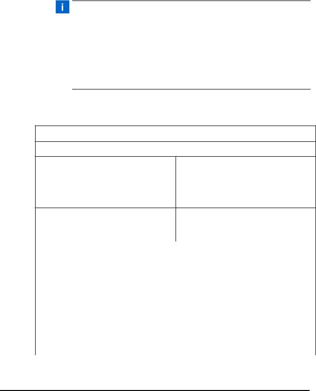
What you need help with or information about... |
Whom to Call |
At this Phone |
|
number |
|||
|
|
||
Information about new welding systems or components |
Your local Branson Rep or |
203-796-0400 |
|
Branson Customer Service |
Ext 384 |
||
|
|||
Application and Setup questions on the |
Welding Applications Lab |
203-796-0400 |
|
welding system |
Ext 368 |
||
|
|||
Application assistance on the Horns and |
ATG Lab |
203-796-0400 |
|
Tooling |
Ext 495 |
||
|
|||
Technical questions about the welding system |
Welding Product Support |
203-796-0400 |
|
Ext 355 |
|||
|
|
||
Technical questions about Horns and Tooling |
ATG Lab |
203-796-0400 |
|
Ext 495 |
|||
|
|
||
Ordering new parts |
Parts Store |
877-330-0406 |
|
RGA’s, Request for Repair, Status of a Repair |
Welding Repair Depart- |
877-330-0405 |
|
ment |
|||
|
|
||
System Automation/Hookup Information |
Product Support |
203-796-0400 |
|
Ext 355 |
|||
|
|
My Local Branson Representative’s name is:
__________________________________________________
I can reach this representative at:
___________________________________________________________________
1-14 |
100-214-275 Rev. 09 |

2000X ae Actuator |
Chapter 1: Safety and Support |
|
Instruction Manual |
Obtaining Replacement Parts |
|
|
|
|
1.5.4Pack and Ship the Equipment
1.Carefully pack the system in original packing material to avoid shipping damage. Plainly show the RGA number on the outside of cartons as well as inside the carton along with the reason for return. Make a list of all components packed in the box. KEEP YOUR MANUAL.
2.Return general repairs by any convenient method. Send priority repairs by air freight. Prepay the transportation charges FOB the repair site.
NOTE
Items that are sent Freight Collect will be refused.
_______________________________________________________________________
_______________________________________________________________________
_______________________________________________________________________
1.6 Obtaining Replacement Parts
You can reach Branson Parts Store at the following telephone numbers: Branson Part Store
direct telephone number: 877-330-0406 fax number: 877-330-0404
Many parts can be shipped the same day if ordered before 2:30 p.m., Eastern time.
A parts list is found in Chapter 7 of this manual, listing descriptions and EDP part numbers. If you need replacement parts, coordinate the following with your purchasing agent:
•Purchase order number
•‘Ship to’ information
•‘Bill to’ information
•Shipping instructions (air freight, truck, etc.)
•Any special instructions (for example, “Hold at the airport and call”). Be sure to give a name and phone number
•Contact name information
100-214-275 Rev. 09 |
1-15 |

Chapter 1: Safety and Support
Obtaining Replacement Parts
1-16 |
100-214-275 Rev. 09 |

2000X ae Actuator |
Chapter 2: Introduction to the 2000X ae Actuator |
|
Instruction Manual |
Models Covered |
|
|
|
|
Chapter 2: Introduction to the 2000X ae Actuator
2.1 |
Models Covered - - - - - |
- - |
- |
- |
- |
- |
- |
- |
- |
- |
- |
- |
- |
- |
- |
- |
- |
- - 2-1 |
|||
2.1.1 |
Power Supply Manual Set |
- |
- |
- |
- |
- |
- |
- |
- |
- |
- |
- |
- |
- |
- |
- |
- - 2-2 |
||||
2.1.2 |
Actuator Manual Set - |
- |
- |
- |
- |
- |
- |
- |
- |
- |
- |
- |
- |
- |
- |
- |
- |
- |
- - 2-2 |
||
2.2 |
Overview of this Model - |
- |
- |
- |
- |
- |
- |
- |
- |
- |
- |
- |
- |
- |
- |
- |
- |
- |
- - 2-3 |
||
2.3 |
Features of the System - |
- |
- |
- |
- |
- |
- |
- |
- |
- |
- |
- |
- |
- |
- |
- |
- |
- |
- - 2-4 |
||
2.4 |
Controls and Indicators - |
- |
- |
- |
- |
- |
- |
- |
- |
- |
- |
- |
- |
- |
- |
- |
- |
- |
- - 2-6 |
||
2.5 |
Welding Systems - |
- |
- - |
- - |
- |
- |
- |
- |
- |
- |
- |
- |
- |
- |
- |
- |
- |
- |
- |
- - 2-7 |
|
2.6 |
Glossary of Terms |
- |
- - |
- |
- |
- |
- |
- |
- |
- |
- |
- |
- |
- |
- |
- |
- |
- |
- |
- |
- - 2-8 |
The 2000X ae Actuator provides motion, force, power (from the power supply), and cooling air to the ultrasonic stack assembly. The 2000X ae Actuator is designed to work with a Branson 2000X-Series Power Supply.
2.1 Models Covered
This manual covers the Branson 2000X ae Actuator. The 2000X ae Actuator may be found in one of several configurations:
•An Actuator on a Column Support, Column and Ergonomic Base, also called a Stand on Base (as seen on the following page)
•An Actuator on a Column Support, Column and Mounting Hub, sometimes called a Stand on Hub
•An Actuator alone (not installed on a Column Support, and so on.). These are often used in custom or automated systems that provide a means of positioning the Actuator
This manual covers these configurations. A 2000X-series actuator requires a 2000X-series power supply to function, and that is covered in separate manuals and user documents.
Figure 2-1 shows a Branson 2000X ae Actuator mounted on a column support which, in turn is mounted on a column, and is supported by the ergonomic base.
100-214-275 Rev. 09 |
2-1 |

Chapter 2: Introduction to the 2000X ae Actuator
Models Covered
Figure 2.1 Left Side View of the 2000X ae Actuator
2000X ae/aed Actuator |
2000X 15kHz ae/aed Actuator |
2.1.1 Power Supply Manual Set
The following documentation is available for the Branson 2000X-series Power Supplies that are compatible with the 2000X ae Actuator:
•2000X ea Power Supply Instruction Manual (EDP 100-214-278)
•2000-Series Installation Guide (EDP 100-214-226)
•2000X ea Quick Start User’s Guide (EDP 100-214-281)
2.1.2 Actuator Manual Set
The following documentation is available for the Branson 2000X ae Actuator:
•2000 Series Installation Guide (EDP 100-214-226)
•2000X ae Actuator Instruction Manual (EDP 100-214-275)
2-2 |
100-214-275 Rev. 09 |
Loading...