


Original Instructions
100-412-183 - REV. 13
DCX S
Power Supply
Operating Manual
Branson Ultrasonics Corporation
41 Eagle Road
Danbury, CT 06813-1961 USA (203) 796-0400 http://www.bransonultrasonics.com

Manual Change Information
At Branson, we strive to maintain our position as the leader in ultrasonics plastics joining, metal welding, cleaning and related technologies by continually improving our circuits and components in our equipment. These improvements are incorporated as soon as they are developed and thoroughly tested.
Information concerning any improvements will be added to the appropriate technical documentation at its next revision and printing. Therefore, when requesting service assistance for specific units, note the Revision information found on the cover of this document, and refer to the printing date which appears at the bottom of this page.
Copyright and Trademark Notice
Copyright © 2017 Branson Ultrasonics Corporation. All rights reserved. Contents of this publication may not be reproduced in any form without the written permission of Branson Ultrasonics Corporation.
Mylar is a registered trademark of DuPont Teijin Films.
Loctite is a registered trademark of Loctite Corporation.
WD-40 is a registered trademark of WD-40 Company.
Windows 7, Windows Vista, and Windows XP are registered trademarks of Microsoft Corporation
Other trademarks and service marks mentioned herein are held by their respective owners.
ii |
100-412-183 REV. 13 |

Foreword
Congratulations on your choice of a Branson Ultrasonics Corporation system!
The Branson DCX S Power Supply system is process equipment for the joining of plastic parts using ultrasonic energy. It is the newest generation of product using this sophisticated technology for a variety of customer applications. This Operating Manual is part of the documentation set for this system, and should be kept with the equipment.
Thank you for choosing Branson!
Introduction
This manual is arranged into several structured chapters which will help you find the information you may need to know to safely handle, install, set up, program, operate, and/or maintain this product. Please refer to the Table Of Contents and/or the Index of this manual to find the information you may be looking for. In the event you require additional assistance or information, please contact our Product Support department (see 1.3 How to Contact Branson for information on how to contact them) or your local Branson representative.
100-412-183 REV. 13 |
iii |

|
|
|
|
|
|
|
|
|
iv |
100-412-183 REV. 13 |
|

Table Of Contents
Chapter 1:Safety and Support |
|
|
1.1 |
Safety Requirements and Warnings . . . . . . . . . . . . . . . . . . . . . . . . . . . . . . . . . . |
. 2 |
1.2 |
General Precautions. . . . . . . . . . . . . . . . . . . . . . . . . . . . . . . . . . . . . . . . . . . . . |
. 5 |
1.3 |
How to Contact Branson. . . . . . . . . . . . . . . . . . . . . . . . . . . . . . . . . . . . . . . . . . |
. 7 |
Chapter 2:Introduction |
|
|
2.1 |
Models Covered. . . . . . . . . . . . . . . . . . . . . . . . . . . . . . . . . . . . . . . . . . . . . . . . |
.14 |
2.2 |
Compatibility with other Branson Products . . . . . . . . . . . . . . . . . . . . . . . . . . . . . |
.17 |
2.3 |
Features. . . . . . . . . . . . . . . . . . . . . . . . . . . . . . . . . . . . . . . . . . . . . . . . . . . . . |
.18 |
2.4 |
Controls and Indicators . . . . . . . . . . . . . . . . . . . . . . . . . . . . . . . . . . . . . . . . . . |
.20 |
2.5 |
Welding Systems. . . . . . . . . . . . . . . . . . . . . . . . . . . . . . . . . . . . . . . . . . . . . . . |
.23 |
2.6 |
Glossary of Terms . . . . . . . . . . . . . . . . . . . . . . . . . . . . . . . . . . . . . . . . . . . . . . |
.24 |
Chapter 3:Delivery and Handling |
|
|
3.1 |
Shipping and Handling . . . . . . . . . . . . . . . . . . . . . . . . . . . . . . . . . . . . . . . . . . . |
.28 |
3.2 |
Receiving . . . . . . . . . . . . . . . . . . . . . . . . . . . . . . . . . . . . . . . . . . . . . . . . . . . . |
.29 |
3.3 |
Unpacking the Power Supply. . . . . . . . . . . . . . . . . . . . . . . . . . . . . . . . . . . . . . . |
.30 |
3.4 |
Take Inventory of Small Parts . . . . . . . . . . . . . . . . . . . . . . . . . . . . . . . . . . . . . . |
.31 |
3.5 |
Returning Equipment . . . . . . . . . . . . . . . . . . . . . . . . . . . . . . . . . . . . . . . . . . . . |
.32 |
Chapter 4:Technical Specifications |
|
|
4.1 |
Technical Specifications . . . . . . . . . . . . . . . . . . . . . . . . . . . . . . . . . . . . . . . . . . |
.34 |
4.2 |
Physical Description . . . . . . . . . . . . . . . . . . . . . . . . . . . . . . . . . . . . . . . . . . . . . |
.36 |
4.3 |
Declaration of Conformity. . . . . . . . . . . . . . . . . . . . . . . . . . . . . . . . . . . . . . . . . |
.37 |
4.4 |
Standard Modules and Components . . . . . . . . . . . . . . . . . . . . . . . . . . . . . . . . . . |
.38 |
Chapter 5:Installation and Setup |
|
|
5.1 |
About Installation . . . . . . . . . . . . . . . . . . . . . . . . . . . . . . . . . . . . . . . . . . . . . . |
.42 |
5.2 |
Installation Requirements. . . . . . . . . . . . . . . . . . . . . . . . . . . . . . . . . . . . . . . . . |
.43 |
5.3 |
Installation Steps . . . . . . . . . . . . . . . . . . . . . . . . . . . . . . . . . . . . . . . . . . . . . . |
.49 |
5.4 |
Power Supply Configuration . . . . . . . . . . . . . . . . . . . . . . . . . . . . . . . . . . . . . . . |
.66 |
5.5 |
Assembling the Acoustic Stack . . . . . . . . . . . . . . . . . . . . . . . . . . . . . . . . . . . . . |
.67 |
5.6 |
Converter Cooling . . . . . . . . . . . . . . . . . . . . . . . . . . . . . . . . . . . . . . . . . . . . . . |
.72 |
5.7 |
Testing the Installation . . . . . . . . . . . . . . . . . . . . . . . . . . . . . . . . . . . . . . . . . . |
.74 |
5.8 |
Still Need Help?. . . . . . . . . . . . . . . . . . . . . . . . . . . . . . . . . . . . . . . . . . . . . . . . |
.75 |
Chapter 6:Converters and Boosters |
|
|
6.1 |
Converters and Boosters . . . . . . . . . . . . . . . . . . . . . . . . . . . . . . . . . . . . . . . . . |
.78 |
Chapter 7:Operation |
|
|
7.1 |
Activating Ultrasonic Power. . . . . . . . . . . . . . . . . . . . . . . . . . . . . . . . . . . . . . . . |
.90 |
7.2 |
Setting the Amplitude . . . . . . . . . . . . . . . . . . . . . . . . . . . . . . . . . . . . . . . . . . . |
.91 |
7.3 |
Resetting the Power Supply Alarms . . . . . . . . . . . . . . . . . . . . . . . . . . . . . . . . . . |
.93 |
7.4 |
Configuring the Power Supply Registers . . . . . . . . . . . . . . . . . . . . . . . . . . . . . . . |
.94 |
7.5 |
LCD Bar Graph . . . . . . . . . . . . . . . . . . . . . . . . . . . . . . . . . . . . . . . . . . . . . . . . |
.98 |
7.6 |
Web Page Interface . . . . . . . . . . . . . . . . . . . . . . . . . . . . . . . . . . . . . . . . . . . . . |
101 |
7.7 |
Ultrasonics Test Procedure . . . . . . . . . . . . . . . . . . . . . . . . . . . . . . . . . . . . . . . . |
106 |
100-412-183 REV. 13 |
v |

Chapter 8:Maintenance |
|
|
8.1 |
General Maintenance Considerations . . . . . . . . . . . . . . . . . . . . . . . . . . . . . . . . . |
112 |
8.2 |
Preventive Maintenance. . . . . . . . . . . . . . . . . . . . . . . . . . . . . . . . . . . . . . . . . . |
114 |
8.3 |
Calibration . . . . . . . . . . . . . . . . . . . . . . . . . . . . . . . . . . . . . . . . . . . . . . . . . . . |
120 |
8.4 |
Recommended Spare Stock . . . . . . . . . . . . . . . . . . . . . . . . . . . . . . . . . . . . . . . |
121 |
8.5 |
Circuit Diagram . . . . . . . . . . . . . . . . . . . . . . . . . . . . . . . . . . . . . . . . . . . . . . . |
127 |
8.6 |
Troubleshooting . . . . . . . . . . . . . . . . . . . . . . . . . . . . . . . . . . . . . . . . . . . . . . . |
128 |
8.7 |
Cold Start Procedure . . . . . . . . . . . . . . . . . . . . . . . . . . . . . . . . . . . . . . . . . . . . |
133 |
Appendix A:Timing Diagrams |
|
|
A.1 |
Timing Diagrams . . . . . . . . . . . . . . . . . . . . . . . . . . . . . . . . . . . . . . . . . . . . . . |
136 |
Appendix B:Signal Diagrams |
|
|
B.1 |
Signal Diagrams . . . . . . . . . . . . . . . . . . . . . . . . . . . . . . . . . . . . . . . . . . . . . . . |
138 |
vi |
100-412-183 REV. 13 |

List Of Figures
Chapter 1:Safety and Support
Figure 1.1 Safety-related Labels Found on the DCX S Power Supply (Horizontal) . . . . . . . . . . . 3 Figure 1.2 Safety-related Labels found on the DCX S Power Supply (Vertical) . . . . . . . . . . . . . 4
Chapter 2:Introduction
Figure 2.1 The DCX S Power Supply (Horizontal) . . . . . . . . . . . . . . . . . . . . . . . . . . . . . . . . .15 Figure 2.2 The DCX S Power Supply (Vertical) . . . . . . . . . . . . . . . . . . . . . . . . . . . . . . . . . . .15 Figure 2.3 DCX S Power Supply Front Panel Controls and Indicators . . . . . . . . . . . . . . . . . . . .20 Figure 2.4 LCD Description . . . . . . . . . . . . . . . . . . . . . . . . . . . . . . . . . . . . . . . . . . . . . . . .21 Figure 2.5 DCX S Power Supply Back Panel (Horizontal) . . . . . . . . . . . . . . . . . . . . . . . . . . . .22 Figure 2.6 DCX S Power Supply Bottom Panel (Vertical) . . . . . . . . . . . . . . . . . . . . . . . . . . . .22
Chapter 3:Delivery and Handling
Chapter 4:Technical Specifications
Figure 4.1 Declaration of Conformity. . . . . . . . . . . . . . . . . . . . . . . . . . . . . . . . . . . . . . . . . .37 Figure 4.2 System Block Diagram . . . . . . . . . . . . . . . . . . . . . . . . . . . . . . . . . . . . . . . . . . . .38
Chapter 5:Installation and Setup
Figure 5.1 DCX S Power Supply Benchtop Dimensional Drawing . . . . . . . . . . . . . . . . . . . . . . .44
Figure 5.2 DCX S Power Supply Vertical Mount Dimensional Drawing (400 W, 750 W and 800 W) 45
Figure 5.3 DCX S Power Supply Vertical Mount Dimensional Drawing (1.25 kW and 1.5 kW) . . .46 Figure 5.4 DCX S Power Supply Vertical Mount Dimensional Drawing (2.5 kW and 4 kW) . . . . .47 Figure 5.5 LCD Viewing Angle . . . . . . . . . . . . . . . . . . . . . . . . . . . . . . . . . . . . . . . . . . . . . .51 Figure 5.6 DCX S Power Supply Connections (Horizontal Model) . . . . . . . . . . . . . . . . . . . . . . .52 Figure 5.7 DCX S Power Supply Connections (Vertical Model) . . . . . . . . . . . . . . . . . . . . . . . .53 Figure 5.8 User I/O Cable Identification and Wire Color Diagram . . . . . . . . . . . . . . . . . . . . . .55 Figure 5.9 Typical Digital I/O Wiring Examples . . . . . . . . . . . . . . . . . . . . . . . . . . . . . . . . . . .62 Figure 5.10 Typical Analog I/O Wiring Examples. . . . . . . . . . . . . . . . . . . . . . . . . . . . . . . . . . .62 Figure 5.11 RF Cable Connection . . . . . . . . . . . . . . . . . . . . . . . . . . . . . . . . . . . . . . . . . . . . .63 Figure 5.12 Assembling the Acoustic Stack . . . . . . . . . . . . . . . . . . . . . . . . . . . . . . . . . . . . . .68 Figure 5.13 Connecting Tip to Horn . . . . . . . . . . . . . . . . . . . . . . . . . . . . . . . . . . . . . . . . . . .71
Chapter 6:Converters and Boosters
Figure 6.1 20 kHz CH-20S Converter Dimensions . . . . . . . . . . . . . . . . . . . . . . . . . . . . . . . . .79 Figure 6.2 20 kHz Booster Dimensions . . . . . . . . . . . . . . . . . . . . . . . . . . . . . . . . . . . . . . . .80 Figure 6.3 20 kHz Converter/Booster/Horn, Typical Dimensions . . . . . . . . . . . . . . . . . . . . . . .81 Figure 6.4 30 kHz Converter Dimensions . . . . . . . . . . . . . . . . . . . . . . . . . . . . . . . . . . . . . . .82 Figure 6.5 30 kHz Booster Dimensions . . . . . . . . . . . . . . . . . . . . . . . . . . . . . . . . . . . . . . . .83 Figure 6.6 30 kHz Converter/Booster/Horn, Typical Dimensions . . . . . . . . . . . . . . . . . . . . . . .84 Figure 6.7 40 kHz, 4TR Converter Dimensions . . . . . . . . . . . . . . . . . . . . . . . . . . . . . . . . . . .85 Figure 6.8 40 kHz Booster Dimensions . . . . . . . . . . . . . . . . . . . . . . . . . . . . . . . . . . . . . . . .86 Figure 6.9 40 kHz Converter/Booster/Horn, Typical Dimensions . . . . . . . . . . . . . . . . . . . . . . .87
Chapter 7:Operation
Figure 7.1 LCD at Power Up . . . . . . . . . . . . . . . . . . . . . . . . . . . . . . . . . . . . . . . . . . . . . . . .91 Figure 7.2 LCD when in External Amplitude Control Mode . . . . . . . . . . . . . . . . . . . . . . . . . . .92 Figure 7.3 Test Connections . . . . . . . . . . . . . . . . . . . . . . . . . . . . . . . . . . . . . . . . . . . . . . . 108
100-412-183 REV. 13 |
vii |

Chapter 8:Maintenance
Figure 8.1 Reconditioning Stack Mating Surfaces . . . . . . . . . . . . . . . . . . . . . . . . . . . . . . . . 116 Figure 8.2 Interconnect Diagram, Power Supply . . . . . . . . . . . . . . . . . . . . . . . . . . . . . . . . 127
Appendix A:Timing Diagrams
Figure A.1 Weld Cycle. . . . . . . . . . . . . . . . . . . . . . . . . . . . . . . . . . . . . . . . . . . . . . . . . . . 136
Figure A.2 Weld Cycle. . . . . . . . . . . . . . . . . . . . . . . . . . . . . . . . . . . . . . . . . . . . . . . . . . . 136
Figure A.3 Weld Cycle. . . . . . . . . . . . . . . . . . . . . . . . . . . . . . . . . . . . . . . . . . . . . . . . . . . 136
Appendix B:Signal Diagrams
Figure B.1 Continuous Mode . . . . . . . . . . . . . . . . . . . . . . . . . . . . . . . . . . . . . . . . . . . . . . 138
viii |
100-412-183 REV. 13 |

List Of Tables
Chapter 1:Safety and Support
Table 1.1 Authorized Service Center (North America) . . . . . . . . . . . . . . . . . . . . . . . . . . . . . 7 Table 1.2 Authorized Service Centers (South America). . . . . . . . . . . . . . . . . . . . . . . . . . . . . 7 Table 1.3 Authorized Service Centers (Asia) . . . . . . . . . . . . . . . . . . . . . . . . . . . . . . . . . . . . 8 Table 1.4 Authorized Service Centers (Europe) . . . . . . . . . . . . . . . . . . . . . . . . . . . . . . . . . .10
Chapter 2:Introduction
Table 2.1 Models Covered In This Manual . . . . . . . . . . . . . . . . . . . . . . . . . . . . . . . . . . . . . .14 Table 2.2 Power Supply Compatibility with Branson Converters. . . . . . . . . . . . . . . . . . . . . . .17 Table 2.3 DCX S Power Supply Front Panel Controls and Indicators . . . . . . . . . . . . . . . . . . . .20 Table 2.4 LCD Description . . . . . . . . . . . . . . . . . . . . . . . . . . . . . . . . . . . . . . . . . . . . . . . .21 Table 2.5 Connections to the DCX S Power Supply. . . . . . . . . . . . . . . . . . . . . . . . . . . . . . . .22
Chapter 3:Delivery and Handling
Table 3.1 Shipping Specifications. . . . . . . . . . . . . . . . . . . . . . . . . . . . . . . . . . . . . . . . . . . .28 Table 3.2 Inspect the Power Supply . . . . . . . . . . . . . . . . . . . . . . . . . . . . . . . . . . . . . . . . . .29 Table 3.3 Unpacking the Power Supply. . . . . . . . . . . . . . . . . . . . . . . . . . . . . . . . . . . . . . . .30 Table 3.4 Small Parts included (=x): Power Supply Assemblies . . . . . . . . . . . . . . . . . . . . . . .31 Table 3.5 DCX S Power Supply System Cables . . . . . . . . . . . . . . . . . . . . . . . . . . . . . . . . . .31
Chapter 4:Technical Specifications
Table 4.1 Environmental Specifications . . . . . . . . . . . . . . . . . . . . . . . . . . . . . . . . . . . . . . .34 Table 4.2 Electrical Input Operating Voltages . . . . . . . . . . . . . . . . . . . . . . . . . . . . . . . . . . .34 Table 4.3 Input Current and Circuit Breaker Specifications . . . . . . . . . . . . . . . . . . . . . . . . . .34 Table 4.4 Continuous Duty Max. Power . . . . . . . . . . . . . . . . . . . . . . . . . . . . . . . . . . . . . . .35 Table 4.5 Dimension and Weight of DCX S Power Supply . . . . . . . . . . . . . . . . . . . . . . . . . . .36
Chapter 5:Installation and Setup
Table 5.1 Environmental Requirements . . . . . . . . . . . . . . . . . . . . . . . . . . . . . . . . . . . . . . .48 Table 5.2 Input Current and Circuit Breaker Specifications . . . . . . . . . . . . . . . . . . . . . . . . . .48 Table 5.3 DCX S Power Supply Connections (Horizontal Model) . . . . . . . . . . . . . . . . . . . . . . .52 Table 5.4 DCX S Power Supply Connections (Vertical Model). . . . . . . . . . . . . . . . . . . . . . . . .53 Table 5.5 User I/O Cable Pin assignments . . . . . . . . . . . . . . . . . . . . . . . . . . . . . . . . . . . . .56 Table 5.6 Available Digital Input Functions . . . . . . . . . . . . . . . . . . . . . . . . . . . . . . . . . . . . .57 Table 5.7 Available Digital Output Functions . . . . . . . . . . . . . . . . . . . . . . . . . . . . . . . . . . . .58 Table 5.8 Available Analog Input Functions. . . . . . . . . . . . . . . . . . . . . . . . . . . . . . . . . . . . .59 Table 5.9 Available Analog Output Functions. . . . . . . . . . . . . . . . . . . . . . . . . . . . . . . . . . . .60 Table 5.10 Default User I/O Connector Pin Assignments. . . . . . . . . . . . . . . . . . . . . . . . . . . . .61 Table 5.11 RF Cable Connections . . . . . . . . . . . . . . . . . . . . . . . . . . . . . . . . . . . . . . . . . . . .63 Table 5.12 Input Power Connection . . . . . . . . . . . . . . . . . . . . . . . . . . . . . . . . . . . . . . . . . . .64 Table 5.13 Acoustic Stack Description . . . . . . . . . . . . . . . . . . . . . . . . . . . . . . . . . . . . . . . . .68 Table 5.14 Stack Torque Values . . . . . . . . . . . . . . . . . . . . . . . . . . . . . . . . . . . . . . . . . . . . .68 Table 5.15 Tools . . . . . . . . . . . . . . . . . . . . . . . . . . . . . . . . . . . . . . . . . . . . . . . . . . . . . . . .69 Table 5.16 20 kHz System . . . . . . . . . . . . . . . . . . . . . . . . . . . . . . . . . . . . . . . . . . . . . . . . .70 Table 5.17 30 kHz System . . . . . . . . . . . . . . . . . . . . . . . . . . . . . . . . . . . . . . . . . . . . . . . . .70 Table 5.18 40 kHz System . . . . . . . . . . . . . . . . . . . . . . . . . . . . . . . . . . . . . . . . . . . . . . . . .70 Table 5.19 Tip to Horn Values . . . . . . . . . . . . . . . . . . . . . . . . . . . . . . . . . . . . . . . . . . . . . . .71 Table 5.20 Continuous Duty Max. Power & Full Power Duty Cycle . . . . . . . . . . . . . . . . . . . . . .72 Table 5.21 Converter Cooling Procedure. . . . . . . . . . . . . . . . . . . . . . . . . . . . . . . . . . . . . . . .73
100-412-183 REV. 13 |
ix |

Chapter 6:Converters and Boosters
Table 6.1 20 kHz CH-20S Converter Dimensions. . . . . . . . . . . . . . . . . . . . . . . . . . . . . . . . . 79 Table 6.2 20 kHz Booster Dimensions . . . . . . . . . . . . . . . . . . . . . . . . . . . . . . . . . . . . . . . . 80 Table 6.3 20 kHz Converter/Booster/Horn, Typical Dimensions. . . . . . . . . . . . . . . . . . . . . . . 81 Table 6.4 30 kHz Converter Dimensions . . . . . . . . . . . . . . . . . . . . . . . . . . . . . . . . . . . . . . 82 Table 6.5 30 kHz Booster Dimensions . . . . . . . . . . . . . . . . . . . . . . . . . . . . . . . . . . . . . . . . 83 Table 6.6 30 kHz Converter/Booster/Horn, Typical Dimensions. . . . . . . . . . . . . . . . . . . . . . . 84 Table 6.7 40 kHz, 4TR Converter Dimensions . . . . . . . . . . . . . . . . . . . . . . . . . . . . . . . . . . . 85 Table 6.8 40 kHz Booster Dimensions . . . . . . . . . . . . . . . . . . . . . . . . . . . . . . . . . . . . . . . . 86 Table 6.9 40 kHz Converter/Booster/Horn, Typical Dimensions. . . . . . . . . . . . . . . . . . . . . . . 87
Chapter 7:Operation
Table 7.1 Setting the Amplitude Using the Front Panel Controls . . . . . . . . . . . . . . . . . . . . . . 91 Table 7.2 Resetting the DCX S Power Supply . . . . . . . . . . . . . . . . . . . . . . . . . . . . . . . . . . . 93 Table 7.3 Steps to configure the Power Supply Registers . . . . . . . . . . . . . . . . . . . . . . . . . . . 94 Table 7.4 Power Supply Registers . . . . . . . . . . . . . . . . . . . . . . . . . . . . . . . . . . . . . . . . . . . 96 Table 7.5 Power Bar Graph Interpretation Examples . . . . . . . . . . . . . . . . . . . . . . . . . . . . . . 98 Table 7.6 Frequency Bar-Graph Interpretation - 20 kHz (50 Hz Segment) . . . . . . . . . . . . . . . 99 Table 7.7 Frequency Bar-Graph Interpretation - 30 kHz (76 Hz Segment) . . . . . . . . . . . . . . . 99 Table 7.8 Frequency Bar-Graph Interpretation - 40 kHz (100 Hz/Segment) . . . . . . . . . . . . . . 99 Table 7.9 Frequency Bar Graph Interpretation Examples . . . . . . . . . . . . . . . . . . . . . . . . . . 100 Table 7.10 Power Supply Ultrasonic Test Procedure (Front Panel). . . . . . . . . . . . . . . . . . . . . 107 Table 7.11 Power Supply Ultrasonic Test Procedure (User I/O). . . . . . . . . . . . . . . . . . . . . . . 107 Table 7.12 Power Supply Ultrasonic Test Procedure (Web Page Interface) . . . . . . . . . . . . . . . 108
Chapter 8:Maintenance
Table 8.1 Stack Reconditioning Procedure . . . . . . . . . . . . . . . . . . . . . . . . . . . . . . . . . . . . 115 Table 8.2 Reconditioning Stack Mating Surfaces . . . . . . . . . . . . . . . . . . . . . . . . . . . . . . . . 116 Table 8.3 Stack Torque Values . . . . . . . . . . . . . . . . . . . . . . . . . . . . . . . . . . . . . . . . . . . . 117 Table 8.4 Stack Reassembly for a 20 kHz System . . . . . . . . . . . . . . . . . . . . . . . . . . . . . . . 117 Table 8.5 Stack Reassembly for a 30 kHz System . . . . . . . . . . . . . . . . . . . . . . . . . . . . . . . 118 Table 8.6 Stack Reassembly for a 40 kHz System . . . . . . . . . . . . . . . . . . . . . . . . . . . . . . . 118 Table 8.7 Stud Torque Values. . . . . . . . . . . . . . . . . . . . . . . . . . . . . . . . . . . . . . . . . . . . . 119 Table 8.8 DCX S Power Supply System Cables . . . . . . . . . . . . . . . . . . . . . . . . . . . . . . . . . 121 Table 8.9 Suggested Spares. . . . . . . . . . . . . . . . . . . . . . . . . . . . . . . . . . . . . . . . . . . . . . 122 Table 8.10 Converters Compatible with the DCX S Power Supply . . . . . . . . . . . . . . . . . . . . . 123 Table 8.11 DCX S Power Supply Compatible Boosters . . . . . . . . . . . . . . . . . . . . . . . . . . . . . 124 Table 8.12 Other Items used with the DCX S Power Supply . . . . . . . . . . . . . . . . . . . . . . . . . 126 Table 8.13 Troubleshooting . . . . . . . . . . . . . . . . . . . . . . . . . . . . . . . . . . . . . . . . . . . . . . . 128 Table 8.14 Troubleshooting Common Electrical Problems. . . . . . . . . . . . . . . . . . . . . . . . . . . 129 Table 8.15 Troubleshooting Fan/Power Switch Problems . . . . . . . . . . . . . . . . . . . . . . . . . . . 130 Table 8.16 Troubleshooting Ultrasonic Power Problems . . . . . . . . . . . . . . . . . . . . . . . . . . . . 131 Table 8.17 Troubleshooting Weld Cycle Problems . . . . . . . . . . . . . . . . . . . . . . . . . . . . . . . . 132 Table 8.18 Steps to Perform a Cold Start. . . . . . . . . . . . . . . . . . . . . . . . . . . . . . . . . . . . . . 133
Appendix A:Timing Diagrams
Appendix B:Signal Diagrams
x |
100-412-183 REV. 13 |
Chapter 1: Safety and Support
1.1 Safety Requirements and Warnings . . . . . . . . . . . . . . . . . . . . . . . . . . . 2 1.2 General Precautions . . . . . . . . . . . . . . . . . . . . . . . . . . . . . . . . . . . . . . . 5 1.3 How to Contact Branson. . . . . . . . . . . . . . . . . . . . . . . . . . . . . . . . . . . . 7
100-412-183 REV. 13 |
1 |

1.1Safety Requirements and Warnings
This chapter contains an explanation of the different Safety Notice symbols and icons found both in this manual and on the product itself and provides additional safety information for ultrasonic welding. This chapter also describes how to contact Branson for assistance.
1.1.1Symbols Found in this Manual
These symbols used throughout this manual warrant special attention:
DANGER |
Indicates an immediate danger |
|
|
|
If these risks are not avoided, death or severe injury will be the |
|
result. |
|
|
WARNING Indicates a possible danger
If these risks are not avoided, death or severe injury might result.
CAUTION |
Indicates a possible danger |
|
|
If these risks are not avoided, slight or minor injury might result.
NOTICE |
Indicates a possible damaging situation |
|
|
If this situation is not avoided, the system or something in its vicinity might be damaged.
Application types and other important or useful information are emphasized.
2 |
100-412-183 REV. 13 |

1.1.2Symbols Found on the Product
The DCX S Power Supply has several safety-related labels on it to indicate the presence of hazardous voltages inside the unit.
Figure 1.1 Safety-related Labels Found on the DCX S Power Supply (Horizontal)
100-412-183 REV. 13 |
3 |

Figure 1.2 Safety-related Labels found on the DCX S Power Supply (Vertical)
4 |
100-412-183 REV. 13 |

1.2General Precautions
Take the following precautions before servicing the power supply:
•Be sure the power switch is in the off position before making any electrical connections
•To prevent the possibility of an electrical shock, always plug the power supply into a grounded power source
•To prevent the possibility of an electrical shock, ground the power supply by securing an 8 gage grounded conductor to the ground screw located next to the air outlet
•Power supplies produce high voltage. Before working on the power supply assembly, do the following:
Turn off the power supply; Unplug main power; and
Allow at least 2 minutes for capacitors to discharge
•High voltage is present in the power supply. Do not operate with the cover removed
•High line voltages exist in the ultrasonic power supply assembly. Common points are tied to circuit reference, not chassis ground. Therefore, use only non-grounded, battery-powered multimeters when testing the power supply assembly. Using other types of test equipment can present a shock hazard
•Keep hands from under the horn. Down force (pressure) and ultrasonic vibrations can cause injury
•Do not cycle the welding system if either the RF cable or converter is disconnected
•When using larger horns, avoid situations where fingers could be pinched between the horn and the fixture
•Ensure power supply installation is performed by qualified personnel and in accordance with local standards and regulations
CAUTION |
Loud Noise Hazard |
|
|
Sound level and frequency of the noise emitted during the ultrasonic assembly process may depend upon a. type of application, b. size, shape and composition of the material being assembled, c. shape and material of the holding fixture, d. welder setup parameters and e. tool design.
Some parts vibrate at an audible frequency during the process. Some or all of these factors may result in an uncomfortable noise being emitted during the process.
In such cases operators may need to be provided with personal protective equipment. See 29 CFR (Code of Federal Regulations) 1910.95 Occupational Noise Exposure.
100-412-183 REV. 13 |
5 |
1.2.1Intended Use of the System
The DCX S Power Supply and components are designed to be used as part of an ultrasonic welding system. These are designed for a wide variety of welding or processing applications.
1.2.2Emissions
When being processed, certain plastic materials can emit toxic fumes, gases or other emissions that can be hazardous to the operator’s health. Where such materials are processed, proper ventilation of the workstation is required. Check your materials suppliers for recommended protection when processing their materials.
CAUTION |
Corrosive Material Hazard |
|
|
|
Processing of many materials, such as PVC, can be hazardous to an |
|
operator’s health and could cause corrosion/damage to the |
|
equipment. Use proper ventilation and take protective measures. |
|
|
1.2.3Setting up the Workplace
Measures for setting up a workplace for safe operation of the ultrasonic welder are outlined in Chapter 5: Installation and Setup
1.2.4Regulatory Compliance
This product meets electrical safety requirements and EMC (Electromagnetic Compliance) requirements for North America and the European Union.
6 |
100-412-183 REV. 13 |

1.3How to Contact Branson
Branson is here to help you. We appreciate your business and are interested in helping you successfully use our products. To contact Branson for help, use the following telephone numbers, or contact the office nearest you.
1.3.1Authorized Service Center (North America)
Table 1.1 Authorized Service Center (North America)
Name |
Address |
Tel/Fax Number |
|
|
|
Branson Ultrasonics Corp. |
41 Eagle Road, Commerce |
Tel: 1-203-796-0400 |
Global Headquarters |
Park, |
Fax: 1-203-796-0593 |
United States |
Danbury CT 06813-1961 |
info@bransonultrasonics.com |
|
|
|
1.3.2Authorized Service Centers (South America)
Table 1.2 Authorized Service Centers (South America)
Name |
Address |
Tel/Fax Number |
|
|
|
|
|
Intersonic |
Av. Cramer 2361 1C |
Tel: 011-54-11-4781-2327 |
|
Argentina |
Buenos Aires 1428 |
Fax: 011-54-11-4782-2412 |
|
|
|
|
|
Branson do Brasil |
Rua Goiatuba, 81 |
Tel: 55-11-4208-1652 |
|
Brasil |
06465-300 – Barueri / SP |
||
|
|||
|
|
|
100-412-183 REV. 13 |
7 |

1.3.3Authorized Service Centers (Asia)
Table 1.3 Authorized Service Centers (Asia)
Name |
Address |
Tel/Fax Number |
|
|
|
|
|
Branson Ultrasonics |
528 Rong Le Dong Road, |
Tel: 86-21-3781-0588 |
|
(Shanghai) Co. Ltd. – |
Song Jiang |
Fax: 86-21-5774-5100 |
|
China Headquarters |
Song Jiang Industry Zone |
||
China |
CN-Shanghai, 201613 PRC |
c.service@emerson.com |
|
|
|
|
|
|
Room 216, Flat B, 12 Hong |
|
|
|
Da North Road, |
|
|
Branson Ultrasonics Co. |
Chuangxin Technological |
Tel: 86-10-6787-7806 |
|
Ltd. Beijing Office |
Mansion Beijing Department |
Fax: 86-10-6787-3378 |
|
|
Area. |
|
|
|
Beijing 100176 PRC |
|
|
|
|
|
|
Branson Ultrasonics Co. |
|
Tel: 86-22-2732-5233 |
|
Ltd. Tianjin Office |
|
Fax: 86-22-2732-3581 |
|
|
|
|
|
Branson Ultrasonics Co. |
|
Tel: 86-769-8541-0736 |
|
Ltd. Dongguan Office |
|
Fax: 86-769-8541-0735 |
|
|
|
|
|
Branson Ultrasonics Co. |
|
Tel: 86-512-6295-3652 |
|
Ltd. Suzhou Office |
|
Fax: 86-512-6295-3651 |
|
|
|
|
|
Branson Ultrasonics Asia |
Flat A, 5/F Pioneer Building |
Tel: 852-2790-3393 |
|
213 Wai Yip Street, Kwung |
|||
Pacific Co. Ltd. |
Fax: 852-2341-2716 |
||
Hong Kong Office |
Tong |
info@emerson.com |
|
Kowloon, Hong Kong |
|||
|
|
||
|
|
|
|
Branson Ultrasonics |
8/35, Marol Co-Op Industrial |
|
|
|
|
||
Div. of Emerson Electric |
Estate |
Tel: 91-22-2850-5570 |
|
Co. P. Ltd. “Ajanta |
M.V. Road, Andheri (East) |
Fax: 91-22-2850-8681 |
|
House” |
|||
India |
Mumbai 400 059, India |
|
|
|
|
||
|
|
|
|
Branson Ultrasonics |
4-3-14 Okada, Atsugi-Shi |
|
|
Japan Headquarters |
Tel: 81-46-228-2881 |
||
Kanagawa 243-0021 |
|||
Division of Emerson |
Fax: 81-46-288-8892 |
||
Japan |
|||
Japan Ltd. |
|
||
|
|
||
|
|
|
|
|
#803, 8F Dongil Techno |
|
|
|
Town |
|
|
Branson Korea Co., Ltd. |
823, Kwan Yang-2dong, |
Tel: 82-1577-0631 |
|
Korea |
Dong An-gu |
Fax: 82-31-422-9572 |
|
An Yang-si, Kyung Ki-do, |
|||
|
|
||
|
431-062 Korea |
|
|
|
|
|
8 |
100-412-183 REV. 13 |

Table 1.3 Authorized Service Centers (Asia)
Name |
Address |
Tel/Fax Number |
|
|
|
|
|
|
No. 20, Jalan Rajawali 3, |
|
|
Branson Ultrasonics |
Puchong Jaya Industrial |
|
|
Div. of Emerson Elec (M) |
Park |
Tel: 603-8076-8608 |
|
Sdn Bhd. |
Batu 8, Jalang Puchong |
Fax: 603-8076-8302 |
|
Malaysia |
47170 Puchong, Selangor |
|
|
|
Malaysia |
|
|
|
|
|
|
|
Emerson Building |
|
|
Branson Ultrasonics |
104 Laguna Blvd. |
Tel: 63-49-502-8860 |
|
Laguna Technopark Inc. |
Fax: 63-49-502-8860 |
||
Philippines |
|||
Sta. Rosa, Laguna, 4026 |
Mobile: 63-917-5372072 |
||
|
|||
|
Philippines |
|
|
|
|
|
|
Branson Ultrasonics |
10 Pandan Crescent |
Tel: 65-6891-7600 |
|
#03-06 UE Tech Park LL3 |
|||
Singapore |
Fax: 65-6873-7882 |
||
Singapore 128466 |
|||
|
|
||
|
|
|
|
|
Div. of Emerson Electric |
|
|
|
(Taiwan) Co. Ltd. |
|
|
Branson Ultraschall |
5F-3, No. 1, Wu-Chiuan First |
Tel: 886-2-2298-0828 |
|
Road |
|||
Taiwan |
Fax: 886-2-2298-9985 |
||
Wu-Ku Ind Zone, Hsin- |
|||
|
|
||
|
Chuang City |
|
|
|
Taipei Hsien 24892, Taiwan |
|
|
|
|
|
|
Emerson Limited |
662/39-40 Rama 3 Road |
Tel: 66-2-293-01217 |
|
Bangpongpang, Yannawa |
|||
Thailand |
Fax: 66-2-293-0129 |
||
Bangkok 10120, Thailand |
|||
|
|
||
|
|
|
100-412-183 REV. 13 |
9 |

1.3.4Authorized Service Centers (Europe)
Table 1.4 Authorized Service Centers (Europe)
Name |
Address |
|
Tel/Fax Number |
|
|
|
|
||
Branson Ultraschall |
|
Tel: 420-374-625-620 |
||
Czech Republic |
|
Fax: 420-374-625-617 |
||
|
|
|
||
Branson Ultrasons |
1 Rue des Pyrenees Silic 404 |
Tel: 33-1-4180-2550 |
||
France |
94573 Rungis Cedex |
Fax: 33-1-4687-8729 |
||
France |
||||
|
|
|
||
|
|
|
|
|
|
Niederlassung der EMERSON |
Tel: |
49 (0)6074/497-0 |
|
Branson Ultraschall |
Technologies GmbH & Co. |
|||
OHG |
Tel: |
49 (0)6074/497-784 |
||
European Headquarters |
||||
Waldstraße 53-55 |
Fax: 49 (0)6074/497-199 |
|||
Germany |
||||
63128 Dietzenbach, |
info@branson.de |
|||
|
||||
|
Germany |
|
|
|
|
|
|
|
|
Branson Ultrasuoni, S.r.l. |
Via Dei Lavoratori, 25 |
Tel: 39-02-660-8171 |
||
20092 Cinisello Balsamo |
||||
Italy |
Fax: 39-02-660-10480 |
|||
Milano, Italy |
||||
|
|
|
||
|
|
|
|
|
Branson Ultrasonics B.V. |
P.O. Box 9, 3760 Soest |
Tel: 31-35-60-98101 |
||
Netherlands |
The Netherlands |
|||
|
|
|||
|
|
|
|
|
Branson Ultrasonidos |
Rua General Orlando |
|
|
|
Barbosa 74, RC-NP |
Tel: |
351-936-059-080 |
||
S.A.E. |
4490-640 Póvoa de Varzim |
Mobil: 351-252-101-754 |
||
Portugal |
||||
Portugal |
|
|
||
|
|
|
||
|
|
|
|
|
Emerson a.s., division |
Piestandska 1202/44 |
|
|
|
91528 Nove Mesto Nad |
Tel: 421-32-7700-501 |
|||
Branson |
||||
Slovakia |
Vahom |
Fax: 421-32-7700-470 |
||
Slovak Republic |
|
|
||
|
|
|
||
|
|
|
|
|
|
Edificio Emerson |
|
|
|
|
C/Can Pi, 15 1ª Planta |
|
|
|
Branson Ultrasonidos |
(Antigua Carretera del Prat) |
|
|
|
Polígono Industrial Gran Vía |
Tel: 34-93-586-0500 |
|||
S.A.E. |
||||
Spain |
Sur |
Fax: 34-93-588-2258 |
||
08908 HOSPITALET DE |
|
|
||
|
|
|
||
|
LLOBREGAT (BARCELONA) |
|
|
|
|
Spain |
|
|
|
|
|
|
|
|
10 |
100-412-183 REV. 13 |
Table 1.4 Authorized Service Centers (Europe)
Name |
Address |
Tel/Fax Number |
|
|
|
|
|
|
Sonifers: Case Postale 1031 |
Tel: 41-22-304-8340 |
|
Branson Ultrasonics S.A. |
Bransonics: Chemin du |
||
Tel: 41-58-611-1222 |
|||
Switzerland |
Faubourg-de-Cruseilles 9 |
||
CH 1227, Carouge, |
Fax: 41-22-304-8359 |
||
|
|||
|
Switzerland |
|
|
|
|
|
|
Branson Ultrasonics |
158 Edinburgh Avenue |
Tel: 44-1753-756675 |
|
Slough, Berkshire |
|||
United Kingdom |
Fax: 44-1753-551270 |
||
England SL1 4UE |
|||
|
|
||
|
|
|
|
Branson Ultraschall |
Torfyanaya road, 7F |
Tel: 7-812-449-35-24 |
|
197374, Saint-Petersburg |
|||
Rusia |
Mobile: 7-962-693-77-12 |
||
Russia |
|||
|
|
||
|
|
|
100-412-183 REV. 13 |
11 |

|
|
|
|
|
|
|
|
12 |
100-412-183 REV. 13 |
|
|

Chapter 2: Introduction
2.1 Models Covered . . . . . . . . . . . . . . . . . . . . . . . . . . . . . . . . . . . . . . . . . 14 2.2 Compatibility with other Branson Products . . . . . . . . . . . . . . . . . . . . 17 2.3 Features . . . . . . . . . . . . . . . . . . . . . . . . . . . . . . . . . . . . . . . . . . . . . . . 18 2.4 Controls and Indicators . . . . . . . . . . . . . . . . . . . . . . . . . . . . . . . . . . . 20 2.5 Welding Systems . . . . . . . . . . . . . . . . . . . . . . . . . . . . . . . . . . . . . . . . 23 2.6 Glossary of Terms. . . . . . . . . . . . . . . . . . . . . . . . . . . . . . . . . . . . . . . . 24
100-412-183 REV. 13 |
13 |

2.1Models Covered
This manual covers all models of the DCX S Power Supply.
Table 2.1 Models Covered In This Manual
Frequency |
Power |
Model |
EDP |
|
|
|
|
|
|
|
1250 W |
Horizontal |
101-132-1792 |
|
|
|
|
||
|
Vertical |
101-132-1801 |
||
|
|
|||
|
|
|
|
|
20 kHz |
2500 W |
Horizontal |
101-132-1793 |
|
|
|
|||
Vertical |
101-132-1802 |
|||
|
|
|||
|
|
|
|
|
|
4000 W |
Horizontal |
101-132-1795 |
|
|
|
|
||
|
Vertical |
101-132-1803 |
||
|
|
|||
|
|
|
|
|
|
750 W |
Horizontal |
101-132-1796 |
|
|
|
|
||
30 kHz |
Vertical |
101-132-1804 |
||
|
||||
|
|
|
||
1500 W |
Horizontal |
101-132-1797 |
||
|
||||
|
|
|
||
|
Vertical |
101-132-1805 |
||
|
|
|||
|
|
|
|
|
|
400 W |
Horizontal |
101-132-1791 |
|
|
|
|
||
40 kHz |
Vertical |
101-132-1800 |
||
|
||||
|
|
|
||
800 W |
Horizontal |
101-132-1798 |
||
|
||||
|
|
|
||
|
Vertical |
101-132-1806 |
||
|
|
|||
|
|
|
|
14 |
100-412-183 REV. 13 |

2.1.1Overview of these Models
Figure 2.1 The DCX S Power Supply (Horizontal)
Figure 2.2 The DCX S Power Supply (Vertical)
100-412-183 REV. 13 |
15 |

The DCX S Power Supply generates ultrasonic energy through an ultrasonic converter for welding plastics. Several models are available, depending on the desired frequency (for example, 20 kHz), the desired power range (for example, 2.5 kW), and the intended mounting arrangement (horizontal or vertical). The power supply also contains a microprocessor-based controller module that provides for control and monitoring of welding operations.
The power supply provides the following features:
•End of Weld Store: Allows the power supply to track and store the frequency of the last weld
•Timed Seek: Tracks and starts the stack on the correct frequency. It does this by running the horn at a low-level amplitude (10 %) to find and lock on to the stack operating frequency. Seeks are timed from the moment sonics was last activated
•Line Regulation: Maintains converter amplitude by regulating for variances in the line voltages
•Load Regulation: Maintains converter amplitude over the full range of rated power
•System Protection: Protects the power supply by providing six levels of protection Voltage
Current Phase Temperature Power Frequency
•Web Page Interface: Provides access, via Ethernet connection, to power supply information, diagnostics, and configuration web pages
•Frequency Offset: Provides for applying an external frequency offset to the operating frequency
•Amplitude Control: Provides complete control of amplitude throughout the weld cycle: programmable starting ramp, and digital setting of weld amplitude.
2.1.2Power Supply Manual Set
The following documentation is available in electronic format for the DCX S Power Supply:
•DCX S Power Supply Instruction Manual (100-412-183)
•DCX S Power Supply Quick Start Guide (100-412-185)
•DCX S Power Supply Web Page Interface Instruction Manual (100-412-187)
16 |
100-412-183 REV. 13 |

2.2Compatibility with other Branson Products
Table 2.2 Power Supply Compatibility with Branson Converters
DCX S Model |
Converter |
|
|
|
|
|
CR-20 |
|
|
CR-20S |
|
20 kHz / 1250 W |
CR-20C |
|
20 kHz / 2500 W |
CH-20S |
|
20 kHz / 4000 W |
CH-20C |
|
|
CS-20S |
|
|
CS-20C |
|
|
|
|
|
CR-30S |
|
|
CR-30C |
|
30 kHz / 750 W |
CH-30S |
|
30 kHz / 1500 W |
CH-30C |
|
|
CS-30S |
|
|
CS-30C |
|
|
|
|
|
CR-40S |
|
40 kHz / 400 W |
CR-40C |
|
40 kHz / 800 W |
4TP |
|
|
4TR |
|
|
|
|
|
|
|
NOTICE |
|
|
|
|
|
Special adaptor cables are available to connect to MS-style converters (CR20 and 4TR). See Table 8.8 DCX S Power Supply System Cables.
100-412-183 REV. 13 |
17 |

2.3Features
2.3.1The Welding System
The welding system consists of a DCX S Power Supply and a converter-booster-horn stack. The system can perform ultrasonic welding, inserting, staking, spot welding, swaging, degating, and continuous ultrasonic operations. It is designed for automated, semi-automated and/or manual production operations.
2.3.2The Power Supply
The DCX S Power Supply consists of an ultrasonic power supply assembly with a system controller and user interfaces. The ultrasonic power supply assembly converts conventional 50/60 Hz line current to 20 kHz, 30 kHz or 40 kHz electrical energy. The system controller controls the welding system.
Listed below are the control features of the DCX S Power Supply ultrasonic welding system.
•Autotuning: Branson power supply tuning ensures that the system is running at peak efficiency
•Digital Amplitude Setting: This feature allows you to set the exact amplitude necessary for your application, allowing increased range and setting repeatability over analog systems
•Frequency Offset: This process feature allows a user to set a frequency value, for certain specific applications, where the force imparted on the fixture or anvil causes a frequency shift in the stack’s operation. You should only use this feature when advised to do so by Branson
•Horn Signature: Using the DCX S Power Supply Web Page Interface, you may scan your ultrasonic stack to view its operating frequency on your computer, using digital readouts and bar graphs to give you the best picture of the stack’s operation
•LCD (Liquid Crystal Display): Provides a clear visual interface to monitor and configure the system
•Membrane Keys: For high reliability and immunity from factory dust and oils
•Login ID Numbers: Allows for keeping track of user access to the DCX S Power Supply Web Page Interface
•Ramp Starting: The starting of the DCX S Power Supply and horn is done at a rate that helps reduce electrical and mechanical stress on the system. The horn start rate may be adjusted for some tough-to-start applications
•Seek: Ensures operation at resonance; minimizes tuning errors; and operates the stack at low amplitude (approximately 10%), then provides a means of sensing and storing the resonant operating frequency value
•Start-up Diagnostics: At start-up, the controls test the major internal components
•Timed Seek: When enabled, will do a Seek once every minute to update horn resonant frequency to memory. This is especially useful when the welding process affects the actual temperature of the horn, causing a resonant frequency shift
•True Wattmeter: The controls on the power supply include a true wattmeter for accurate measurement of power and energy
•Web Page Interface: Provides access, via Ethernet connection, to power supply information, diagnostics, and configuration web pages
18 |
100-412-183 REV. 13 |

2.3.3The Actuator
The DCX S Power Supply does not provide actuator control functions, and does not interface with actuator signals.
2.3.4Converter/Booster/Horn Assembly
The Converter
The ultrasonic electrical energy from the power supply is applied to the converter (sometimes called the transducer). This transforms the high frequency electrical oscillations into mechanical vibrations at the same frequency as the electrical oscillations. The heart of the converter is piezoelectric ceramic elements. When subjected to an alternating voltage, these elements alternately expand and contract, resulting in better than 90% conversion of electrical to mechanical energy.
The Booster
Success in ultrasonic assembly depends on the right amplitude of movement at the horn face. Amplitude is a function of horn shape, which is largely determined by the size and form of the parts to be assembled. The booster can be used as a mechanical transformer to increase or decrease the amplitude of vibrations applied to the parts through the horn.
The booster is a resonant half-wave section of aluminum or titanium. It is mounted between the converter and the horn, as part of the ultrasonic stack. It also provides a clamping point for rigid stack mounting.
Boosters are designed to resonate at the same frequency as the converter with which they are used. Boosters are usually mounted at a nodal (minimum vibration) point of axial motion. This minimizes the loss of energy and prevents vibration from being transmitted to the stack supporting structure.
The Horn
The horn is selected or designed for a specific application. Each horn is tuned typically as a half-wave section that applies the necessary force and vibration uniformly to the parts to be assembled. It transfers ultrasonic vibrations from the converter to the workpiece. The horn is mounted to the booster as part of the ultrasonic stack.
Depending on their profile, horns are referred to as stepped, conical, exponential, bar, or catenoidal. The shape of the horn determines the amplitude at the face of the horn. Depending on the application, horns can be made from titanium alloys, aluminum, or steel. Titanium alloys are the best materials for horn fabrication due to their high level of strength and low loss. Aluminum horns are usually chromeor nickel-plated or hardcoated to reduce wear. Steel horns are for low amplitude requiring hardness, such as ultrasonic insertion applications.
100-412-183 REV. 13 |
19 |
2.4Controls and Indicators
2.4.1DCX S Power Supply Front Panel
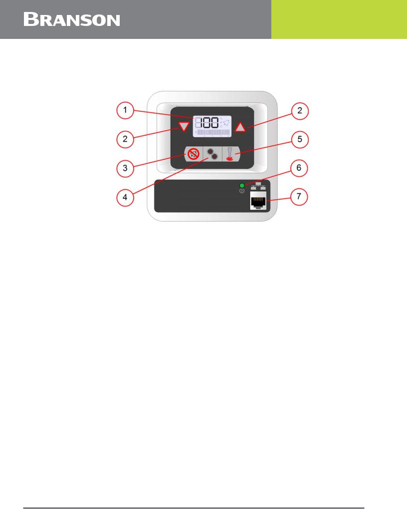
Figure 2.3 DCX S Power Supply Front Panel Controls and Indicators
Table 2.3 DCX S Power Supply Front Panel Controls and Indicators
Item |
Name |
Function |
|
|
|
|
|
1 |
LCD |
For detailed information refer to Figure 2.4 LCD Description |
|
and Figure 2.4 LCD Description. |
|||
|
|
||
|
|
|
|
|
Up/Down |
Use to adjust the amplitude of ultrasonic vibrations (10% to |
|
2 |
100%). Also used to select registers and edit register |
||
Arrow Keys |
|||
|
values. |
||
|
|
||
|
|
|
|
|
Alarm Reset |
Use the Reset key to reset alarms. When changing system |
|
3 |
registers, use the Reset key to set a register back to its |
||
Key |
|||
|
default value. |
||
|
|
||
|
|
|
|
|
Configuration |
Use the Configuration key to change system registers. For |
|
4 |
information on using the Configuration key to set system |
||
Key |
|||
|
registers see 7.4 Configuring the Power Supply Registers. |
||
|
|
||
|
|
|
|
5 |
Ultrasonic Test |
Use the Test key to turn on Sonics. |
|
Key |
|||
|
|
||
|
|
|
|
6 |
Power-On |
Lights when the power supply is connected to main power |
|
indicator |
and the power switch is on. |
||
|
|||
|
|
|
|
|
|
Use the Ethernet Service port to connect to the DCX S Power |
|
|
Ethernet |
Supply Web Page Interface. |
|
7 |
For detailed information on using the web page interface |
||
Service Port |
|||
|
|
refer to the DCX S Power Supply Web Page Interface |
|
|
|
Instruction Manual (100-412-187). |
|
|
|
|
20 |
100-412-183 REV. 13 |
 Loading...