

Page 1

Digital Sonifier
®
Models 250 & 450
User’s Manual
EDP 100-214-239
Rev. A
BRANSON Ultrasonics Corporation
41 Eagle Road
Danbury, Connecticut 06813-1961 U.S.A.
(203) 796-0400
Page 2

EDP 100-214-239 Rev. A February 2001
Manual Change Information
At Branson, we strive to maintain our position as the leader in ultrasonics plastics joining,
cleaning and related technologies by continually improving the designs, circuits and compo-
nents in our equipment. These improvements are incorporated as soon as they are developed
and thoroughly tested.
Information concerning any improvements will be added to the appropriate technical docu-
mentation at its next revision and printing. Therefore, when requesting service assistance for
specific units, note the Release information found on the cover of this document, and refer to
the printing date which appears in the lower right corner of this page.
Patents and Copyright
Copyright ©1998 by Branson Ultrasonics Corporation, Danbury, Connecticut, U.S.A.
All rights reserved.
Manual part number: EDP 100-214-239 Rev. A, printed February 2001.
Branson Ultrasonics Corporation equipment is manufactured under one or more of the fol-
lowing U. S. Patents:
4,249,986; 4,315,181; 4,363,992; 4,551,690; 4,651,043; 4,786,356; 4,973,876; 5,095,188;
5,435,863.
Note: Sonifier® is a registered trademark of Branson Ultrasonics Corporation, Danbury,
Connecticut, U.S.A. Other trademarks and service marks respectfully mentioned herein are
held by their respective owners.
Page 3

Digital Sonifier
®
User’s Manual
Forward
Congratulations on your choice of a Branson Ultrasonics Corporation system!
The Branson Digital Sonifier
®
system is the new e st gene ra ti o n of prod uc t using this soph ist i-
cated technology for a variety of customer applications. This manual should be kept with the
system.
Thank you for ch oo si n g a Branson product !
Introduction to this manual
This manual is arranged into seven structured chapters which will help you find the informa-
tion you may need to know to safely handle, install, set up, program, operate, and/or maintain
this product. Additional information is provided in several Appendix chapters.
In the event you require additional assistance or information, please contact our Product Sup-
port department (see
’How to Contact Branson’
on page 1-5 for information on how to contact
us) or your local Branson representative.
Page 4

100-214-239 Rev. A
For Your Notes
Page 5

100-214-239 Rev. A i-5
Digital Sonifier
Page 6

100-214-239 1-1
Safety Considerations
Digital Sonifier
1 Safety and Support
1.1 Safety Considerations --------------------1-1
1.2 General Precautions ---------------------1-2
1.3 Regulatory Compliance--------------------1-3
1.4 Warranty ---------------------------1-4
1.5 How to Co ntact Branson -------------------1-5
1.1 Safety Considerations
CAUTION
j The following safety considerations should be observed when operating t he
Digital Sonifier®:
• Make s ure that the equipm ent is properly grounded. DO NOT operate if it is not.
• The unit is equi pped with a three-condu ctor cord and three-prong grounding-type plug,
and must be plugged into a three-prong grounding-type wa ll recep tacle. DO NOT under
any circumstances remove the power cord ground pron g.
• DO NOT operate the equipment with the cover removed. High voltage is present within
the eq uipm ent wh en connec ted to plant wiring.
• DO NOT turn on the ultrasonics without the converter and horn attached.
• DO NOT touch the horn or tip when ultrasonics are active. When handling, removing, or
attaching a horn or t ip, be sure that the ON/OFF s witch is set to O FF.Touching the horn
or tip while the unit is on can result in seriou s personal injury.
• DO NOT a llow the horn or microtip to contact lab stands, beakers, or similar objects.
Horn/microtip failure may result.
• DO NOT o perate the equipment at more than 70% amplitude when using a microtip
horn.
• Establish a standard of operation and test equipment periodically.
Page 7

1-2 100-214-239
Safety and Support
1.2 General Precaution s
1.2.1 Intended Use of the System
The 250/450 Digital Sonifiers can be used to disrupt cells, bacteria, spores, or tissue, and are ideal for initiating and accelerating chemical, biochemical, and physical reactions, and for de-gassing liquids. With the Digital Sonifier, you can prepare
an emulsion to 0.01 micron, homogenize immiscible liquids, polymerize some
materials, and depolymerize others.
1.2.2 Safety Measures and Guards
This manual contains operation instructions for the Digital Sonifier cell disruptor
Models 250 and 450. It contains information essential to the proper use and care
of this equipment. The manual contains notes, warnings, and cautions. These are
described as follows:
NOTE
i Provides information that the reader should follo w to prevent inconvenience.
CAUTION
j Advises the user of a hazard that can cause equipment damage or personal
injury.
WARNING
j Alerts the reader to a hazard that can result in severe personal injury.
Do NOT disregard a WARNING.
1.2.3 Safe Operation
Setup and Operation instructions are found in Chapter 6 of this manual.
For safe operation, please ensure that all people using this equipment follow those
instructions and observe all CAUTION and WARNING notices.
1. Make s ure th at the equipment is properly grounded. DO NOT operate if it is not.
Page 8

100-214-239 1-3
General Precau tion s
Digital Sonifier
2. The unit is equipped with a three-conductor cord and three-prong grounding type
plug and must be pl ugged into a three-prong grounded receptacle. DO NOT under
any circumstances remove the power cord ground prong, or use a plug ‘Adapte r’.
3. DO NOToperateequipmentwiththecoverremoved. Highvoltage is present within
the equipment when connected to plant wi ring.
4. Do not al low the horn or microtip to contact lab stands, beakers, etc. or horn/
microtip failure may result.
5. Establish a standard of operation and periodically t es t the equipment , as described
in Ultrasonic Test on page 4-17.
Although the Digital Sonifier operates outside the normalrange of human hearing,
some applications can create audible noise above 85dB. Noise can occur, for
example, when the device touches a solid material, or when its operation causes
nearby objects in the lab to vibrate. If an uncomfortable level of noise is present,
the operator should wear ear protection for safe operation.
Appropriate eye protection should be worn when operating the Digital Sonifier, to
prevent possible splash injury originating in the solution.
WARNING
j
Never touch the horn or tip when ultrasonics are active. Touching the horn or
tip while the unit is on can result in serious injury. When you handle, remove,
or attach a horn or tip, always make sure that the ON/OFF switch is OFF.
1.2.4 Setting Up the Workplace
The unit should be positioned away from radiators and heating vents. A fan inside
theunit maintains a safe operating temperature in the power supplyby circulating
air over the components. Therefore, place the unit so that the air intake on the bottom of the power supply is not blocked. Periodically, unplug the unit and clean the
air intake underneath the power supply to ensure that dust or dirt is not restricting
the flow of air. If the Digital Sonifier is to be used for remote operation, ensure that
the unit is situated within full view of the operator, to prevent injury or equipment
damage through an accidental or automatic start-up.
1.3 Regulatory Compliance
The Digital Sonifier is designed for compliance withthe following regulatory guidelines.
• European norms EN-61010-1, EN55011, EN50082-1, ENV50140, ENV50141
• IEC 529 (IP-65 water resistant for Membrane Keypad)
The Digital Sonifier is CE compliant.
Page 9

1-4 100-214-239
Safety and Support
1.3 Warranty
Refer to the “Terms and Conditions of Sale” found on the back of your Invoice for
information about the product Warranty issued of your Branson products. If you
have any questions, please contact your Branson representative. The product warranty information is summarized below.
WARRANTY
When used in accordance with written instructions and under normal operating
conditions, Branson Ultrasonics Corp. equipment is guaranteed to be free of
defects in MATERIAL and WORKMANSHIP for two (2) years from the date of original delivery by BRANSON or by an authorized representative. Any unit which
proves defective during the stated period will be repaired free of charge or replaced
at the sole discretion of Branson Ultrasonic S.A., 9, ch. Faubourg-de-Cruseilles,
CH-1227 Carouge/Geneva or an authorized repair station as advised by BRANSON,providedthedefectiveunitis returnedproperlypackedw ith alltransportation
charges prepaid. A limited warranty as specified may apply to certain components
of the equipment.
WARRANTY EXCEPTIONS
This warranty shall not apply to equipment subjected to misuse, improper installation, alteration, neglect, accident or improper repair.
This warranty is limited to the original purchaser and is not transferable.
Horns and tips fabricated by Branson for use in equipment described in this manual
are manufactured to exacting parameters. Using altered or modified horns and tips
or horns and tips otherwise unqualified by Branson can produce undue stresses
that may damage the equipment. Equipment failures resulting from using unqualified horns and tips are not covered by the Branson warranty.
Microtips are designed to give maximum mechanical energy output. Since they
operate close to the stress limits of titanium, Branson cannot guarantee microtips
against failure.
CONTA CT Y O UR B RAN SON RE PRESENTATIVE OR BRANSON ULTRASONICS CORPORATION, DANBURY, CONNECTICUT, SHOULD Y OU HAVE ANY
QUESTIONS CONCERNING HORN QUALIFICATION.
Page 10

100-214-239 1-5
How to Contact Branson
Digital Sonifier
1.4 How to Contact Branson
The mailing address and telephone information for Branson is as follows:
Branson Ultrasonic SA
9, chemin Faubourg-de-Cruseilles / P.O. Box 1031
CH-1227 Carouge/Geneva
Phone : +41-22-304 83 58 Fax: +41-22-304 83 59
Tell the operator which product you have and which person or department you
need.If after hours,please leave a voice messagewith your name and return telephone number.
1.4.1 Before Calling Branson for Assistance
This manual provides information for troubleshooting and resolving problems that
couldoccur with the equipment (see Chapter 7). If you still require assistance,
Branson Product Support is here to help you. The following questionnaire lists the
common questions you will b e asked when you conta ct the Product Support
department, to help identify the problem.
Before c alling, determine the following information:
1. Your company name and location .
2. Your return telephone number.
3. Have your manual with you. If troubleshooting a problem, refer to Chapter 7.
4. Know your equipment model and serial num bers (found on a gray data label on the
units). Information about the Horn (part number, gain, etc.) or other toolin g may be etched
into the tooling. Software- or-firmware based systems may provide a BOS or software versionnumber,w hich may be required. (The Digital Sonifierprovides the firmware information
on the start-up screen.)
5. What tooling (horn) and booster are being used?
6. What are the setup parameters and mode?
7. Is your equipment in an automated system? If so, what i s supplying the “start” signal?
8. Describe the problem; provide as much detail as possible. For example, is the problem
intermittent? H ow o ften does it occur? How long before it occurs if you are just powering
up? If an error is occurring, which error (give error number or name)?
9. List the steps you have already taken.
10. What is your application, including the material s being processed?
11. Have a list of service or spare parts you have on hand (tips, horns, etc.)
Page 11

1-6 100-214-239
Safety and Support
Returning Equipment for Repair
Before sending equipment for repair, provide as much information with the equipment to help determine the problem with the system. Fill in any details below or on
a separate sheet.
1. Describe the problem; provide as much detail as possible. For example, is this a
new problem? Is the problem intermittent? How often does it occur? H ow long
before it occurs if you are just powering up?
________________________________________________________________
________________________________________________________________
________________________________________________________________
2. Is y our equipm ent i n an automat ed s ystem? If so, is the problem related to Start/
Stop control, or interaction with P LC’s or other devices, etc.?
3. If the problem is with an external signal or output, which one?
If known, include plug/pin # (e.g., P29, pin #3):
__________________________________
4. What are the setu p parameters?
________________________________________________________________
________________________________________________________________
5. What is your application (e.g., cont inuous, pulse, temperature, etc.)?
________________________________________________________________
6. Name and phone number of the person most familiar with the problem:
________________________________________________________________
7. Notify th e Branson office prior to shipping the equipment.
NOTE
i ToReturn Equipment to Branson, you must firstobtain an RGA number from
a Branson representative, or the shipment may b e delayed or refused.
8. For equipment not cov ered by warranty, include a purchase order for the repair
costs to avoid delay.
9. Pack carefully in original packing mate rial to avoid damage in shipment.
10. Return general repairs by any desired method. Send priority repairs by air freight.
11. Prepay the transportation charges FOB Danbury, Connec ticut, U.S.A.
Notes:
________________________________________________________________
________________________________________________________________
________________________________________________________________
Page 12

100-214-239 1-7
How to Contact Branson
Digital Sonifier
Returning Equipment for Repair (to Geneva facility)
NOTE
i To return equipment to Branson, you must first obtain an RGA number from
a Branson representative, or the shipment may b e delayed or refused.
If you are returning equipment to Branson for repair,you must first call the Danbury
Repair department to obtain a Returned Goods Authorization
(RGA)number.(If
you request it, the repair department will fax a Returned Goods Authorization form
to fill out and return with your equipment.)
Branson Ultrasonic SA
9, chemin Faubourg-de-Cruseilles / P.O. Box 1031
CH-1227 Carouge/Geneva
Phone : +41-22-304 83 58 Fax: +41-22-304 83 59
• Provide as much information as possible that wil l help identify the need for repair.
• Carefully pack the equipment in original packing cartons.
• Clearly label all shipping cartons w ith the RGA number on the outside of cartons as well
as on your packing slip, along with the reason for return.
• Return general repairs by any convenient method. Send prio rity repairs by air freight.
• You must prepay the transportation charges FOB Danbury, Connecticut, U.S.A.
Obtaining Replacement Parts
You can reach Branson Parts Store at the following telephone numbers:
Branson Part Store
direct telephone number: +41-22-304 83 58
fax number: +41-22-304 83 59
Many parts can be shipped the same day if ordered before 2:30 p.m., Eastern time.
A parts list is found in Section 7 of this manual, listing descriptions and EDP part
numbers. If you need replacement parts,coordinate the following with your purchasing agent:
• Purchase order number
• ‘Ship t o’ information
• ‘Bill to’ information
• Shipping instructions (air fr eight, truck, etc.)
• Any special i ns truct ions (for examp le, “Hold at the airport and call”). Be sure to give a
name and phone number
• Contact name information
Page 13

1-8 100-214-239
Safety and Support
For Your Notes
Page 14

100-214-239 Rev. A 2-1
Overview o f Digital Sonifier
Digital Sonifier
2 Introduction to the Digital Sonifier
2.1 Overview of Digital S onifier------------------2-1
2.2 Controls and Commands -------------------2-3
2.3 System Features -----------------------2-9
2.1 Overview of Digital Sonifier
The 250/450 Digital Sonifier is often used by laboratory personnel in the medical and chemical
process fields. The system consists of three core elements: the power supply, the controls, and
the converter and horn. The system can interface with customer equipment including a remote
computer or terminal, dot matrix printer, temperature probe, and User I/O.
Figure 2.1 Digital Sonifier
Power Switch
Amplitude Control
Front
Panel
Keypad
Bargraph
LCD Display
Select keys
and
Arrow keys
Page 15

2-2 100-214-239 Rev. A
Introduction to the Digital Sonifier
The 250 and 450 Digital Sonifiers differ only in their output power ratings, measured when the
output control is at maximum setting. The 250’s maximum available output power is up to 200
watts; the 450’s maximum available output power is up to 400 watts.
The digital controls on the Digital Sonifier allow for accuracy and repeatability of control set-
tings. You enter application parameters into the system either through the keypad on the front
panel of the unit, or remotely through a computer keyboard, and can save up to twenty (20)
sets of preset control parameters. You can view operating parameters through the twenty-char-
acter, four-line LCD display on the unit control panel and on a remote terminal if one is con-
nected. At System Setup, you can select a language for the display: English, German, French,
Italian, or Spanish.
The Digital Sonifier’s power supply converts AC line voltage to 20kHz electrical energy. This
high-frequency electrical energy is fed to a converter where it is converted to mechanical vibra-
tions. The heart of the converter is a lead zirconate titanate electrostrictive element which,
when subjected to an alternating voltage, expands and contracts. The converter vibrates in a
longitudinal direction and transmits this motion to the horn tip immersed in the solution,
which causes cavitation. The implosion of microscopic cavities in the solution results, causing
the molecules in the medium to become intensely agitated. The ultrasonic vibrations transmit-
ted through the horn can also be applied directly to a solid workpiece, such as tissue, through
a variety of different tips that can be attached to the horn.
The Digital Sonifier is a constant amplitude device. As the load or pressure on the horn face
increases, the power supply develops more power to maintain the amplitude for any given out-
put control setting. When the horn is operated in air, it is subjected to minimum pressure, and
minimum power is required to maintain amplitude.
The load increases when the horn is immersed in a liquid; the more viscous the liquid, the
higher the load and the more power developed. If a flow-through cell that can be pressurized
is used, thereby increasing pressure on the horn, even more power is developed. For any given
application, more power results when a horn of higher amplitude or larger radiating surface is
used, or when any horn is driven at higher amplitude by increasing the amplitude.
By setting various operation parameters, you can precisely control the way in which ultrasonics
are applied to the sample. You can:
• Specify the time duration of the experiment
• Adjust the amplitude setting between 10% and 100% of maximum amplitude
(microtip 70% maximum)
• Prevent excessive temperature increase in the sample by setting ultrasonics to
operate in Pulse m ode or in Pulse/Pause mode
• Bring a sample to a desired temperature an d hold it there, v ary ing by only a few
degrees, for a d es ired duration using the Pulse/Paus e mode
• Set the maximum allowable temperature in t he sample, so that ultrasonics will
stop automatically when the specified temperature is reac hed
Page 16

100-214-239 Rev. A 2-3
Controls and Commands
Digital Sonifier
2.2 Controls and Commands
This section describes the controls and commands that you use to operate the Digital Sonifier.
A detailed description of how and when to use each front panel control, the valid formats for
the data that you enter, and the response you receive from the system when you use each of
these controls is provided in
Chapter 6, Operations
.
The Digital Sonifier is equipped with a keypad and LCD display on the front panel of the unit.
With the keypad, you can set functional modes of operation and input digital parameters. Avail-
ability of the various functions depends on the mode or state of the system. If you attempt to
use a function that is not available, you will be alerted by a beep.
Figure 2.2 Digital Sonifier front-panel Controls
MODEL 450 SONIFIER
COPYRIGHT 1997
Digital Sonifier
®
Page 17

2-4 100-214-239 Rev. A
Introduction to the Digital Sonifier
Operation of the Digital Sonifier can also be controlled through a remote computer terminal or User I/O
device. You always have the ability to halt operation, whether control is direct or remote.
Each key on the front panel of the unit, except for the numeric keys, Print and Test, has an LED indicator near
it. When the key is active, the LED is turned on. Some of the keys on the Digital Sonifier keypad have equivalent
commands (preceded by !) that can be entered through the remote terminal’s keyboard.
• Section 2.2.1, Digital S onifier Keypad Description, beg inning on page 2-4, describes each key on the
Digital Sonifier keypad and identifies its equivalent remote terminal command (preceded by an ! exclamation point) if applicable.
• Section 2.2.2, R emote Terminal Commands, beginning on page 2-7, provides a detailed desc ript ion of
all remote terminal commands. S ec ti on 2.2.3, Back Panel Connect ions, on page 2-8, d es cribes the back
panel of the unit.
2.2.1 Digital Sonifier Keypad Description
LCD Display
The front panel is equipped with a four-line, 20-character display screen where menus, parameter options, mes-
sages, and warnings are displayed. If the data being displayed has more than one page, you can navigate up and
down in the display by pressing the Page Up and Page Down arrow keys.
The f irst page of a typical Ready display.
If you wish to see the second page, press
the Down Arrow button.
The s ec ond page of a Ready display.
If y ou w ish t o see the first page, press the
Up A rrow button.
PRESET ID#16
TIME= 0:12:52 hr/m/s
MAX. TEMP= 104.3
°F
AMPLITUDE= 43 %
PULSE ON= 2.1 SEC
PULSE OFF= 1.6 SEC
PULSE TEMP= ___._ F
PROBE TEMP= 67.6
°C
Page 18

100-214-239 Rev. A 2-5
Controls and Commands
Digital Sonifier
Line Select Keys
There are four Line Select keys to the right of the display. When a Line Select key is active, the
LED next to it is turned on. You can press a Line Select key to:
• Select a line in the Parameter Entry menu display for a parameter entry.
• Toggle values in a parameter or System Set up sub menus (for exam ple, Yes or
No).
• Select an item from the options available when the system issues a warning/
error mes s age.
Once a Line Select key is pressed, its LED is turned off. When you begin entering a value for
a parameter you selected with a Line Select key, all the other Line Select keys become inactive
and their LEDs are also turned off until you complete the parameter entry. If you have selected
a line but have not begun to enter a value, the other Line Select keys remain active, and you can
select another line on which to enter a parameter value.
Page Up and Page Down Keys
The Page Up and Page Down arrow keys are active when you are displaying a menu that has
more than one page. You can use the Page Up and Page Down keys to move up and down in
the menu. If there are more menu items above the page you are viewing, the Page Up arrow is
active and its LED is turned on. If there are menu items below the page you are viewing, the
Page Down arrow is active and its LED is turned on.
Start/Stop Key (!ON and !OFF Commands)
The Start/Stop key and !ON command are active during Parameter Entry mode (except when
you are changing a parameter value) and during the Sonics Active displays. When you press the
Start/Stop key or type in the !ON Command, the experiment is executed, and the LED next
to the key is turned on. When you press the Start/Stop key again or type in the !OFF com-
mand, the experiment is stopped, and the LED is turned off.
Setup Key
The Setup key is active during Parameter Entry mode (except while you are changing a param-
eter value) and while you are viewing the Setup Menu. When you press the Setup key, the first
page of the Setup menu is displayed and the Setup key’s LED is turned on. When you press
the Setup key again, the Setup menu is closed and its LED is turned off.
Test Key (!TS Command)
The Test key and the !TS command are active when the system is in the Ready state. When you
press the Test key or type in the !TS command, ultrasonics are enabled for two seconds. To
turn on ultrasonics for another two seconds, you can press the Test key or type in the !TS com-
mand again.
Page 19

2-6 100-214-239 Rev. A
Introduction to the Digital Sonifier
Pause Key (!H Command)
The Pause key and the !H command are active only when the unit is operating. When you press
the Pause key or type in the !H command, operation of the unit halts and the Pause key’s LED
is turned on. When you press the Pause key or type in the !H command again, the unit resumes
operation, and the LED is turned off.
Recall Key (!R Command)
The Recall key and the !R command are active only during Parameter Entry mode, except when
you are changing a parameter value. When you press the Recall key or type in the !R command,
a message is displayed and the LED is turned on. Refer to
Section 6.6, Save and Recall Presets,
on
page 6-40, for information on how to save and recall presets.
Save Key (!SV Command)
The Save key and the !SV command are active during Parameter Entry mode, except when you
are changing a parameter value. When you press the Save key or type in the !SV command, a
message is displayed and the LED is turned on. Refer to Section
Section 6.6, Save and Recall Pre-
sets,
on page 6-40, for information on how to save and recall presets.
Print/Send Key (!P and !S Commands)
The Print/Send key and the !P and !S commands are only active after a test or experiment has
been executed, and before another test or experiment begins or the Setup menu parameters are
changed. For this function to operate, a printer, a remote terminal, or both must be enabled.
When you press the Print/Send key, report data is sent to the remote terminal and to the
printer. Refer to
Section 6.7, Printing/Sending Reports,
on page 6-41, for a description of the data
that is sent to the terminal and printer.
Enter Key
You can press the Enter key on the Digital Sonifier or on the computer keyboard to:
• Cause the system to accept a modified parameter value
• Clear an error/warning message.
• Store a Setup parameter value
If you have entered a modified parameter value, the system checks the value for validity and
format. If the v alue you entered is valid, the value is accepted, and it replaces the old value. The
original value is lost and cannot be recovered unless it has been stored under a preset ID num-
ber. If the modified value is invalid, an appropriate error message is displayed.
Page 20

100-214-239 Rev. A 2-7
Controls and Commands
Digital Sonifier
Clear Key
The Clear key on the Digital Sonifier is active at any time when a parameter can be changed.
If you press the Clear key when you are modifying a parameter value, the entry field becomes
blank, and the cursor is moved to the least significant position. If you press the Enter key while
the entry field is blank, no value is stored for the parameter.
Numeric Keys
The keys for 1 through 9 and 0 are active at any time when a parameter has been selected to
be changed.
2.2.2 Remote Terminal Commands
This table describes the remote terminal commands and their functions. All of the remote ter-
minal commands must be preceded by an exclamation point. Refer to
Chapter 6, Operations
, for
a description of the system’s response to each of these commands and the actions you should
take at each response.
Ta ble 2-1: Remote Terminal Commands
Send this
command...
When you want to...
!T Enter the TIME duration val ue.
!MT Enter th e MAX IMUM T EMPERATURE value.
!PO Enter the PULS E O N time value.
!POF Enter the P U LSE OFF time value.
!PPT Enter the Pulse Temperature value.
!S Send all report data to the remote terminal.
!P Print all report data, if a printer is enable d.
!R Recall a particular preset.
!H
Pause operation of the Digital Sonifier until you send another !H
command.
!MT Enter the M ax im um Temperature value.
!TS Test the system for two seconds.
!ON Start the experiment.
!OFF Stop the experiment.
!KL
Lock out the keypad on the front panel. The keypad is enabled
again if you send another !KL command, or if you turn the power off
on the Dig ital Sonifier and then turn it on.
!SV S av e the parameters entered.
!RP View all the test or experiment paramet er values.
Page 21

2-8 100-214-239 Rev. A
Introduction to the Digital Sonifier
2.2.3 Back Panel Connections
Figure 2.3 Back Panel of Digital Sonifier
The back panel of the Digital Sonifier is equipped with:
• An IE C -type power cord connec tion for connecting the power suppl y to a
grounded electrical outlet.
• A fuse holder for access to a replaceable 5x20mm protective fuse. The fuse is
a glass slow-blow type (refer to the data tag for the fuse rating).
• A converter cable with connector to connect the power supply to the Converter.
• An RS-232 connector (female DB9) for connecting a remote comp uter terminal
to the unit. This connection requires a cable w ith a 9-pin male connector.Serial
ASCII data is transferred through this connection at a user-selectable baud rate
of 1200, 2400, 9600, or 19200 bps with 8 databits, 1 stop bit, and no parity.RX,
TX, and Signal Ground are supported.
• A parallel printer connector (female DB25) re quiring a 25-pin male connector.
During System Setup, you can select the dot-matrix printer choices from Panasonic, E pson, or IBM .
• A User I/O connector (female DB15) requires a cable with a 15-pin male DB15
connector. The User I/O provides proprietary system control signals
• A 1/4-inch phone-jack s t yle con nec tor for an optional temperature probe.
IEC-type power
cordset connector
Temperature P robe
connector
Remote
Terminal
Parallel
Printer
User I/O
connector
Fan
Fuse holder
Converter cable
and connector
(RS-232)
Page 22

100-214-239 Rev. A 2-9
System F eatures
Digital Sonifier
2.3 System Features
The Digital Sonifier includes the following features:
• Front-panel system O n/O ff switch
• Separate fron t-panel Stop and Paus e buttons f or experiment c ycle s
• Power output of up to 200 watts (Model 250) an d up to 400 watts (Model 450)
• Nominal 117 Volt ( North American) and 200-245 Volt (export) models available (factory
set)
• Multiple languages for display messages: English, Spanish, Italian, German or French.
• Front-panel LCD display, showing parameter sett ings, alarms and messages
• Membrane front panel with num eric keypad for parameter entry and function selection
• Digital parameter setting, with valid parameter range checking
• Twenty (20) presets for different parameter Setups
• Digital Wattmeter
• Front panel Bargrap h display of relative power while running
• Amplitude control, analog, adjustable while running
• Pulse or Continuous operation
• Temperatu re option
• Sample Hold using Pulse/Pause operation
• Digital Timer (9 hours, 59 minutes, 59 seconds)
• Automatic end-of-cycle using Limits
• Factory-tuned 20 kHz u ltrason ic design, requires no user adjustment
• Parallel Printer interface
• Printed Report capability, with date stamp and parameter information
• Serial interfa ce (for remote computer or terminal)
• User I/O, offers remote start/stop control
For additional feature information, please contact your Branson representative.
Page 23

2-10 100-214-239 R ev. A
Introduction to the Digital Sonifier
For Your Notes
Page 24

100-214-239 Rev. A 3-1
Delivery and Handling
Digital Sonifier
3 Delivery and Handling
3.1 Delivery and Handling
The Digital Sonifier has no special handling constraints. On receipt of your Digital Sonifier sys-
tem, take the following steps:
1. Inspect the carton for signs of damage.
2. Open the carton and locate the packing list.
3. Carefully unpack t he components and check them against the packing list.
4. Save all packing materials in case the equipment needs to be shipped.
5. Inspect the components for any damage that may have oc curred during s hipping.
Report all shipping damage to your carrier.
Page 25

3-2 100-214-239 Rev. A
Delivery and Handling
For Your Notes
Page 26

100-214-239 Rev. A 4-1
Installation Chec klist
Digital Sonifier
4InstallationandSetup
4.1 Installation Checklist ---------------------4-1
4.2 System Block Diagram --------------------4-2
4.3 System Component Description ---------------4-2
4.4 Assembling the Equipment ------------------4-9
4.5 Input Power Requirements ------------------4-13
4.6 Electrical Connections to Equipment-------------4-13
4.7 Guards and SafetyEquipment ----------------4-17
4.8 Ultrasonic Test ------------------------4-18
4.1 Installation Checklist
To install the Digital Sonifier, you will need these items:
• Digital So nif ier unit
• Power cordset
• Converter
• Horn (and horn tips, if applicable)
• Spanner wrench (can be ordered from Branson; refer to Appendix C.)
• Open-ended wrench (can be ordered from Branson; refer to Appendix C.)
• Any acc es s ories shipped with the unit
• Any customer-supplied items, (i.e., c omputer, printer, and temperature probe)
Refer to
Appendix B, Optional Items Parts List
, for specific parts required for the optional items,
and to
Appendix C, Accessories Parts List
, for parts needed for the available accessories.
Page 27

4-2 100-214-239 Rev. A
Installation and Setup
4.2 System Block Diagram
The block diagram shows the relative interaction of the components of a Digital Sonifier sys-
tem. The items inside the bold outline are found in the Digital Sonifier unit. Some elements
shown are optional.
4.3 System Component Description
4.3.1 Standard Components
The standard system components are:
• Sonifier unit
• Power cord
• Converter
• Horn (and tips)
Con-
Ultrasonic Power
Supply Module
Converter
and
Horn
Page 28

100-214-239 Rev. A 4-3
System Component Desc ription
Digital Sonifier
4.3.2 Optional Items
A complete list of optional items is provided in Appendix C of this Guide.
• Printer: Epson FX-compatible dot-matrix printer with a parallel-port interface
with a DB25M cable connector only.
• Remote Terminal or Comput er: Any user-provide d computer o r terminal that
allowsAS C II data to be transferred over an RS-232 serial interface. The pin-out
of the serial connec tor is listed in ’Remote Terminal Connection’ on page 4-14.
The computer interface, s oftware and setup are for the reader to determine.
• Temperat ure Probe: Omega Technologiesmodel #OL-703-PP, 0.125 inches in
diameter and 4.5 inches in length. This item is sold separately by Branson.
Refer to the
Appendix B, Optional Items Parts List
, for information about specific parts needed
for the optional items.
4.3.3 Accessories
Disruptor horns, various horn tips, and a variety of chambers or vessels for batch or continu-
ous processing are available for use with Branson Digital Sonifiers. For a list of Accessories,
refer to
Appendix C, Accessories Parts List
.
Microtips
Particularly useful for processing small volumes, microtips are available in several designs,
tapered and stepped, to meet your application requirements. A Coupling Section may be used
with a microtip horn for certain applications.
Microtips, Coupling Section and Disruptor Horn
Double Step
Tape red Microtip
Coupling
Section
Microtip
Disruptor horn
Note: Do Not
Use with
Disruptor Horn
Page 29

4-4 100-214-239 Rev. A
Installation and Setup
CAUTION
j DO NOT allow the horn or microtip to contact lab stands, beakers, test tubes
or simil ar objects. Microtip failure may result. Breakage of glassware may
result in the loss of a specimen.
Disruptor horns are the base for many microtip applications. Disrupter horns are threaded so
that they may also be inserted into a Flow-Thru chamber attachment (see page 4-6). When
threaded together, a closed chamber is formed between the Tissue Disruptor and the cavity of
the Flow-Thru Attachment. The Tissue Disruptor may also be used alone.
The Tapered Microtip attaches directly to a standard 1/2 inch tapped Disruptor horn. The
amplitu de at the end of a tap ered tip is thr ee and one- hal f times g re ate r tha n tha t of the sta n-
dard horn. The tapered tip is recommended for difficult applications such as spores, fungi,
yeast, muscle, and connective tissue. Excellent results can be achieved on volumes ranging
from 3 to 20 ml in a comparatively short period of time. The diameters of the tapered micro
tips are 1/8 inch (3.2 mm), 3/16 inch (4.8 mm), and 1/4 inch (6.4 mm).
The stepped microtip is a two-piece unit, consis ti ng of a Coupling Section and a lower double-
step tip. Because the coupling section is attached directly to the converter, the standard disrup-
tor horn must be removed prior to using the stepped microtip. Recommended for use on
extremely small volumes, the stepped microtip can be used to treat volumes ranging from 0.5
to 20 ml. Applications for this tip include red and white blood cells, tissue culture cells, HeLa
cells, and the complete range of cells that have low to medium resistance to breakage.
To prevent foaming or aerosoling while processing small quantities with the tapered or stepped
microtips, the us e of a conical-sh ap ed tube s uch as a reaction vial or a cut down centrifuge tube
is recommended.
CAUTION
j When u sing microtips, do not exceed a maximum Amplitude Control setting
of 70%. The microtip will break if driven at higher amplitu des .
Tissue Disruptor
Designed for disintegration of difficult tissues, this stainless steel accessory has a specially con-
structed cell bottom that holds up to six grams of tissue. A water jacket may be provided for
cooling.
Page 30

100-214-239 Rev. A 4-5
System Component Desc ription
Digital Sonifier
Cup Horn
Cup Horns allow materials to be treated in small vials or test tubes without immersing the
ultrasonic horn or micro tip in the material, thereby providing completely sterile conditions. A
Cup Horn is attached directly to the converter, and the assembly is mounted upside-down on
the lab stand with the Cup Horn at the top. With chilled water in the Cup Horn, test tubes are
suspended in the Cup with the contents of the tubes just below the water level. Ultrasonic
energy is then conducted from the surface of the horn, through the water and test tube walls,
to the contents of the tube.
Some energy loss may occur when applying ultrasonics in this indirect way, and processing can
take longer than if the ultrasonic horn were immersed directly in the solution.
There are two types of Cup Horn, a high intensity unit that will accommodate a single test tube,
and a larger unit for multiple test tubes. The high intensity Cup Horn has a concave bottom
that focuses the ultrasonic energy on the bottom of the tube. The larger unit, with a diameter
of two or three inches, allows the immersion of multiple test tubes. The larger Cup Horns have
clear plastic walls, which permit easy viewing of the activity in the tubes during processing.
Both types of Cup Horn are designed to allow chilled water to circulate through the cup to
prevent heating of the solution as a result of the ultrasonic activity.
CAUTION
j The bottom of the t es t tubes should not be in contact with the surface of the
ultrasonic horn. Such contact c ould caus e break age and loss of samp le.
Cup Horn
Inlet / Outlet
Cavity
Page 31
4-6 100-214-239 Rev. A
Installation and Setup
Flow-Thru Horn
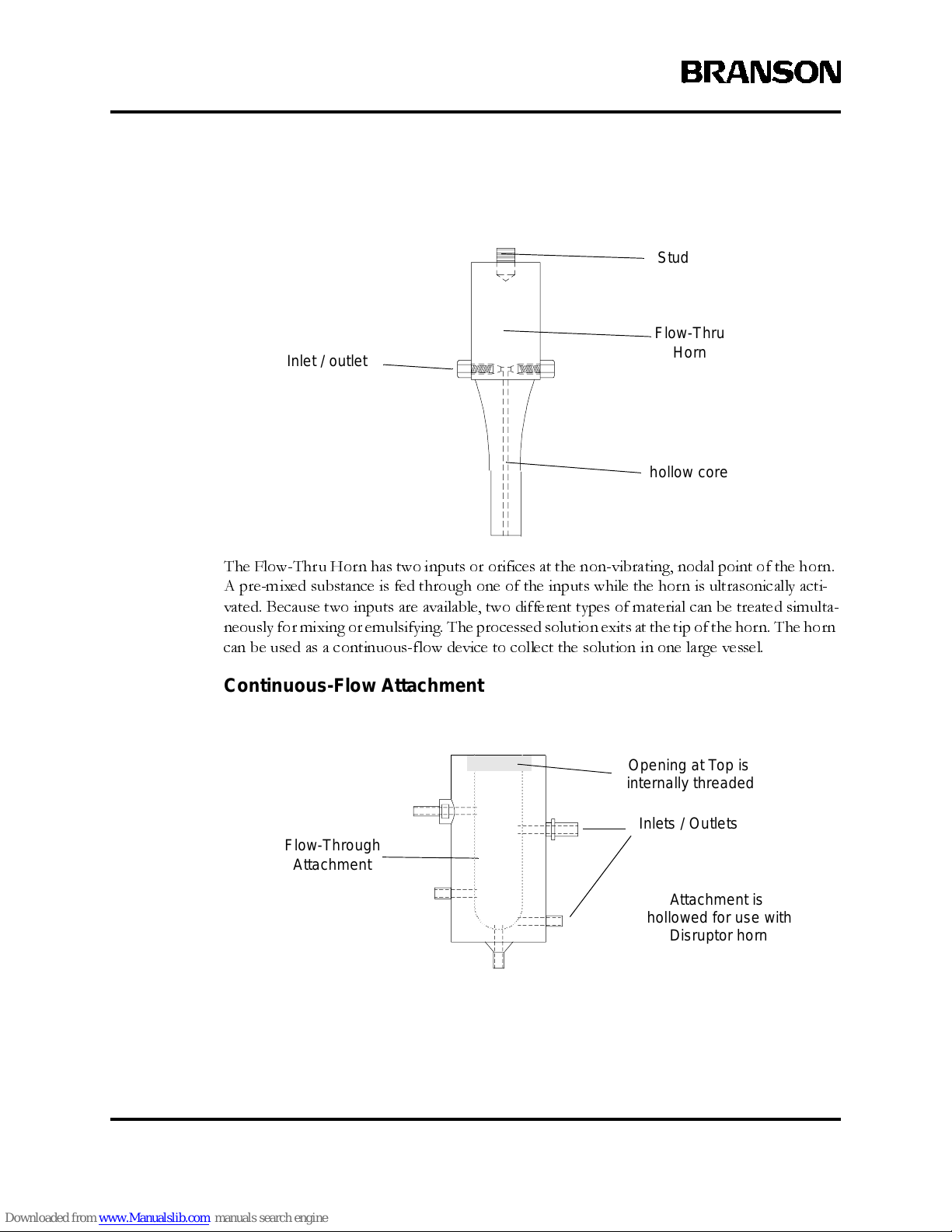
The Flow-Thru Horn has two inputs or orifices at the non-vibrating, nodal point of the horn.
A pre-mixed substance is fed through one of the inputs while the horn is ultrasonically acti-
vated. Because two inputs are available, two different types of material can be treated simulta-
neously for mixing or emulsifying. The processed solution exits at the tip of the horn. The horn
can be used as a continuous-flow device to collect the solution in one large vessel.
Continuous-Flow Attachment
Flow-Thru
Horn
Inlet / outlet
hollow core
Stud
Inlets / Outlets
Flow-Through
Attachment
Opening at Top is
internally threaded
Attachment is
hollowed for us e wit h
Disruptor horn
Page 32
100-214-239 Rev. A 4-7
System Component Desc ription
Digital Sonifier
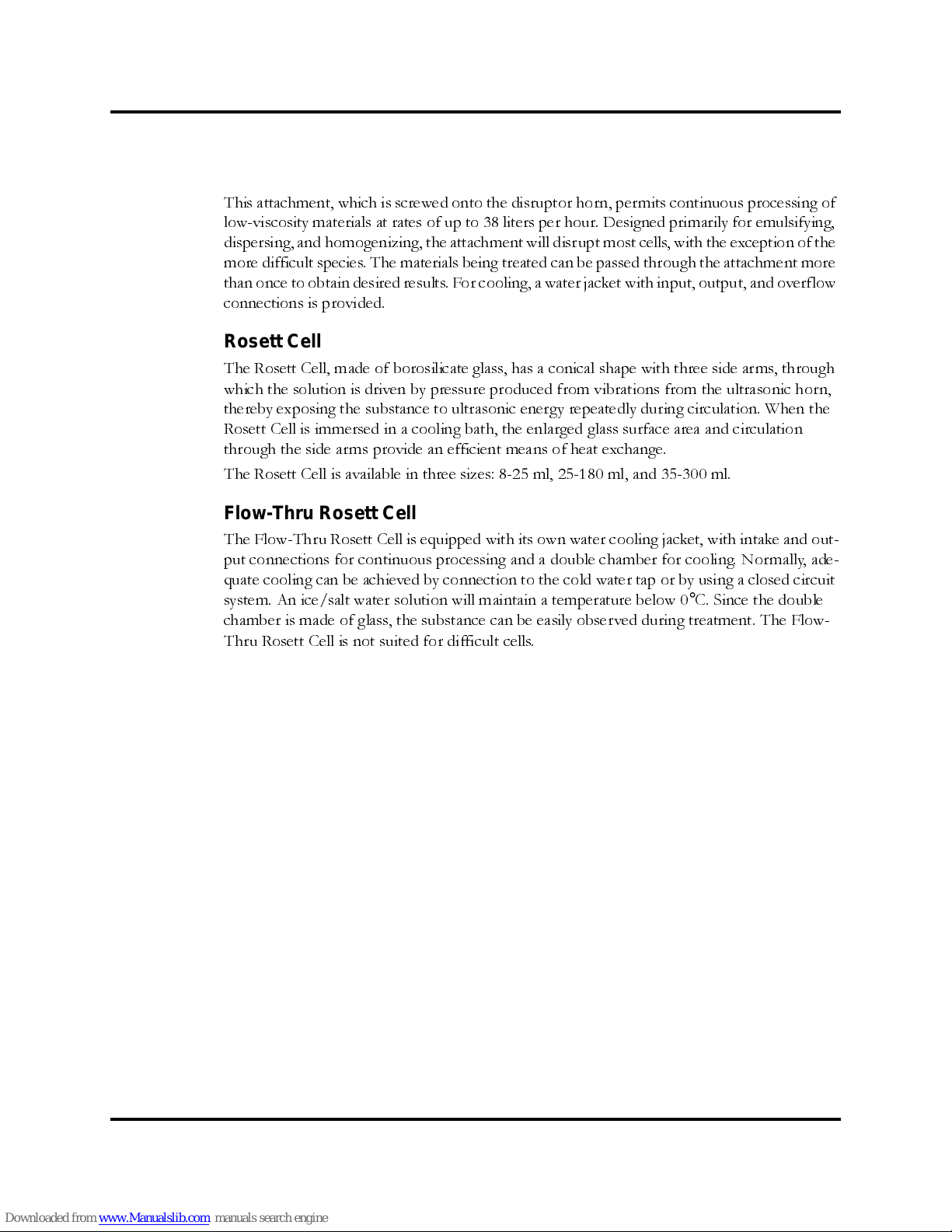
This attachment, which is screwed onto the disruptor horn, permits continuous processing of
low-viscosity materials at rates of up to 38 liters per hour. Designed primarily for emulsifying,
dispersing, and homogenizing, the attachment will disrupt most cells, with the exception of the
more difficult species. The materials being treated can be passed through the attachment more
than once to obtain desired results. For cooling, a water jacket with input, output, and overflow
connections is provided.
Rosett Cell
The Rosett Cell, made of borosilicate glass, has a conical shape with three side arms, through
which the solution is driven by pressure produced from vibrations from the ultrasonic horn,
thereby exposing the substance to ultrasonic energy repeatedly during circulation. When the
Rosett Cell is immersed in a cooling bath, the enlarged glass surface area and circulation
through the side arms provide an efficient means of heat exchange.
The Rosett Cell is available in three sizes: 8-25 ml, 25-180 ml, and 35-300 ml.
Flow-Thru Rosett Cell
The Flow-Thru Rosett Cell is equipped with its own water cooling jacket, with intake and out-
put connections for continuous processing and a double chamber for cooling. Normally, ade-
quate cooling can be achieved by connection to the cold water tap or by using a closed circuit
system. An ice/salt water solution will maintain a temperature below 0
°
C. Since the double
chamber is made of glass, the substance can be easily observed during treatment. The Flow-
Thru Rosett Cell is not suited for difficult cells.
Page 33
4-8 100-214-239 Rev. A
Installation and Setup
Soundproof Enclosure
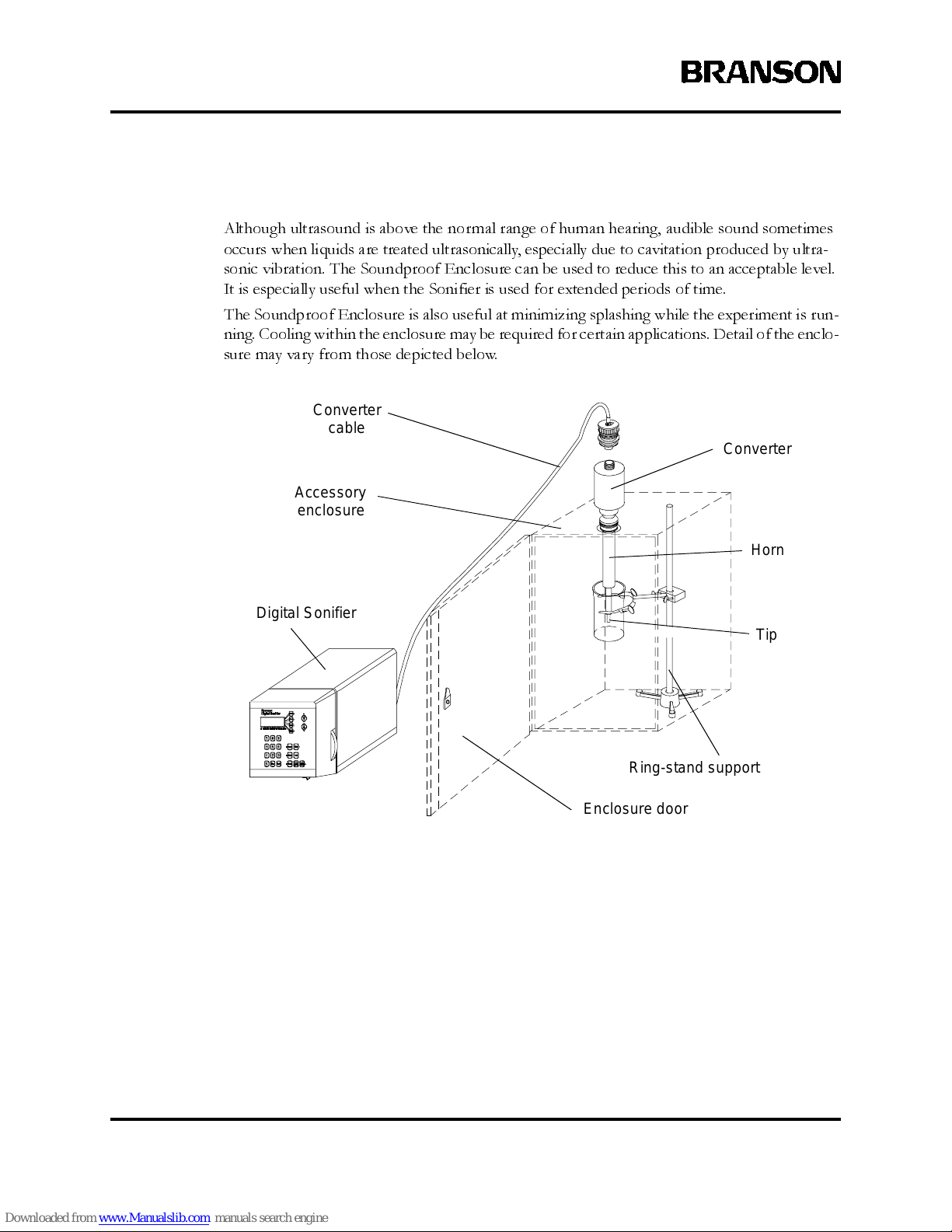
Although ultrasound is above the normal range of human hearing, audible sound sometimes
occurs when liquids are treated ultrasonically, especially due to cavitation produced by ultra-
sonic vibration. The Soundproof Enclosure can be used to reduce this to an acceptable level.
It is especially useful when the Sonifier is used for extended periods of time.
The Soundproof Enclosure is also useful at minimizing splashing while the experiment is run-
ning. Cooling within the enclosure may be required for certain applications. Detail of the enclo-
sure may vary from those depicted below.
Converter
Horn
Tip
Accessory
enclosure
Converter
cable
Enclosure door
Ring-stand support
Digital Sonifier
Page 34

100-214-239 Rev. A 4-9
Assembling the Equipment
Digital Sonifier
4.4 Assembling the Equipment
The Digital Sonifier unit is pre-assembled and requires no special tools, however other com-
ponents must be connected to the unit in order for the system to operate. Some assembly of
the ultrasonic horn is required, as described in the following sections.
4.4.1 Setup Procedure
To set up your Digital Sonifier for an experiment, take the following steps:
To remove a horn, use spanner wrenches shipped with the system. Never attempt to remove
a horn by holding the converter housing in a vise. If necessary, secure the largest portion of
the horn in a soft-jawed
vise. See
Section 4.4.2, Connecting Tips, Horns, and Converters
, on p age 4-10.
Step Action
1
Connect t he tip, horn, and converter, following the procedu re in Section
4.4.2, Connecting Tips, Horns, and Converters, on page 4-10.
2
Mount the converter/horn assembly in a laboratory stand or other suitable
support. Secure the c lam p on the converter housing.
3
Set the O N /O FF swit c h on the front of the unit to the O (OFF) position
4
Plug the line cord into the unit, and then into an appropriate electrical
power outlet, ens uring that the power supply is grounded to prevent electrical shock .
Page 35
4-10 100-214-239 R ev. A
Installation and Setup
4.4.2 Connecting Tips, Horns, and Converters
Connecting the Horn to the Converter
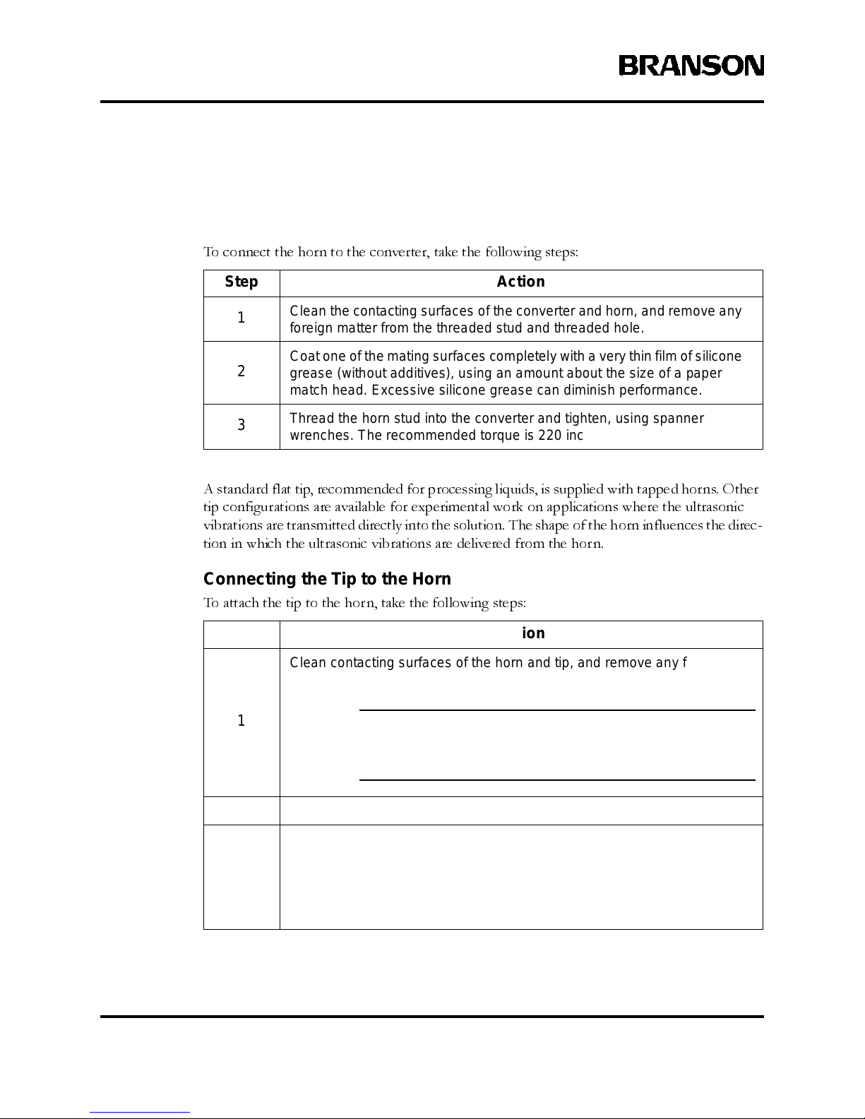
To connect the horn to the converter, take the following steps:
A standard flat tip, recommended for processing liquids, is supplied with tapped horns. Other
tip configurations are available for experimental work on applications where the ultrasonic
vibrations are transmitted directly into the solution. The shape of the horn influences the direc-
tion in which the ultrasonic vibrations are delivered from the horn.
Connecting the Tip to the Horn
To attach the tip to the horn, take the following steps:
Step Action
1
Clean the c onta cting surfaces of the converter and horn, and remove any
foreign matter f rom the threa ded stud and threaded hole.
2
Coat one of the mating surfaces completely with a very thin film of silicone
grease (without additives), using an amou nt about the size of a paper
match head. Excessive silicone grease can diminish performance.
3
Thread t he horn stud into the converter and tighten, using spanner
wrenches. The recommended torque is 220 inch-pounds (24.85 Nm).
Step Action
1
Clean contacting surfa ce s of the horn and tip, and remove any foreign
matter fr om the threa ded stud and threaded hole.
CAUTION
j The t ip must be installed clean and dry, or the po wer supp ly
may not tune and operate correctly.
2
Hand-assemble the t ip to the horn.
3
Using a spanner wrench on the horn and an open-end wrench on the tip,
tighten the tip. See Figure 4.3. Torque s pec if icat ions for the various
threaded tips follow:
1/4-20 — tighten at 90 in ch -lbs./10. 16 Newto n-meters
3/8-24 — tighten at 180 i nc h-lbs./20.33 Newt on-meters
Page 36

100-214-239 Rev. A 4-11
Assembling the Equipment
Digital Sonifier
Tightening a tip on a horn, using spanner wrench and open-end wrench
Converter
Horn
Tip Wrench
Spanner
Tip
Page 37

4-12 100-214-239 R ev. A
Installation and Setup
4.4.3 Horn Amplitudes
Use the following charts to determine the correct system settings for the horns you are using.
Approximate Microtip Amplitudes
Suggested Amplitude Values for various Horns
Horn EDP No. Description
Amplitude Control S ettings
10% 50% 100%
101-147-037
1/2" Diameter Tapped
Stepped Disruptor
21.0*
0.0008"
76.0*
0.0029"
145.0*
0.0057"
101-147-042
1/2" Dia meter Solid
Catenoidal Disruptor
21.0*
0.0008"
76.0*
0.0029"
145.0*
0.0057"
101-147-041
1/2" Dia meter Solid
Exponential Disruptor
10.0*
0.0004"
34.0*
0.0013
65.0*
0.0026”
101-147-039
3/8" Diameter Solid Stepped
Disruptor
36.0*
0.0014"
125.0*
0.0049"
240.0*
0.0094”
101-147-043
3/4” Dia meter Solid Stepped
Disruptor
9.5*
0.0004”
33.0*
0.0013”
63.0*
0.0025”
101-147-035
3/4”Diamet er Solid High Gain
Disruptor
19.0*
0.0007”
68.5*
0.0027”
130.0*
0.0051”
101-147-044
1.0” Dia meter Solid Stepped
Disruptor
6.3*
0.0002”
21.5*
0.0008”
40.5*
0.0016”
* All measurem ents in microns unless otherwise specified
Horn EDP No. Description
Amplitude Control S ettings
10% 40% 70%
101-148-062 1/8” Dia meter Tapered
116.0*
0.0046”
306.0*
0.0122”
494.0*
0.0194”
101-148-069 3/16” Di ameter Tapered
59.5*
0.0023
183.0*
0.0072”
302.0*
0.0119”
101-148-070 1/4” Dia meter Tapered
59.5*
0.0023”
151.0*
0.0059
247.0*
0.0097”
101-063-212 Double Step
64.0*
0.0025”
173.8*
0.0068”
274.0*
0.0108”
* All measurem ents in microns unless otherwise specified
Page 38
100-214-239 Rev. A 4-13
Input Power Requirements
Digital Sonifier
4.5 Input Power Requirements
The input power requirements for the Digital Sonifier are:
• 117 VAC, 50/60 Hz (North American model)
• 200-245 VAC, 50/60 Hz (Export models only)
The Digita l Soni fier is equip ped wit h an IEC-typ e power cord connector. The unit requi res a
single- pha s e, three-w ire, 50/6 0 Hz power sou rce.
WARNING
j To prevent the possibility of electrical shock, always plug the Digital Sonifier
unit into a grounded power source.
The system is fuse-protected with a replaceable glass fuse, 5x20mm, slow-blow type (refer to
the data tag on the system. This fuse should never blow under normal operating conditions.
The fuse holder is found on the rear of the unit, as part of the IEC power connector.
4.6 Electrical Connections to Equipment
All of the connections to the Digital Sonifier are made to the rear of the unit using industry-
standard connectors. Refer to
Section 2.2.3, Back Panel Connections,
on page 2-8 for conn ector
locations. See Appendix B and C for accessory part numbers.
4.6.1 Power Cord
North American units are shipped with a 3-conductor 117 Volt cordset (NEMA 5-15P to IEC
jack). It connects to an IEC-type connector on the rear of the unit. The plug end connects to
your main voltage receptacle, which should be properly fused (depending on your site require-
ments). I t requ ires a conventi ona l NEMA 5- 15 R rece pta cl e for inst al la ti on.
Export units are shipped with a standard Harmonized European cordset (having an IEC-type
jack).
CAUTION
j If you r cordset does not match your main power receptacle, verify that you
have the correct voltage available. Do not connect the system if the voltage
rating of the unit is incorrect for your location, as this c an damage the unit.
Page 39
4-14 100-214-239 R ev. A
Installation and Setup
4.6.2 Remote Terminal Connection
The remote terminal is connected to the rear of the Digital Sonifier through an industry-typical
RS-232 connection. See Back Panel of Digital Sonifier
on page 2-8 for the RS-232 connector
location. The RS-232 connector pin-out is provided below; the connection only supports three
data leads (Ground, RxD and TxD) and does not support handshaking (see
Remote Computer or
Terminal
on page 6-34 for other Setup information). The serial connection requires a straight-
through cable with a 9-pin DB9 male connector with the following leads supported; the remote
end of the cable should match your Remote Terminal device.
The other leads of the RS-232 connector (DB9F) are not supported.
The remote terminal connection should not exceed a 50 foot (15 meters) cable length using
conventional data cabling.
4.6.3 Terminal Connection
A Terminal is a display option that is available through Branson. The terminal is used as a
remote terminal device and connects to the unit as such. In order for the terminal to operate
with the RS-232c serial port of the Digital Sonifier, its configuration options must be set to
match those of the Digital Sonifier’s output.
4.6.4 Printer Connection
The printer is connected to the back panel of the Digital Sonifier (female DB-25 connector)
to a conventional 25- pin para ll el pri nt er cabl e. Your printer cable must have the male DB- 25
connector. Plug the printer cable into the connector and turn the printer on. The Printer must
be Set Up in order to function (see page 6-18).
RS-232 Connector Pin-out
RS-232 Connector Pin
(DB-9F on system)
Pin Designation Common Signal Name
2 RxD Received Data (at unit)
3 TxD Transmitted Data (from unit)
5 Gnd Signal Ground
Page 40
100-214-239 Rev. A 4-15
Electrical Co nnections to Equipment
Digital Sonifier
4.6.5 Temperature Probe Connection
The temperatur e probe is connected to the Digital Sonifier using a 1/4 inch RCA-type phone
jack connector. The Omega Temperature Probe that is specified matches properly, and is the
only temperature device for use with the Digital Sonifier. The Probe temperature is displayed
(example on page 6-32), or the display will shown TEMP OFF if no probe is connected.
4.6.6 User I/O Connection
The Digital Sonifier is equipped with a standard external connection to allow you to design and
connect your own custom interface for controlling the unit. The User I/O interface can be use-
ful when you need to activate the Sonifier remotely, for example, when the operator must start
and stop the unit from another room for safety reasons.
User I/O Pin-Out (DB15F) provide d for customer-designed interface
DB15F Pin Function Signal or Use
1
+5 VDC Source
+5 VDC source (ref. pin 6) when
front-panel Power Switch is On
2
Signal Ground (for Amplitude) Signal Ground
3
Signal Ground (for Power) Signal Ground
4
Signal Ground (for Temperature) Signal Ground
5
Amplitude Signal Output 0-10VDC = 0-100% Amplitude
6
+5 VDC Return +5 VDC G r ound
7
not used no connection
8
not used no connection
9
Start/Stop Control
Apply +5VDC (from pi n 1) to
Start, open circuit to Stop
10 Temperature Limit
+5VDC signal drops to 0VDC
whenthe TemperatureLimit is
reached
11 Test or Running
+5VDC signal drops to 0VDC
when Running
12 Power Signal Output 0-10VDC = 0-100% Power Out
13
Temperatu re Signa l Output
0-10VDC = 0-100 degrees C or
32-212 degrees F
14
Signal Ground Reference Signal Ground
15
not used no connection
Page 41
4-16 100-214-239 R ev. A
Installation and Setup
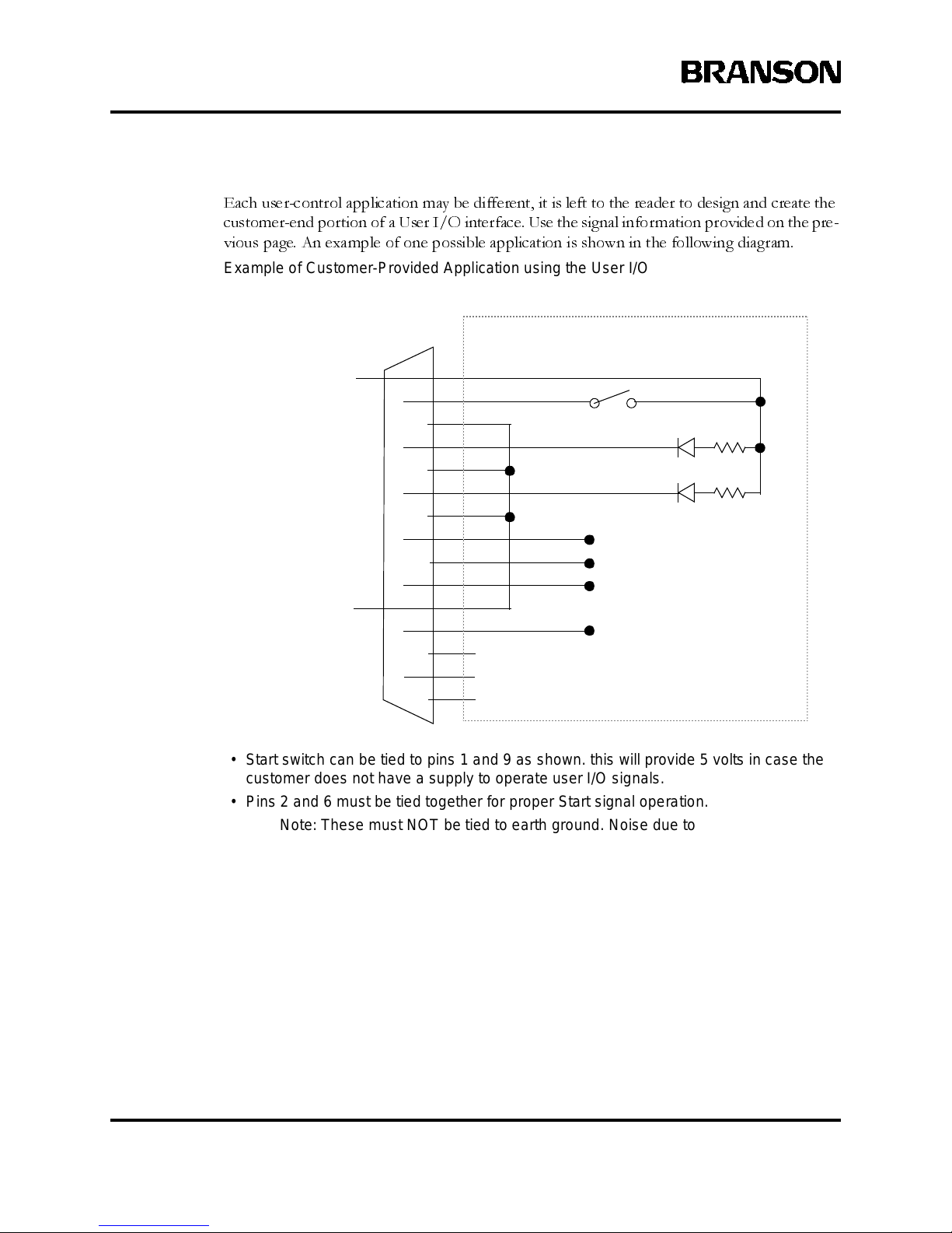
Each user-control application may be different, it is left to the reader to design and create the
customer-end portion of a User I/O int erfac e. Use th e signal informa tio n provided on the pre-
vious page. An example of one possible application is shown in the following diagram.
Example of Customer-Provided Application using the User I/O
• Start switch can be tied to pins 1 and 9 as shown. this will provide 5 volts in case the
customer does not have a supply to operate user I/O signals.
• Pins 2 and 6 mus t be tied together for proper Start signal operation.
Note: These m us t NOT be tied to earth ground. Noise due to groun d loops could
be injected ont o the signals . This will cause improper operation, but will not
damage the unit.
• Pins 3 and 4 must be tied to pin 6 for operation of t he Temperature Limit and Test Running LE D’s respectively, as shown.
• Power, Amplitude and Tem perat ure must be re ferenced to pin 14 for proper signal
measurement.
9
10
11
12
13
14
15
1
2
3
4
5
6
7
8
nc
nc
nc
+5VDC
+5VDC GND
500
500
Power Signal (0-10V)
Amplitude Signal (0-10V)
Temperature S ignal (0-10V)
Ground Reference
Temperature Limit
Test Running
LED
LED
User-Provided Inte rface to User I/O
User I/O (DB15F) on
Digital Sonifier
Start Switch
for Signals
Page 42
100-214-239 Rev. A 4-17
Guards and Safety Equipment
Digital Sonifier
4.7 Guards and Safety Equipment
Although the Digital Sonifier operates outside the normal range of human hearing, some appli-
cations can create audible noise above 85dB. If an uncomfortable level of noise is present, the
operator should wear ear protection for safe operation.
Appropriate eye protection should be worn when operating the Digital Sonifier, to prevent
possible splash injury originating in the solution.
WARNING
j TheUltrasonic Horn can cause injury and/or equipment damage during op er-
ation. To avoid injury or a cci dent, never touch the Ultrasonic Horn while the
System is t urned on, and do not allow the Horn to come in contact with solid
vessels or s upports.
The User I/O may be used to remotely control the System. If this is the case, you must design
in whatever safety precautions are appropriate to your User I/O circuit design to prevent unex-
pected star t- up, which can caus e perso na l inj ury and can caus e equ ipm ent dam ag e.
Page 43
4-18 100-214-239 R ev. A
Installation and Setup
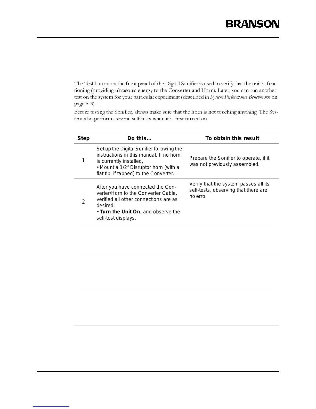
4.8 Ultrasonic Test
The Test button on the front panel of the Digital Sonifier is used to verify that the unit is func-
tioning (providing ultrasonic energy to the Converter and Horn). Later, you can run another
test on the system for your particular experiment (described in
System Performance Benchmark
on
page 5-3).
Before testing the Sonifier, always make sure that the horn is not touching anything. The Sys-
tem also performs several self-tests when it is first turned on.
Step Do this... To obtain this result
1
Setup the DigitalSonifier followingthe
instructions in t his manual. If no horn
is currently installed,
• M ount a 1/2” Disruptor horn (with a
flat tip, if tapped) to the Converter.
Prepare the Sonifi er to operate, if it
was not previously ass embled.
2
After you have conn ec ted the Converter/Horn to the Converter Cable,
verified all other connec tions are as
desired:
• Turn the Unit On, and observe the
self-test displays.
Verify that the system passes all its
self-tests, observing that there are
noerror messages on t he front panel
display.
The Digital Sonifier advances to the
“Ready”mode andshows thenormal
Ready display (see page 2-4).
3
Adjust the Amplitude control to
approximately 50% (observe the
value on the front panel display).
Ensures that ultrasonic energy will
be at some mi d-ra nge value, and will
not cause damage if you were us ing
a microtip (mu st be less than 70%).
4
Verify that the Horn is not touching
anything.
• P ress the Test button on the front
panel. Observe the front panel display.
Verifies the ultrasonic output of the
system. You may hear a soft, highpitchedsound.The bargraph display
will show some o utpu t value. The
test will run for 2 seconds, then stop.
5
If the system sho wed re adings on
the disp lay during the Test,
you may either proceed with your
experiments, or
• Turn the unit off.
Verification that t he Digital Sonifier is
operating and is ready to be set up
for your ex periment.
Page 44
100-214-239 Rev. A 5-1
Technical Specifications
Digital Sonifier
5 Technical Specifications
5.1 Technical Specifications -------------------5-1
5.2 Physical Description ---------------------5-2
5.3 System Performance Benchmark---------------5-3
5.1 Technical Specifications
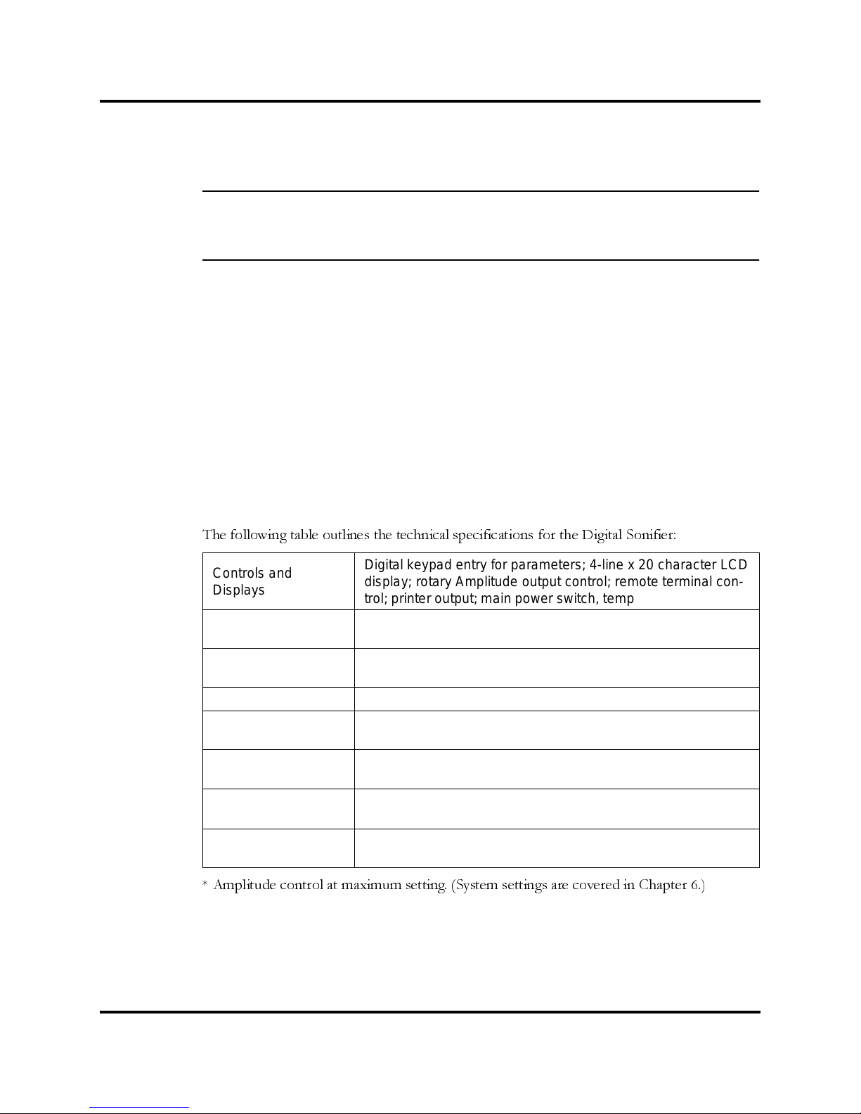
The following table outlines the technical specifications for the Digital Sonifier:
* Amplitude control at maximum setting. (System settings are covered in Chapter 6.)
Controls a nd
Displays
Digital keypad entry for parameters; 4-line x 20 character LCD
display; rotary Amplitude output control; remote terminal control; printer output; main power switch, temperature probe input
Amplitude control
Adjusts amplitude of power s upply output voltage.
Range: 10% – 100% of nominal converter amplitude
Duty Cycle
Intermittent – p ulse duration adjustable
[0.1 seconds – 59.9 seconds] or continuous processing time
Horn Frequency 19.850 – 20.050 kHz
Line Voltage
115V ± 10% @ 50/60 Hz (North American unit)
200-245 ± 10% @ 50/60 Hz (Export only)
Power
250 – up to 200 watts*
450 – up to 400 watts*
Temperature
(ambient)
Operating: 41°F (5°C) to 104°F (40°C).
Storage and shipping: -20°F (-29°C) to 158° F (70° C)
Tuning
Factory set, no tuning necess ary. No user-accessibl e adjustments.
Page 45
5-2 100-214-239 Rev. A
Technical Specifications
5.2 Physical Descriptio n
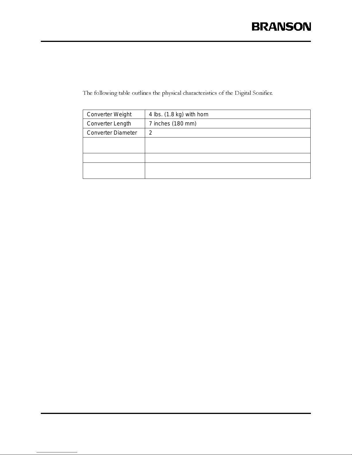
The following table outlines the physical characteristics of the Digital Sonifier.
Converter Weight 4 lbs. (1.8 kg) with horn
Converter Length 7 inches (180 mm)
Converter Diameter 2-1/2 inc hes (60 mm)
Horn Tip Diameter
1/8 i nch – 1.0 inch (3.2 – 25.4 mm), depending on process
needs and Accessory Tip selected
Power Supply Weight 17 lbs. (7.7 kg)
Temperature Probe
Omega Tec hnologies model #OL-703-PP.
It is 0.125 inches in diameter and 4.5 inches long
Page 46

100-214-239 Rev. A 5-3
System Performance Benchmark
Digital Sonifier
5.3 System Perfo rman ce Benchmark
Each application and system configuration is slightly different. System performance will vary
when you change setup parameters and if your horn or tips change, and can affect the results
of your experiments. Creating a benchmark of your initial setup and performance can be useful
at a later date in identifying a change in performance, and can also help in recreating your exact
initial setup.
The following steps are used only to record system performance, not your experiment results.
NOTE
i
Make copies of the following page and keep it on file for future reference.
Use the following steps to create and record a benchmark for your exact setup.
If you are using the Printer option, you may wish to print a report of the results and keep it on
file with the form.
Step Action to Save a Benchmark
1 Make a copy of the Digital Sonifier Setup Form provided on page 5-4.
2
Identify yo ur experiment type on the form, your you own reference.
Set up the Digital Sonifier (be ready to run), and prepare your experim ent.
Turn the Digital Sonifier system On.
2
Set your desired Amplitude control setting (the value is displayed on the bo ttom line of the LCD display) and write the fill in the value on the form.
3
With theHo rn submers ed in your solution, press the Startbutton (located on
the bottom right-hand side of the Sonifier’s keypad). Note any special
immersion comments (depth, how it is supported, etc.)
4
Note the Bargraph reading (the value is displayed on the bottom line of the
LCD display) on the form.
5
Pressthe Down Arrow keyon the keypadand view the POWER reading(the
value is displayed on the bottom line of the LCD display). Record the
POWER reading on the form.
6
Note an y special adjustments, set tings, operating modes, or other system
variables t hat will be helpful at a later time in re-creating your setup. If you
use a Pres et, not e the Prese t ID.
7
Turnthe system off. Record the serial numbers and horn information of the
Digital Sonifier unit, Horn, Converter, and any special equipment. Special
information about t he Horns is etched into the horn.
8 Place the filled-in form in a safe place for future reference.
Page 47

5-4 100-214-239 Rev. A
Technical Specifications
Branson Digital Sonifier Setup Form
Make a copy of this form and use it to record a benchmark for your system’s setup.
Date: Operator:
Experiment/Solution: ________________________________
Digital Sonifier Model: 250 450 117 Volt 200-245 Volt
Unit Serial Number:
__________________________________________________
Converter Serial Number:
__________________________________________________
Horn Type:
__________________________________________________
Parameters, Mode, Preset:
__________________________________________________
__________________________________________________
Amplitude setting (LCD read-out):
__________________________________________________
Bargraph reading:
__________________________________________________
Power Reading: ___________________ watts
Other Setup Notes:
Page 48

100-214-239 Rev. A 6-1
Setup and Operation
Digital Sonifier
6 Operation
6.1 Setup and Operation ---------------------6-2
6.2 Front Panel Controls ---------------------6-5
6.3 Entering System Setup Parameters -------------6-9
System Setup - Language ------------------6-10
SystemSetup-Date --------------------6-12
SystemSetup-TimeofDay-----------------6-14
SystemSetup-TemperatureUnits--------------6-16
SystemSetup-Printer--------------------6-18
SystemSetup-PrinterModel ----------------6-20
System Setup - Reports -------------------6-22
6.4 Entering Operation Parameters----------------6-24
ParameterEntry-Time -------------------6-26
ParameterEntry-MaximumTemperature ----------6-28
ParameterEntry-PulseOnandPulseOff----------6-30
ParameterEntry-PulseTemperature ------------6-32
6.5 Remote Compute r / Terminal -----------------6-34
EnteraparameterusingtheRemoteTerminal--------6-34
SystemSetup-RemoteTerminal --------------6-36
SystemSetup-BaudRate------------------6-38
6.6 Save and Recall Presets -------------------6-40
6.7 Printing/Sending Reports-------------------6-41
6.8 Displays During the Experiment ---------------6-42
RuntimeDisplays ----------------------6-42
RemoteTerminalDisplays------------------6-43
6.9 Warning and Error Messages-----------------6-44
Page 49
6-2 100-214-239 Rev. A
Operation
6.1 Setup and Operation
WARNING
j Do NOT t ouc h the vibrating horn, or place the vibrating horn against solid objects such as
beakers and cruc ibles. Touchingor ho lding the horn can result in burns or injury,a nd contacting solid mat erials with the vibrating horn or tip can cause breakage.
CAUTION
j DO NOT run t he microtip above an Amplitude setting of 70%. Doing so can cause dam age
to the microtip assembly.
System Modes
You can control the way in which ultrasonics are applied to your sample by setting the unit to operate in one of
several different modes. You determine the mode in which to operate by specifying parameters for your exper-
iment. There are five system modes, as described below:
• Continuous Mode: Ultrasonics are applied to the sample until you Stop or Pause the experiment.
• Timed Mode: Ultrasonics are applied to the sample for a period of time that you specify by setting the
Time parameter.
• Pulse Mode: Ultrasonics are turned on and off repeatedly during the experiment. Youspecify the length
of the interva ls in which ultrasonics are on and off. F or example, y ou can specify 0.5 seconds for the
Pulse On parameter and 2.1 seconds for the Pulse Off parameter. You c an also specify a time limit us ing
the Time parameter, and/ or a temperature limit using the Temperature parameter.
• Temperature Mo de: Ultrasonics are ap plied until the sample rea ch es a temperature that y ou specify by
setting t he Temperature parameter. The Temperature Mode requires the optional Temperat ure Probe,
and operates as f ollows:
• when no TIME or PULSE TEMP parameter is entered, the experiment stops wh en the MAX
TEMP value has been reached.
• When a TIME and MAX TEMP value have been entered , the experiment ru ns until the TIME has
elapsed. If the MAX TEMP is reached before the TIME parameter has elapsed, ultrasonic vibra tions will temporarily stop (and the timer will stop counting) until the Probe Temperature has
dropped by 3 degrees below the MAX TEMP setting, at which point the timer and the ultrasonic
vibrations resume. The front panel displa y shows the prope r ultrasonics active displays.
• Pulse/Pause Mode:Used for holding an experiment withina desired temperature range. Ultrasonics are
applied to t he sample while keeping the sampl e’s temperature between the Pulse Temperature value
and the Max imum Temperature values that you specify. This allows you to limit temperature buildup in
the sample w hile continuing ultrasonic treatment until you obtain the proc es s results that you want.
Page 50
100-214-239 Rev. A 6-3
Setup and Operation
Digital Sonifier
Pulse/Pause Process Cycle
In Pulse/Pause Mode, the system applies ultrasonics (either Pulsed or not) to the sample until it reaches the
Pulse Temperature. The system then adjusts (or sets) the Pulse On/Pulse Off times for this continuing process,
in order to slow the heating process of the sample. When the experiment reaches the Maximum Temperature,
ultrasonics are turned off temporarily until the sample’s temperature drops three degrees (either Celsius or Fahr-
enheit), at which point ultrasonic treatment resumes, using the Pulse On-time/Pulse Off-time ratio calculated
by the system, until the Maximum Temperature is reached and ultrasonics are once again turned off. This pro-
cess is repeated until you manually stop the experiment or until the Time that you specified as a limit has elapsed.
While the experiment is running, the current and Maximum Temperatures are displayed and updated every sec-
ond.
Limits
You may wish to set a Time or Temperature value as a Limit for some experiments. This will cause the experi-
ment cycle to Stop if either the indicated Time has elapsed or the maximum T emperature was reached. If a Limit
is not desired, the parameter should be set to OFF.
Page 51
6-4 100-214-239 Rev. A
Operation
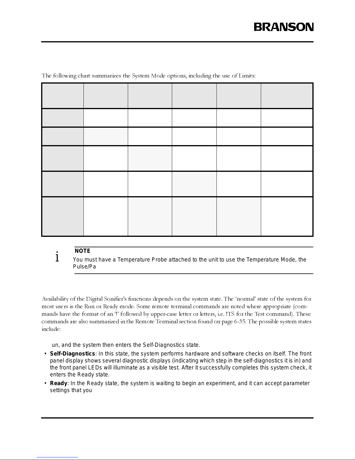
The following chart summarizes the System Mode options, including the use of Limits:
NOTE
i You must hav e a Temperature Probe attached to the un it to use the Temperature Mode, the
Pulse/Pause Mode, or to use Temperature as a Limit.
System States
Availability of the Digital Sonifier’s functions depends on the system state. The ‘normal’ state of the system for
most users is the Run or Ready mode. Some remote terminal commands are noted where appropriate (com-
mands have the format of an ‘!’ followed by upper-case letter or letters, i.e. !TS for the Test command). These
commands are also summarized in the Remote Terminal section found on page 6-35. The possible system states
include:
• Power-Up:The system enters the Power-Up state when the power switch is turned on. The fan starts to
run, and the system then enters the Self-Diagnostics state.
• Self-Diagnostics: In this state, the system performs hardware and software checks on itself. The front
panel display shows several diagn ostic displays (indicating which step in the self-diagnostics it is in) and
the front panel LEDs will illuminate as a visible test. After it successfully completes this system check, it
enters t he Ready state.
• Ready: In t he Ready state, the system is waiting to begin an experiment, and it can accept parameter
settings that y ou ent er through the keypad or the remote computer or terminal. The front panel display
Time
setting
PulseOnand
Pulse Off
settings
Max. Temp
setting
Pulse Tem p.
setting
Cycle Ends
upon...
Continuous
Mode
OFF Both OFF OFF OFF
Stop button or
remote command
Timed Mode
Your Time
parameter
Both OFF OFF or Limit OFF
Time parameter
elapses
Pulse Mode OFF or Limit
PulseOnand
Pulse Off
times
OFF or Limit OFF
Stop button or
remote command
Temperature
Mode
OFF or Limit Both OFF
maximum
Temperature
parameter
OFF
Maximum
Temperature
reached
Pulse/Pause
Mode
OFF or Limit
Optional.
The system
will rec alculate
while runni ng
the process
Max. Temp
set t o upper
temperature
for process
Pulse Temp
set to lower
temperature
for process
Stop button or
remote command
Page 52

100-214-239 Rev. A 6-5
Front Panel Controls
Digital Sonifier
shows the Amplitude setting and some parameters, and the appropriate LEDs are illuminated. The system must be in the Read y state for you to s tart a new experiment or make changes to any parameters.
• Run: After s et ti ng parame ters for y our application, pressing the Start/Stop button or sending a !ON command will Startyour setup. Ultrasonic p ower is delivered to the horn (whether continuous or pulsed), and
the front panel display will show the runtime information, including the perc entage of power used on its
bottom line as a bargraph display, and the LED next to the Start/St op button rem ains lit while the application is runni ng. If you set Limits, your application will Stop automatica lly upon reaching thos e limits.
• Test: From t he Ready state, the system enters the Test state when you press the Tes t key or issue a !TS
command to enter the Test state, causing ultrasonics to be sent to the horn. After two seconds, the system returns to the Ready state.
• Print: If you have a printer connected, and after running a cycle or testing the setup you may print a
report of your experiment. Printing is started by pressing the Print/Send key or sending a !P comma nd.
After printing, the system returns to the Ready state.
• Report: If you are using the Remote Terminal option, and after running a cycle or testing the set up, you
may se nd a report of your experiment from the system to your terminal. After the report is sent, the system returns to the Ready state.
• Hold/Pause:When you press the Hold/Pause key or issue an !Hcommand during an experim ent ortest ,
the system stops operating, stops all timer functions, and enters the Hold/Pause state. To resume operation, press the Hold/Pause key again, or issue another !H command.
• Stop/Abort: When you p ress the Start/Stop button or issue an !OFF command, the system enters th e
Stop/Abort state. The experiment or test is stop ped.
6.2 Front Panel Controls
The membrane keypad on the front panel of the Digital Sonifier allows you to enter parameters for both
System
Setup
and
Operation
of the unit during a test or experiment. You can also use a remote computer or terminal to
enter operation parameters. If a remote computer or terminal is enabled, you can lock out the keypad on the
front panel of the unit if you want to operate the unit only from the remote computer or terminal. When the
keypad is disabled through the remote computer or terminal, all keys except the Start/Stop key and the Pause
key are disabled.
There are two additional controls (Amplitude Control and Power Switch) which work with the front panel con-
trols, but are not actually part of the front panel. The remote computer or terminal may be used to control the
system as well.
6.2.1 Power Switch
The Power switch for the system is located on the front of the unit, underneath the front panel controls. It is a
simple rocker switch, on/off operation. When turned on, the front panel LEDs will light (during the power-up
sequence), and the unit’s fan will run.
Page 53
6-6 100-214-239 Rev. A
Operation
6.2.2 Temperature Probe
The optional Temperature Probe is required for the Temperature Mode, the Pulse/Pause Mode, or to use Tem-
perature as a Limit for your experiment.
6.2.3 Remote Terminal
An optional ‘Remote Terminal’ device may be used to setup and to run the experiment. The remote device can
fully control the Digital Sonifier using the built-in serial interface. Instructions for using the remote computer
or terminal and the Remote T erminal commands that you can use to enter parameters from your remote com-
puter or remote terminal are described in
Section 6.5, Remote Computer or Terminal,
beginning on page 6-35.
NOTE
i ‘Remote Terminal’commands apply to a R emote Computer or a Remote Terminal. The Setup
commands only indicate ‘Remote Terminal’ for simplicity.
6.2.4 Amplitude Control
The Amplitude control is found on the right side of the system chassis, it is a large circular control protruding
through the side of the Front Panel. It rotates up and down to regulate the Amplitude value from minimum to
maximum. The Amplitude value is displayed on the Front Panel display.
The Amplitude is displayed numerically on the bottom line of the Ready display in 1% units (to a system max-
imum of 100%), and after an experiment has been run. Amplitude may be adjusted while an experiment is run-
ning. An example of the Amplitude numerical display is shown in Figure 6.1 on page 6-7.
When the system is running, the Amplitude of the ultrasonic energy is displayed on the bottom line of the first
page of the runtime display as a bargraph, in 5% increments. An example of the bargraph display is shown in
Section 6.8, Displays During the Experiment
, on page 6-44.
Page 54
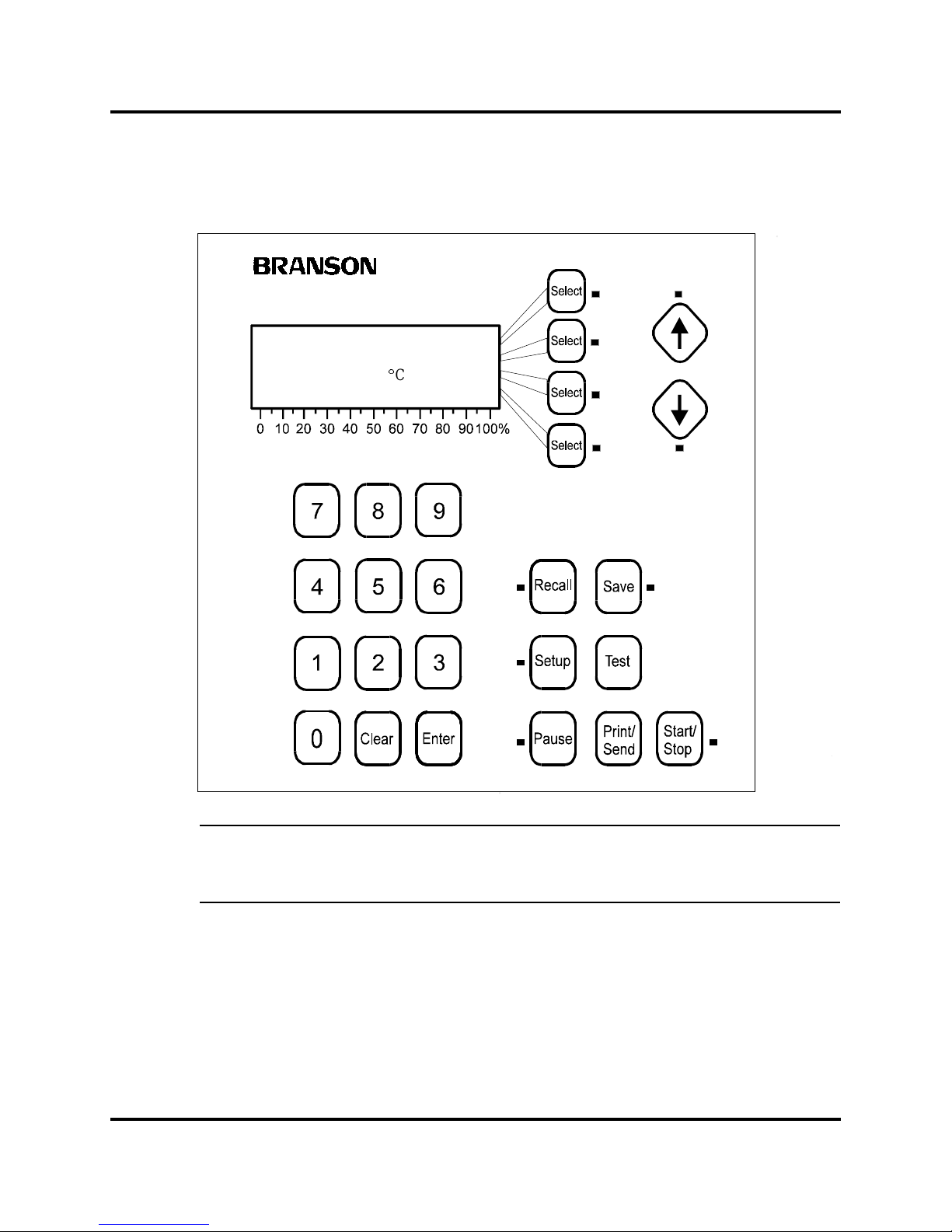
100-214-239 Rev. A 6-7
Front Panel Controls
Digital Sonifier
Figure 6.1 Digital Sonifier front panel, showing a R eady mode display i nc luding Am plitude
CAUTION
j Do not use a sharp or pointed object to press the front panel controls. The s oft-touch mem-
brane front panel can be permanently damaged.
Digital Sonifier
®
PRESET ID#__
TIME=_:__:__ hr/m/s
MAX. TEMP=___._
°
C
AMPLITUDE= 17 %
Page 55
6-8 100-214-239 Rev. A
Operation
6.2.5 Menu Navigation
When the parameter selection menu is displayed, you can use the Page Up and Page Down arrows to navigate
up and down between the pages of the menu to locate the parameters you want to change. If there are more
menu options above the page currently displayed, the Page Up arrow LED is active. If there are menu options
below the current page, the Page Down arrow LED is active.
Select buttons, when their parameters are available, will have their LED lit. The Feature buttons and Arrow keys
will have their LEDs lit when those Features or options are active.
An error beep or tone will sound if a key that is unavailable is pressed, or if a parameter that is out-of-range has
been keyed in. The system will not accept out-of-range parameters.
CAUTION
j The Start/Stop button LED is illuminated while the experiment cycle is active, even if ultra-
sonics i s not currently On (i.e. during an ‘OFF’ period in a Pul se d mode). Be careful to not
touch the Horn when a cycle is active, as it may s tart wi thout warning, and could cau se injury.
Each menu line in the display shows a parameter whose value you can change, if its associated
Select
key LED
is lit. The parameter can have either a numeric value that you enter with the numeric keys, or a choice that you
select by toggling between a set of possible selections. You select a parameter for entry by pressing the Line
Select key next to it. Then you key in the desired numeric value using the numeric keys, or the appropriate choice
from a sub-menu using the Line Select keys.
When you press a Line Select key for a numeric parameter, the least significant digit of the parameter value
flashes, and the numeric keys become active. You can:
• Key in a new value for the parameter, replacing the old value.
• Correct t he value you are entering by pressing the Clear keytoerasethevalue.Youalsouse
Clear to del ete a parameter value to turn a parameter OFF.
• Press a different Line Select key to sele ct a different parameter for entry, cancelling any
changes you have made to the first parameter.
• Press an ac ti ve Page Up or Page Down arrow key to view a different page of the Parameter
Entry menu.
•PresstheEnter key to s t ore the new value, or to store a bl ank or an OFF value if you pressed
Clear.
When you begin entering a value, the old value is replaced in the display by the new one. Once you have started
entering a value, the other Line Select keys and the Page Up and Page Down keys become inactive. The Enter
key must be pressed to leave the selected parameter.
When you press a Line Select key for a parameter that is a choice such as Yes/No or On/Off, the available values
will be displayed in the menu. You select the desired value by pressing the Line Select key next to it and then
pressing Enter to accept the value. The display then returns to the menu.
Page 56
100-214-239 Rev. A 6-9
Entering System Setup Parameters
Digital Sonifier
6.3 Entering System Setup Parameters
At System Setup, you can select and store system parameters such as time, date, language, remote operating
parameters, and printer capabilities. The System Setup parameters can only be accessed from the membrane key-
pad, not from the remote terminal, and they are not available when a test or experiment is in progress.
To enter System Setup, press the Setup function key on the keypad to display the System Setup menu. On the
menu, you will see the default values for each of the System Setup parameters. When you are finished with Sys-
tem Setup, exit the Setup menu by pressing the Setup key again. The Setup key becomes inactive, and the display
returns to the Parameter Entry menu. The Enter key must be pressed before leaving the Setup menu to store
any new parameter value.
If you change any system parameter, you must run at least a portion of a cycle in order to ‘set’ the values and
enable the Printer and Report modes.
The parameters available at System Setup and their possible values are described in the table below. Detailed
steps for each parameter are described in the pages that follow.
*The system’s Date clock is “Year 2000” and Leap Y ear compatible, and may be set up through the year 2069.
Ta ble 6-1: System Setup Parameters
Parameter Default User Selectable Options
Printer Off Off, On
Remote (Terminal) Off Off, On
Language English English, Spanish, German, Italian, French
Temperature °F °F, °C
Time of Day 12:00 00:00 - 23:59 (24-hour format only)
Date* 01/01/1998
When the Language parameter is set t o English, the date format
is MM/DD/YYYY. For any other L anguage parameter,the date for-
mat is DD/MM/YYYY.
Reports Disabled Disabled, Enabl ed
Baud Rate
(remote terminal)
9600 9600, 1200, 2400, 19200
Data bits
(remote terminal)
8N/A
Parity
(remote Terminal)
None N/A
Model (printer) Panasonic Epson
Page 57
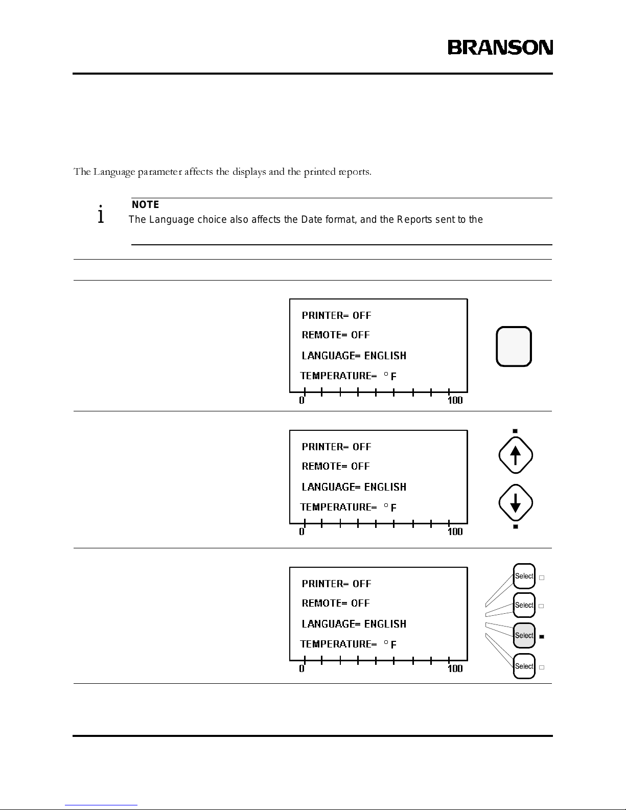
6-10 100-214-239 R ev. A
Operation
System Setup - Language
The Language parameter affects the displays and the printed reports.
NOTE
i The Language choice also affects the Date format, and the Reports sent to the P rinter and/
or the Remote Terminal. See page 6-12 for additional information on Setting the D ate.
Take this action… To get this result…
Press the Setup key to display the
System S etup menu. Its LED lights.
Use the Up and Down arrow keys, if
necessary, to display the line showing the
Language parameter.
Press theLineSelectkey thatcorrespond s
to Language.
Setup
Page 58
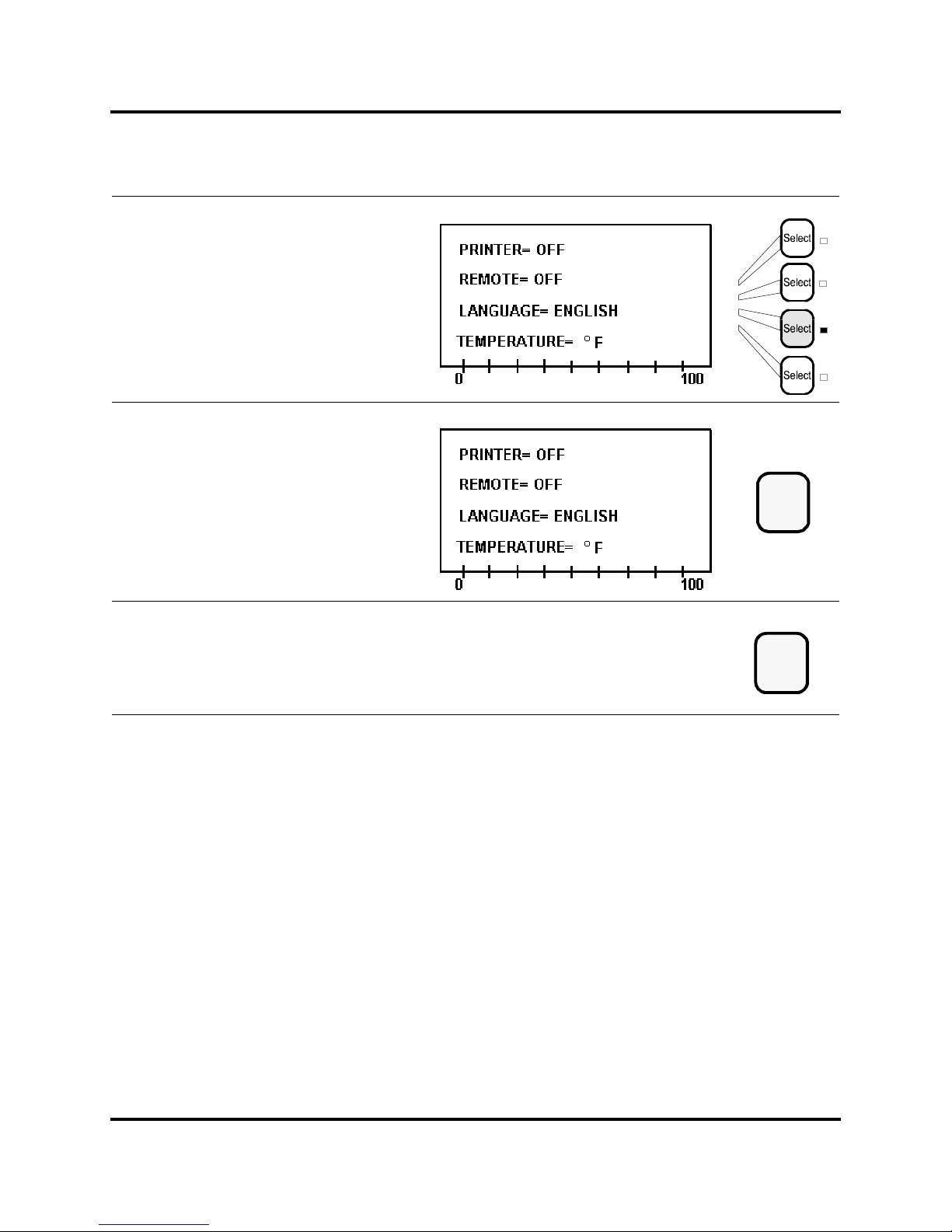
100-214-239 Rev. A 6-11
Entering System Setup Parameters
Digital Sonifier
Press the same Line Select k ey ag ain
to toggle am ong the p ossible v alues for
Language: English, Spanish, German,
Italian, or French.
Press the Enter key to store the choice for
Language.
Press the Setup key to exit the
System S etup menu. The Setup LED
extinguishes.
Enter
Setup
Page 59
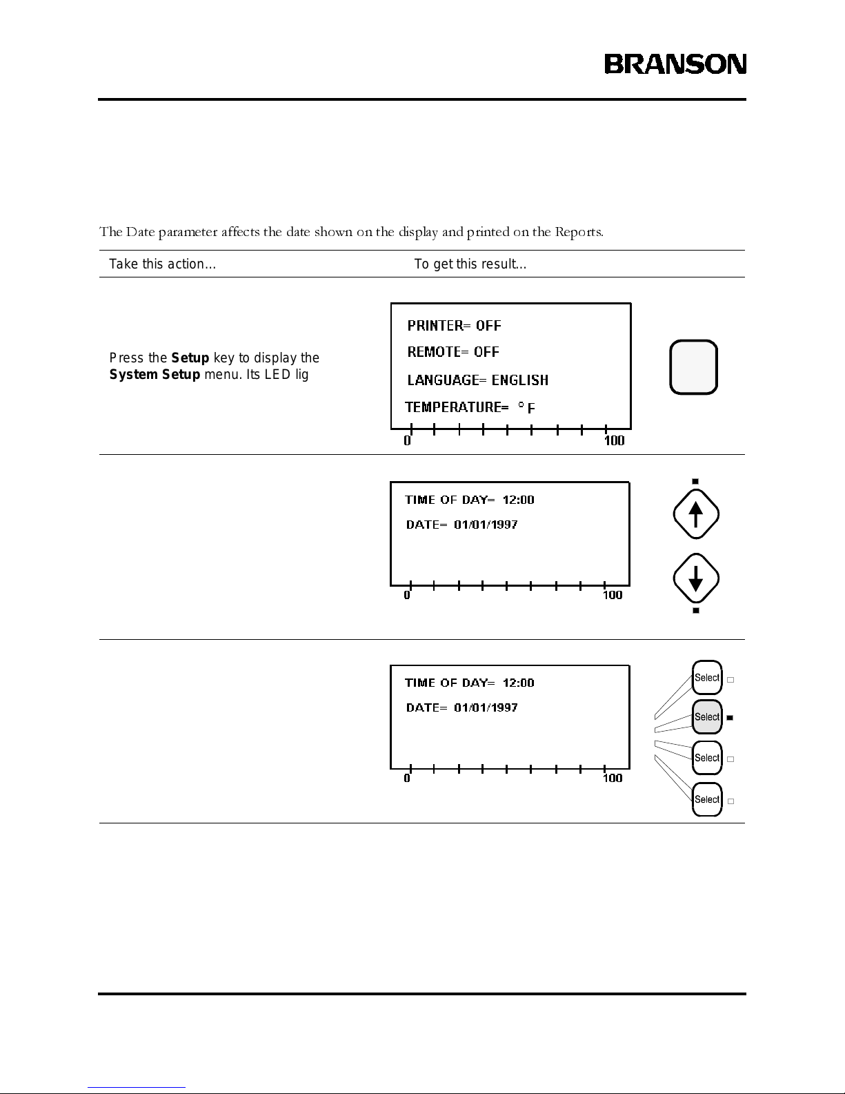
6-12 100-214-239 R ev. A
Operation
System Setup - Date
The Date parameter affects the date shown on the display and printed on the Reports.
Take this action… To get this result…
Press the Setup key to display the
System S etup menu. Its LED lights.
Use the Up and Down arrow keys, if
necessary, to display the line showing the
Date parameter.
Press theLineSelectkey thatcorrespond s
to Date.
Setup
Page 60

100-214-239 Rev. A 6-13
Entering System Setup Parameters
Digital Sonifier
Use the num eric keys to enter the current
date, using an American or Euro pean date
format as appropriate. If you set E nglish as
the Language parameter, the system uses
the American date format(MM/DD/YYYY).
Otherwise, it uses the European format
(DD/MM/YYYY).
Press the Enter key to store the value
for Date, or press the Clear key to re-enter
the date.
Press the Setup key to exit the
System S etup menu. The Setup LED
extinguishes.
789
456
123
0
Clear
Enter
or
Setup
Page 61

6-14 100-214-239 R ev. A
Operation
System Setup - Time of Day
The Time of Day parameter affects the Time shown on the display and printed on the Reports (24-hour format
only).
Take this action… To get this result…
Press the Setup key to display the
System S etup menu. Its LED lights.
Use the Up and Down arrow keys, if
necessary, to display the line showing the
Time of Day parameter.
Press theLineSelectkey thatcorrespond s
to Time of Day.
Setup
Page 62

100-214-239 Rev. A 6-15
Entering System Setup Parameters
Digital Sonifier
Use the num eric keys to enter the
current t ime , based on a 24-hour clock.
Press the Enter key to store the value
for Time of Day,orpresstheClear key to
re-enter the time.
Press the Setup key to exit the
System S etup menu. The Setup LED
extinguishes.
789
456
123
0
Clear
Enter
or
Setup
Page 63
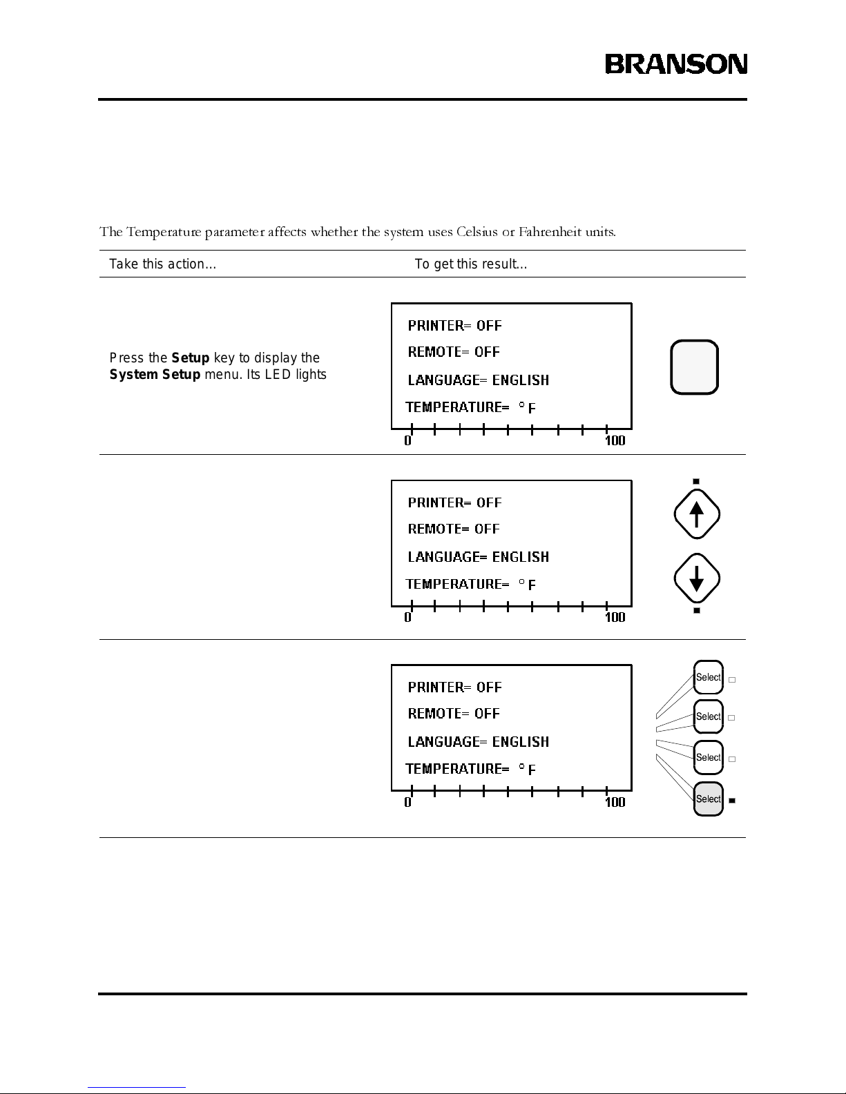
6-16 100-214-239 R ev. A
Operation
System Setup - Te mperature Un its
The Temperature parameter affects whether the system uses Celsius or Fahrenheit units.
Take this action… To get this result…
Press the Setup key to display the
System S etup menu. Its LED lights.
Use the Up and Down arrow keys, if
necessary, to displ ay the line showing
the Temperature parameter.
Press theLineSelectkey thatcorrespond s
to Temperature.
Setup
Page 64
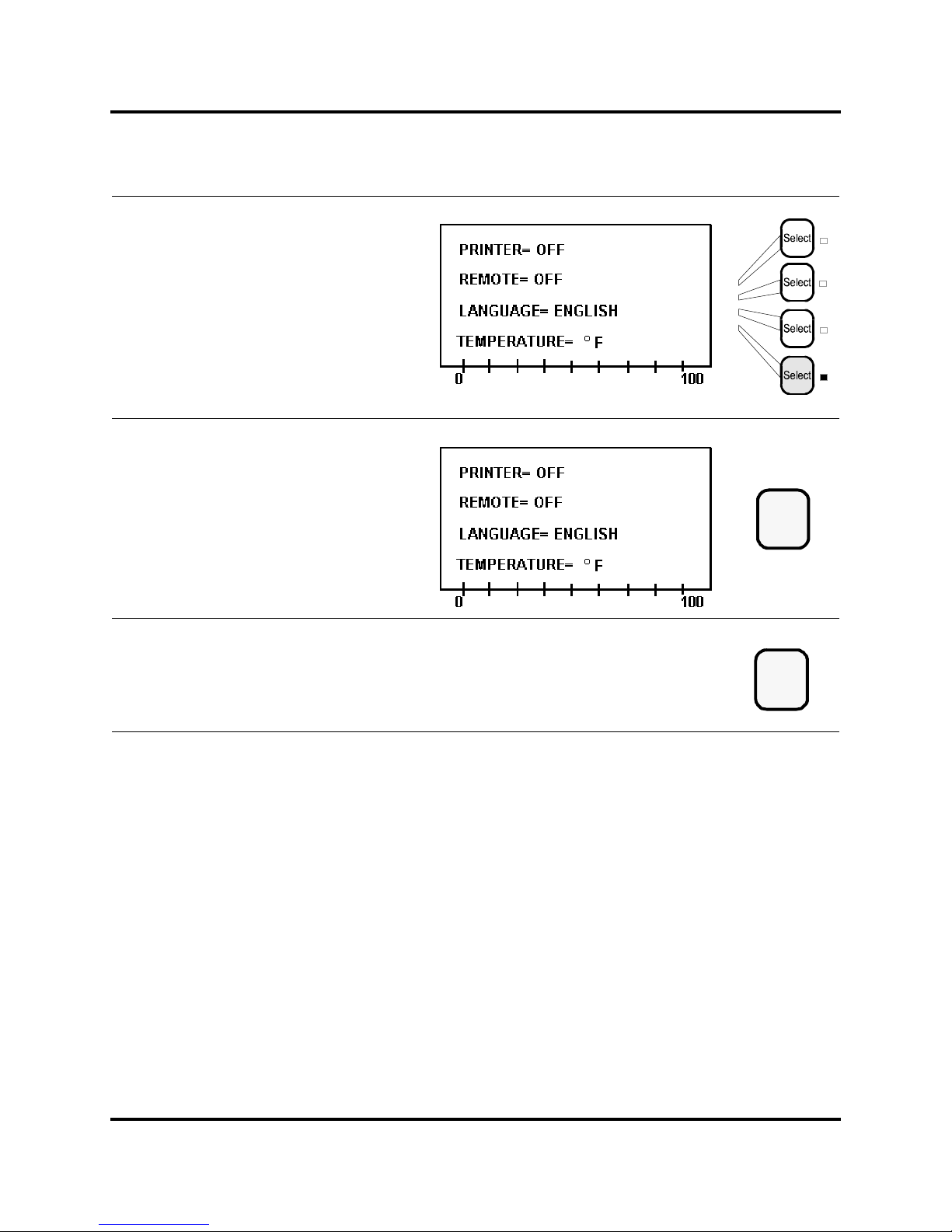
100-214-239 Rev. A 6-17
Entering System Setup Parameters
Digital Sonifier
Press the same Line Select k ey ag ain
to toggle between t he pos sible values fo r
Temperature units: °F or °C.
Press the Enter key to store the value
for Temperature units.
Press the Setup key to exit the
System S etup menu. The Setup LED
extinguishes.
Enter
Setup
Page 65
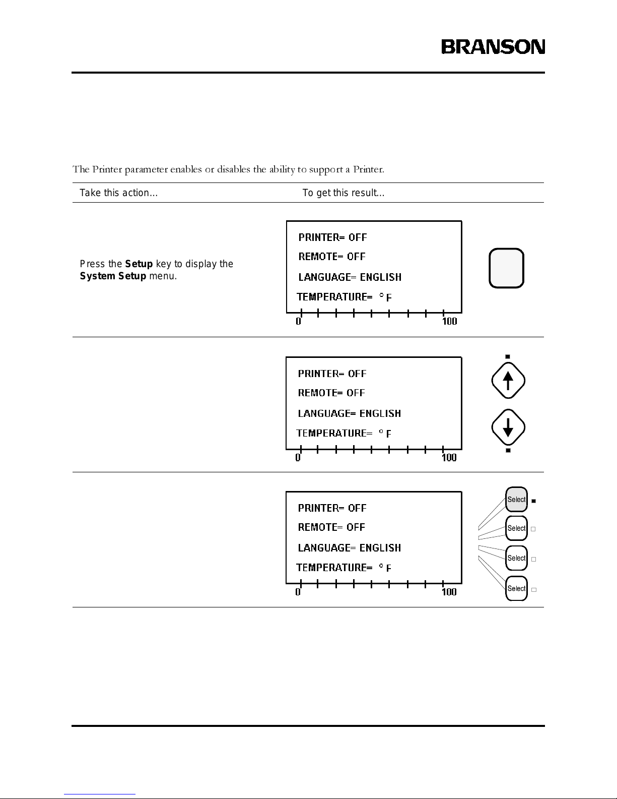
6-18 100-214-239 R ev. A
Operation
System Setup - Printer
The Printer parameter enables or disables the ability to support a Printer.
Take this action… To get this result…
Press the Setup key to display the
System S etup menu. Its LED lights.
Use the Up and Down arrow keys, if
necessary, to displ ay the line showing
the Printer parameter.
Press theLineSelectkey thatcorrespond s
to Printer.
Setup
Page 66
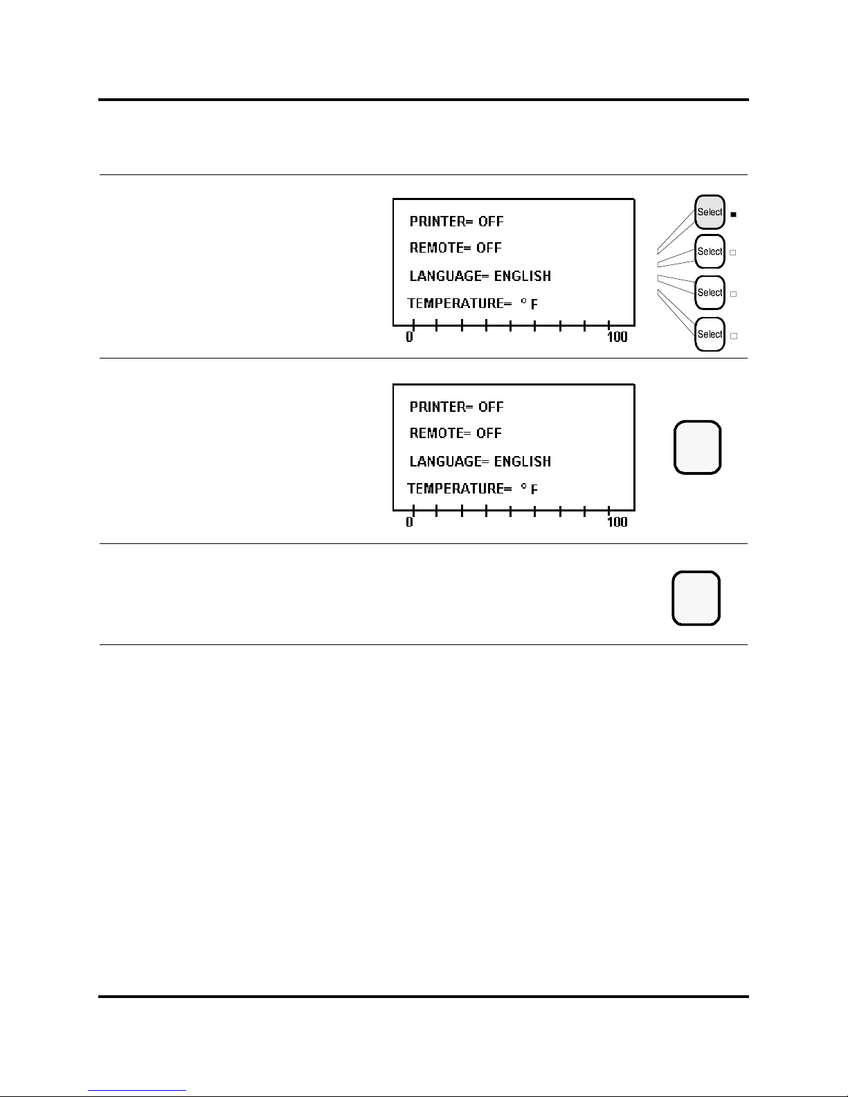
100-214-239 Rev. A 6-19
Entering System Setup Parameters
Digital Sonifier
Press the same Line Selectkeyto
toggle between the two poss ible values
for Printer: On if a printer will be enabled,
or Off if i t will be disabled.
Press the Enter key to store the value
for Printer.
Press the Setup key to exit the
System S etup menu. The Setup LED
extinguishes.
Enter
Setup
Page 67
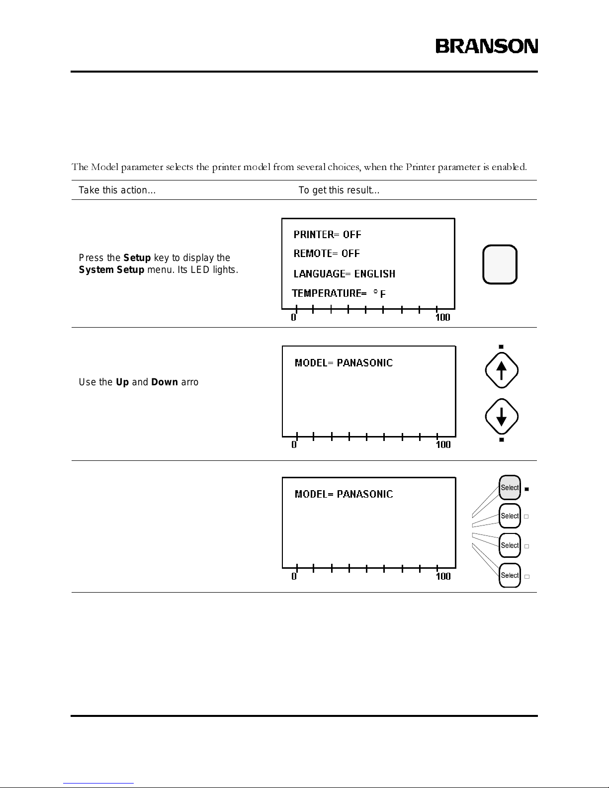
6-20 100-214-239 R ev. A
Operation
System Setup - Printer Model
The Model parameter selects the printer model from several choices, when the Printer parameter is enabled.
Take this action… To get this result…
Press the Setup key to display the
System S etup menu. Its LED lights.
Use the Up and Down arrow keys, if
necessary, to displ ay the line showing
the Model parameter.
Press theLineSelectkey thatcorrespond s
to Model.
Setup
Page 68
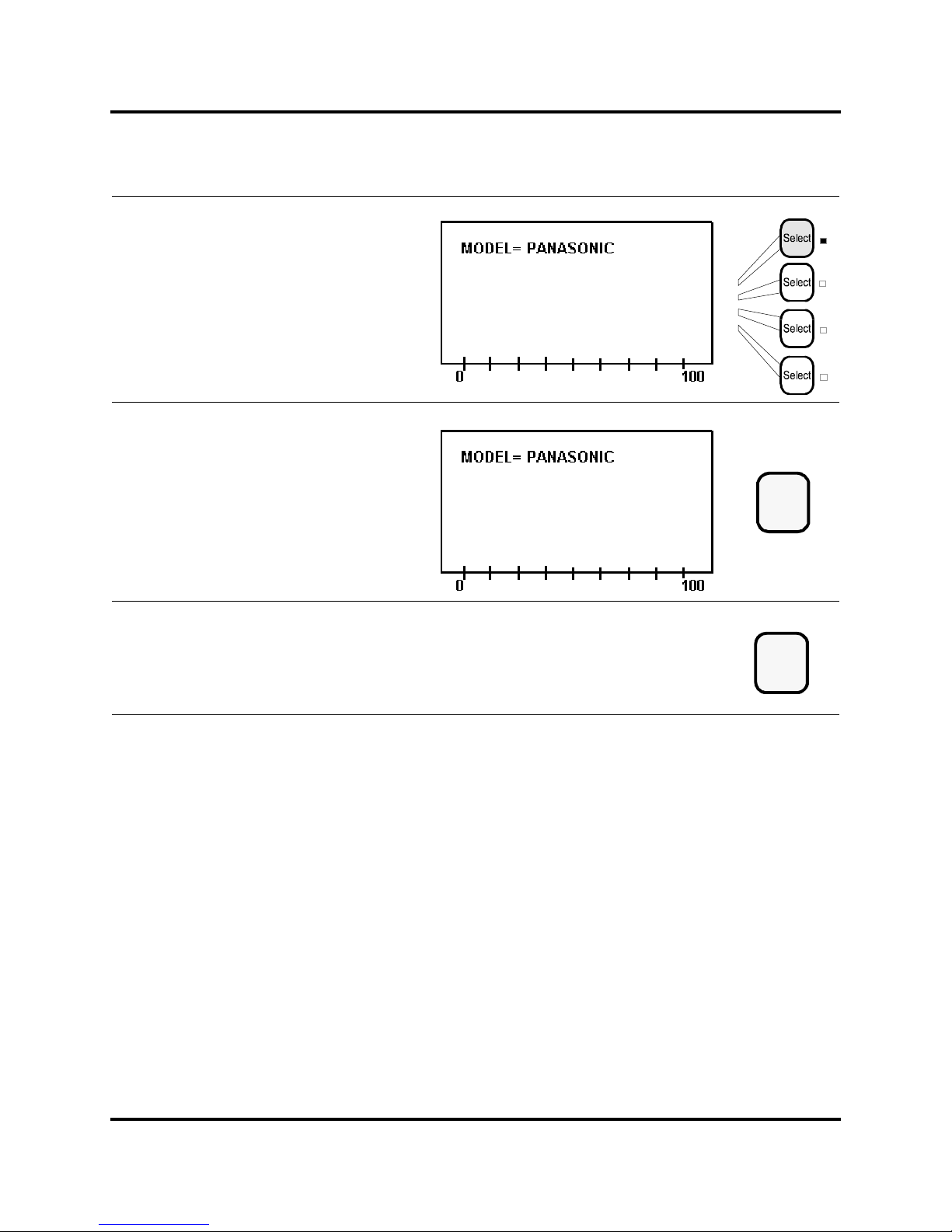
100-214-239 Rev. A 6-21
Entering System Setup Parameters
Digital Sonifier
Press the same Line Select k ey ag ain to
toggle among the possible values for
your pri nter Model: P anasonic, Epson,
or IBM.
Press the Enter key to store the value
for Model.
Press the Setup key to exit the
System S etup menu. The Setup LED
extinguishes.
Enter
Setup
Page 69
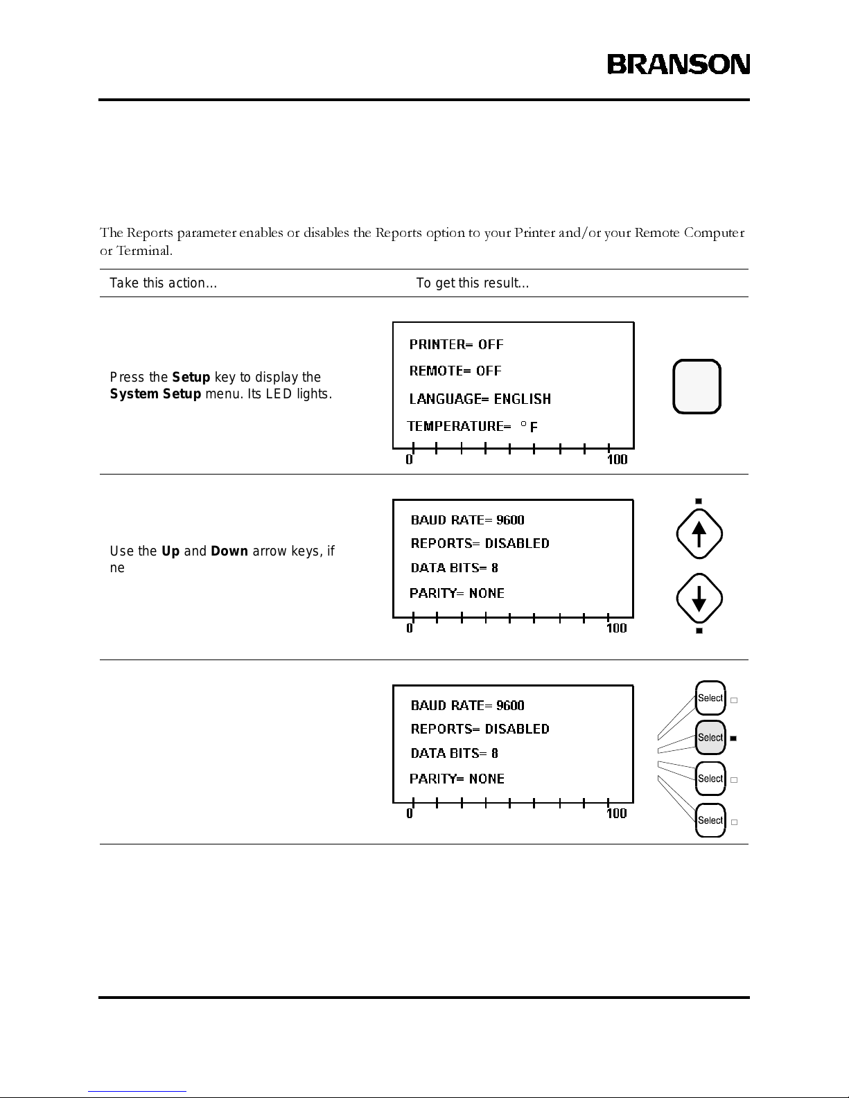
6-22 100-214-239 R ev. A
Operation
System Setup - Reports
The Reports parameter enables or disables the Reports option to your Printer and/or your Remote Computer
or Terminal.
Take this action… To get this result…
Press the Setup key to display the
System S etup menu. Its LED lights.
Use the Up and Down arrow keys, if
necessary, to displ ay the line showing
the Reports parameter.
Press theLineSelectkey thatcorrespond s
to Reports.
Setup
Page 70
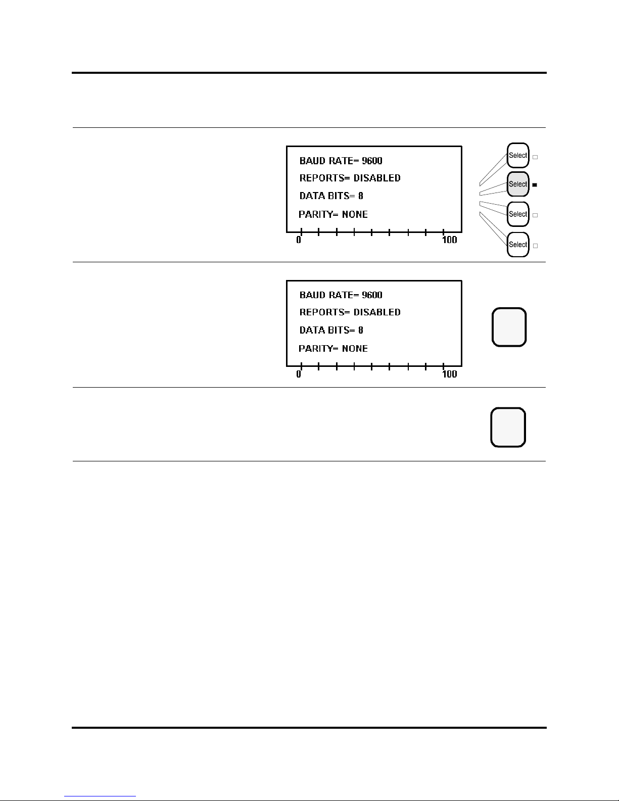
100-214-239 Rev. A 6-23
Entering System Setup Parameters
Digital Sonifier
Press the same Line Select k ey ag ain
to toggle between t he pos sible values fo r
Reports: Enabled or Disabled.
Press the Enter key to store the value
for Reports.
Press the Setup key to exit the
System S etup menu. The Setup LED
extinguishes.
Enter
Setup
Page 71
6-24 100-214-239 R ev. A
Operation
6.4 Entering Operation Parameters
You can enter Operation parameters through the keypad or through the remote terminal, if the terminal is
enabled in the System Setup menu. Only the Amplitude value (using the Amplitude knob on the side of the
chassis) may be changed when an experiment is running.
When the System is in the Ready mode (e.g. after power-up or after a test or experiment is performed) it displays
the first page of the Parameter Entry menu. In the Parameter Entry menu, you can enter parameters for your
test or experiment. When a Line Select key for a parameter is available and may be selected, its LED is lit.
Entering Parameters from the Keypad
When in the Ready mode, you can press any available
Line Select
key on the front panel to select a parameter
for modification. There are a total of two (2) pages of parameters; use the Arrow Up or Arrow Down keys to
see more parameter choices on the display.
Use the number keys to key in a parameter value, and press
Enter
to store the value or accept the choice, or
press
Clear
to clear a stored numeric entry or to disable a choice and then press
Enter
to store the cleared or
disabled parameter value. The System will not accept parameter values that are out of the range of the system.
Once the parameters have been changed and stored, the experiment is ready to run with the new values.
6.4.1 Presets
Once you have a set of parameters stored for a given experiment, you can save that setup as a Preset. Up to 20
Presets may be saved, using the Save and Recall functions described in the following sections. Presets are saved
and recalled using a number, 01 to 20. Presets save all parameters for the setup except for the Amplitude param-
eter. Presets are saved until they are over-written or cleared, and are maintained in memory even if the system
is turned off or unplugged.
6.4.2 Remote Terminal entry
The Remote Terminal may be used to change any of the operation parameters (except for Amplitude). Instruc-
tions and commands that you use to enter parameters from the remote terminal are described in
Section 6.5,
Remote Computer or Terminal,
beginning on page 6-35.
Reviewing Parameters on the Remote Terminal
If you have disabled the front-panel keypad by sending a !KL from the remote terminal, only the
Start/Stop
and
Pause
keys are active. If both the keypad and the remote computer or terminal are active, the parameters
displayed on the front panel will be similar to those described in this section, but any values you enter on the
keypad will be updated at the remote computer or terminal only when you request them by issuing the Recall
Parameters (!RP) command. See
Section 6.5, Remote Computer or Terminal,
beginning on page 6-35 for more infor-
mation.
Page 72
100-214-239 Rev. A 6-25
Entering Operation Parameters
Digital Sonifier
The Operation parameters that you can set from the keypad are described in the following table. Detailed steps
for each parameter are described in the pages that follow.
Ta ble 6-2: Operation Parameters
Parameter Description Valid Entries
Preset ID#
When you view a set of parameters that was saved
using theSave function, Preset ID# contains the preset
identificationnumber under which t he parameters were
saved. The number is not av ailable f or en try.
ThePresetIDwillbefollowedbyanasterisk(*)ifyou
change any of the paramet ers.
01–20
Time
The length of time the experiment should run, in hours,
minutes and seconds.
0:00:01 – 9:59:59
Max. Temp.
This parameter is available onl y if a temperature probe
is connected t o the system . The temperat ure units
(Fahrenheit or Celsius) aredetermined by the setting of
the Temperature parameter, selected during System
Setup. If no probe is connected, the value will display
as TEMP OFF.
32.0° – 212.0°F
or 0.0° – 100.0°C
Amplitude
The c urrent Am plitude setting (manually set u sing the
Amplitude control on the s ide of the unit). The amplitude affects the amount of power applied during the
experiment.
10% minimum to
100% maximum
Pulse Temp
This parameter is available for entering the Pulse Temperature if a temperature probe is connected. Entering
a value for this parameter puts the system in the
Pulse/Pause mode. The temperature units (Fahrenheit
or Ce lsius) are determined by the setting of the Tem-
perature parameter, selected during System Setup. If
a probe is not connected, t he Pulse Temp value will be
displayed as TEMP OFF.
32.0°F or 0.0 °C to
3° below Max. Temp.
parameter
Pulse On
In Pulse mode, the length of time in tenths of seconds
that ultrasonics wi ll be On
0.1 to 59.9 seconds
Pulse Off
In Pulse mode, the length of time in tenths of seconds
that ultrasonics wi ll be Off
0.1 to 59.9 seconds
Page 73
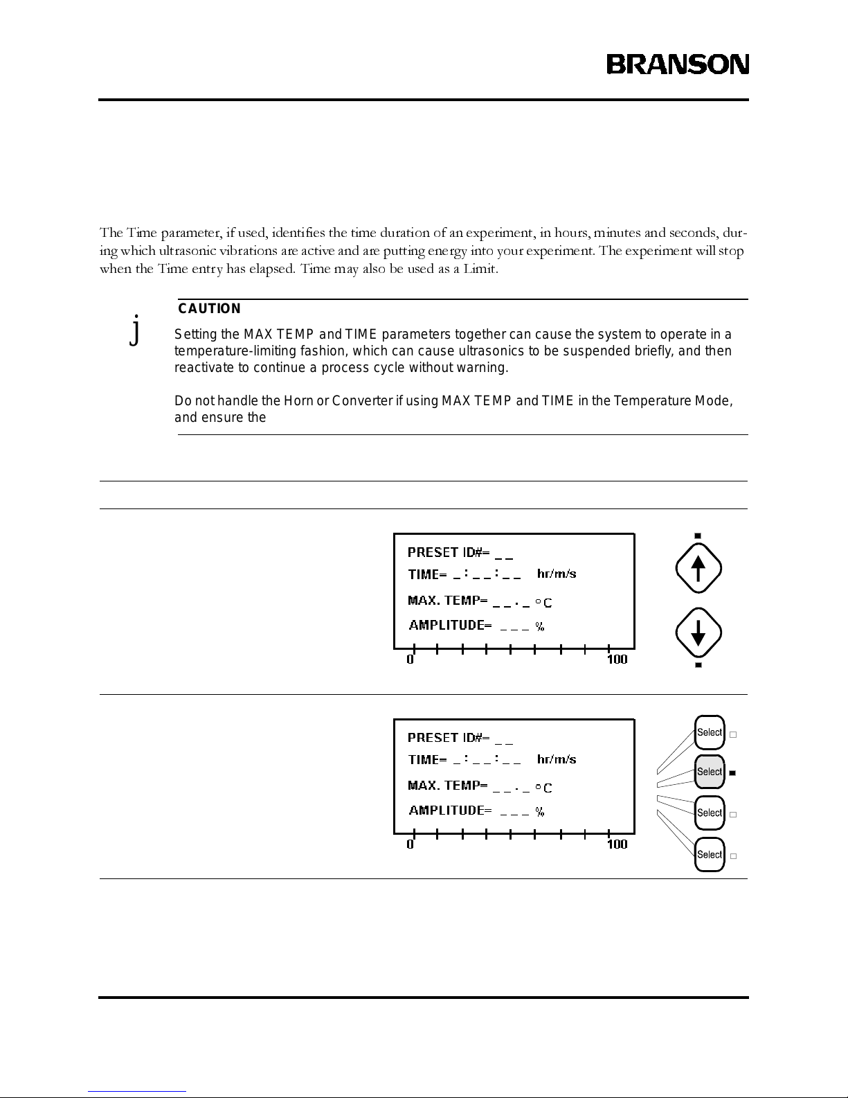
6-26 100-214-239 R ev. A
Operation
Parameter En try - Time
The Time parameter, if used, identifies the time duration of an experiment, in hours, minutes and seconds, dur-
ing which ultrasonic vibrations are active and are putting energy into your experiment. The experiment will stop
when the Time entry has elapsed. Time may also be used as a Limit.
CAUTION
j Settingthe MAX TEMP and TIME parameters together can cause the syst em to operate in a
temperature-limiting fashion, which can c ause u ltrason ics to be suspended briefly, and then
reactivate to continue a process cycle without warning.
Do not handlethe Horn or Con ve rter if using MAX TEMP and TIME in the Temperat ure Mode,
and ensure the proces s cycle is Stopped before touching the Horn, or injury could occur.
Take this action… To get this result…
Use the Up and Down arrow keys, if
necessary, to display the line showing the
Time parameter.
Press theLineSelectkey thatcorrespond s
to Time.
Page 74

100-214-239 Rev. A 6-27
Entering Operation Parameters
Digital Sonifier
NOTE
i If using the Time parameter as a limit in Pulsed Mode, the elapsed time will be greater than
the Time parameter value, since the Time value is the duration that ultrasonic vibrations are
active (t he ‘Pulse On’ time) and does not include the ‘Pulse Off’ time.
Use the num eric keys to enter a value
for Time, how long you want t he exp eriment to run.
Press the Enter key to store the value
for Time, or press the Clear keyto re-enter
the time.
789
456
123
0
Clear
Enter
or
Page 75

6-28 100-214-239 R ev. A
Operation
Parameter Ent ry - Maximum Temperature
The Maximum Temperature parameter, if used, identifies the maximum temperature allowed in the experiment.
Maximum Temperature may be used as a Limit for all modes except Pulse/Pause Mode.
CAUTION
j Settingthe MAX TEMP and TIME parameters together can cause the syst em to operate in a
temperature-limiting fashion, which can c ause u ltrason ics to be suspended briefly, and then
reactivate to continue a process cycle without warning.
Do not handlethe Horn or Con ve rter if using MAX TEMP and TIME in the Temperat ure Mode,
and ensure the proces s cycle is Stopped before touching the Horn, or injury could occur.
If used with the Pulse/Pause mode or using Maximum Temperature and Time parameters together, Maximum
Temperature sets the upper temperature parameter of these modes, at which point the experiment will pause to
allow cooling, but does not cause the experiment to Stop.
Take this action… To get this result…
Use the Up and Down arrow keys, if
necessary, to displ ay the line showing
the Max. Temp parameter.
Press theLineSelectkey thatcorrespond s
to Max. Temp.
Page 76
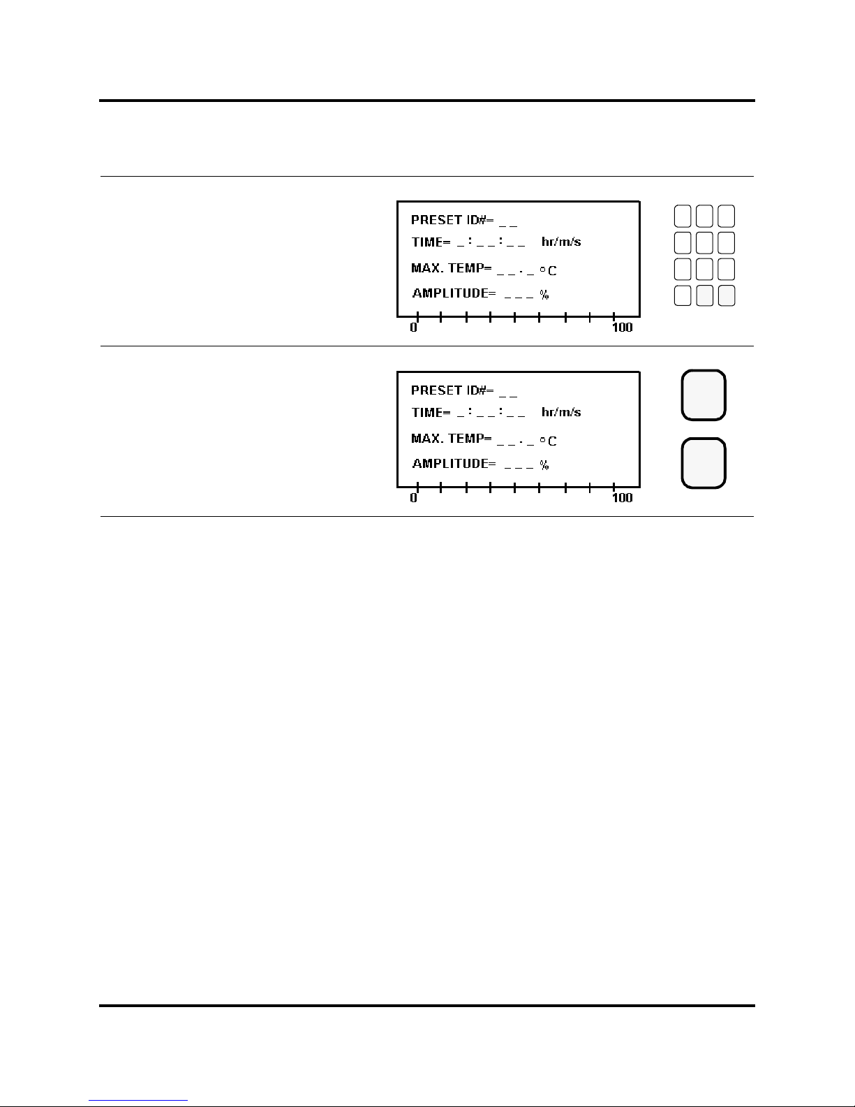
100-214-239 Rev. A 6-29
Entering Operation Parameters
Digital Sonifier
Use the num eric keys to enter the value
for Max. Temp.
Press the Enter key to store the value
for Max Temp,orpresstheClear key to
correct and re-ente r the temperature.
789
456
123
0
Clear
Enter
or
Page 77
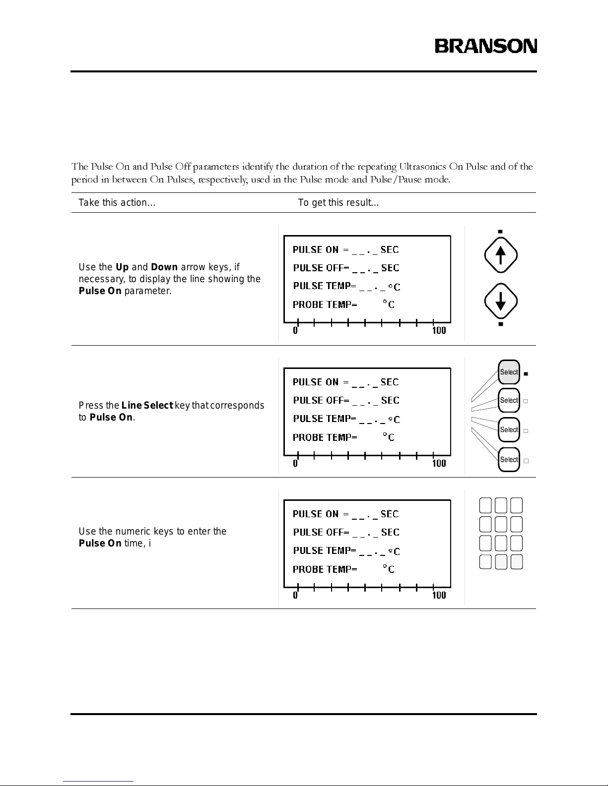
6-30 100-214-239 R ev. A
Operation
Parameter Entry - Pulse On and Pulse Off
The Pulse On and Pulse Off parameters identify the duration of the repeating Ultrasonics On Pulse and of the
period in between On Pulses, respectively, used in the Pulse mode and Pulse/Pause mode.
Take this action… To get this result…
Use the Up and Down arrow keys, if
necessary, to display the line showing the
Pulse On parameter.
Press theLineSelectkey thatcorrespond s
to Pulse On.
Use the num eric keys to enter the
Pulse On time, in tenths of seconds ,
that the ultrasonic pulse will be on.
789
456
123
0
Page 78
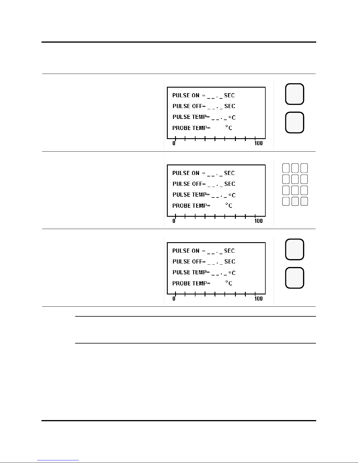
100-214-239 Rev. A 6-31
Entering Operation Parameters
Digital Sonifier
NOTE
i A shortcut tip: If you Clear either P ulse time parameter and press Enter, both values will be
cleared. You do not need to Clear both parameters.
Press the Enter key to store the value
for Pulse On, or press the Clear key to
re-enter the va lue.
As s oon as you have pressed Enter
to store the Pulse On value, the system
moves to the Pulse Off parameter lin e.
Use the numeric keys to enter the
Pulse Off time, in tenths of second s.
Press the Enter key to store the value
for Pulse Off, or press th e Cl ear key to
re-enter the va lue.
Clear
Enter
or
789
456
123
0
Clear
Enter
or
Page 79
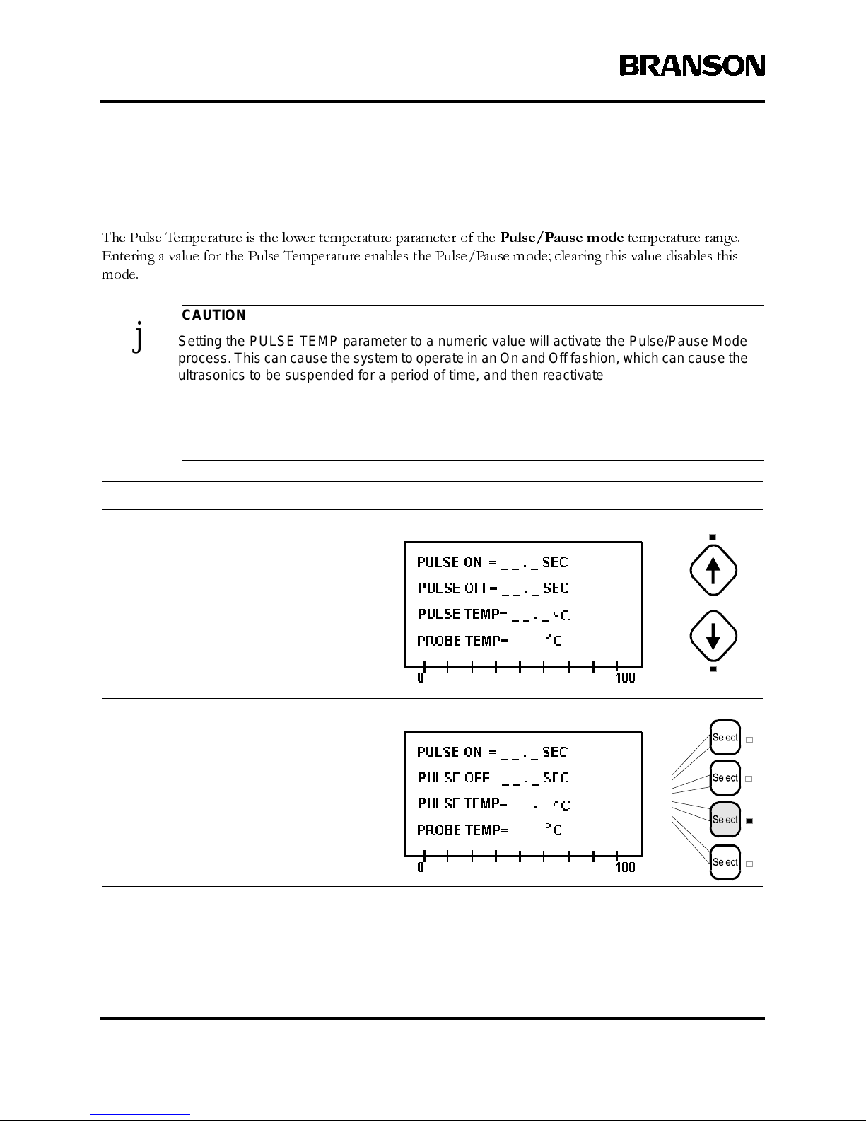
6-32 100-214-239 R ev. A
Operation
Parameter Entry - Pulse Temperature
The Pulse Temperature is the lower temperature parameter of the
Pulse/Pause mode
temperature range.
Entering a value for the Pulse Temperature enables the Pulse/Pause mode; clearing this value disables this
mode.
CAUTION
j Setting the PULSE TEMP parameter to a numeric value will activate the Pulse/Pause Mode
process.This can cause the system to operate in an On and Off fashion, which can cause the
ultrasonics t o be su sp ended for a period of time, and then reactivate to continue a process
cycle without warning.
Do not handle the Horn or Converter if the Pul se /Pause Mode is activated and running, and
ensure the proces s cycle is Stopped before touching the Horn, or injury could occur.
Take this action… To get this result…
Use the Up and Down arrow keys, if
necessary, to displ ay the line showing
the Pulse Temp parameter.
Press theLineSelectkey thatcorrespond s
to Pulse Temp.
Page 80
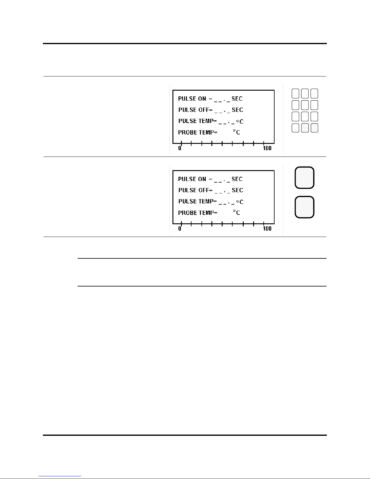
100-214-239 Rev. A 6-33
Entering Operation Parameters
Digital Sonifier
NOTE
i The P ROBE TEM P value is a display of the temperature of the optional Temperat ure Probe.
If the Temperature Probe is not connected, the display will show TEMP OFF instead.
Use the num eric keys to enter the
Pulse Temp.
Press the Enter key to store the value
for Pulse Temp,orpresstheClear key
to correct and re-enter the value.
789
456
123
0
Clear
Enter
or
Page 81
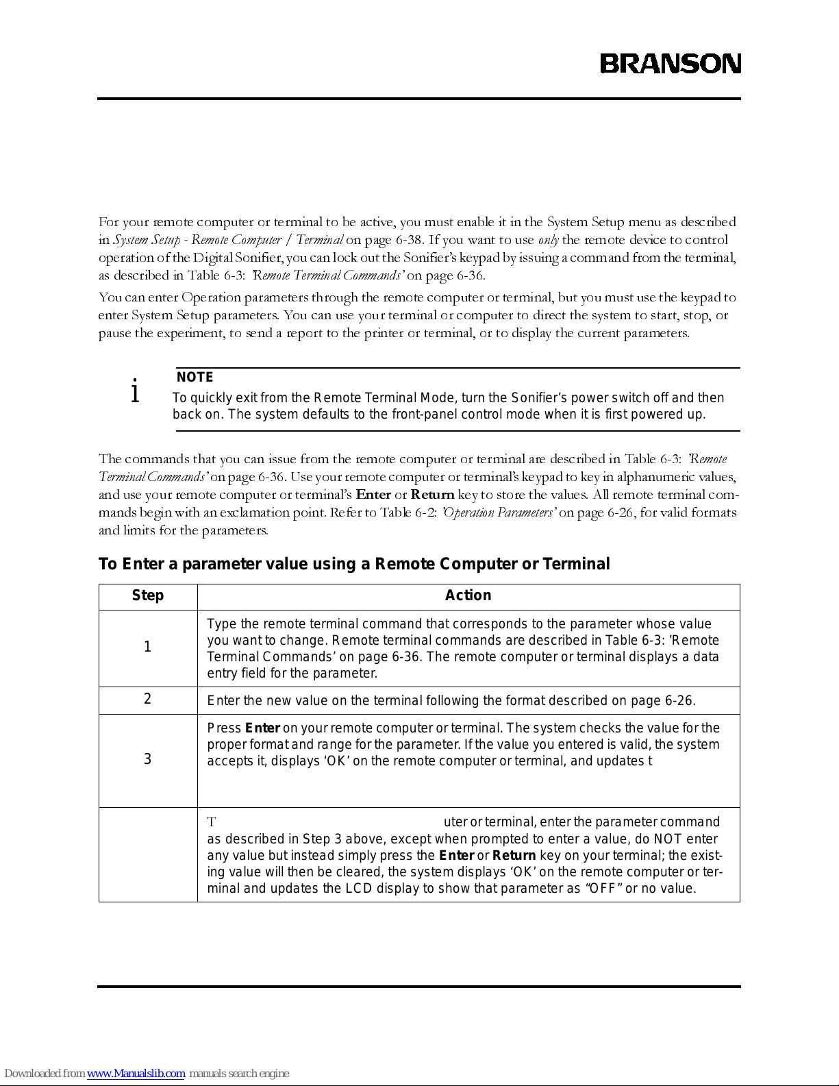
6-34 100-214-239 R ev. A
Operation
6.5 Remote Com puter or Terminal
For your remote computer or terminal to be active, you must enable it in the System Setup menu as described
in
System Setup - Remote Computer / Terminal
on page 6-38. If you want to use
only
the remote device to control
operation of the Digital Sonifier, you can lock out the Sonifier’s keypad by issuing a command from the terminal,
as described in Table 6-3:
’Remote Terminal Commands’
on page 6-36.
You can enter Operation parameters through the remote computer or terminal, but you must use the keypad to
enter System Setup parameters. You can use your terminal or computer to direct the system to start, stop, or
pause the experiment, to send a report to the printer or terminal, or to display the current parameters.
NOTE
i To quickly exit from the Remote Terminal Mode, turn the Sonifier’s power switch off and then
back on . The system defaults t o the front-panel control mode when it is first p owered up.
The commands that you can issue from the remote computer or terminal are described in Table 6-3:
’Remote
Terminal Commands’
on page 6-36. Use your remote computer or terminal’s keypad to key in alphanumeric values,
and use your remote computer or terminal’s
Enter
or
Return
key to store the values. All remote terminal com-
mands begin with an exclamation point. Refer to Table 6-2:
’Operation Parameters’
on page 6-26, for valid formats
and limits for the parameters.
To Enter a parameter value using a Remote Computer or Terminal
Step Action
1
Type the remote terminal command that corresponds to the parameter whose value
you want to change. Remote terminal commands are described in Table 6-3: ’Remote
Te rmin al Commands ’ on page 6-36. The remote computer or t erminal displays a data
entry f ield for the parameter.
2
Enter the n ew value on the terminal following the format described on page 6-26.
3
PressEnteron your remote computeror terminal. The system checks the value for the
proper format and range for the parameter.If the v alue you entered is valid,the system
accepts it, displays ‘OK’ on the remote computer or terminal, and updates the LCD display on the unit’s control panel if the active page contains that parameter. If the value
is invalid, the system displays an error message.
4
T
oClear avalue using the remote computer or terminal,enter the parameter command
as described i n Step 3 above, ex c ept when p ro mpted to enter a value, do NOT enter
any value but instead simply press the Enter or Return key on your terminal; the existing value will then be cleared, the system displays ‘OK’ on the remote computer or terminal and updates the LCD display to show that parameter as “OFF” or no value.
Page 82

100-214-239 Rev. A 6-35
Remote Computer or Terminal
Digital Sonifier
Ta ble 6-3: Remote Term inal Commands
Command Terminal Displays User / System Action
!T TIME=
Type a v alue for the tim e, and press Enter on your
remote c omputer or terminal.
!MT MAX TEMP=
Type the maximum temperature, and press Enter on
your remote computer or terminal.
!PO PULSE ON=
Typethe time period w hen power will be on, and press
Enter on your remote computer or terminal.
!POF PULSE OFF=
Typethe time period when power will be off, and press
Enter on your remote computer or terminal.
!PPT PULSE TEMP=
Type th e Pulse Temperature, and press Enter on your
remote c omputer or terminal.
!SV PRESET ID#
Type the identifying number under which you want to
save the preset parameter values, and press Enter on
your remote computer or terminal.
!R PRESET ID #
Type the preset ID number for the saved set of parameters you want to use, and press Enter on your remote
computer or terminal.
!RP List of param eters
The sy stem displays all the current parameters on the
remote c omputer or terminal.
!S Report
The system sends a report to the remote computer or
terminal.
!P N/A The system sends a report to the printer.
!H EXPERIMENT PAUSED
The experiment is currently paused .
Issuing another pause command from the remote
terminal will caus e the experiment to resume, if t he
experiment is c urrently paused.
!TS
TUNING TEST
PLEASE WAIT 2 SEC.
Ultrasonics are activated for a tw o-s ec ond test.
!KL * KEYPAD DISABLED *
The keypad is disabled, or enabled if it was already disabled.
!ON
EXPERIMENT RUNNING
(displayed ev ery 5 seconds)
The ex periment is running from a remote command.
!OFF EXPERIM ENT STOPPED The experiment has been stopped.
Page 83

6-36 100-214-239 R ev. A
Operation
System Setup - Remote Computer / Terminal
The Remote parameter enables or disables support for a customer-provided Remote Computer or Terminal.
Take this action… To get this result…
Pressthe Setup key to display the System
Setup menu. Its LED lights.
Use the Up and Down arrow keys, if necessary, to display the line showing the
Remote parameter.
Press theLineSelectkey thatcorrespond s
to Remote.
Setup
Page 84
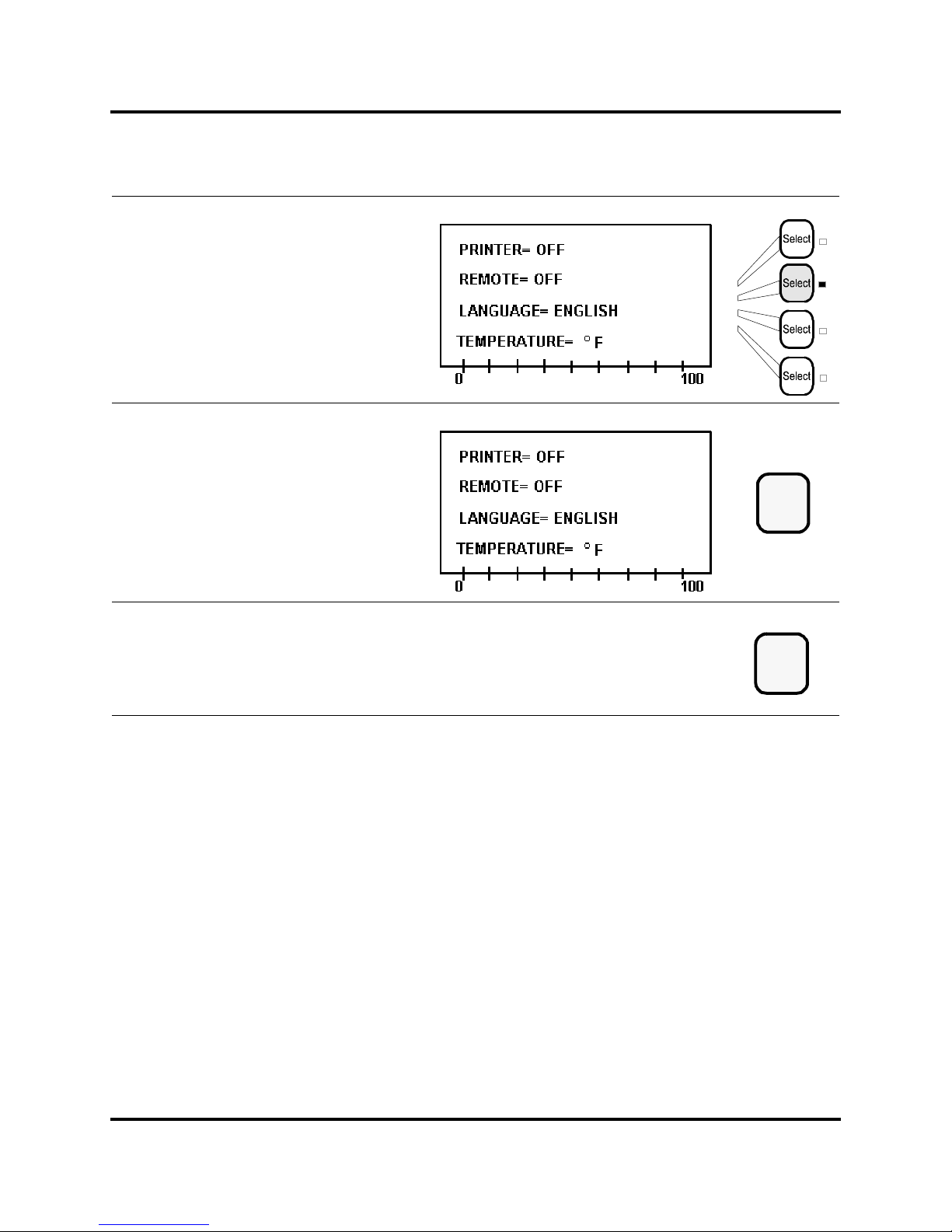
100-214-239 Rev. A 6-37
Remote Computer or Terminal
Digital Sonifier
Press the same Line Select k ey to toggle
between the t wo poss ible values for
Remote: On if a remote comput er or terminal will be enabled, Off if it will be disabled.
Press the Enter key to store the value for
Remote.
Press the Setup key to exit the System
Setup menu. The Setup LED extinguishes.
Enter
Setup
Page 85
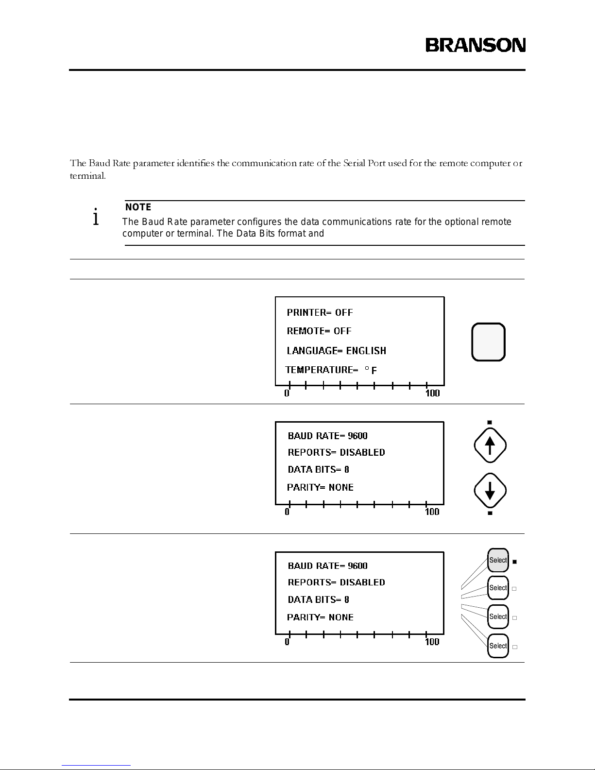
6-38 100-214-239 R ev. A
Operation
System Setup - Baud Rate
The Baud Rate parameter identifies the communication rate of the Serial Port used for the remote computer or
terminal.
NOTE
i The B aud Rate paramet er configures the data communications rate for the optional remote
computer or terminal. The Data Bits format and Parity parameters are n on-adjustable.
Take this action… To get this result…
Pressthe Setup key to display the System
Setup menu. Its LED lights.
Use the Up and Down arrow keys, if necessary, to display the line showing the Baud
Rate parameter.
Press theLineSelectkey thatcorrespond s
to Baud Rate.
Setup
Page 86
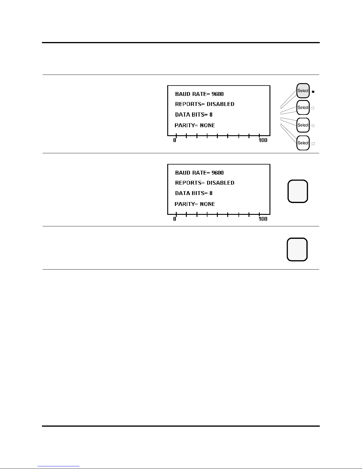
100-214-239 Rev. A 6-39
Remote Computer or Terminal
Digital Sonifier
Press the same Line Select k ey ag ain to
toggle among the possib le values for Baud
Rate: 1200, 2400, 9600, or 19200.
Press the Enter keytostorethevaluefor
Baud Rate.
Press the Setup key to exit the System
Setup menu. The Setup LED extinguishes.
Enter
Setup
Page 87
6-40 100-214-239 R ev. A
Operation
6.6 Save and Recall Presets
The Save and Recall functions allow you to enter a set of Operation parameters and save them under a unique
ID number. To repeat an experiment or test using the same set of parameters without having to re-enter them
(with the exception of the Amplitude setting), you can use the ID number to recall the saved parameters.
To Save a set of parameters as a Preset, follow this procedure:
NOTE
i The system will always confirm the ‘overwrite’ procedure as a level of security for all presets,
even if the use r had not previously used that Preset ID.
To Recall a saved Preset, follow this procedure:
Step Action to Save Presets
1
Press theSave key on the keypad, or t ypean !SV commandfrom the remote computer
or term inal. The system d isplays the Save To: entry sc r een.
2
Using the keypad, enter a value for the preset ID number. You can us e values from 01
to 20.
3
Press Enter to save the value. The system displays a message asking you to confirm
that you want to overwrite the existing preset (even if y ou chose an unused P res et ID).
Press the ap propriate Select key for Yes to replace the previous preset with the one
you are set ting and Save your Setup, o r No to return to the previous sc reen and give
the current prese t a different ID number.
Step Action to Recall a Saved Preset
1
Press the Recall key or type an !R command from the remote computer or terminal.
The system displays the Recall entry sc reen.
2
Using the keypad or the number keys on yo ur Remote Terminal or Computer, ent er in
thedesired presetnumber.
3
PressEnter.The system reloads the preset information to memory and is ready to run
with those parameters. The syste m returns to the previous page of the screen.
Page 88

100-214-239 Rev. A 6-41
Printing/Sending Reports
Digital Sonifier
6.7 Printing/Sending Reports
After an experiment, the system can produce a report showing the date and time of the experiment, the param-
eters in effect, and statistics for energy, power, amplitude, and temperature. The report data remains available
until you start a new experiment, or until you change any System Setup parameters. Reports must be turned on
in the Setup menu. If you want to run a report, you must do so
before
the next experiment is started and
before
you change any System Setup parameters. You can send the report to a printer or to the remote computer or
terminal. The report has the following format:
TIME = XX:XX DATE = XX/XX/XXXX
PRESET ID# = value
TIME = value
MAX. TEMP = value
PULSE ON = value
PULSE OFF = value
PULSE TEMP = value
ENERGY = energy delivered, in Joules
PEAK POWER = power delivered, in watts
AMPLITUDE = last amplitude %
LAST TEMPERATURE READING = temperature TIME = elapsed time
HIGHEST TEMPERATURE = temperature TIME = elapsed time
Page 89
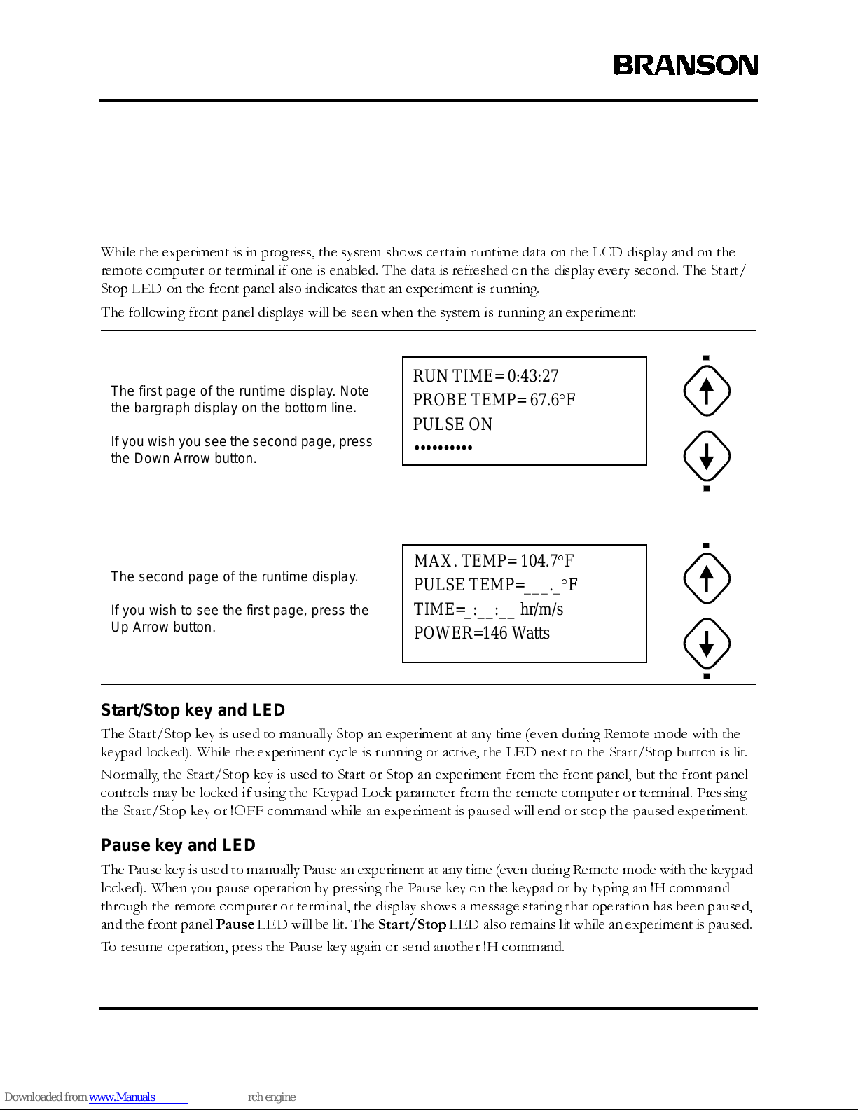
6-42 100-214-239 R ev. A
Operation
6.8 Displays During the Experiment
Runtime Displays
While the experiment is in progress, the system shows certain runtime data on the LCD display and on the
remote computer or terminal if one is enabled. The data is refreshed on the display every second. The Start/
Stop LED on the front panel also indicates that an experiment is running.
The following front panel displays will be seen when the system is running an experiment:
Star t/Stop key and LED
The Start/Stop key is used to manually Stop an experiment at any time (even during Remote mode with the
keypad locked). While the experiment cycle is running or active, the LED next to the Start/Stop button is lit.
Normally, the Start/Stop key is used to Start or Stop an experiment from the front panel, but the front panel
controls may be locked if using the Keypad Lock parameter from the remote computer or terminal. Pressing
the Start/Stop key or !OFF command while an experiment is paused will end or stop the paused experiment.
Pause key and LED
The Pause key is used to manually Pause an experiment at any time (even during Remote mode with the keypad
locked). When you pause operation by pressing the Pause key on the keypad or by typing an !H command
through the remote computer or terminal, the display shows a message stating that operation has been paused,
and the front panel
Pause
LED will be lit. The
Start/Stop
LED also remains lit while an experiment is paused.
To resume operation, press the Pause key again or send another !H command.
The f irs t page of the runtime display. Note
the bargraph display on the bot tom line.
If you wish you see the second page, press
the Down Arrow button.
The s ec ond page of the runtime displa y.
If you wish to see the first page, press the
Up Arrow button.
RUN TIME= 0:43:27
PROBE TEMP= 67.6°F
PULSE ON
••••••••••
MAX. TEMP= 104.7°F
PULSE TEMP=___._°F
TIME=_:__:__ hr/m/s
POWER=146 Watts
Page 90
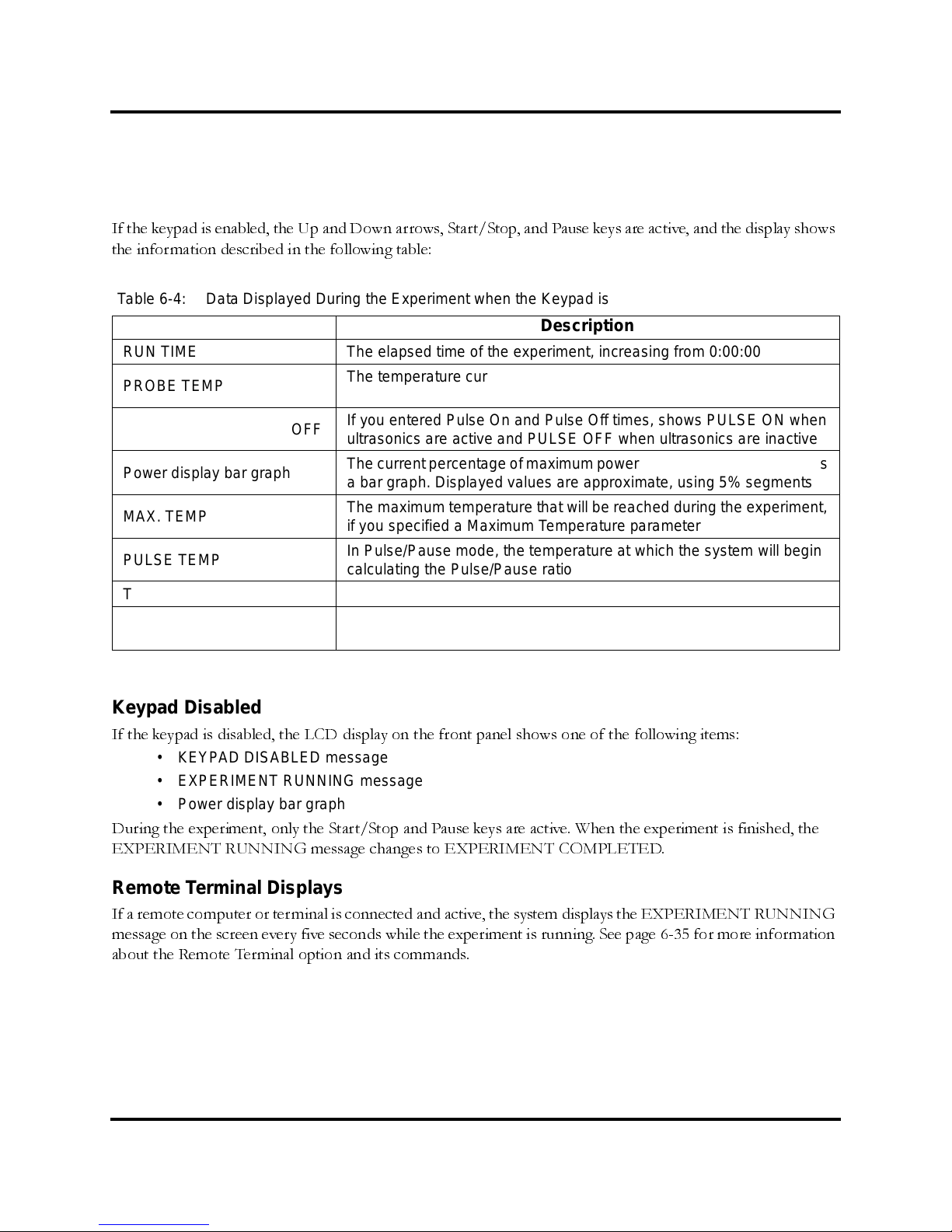
100-214-239 Rev. A 6-43
Displays During the Experimen t
Digital Sonifier
Keypad Enabled
If the keypad is enabled, the Up and Down arrows, Start/Stop, and Pause keys are active, and the display shows
the information described in the following table:
Keypad Disabled
If the keypad is disabled, the LCD display on the front panel shows one of the following items:
• KEYPAD DISABLED message
• EXPERIMENT RUNNING message
• Power display bar graph
During the experiment, only the Start/Stop and Pause keys are active. When the experiment is finished, the
EXPERIMENT RUNNING message changes to EXPERIMENT COMPLETED.
Remote T erminal Displays
If a remote computer or terminal is connected and active, the system displays the EXPERIMENT RUNNING
message on the screen every five seconds while the experiment is running. See page 6-35 for more information
about the Remote Terminal option and its commands.
Ta ble 6-4: Data Displayed During the Ex perim ent when the Keypad is Enabled
Display Description
RUN TIME The elapsed time of the experiment, increasing from 0:00:00
PROBE TEMP
The temperature curren tly being read by t he temperat ure probe, if one
is connected
PULSE ON and PULSE OFF
If you entered Pulse On and Pulse Off times, shows PULSE ON when
ultrasonics are act ive and PULSE OFF when ultrasonics are inactive
Power display bar graph
The current percentage of maximum power being u se d, re pres ente d as
a bar grap h. Displayed values are approximate, using 5 % segments
MAX. TEMP
The maximum temperature that will be reached during the experiment,
if you specified a Maximum Temperature parameter
PULSE TEMP
In Pulse/P ause mode , the temperature at which the system will begin
calculating the Pulse/Pause ratio
TIME The t im e limit for the experiment, if one was entered
POWER
The power, in watts, being cons umed by the Horn at any m oment. During a PULSE OFF period, the powe r goes to zero
Page 91
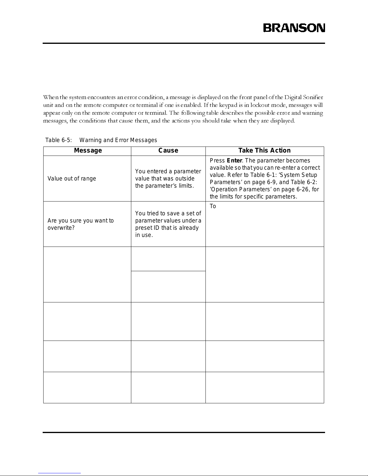
6-44 100-214-239 R ev. A
Operation
6.9 Warning and Error Messages
When the system encounters an error condition, a message is displayed on the front panel of the Digital Sonifier
unit and on the remote computer or terminal if one is enabled. If the keypad is in lockout mode, messages will
appear only on the remote computer or terminal. The following table describes the possible error and warning
messages, the conditions that cause them, and the actions you should take when they are displayed.
Ta ble 6-5: Warning and Error Messages
Message Cause Take This Action
Value out of range
You entered a parameter
value that was outside
the parameter’s limits.
Press Enter. The parameter beco mes
availableso thatyou can re-entera correct
value. Refer to Table 6-1: ’System Setup
Parameters’ on page 6-9, and Table 6-2:
’Operation Parameters’ on page 6-26, for
the limits for specific parameters.
Are you sure you want to
overwrite?
You t ried to save a set of
parametervalues under a
preset ID that is already
in use.
To ov erwrite t he existing values i n the Preset ID, press Line Selector key #3. To
enter a different preset ID, press Line
Selector k ey #4. The previous screen is
displayed for you to ente r a different preset ID.
Printer error
Youissuedaprintcommand, but there was no
response from the printer.
Check that the printer is correctly connected and turned on. Check the Model
parameter to see that the correct printer
modelhas been set.Check thatthe Printer
parameter is set to On.
The system was turned
on with the ‘Printer = On’
but with no printer c onnected.
THE DATA FORMAT
ENTEREDFOR parameter IS
INCORRECT!PLEASE
ENTER AGAIN.
The parameter value that
you entered was in the
wrong format.
Enterthe value inthe correct format.Refer
to Table 6-1: ’System Setup Parameters’
on page 6-9, and Table 6-2: ’Operat ion
Parameters’ on page 6-26 for valid parameter formats.
INVALID COMMAND
RECEIVED, PLEASE ENTER
AGAIN.
You entered an invalid
command through the
remote computer or terminal.
Enter a va lid command. Ref er to
Table 6-2:’Operation Parameters’ on page
6-26 for valid remote terminal commands.
THE SYSTEM C OULD NOT
INTERPRET THE LAST
TRANSMISSIO N. PLEASE
TRY SENDING AGAIN.
The system could not
interpret the data that
was sent from theremote
computer or terminal.
Send the data again.
Page 92
100-214-239 Rev. A 7-1
Maintenance and Troubleshooting
Digital Sonifier
7 Maintenance
7.1 Maintenance and Troubleshooting --------------7-1
7.2 Reconditioning the Stack Interface --------------7-2
7.3 Troubleshooting Charts -------------------7-5
7.4 Interconnect Diagram---------------------7-9
7.1 Maintenance and Troubleshooting
The Digital Sonifier is a self-contained system that requires no internal servicing, except for a
protective fuse, and there are no user serviceable parts inside the unit. The ultrasonic tooling
(horns and tips) may require periodic inspection and maintenance to ensure optimum perfor-
mance. T h e tooling components are subj ect to wear and may require re pl ac ement after a period
of time, depending on the applications.
If you have a problem operating your unit, refer to Table 1:
’System Trouble Analysis Chart’
on
page 7-7 to locate the symptom that most clearly describes your problem.
Tip Erosion
Horn tips can erode. Tip erosion is a side effect of the cavitation process that occurs when liq-
uids are exposed to ultrasonic energy. The rate of erosion depends on the intensity of power
applied, the corrosiveness of the liquid being treated, and the amount of use.
Periodically inspecting the tip will help you recognize erosion early. As erosion progresses, the
color of the tip changes from its original polished appearance, first to light grey and then to
dark grey. Concentric rings begin to appear, and finally the tip becomes rough and pitted,
resulting in loss of power output. As it erodes, the tip can also introduce metal particles into
the solution, causing it to darken or discolor.
Eventually, erosion may become significant, at which point the tip will require replacement.
Page 93
7-2 100-214-239 Rev. A
Maintenance
Power Output Loss
There are several conditions that can cause a decrease in or loss of power output, including
• operating with a faul ty power supply or poor electrical connection
• operating with a loos e horn-c onv erter connect ion, and
• operating w ith a cracked or corroded horn/tip assembly.
If your unit indicates a decrease in power output, first check the Converter Cable connections,
then take the following steps to ensure that the horn/tip assembly is not loose or cracked or
corroded.
Fretting corrosion refers to a black, crusty build-up, resulting from friction between metal parts
that appears on the mating metal surfaces. Corrosion can reduce or alter system performance.
Examine all mating surfaces (microtip to converter, disruptor to converter, tip to horn) and
wipe the surfaces clean with a clean cloth or paper towel.
The 250/450 Sonifier does not require tuning. Tuning is done in the factory and cannot be per-
formed by the operator.
7.2 Reconditioning the Stack Interface
Ultrasonic system components work most efficiently when the mating surfaces of the Con-
verter-and-Horn combination (also called a “Stack”) are flat, in solid contact, and free from
fretting corrosion. Fretting corrosion refers to a black, crusty build-up, resulting from friction
between metal parts, that appears on the Stack mating surfaces. Poor contact between mating
surfaces wastes power output, makes tuning difficult, increases noise and heat, and may cause
damage to the converter.
Page 94
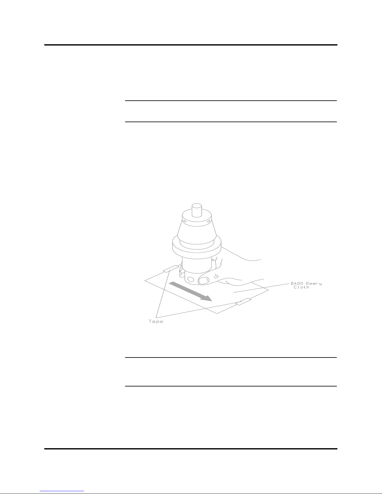
100-214-239 Rev. A 7-3
Reconditioning the Stack Interface
Digital Sonifier
7.2.1 Refacing the Mating Surfaces
NOTE
i Never clean the Convert er or Horn mating surfaces with a buffing wheel.
1. Disassemble the Converter / Horn Stackand wipe the mating surfaces with a c lean
cloth or paper towel.
2. Examine all mating surfaces. Ifany m ating surface shows co rrosion or a hard, dark
deposit, rec ondition it.
3. If nec es s ary, remove the threaded stud from the part.
4. Tape a clean sheet of #400 (or finer) grit emery clot h to a clean, smooth, flat surface (suc h as a sheet of plate glass).
NOTE
i Be careful to avoid tilting the part and losing flatness of the surface. Doing so
may make t he s y stem inoperat ive, du e to improper mating surfaces.
Page 95
7-4 100-214-239 Rev. A
Maintenance
Lapping Procedure
5. Holding the part to recondition, place the interface surface on the emery cloth.
Grasp the part at the lower end, with your thumb over the s panner-wrenc h hole,
and lap the part in a straight line across the emery cl oth.
NOTE
i Do not apply downward pressure. The weight of t he part alone provides suf-
ficient pressure.
6. Rotate the part 120 degrees (1/3) to the next hole.
7. Stroke the part an equal n umber of times at each rotation (2 or 3).
8. Pick up the part and lap it once or t wice in the same direction.
9. Rotate the part 120 degrees, placing your thumb over the spanner-wrench hole,
and lap t he part the same number of times as described above.
10. Rotate the part another 120 degrees to the next spanner-wrenc h hole, and repeat
the l apping procedure.
Re-examine the mating surface. If necessary, repeat steps 5 through 10 until you remove most
of the contaminant. This should not require more than two to three complete rotations for an
aluminum horn or booster; a titanium component may require more rotations.
7.2.2 Horn Tip Cleaning
Take the following steps to clean the horn’s tip threads:
1. If the horn has a replaceabl e tip, remove it and clean its threads in alcohol.
2. Swab out the end of the horn threads with a cotton swab and alcohol.
3. Make sure both the horn and the tip are clean and completely dry before you reassemble them.
Refer to the Tip installation procedures for information on tightening the Tips. This is found
in
Section 4.4, Assembling the Equipment,
beginning on page 4-9.
4. Use a s panner wrench on the horn and an open-end wrench on t he t ip toi ns tall the
tip u sing the following torque specifications:
1/4-20 — tighten at 90-inch-lbs/10.16 Newton-meters
3/8-24 — tighten at 180 inch-lbs/20.33 Newton-meters
Page 96
100-214-239 Rev. A 7-5
Troubleshooting Charts
Digital Sonifier
7.2.3 Stud Reinsertion
The Stud is intended to be a use-only-once part, as it has knurls on its end which ‘bite’ into the
relatively softer horn material. The studs are also specially designed to withstand ultrasonic
stresses. If you must temporarily re-use a used stud, especially with an Aluminum horn, it is
very important to clean the threads and the horn of the previous shavings.
1. Using a file card or wire brush, clean any chips from the knurled end of the stud.
2. Using a clean c loth or towel, clean the threaded hole.
3. Examine the knurled end of the s tud. If worn, replace the stud. Examine the stud
and threaded hole for st ripped threads . Do not use a damaged ultrasonic horn or
converter.
NOTE
i Threaded studs cannot be re-used in titanium horns.
4. Clean t he s tud and the threaded hole before reinserting it.
5. Apply one drop of Loc t ite to the stud and insert it into the horn.
6. Retighten the stud. Use the following torque specifications:
After the Stud has been reinserted, you can reassemble the Horn to the Converter. Follow the
same procedure as found in the Installation section of this manual. See
Section 4.4, Assembling
the Equipment,
beginning on page 4-9.
7.3 Troubleshooting Charts
Use the following troubleshooting charts for possible problem conditions and resolutions. The
charts are based on the assumption that the proper setup and operation instructions have been
followed and/or the system was working and then developed a problem.
Stud Size Torque Specification Stud EDP numb er
3/8-24 x 11/4 in 290 in lbs/33 Nm 100-098-121
3/8-24 x 11/2 in 290 in lbs/33 Nm 100-098-120
1/2-20 x 11/4 in 450 in lbs/51 Nm 100-098-370
1/2-20 x 11/2 in 450 in lbs/51 Nm 100-098-123
Page 97
7-6 100-214-239 Rev. A
Maintenance
Ta ble 1: System Trouble Analysis Chart
Symptom Probable Cause Corrective Action
Main power fuse fa ils or
circuit breaker trips when
system is plugged into
electrical outlet.
• Cordset has failed • Replace cordset
• Power Switch has failed.
• Line filter has failed.
• Return for repair
Display screen d oes not
appear when unit is
turned on. Fan does not
operate.
•System isunplugged ormain
power is missing
• Correct powe r problem
• Unit fu s e has blown (it
should not under normal c onditions)
• Replace fuse
• Cordset ha s failed • Replace cordset
• Power Switch has failed
• Line filter has failed
• Unit failed due to connection
to incorrect input voltage
• Return for repair
Fan does not operate
whensystem isturned on.
Display sc reen appears.
• Fan motor has failed • Return for repair
Fuse fails when systemis
turned on.
• Fu se is under-rated
• Mains Voltage is incorrect
• Fan motorhas failed
• Power supply module has
failed
• Unit failed due to connection
to incorrect input voltage
• Verify voltage sourc e is
correct. Dam age may
occur if co nnected to
wrong v oltage source
• Replace fus e w ith correct value and retry; or
return for repair
Ultrasonic power is not
delivered t o the horn.
• Ultrasonic power su pply
module has failed
• Digital controls have failed
• Return for repair
Unusual noise f rom Horn
when ultrasonics are on
• Horn or Tip is loose, or it is
contacting a sol id object
• Reposition horn
• Remove, ex amine, and
clean tip; reinstall tip
• Horn or tip has failed • Replace horn or tip
Page 98
100-214-239 Rev. A 7-7
Troubleshooting Charts
Digital Sonifier
Ultrasonic p ower is
absent or inconsistent
• Fo reign ma terial is between
horn surface and replaceable
tip. If horn is hot to the touch,
problem may exist with corroded tip-to-ho rn interface
• Remove, ex amine, and
clean tip; reinstall tip
• Replace tip if corrosion
is excessive
•IfusedwithaTreatment
Chamber, horn tip is not
immersed adequately
• Verify the Treatment
Chamber setup, adjust as
needed
• Tip is loose or worn out
• Horn is loose or has failed
• Tighten or replace
defective tip or horn
• Horn stud is loose or has
failed
• Loose or brok en studs
must be replaced
• Replace defective horn
• Converter cable connection
is loos e or has failed
• Tighten connector to
Converter
• Ret urn unit for repair if
cable has failed
• Converter has failed
• Replace defective Converter, return for repair.
• M icrotip is loose or missing
• Clea n horn and install
microtip
• Power su pply or controls
have failed
• Return for repair
Digital Sonifier operates
continuously but does not
operate in Pulsed m ode
• Digital controls have failed • Ret urn for repair
No Temperature reading,
or inac c urate Temperature value displayed
• Temperature Probe is not
connected
• Plug Probe into unit
• Temperature Probe has
failed
• Replace Temperature
Probe
• Digital Controls have failed • Return unit for repair
Slightelectric shockwhen
touching a metal part of
the system or lab equipment contacting the system
• Sy stem is not properly
grounded
•Correctelectrical ground
to system
• Cordset has failed or had
Ground lead removed
• replace cordset
Ta ble 1: System Trouble Analysis Chart
Symptom Probable Cause Corrective Action
Page 99
7-8 100-214-239 Rev. A
Maintenance
Printer does not pri nt a
report upon request
•A Setup parameter has bee n
changed
• No report data stored in
buffer since last report
•Run at least one cycl e to
capture report data
• Reports not enabled in
Setup
•enable ReportsinSetup;
run at least o ne cycle to
capture new report data
• Printer is not set to “On” in
Setup P arameters
• enable Printer in Setup;
run at least o ne cycle to
capture new report data
• Printer cable is not connected, or printer is ‘offline’
• Correct printer connections and ready status
• Printer has failed • Fix or replace printer
• Digital Controls have failed • Return unit for repair
• Printer is not compatible
• Use a compatible dotmatrix printer
Remote Terminal is not
communicating
•Remote Terminal is not set to
On in Setup
•enable Remote Terminal
in S etup; run at least one
cycle to capture new
report data
• incorrect or faulty RS-232
cable is used.
•verify,seeSection 4.6.2,
Remote Terminal Connection, on page 4-14.
• Baud Rat es do not match
between the system and the
Remote Terminal
• set Baud Rate in Setup;
run at least o ne cycle to
capture new report data
• Terminal or computer’s communication settings are not
set up properly
• set up the comm unication settings to ma tch the
Sonifier’s parameters
User I/O signals are not
working correctly
• User I/O is not configured
correctly
• customer-provided User I/O
componentshave failedorare
no longer functioning
• Verify and correct connections - See Section
4.6.6, User I/O Con nec tion, beginning on page 4-
15
• Outputs of User I/O failed • Return unit f or repair
Ta ble 1: System Trouble Analysis Chart
Symptom Probable Cause Corrective Action
Page 100
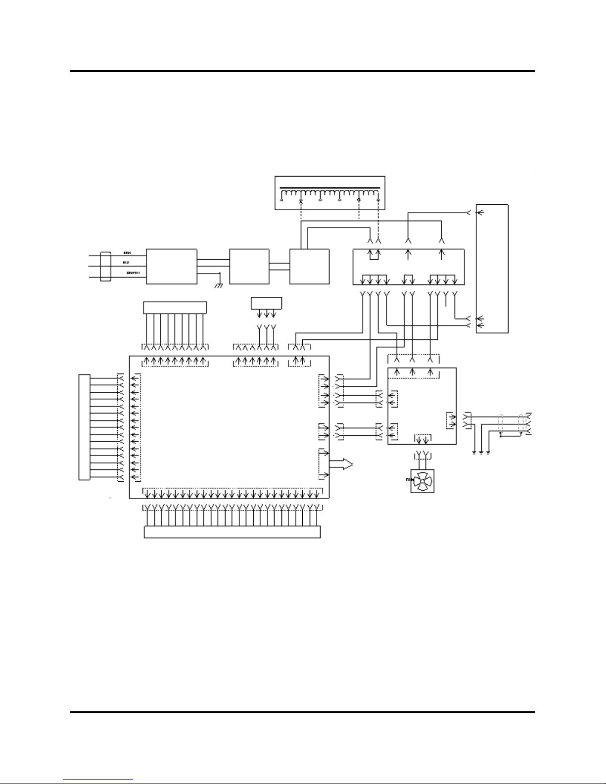
100-214-239 Rev. A 7-9
Interconnect Diagram
Digital Sonifier
7.4 Interconnect Diagram
User I/O
(15-pin)
Printer
(25-pin)
Ultrasonic
Power
Supply
Module
Variac
T1
Power
Switch
Line
Filter
IEC
Connector
Terminal Block
Digital Controls Board
RS-232
(9-pin)
Temperature
Probe Jack
Cordset
Display P5
Sonics J8
Variac/
Curr Loop
P4
P9 P3
P6
P1
P7
J7
J5
J1
J3
1
2
3
J4
23 5
(Export models only)
Converter
Cable
connection
 Loading...