

Page 1
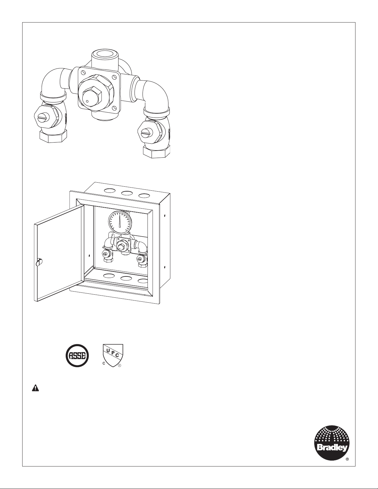
Installation
Thermostatic Mixing
Valve for Sinks/Faucets
Model S59-2007 (Valve Only)
Model S59-2007RE (Valve with
Recess-Mounted Enamel Cabinet)
Model S59-2007SE (Valve with
Surface-Mounted Enamel Cabinet)
Model S59-2007RS (Valve with
Recess-Mounted Enamel Cabinet)
Model S59-2007SS (Valve with
Surface-Mounted Enamel Cabinet)
Table of Contents
Supplies recommended for installation ...........................................2
Tools required for temperature adjustment .....................................2
Tools required for maintenance/troubleshooting .............................2
Optional Recessed / Surface Mounted Cabinet Dimensions ..........3
Install Optional Cabinet ...................................................................3
Installation Instructions ....................................................................4
Connect Supply Lines and Install Thermometer .............................4
Adjust Temperature with Water Running ......................................... 4
Test Unit ..........................................................................................4
Troubleshooting: Piston Disassembly and Cleaning .......................5
Troubleshooting Thermostatic Mixing Valve .................................... 6
Parts Breakdown .............................................................................7
ASSE 1017 and cUPC Certified
®
WARNING Installation and final temperature
adjustment are the responsibility
of the installer.
215-1297 Rev. L; ECN 17-08-009
© 2017 Bradley
Page 1 of 7 9/29/2017
Inlet Connections: 1/2" NPT
Outlet Connections: 1/2" NPT
Temperature Range: 95–115°F
Maximum Pressure: 125 PSIG
Inlet Temperature, Hot: 120°–200°F
Inlet Temperature, Cold: 33°–80°F
Minimum Temperature Differential
(from valve set point): 20°F
P.O. Box 309
Menomonee Falls, WI 53052 USA
800 BRADLEY (800 272 3539)
+1 262 251 6000
bradleycorp.com
Page 2

S59-2007 Series Installation
WARNING
Make sure that all water supply lines have been flushed and then completely turned off before beginning
installation. Debris in supply lines can cause valves to malfunction.
Failure to comply with proper installation and maintenance instructions could contribute to a valve failure
resulting in severe bodily injury including scalding, chilling and/or death depending upon system water
pressure changes and/or supply water temperature changes.
This thermostatic mixing valve is designed to be installed at or near the boiler or water heater. It is not
designed to compensate for system pressure fluctuations and should not be used where ASSE standard
1016, 1069 or 1070 devices are required. These valves should never be used to provide "anti-scald" or "antichill" service. This valve does not provide protection from pipe freezing.
Regular checking and cleaning of the valve's internal components and check stops is necessary for
maximum life and proper product function. Periodic inspection and yearly maintenance by a licensed
contractor is required. Corrosive water conditions and/or unauthorized adjustments or repairs could render
the valve ineffective for it's intended service. Frequency of cleaning and inspection depends upon local
water conditions.
Output temperature of the valve must be checked and adjusted at initial installation and on a quarterly basis.
IMPORTANT
Read this entire installation manual to ensure proper installation. When finished with the installation, file
this manual with the owner or maintenance department. Compliance and conformity to local codes and
ordinances is the responsibility of the installer.
Separate parts from packaging and make sure all parts are accounted for before discarding packaging
material. If any parts are missing, do not begin installation until you obtain the missing parts.
Consult local building and plumbing codes prior to installation. Should these codes differ from the
information in the manual, follow the local codes. Inquire with governing authorities for additional local
requirements.
Product warranties may be found under “Products” on our web site at bradleycorp.com.
Supplies recommended for installation
• lockable shut-off on the outlet if tempered water is supplied to a remote location
• lockable shut-off on the inlets/supplies
• unions on all connections to facilitate removal of valve
• (6) 3/8" wall anchors and fasteners for surface-mounted cabinet
• (4) 1/4" fasteners (and wall anchors, if necessary) for recess-mounted cabinet
Tools required for temperature adjustment
• 5/32" Allen wrench
Tools required for maintenance/troubleshooting
• 3/4" wrench (for acorn nut removal)
• 15/16" socket wrench and needle-nose pliers (for piston liner removal)
• 1/2" deep well socket wrench (for piston assembly’s upper seat removal)
2 9/29/2017 Bradley • 215-1297 Rev. L; ECN 17-09-008
Page 3
Installation S59-2007 Series
1
Recessed Cabinet:
1. Rough-in wall opening 11-1/2" W x 13" H.
2. Measure and mark the cabinet mounting hole locations at the
3. Insert the cabinet into the wall opening and secure into place
4. Insert valve into the bracket in the cabinet (right side of the
5. Continue with the valve installation procedure.
Install Optional Cabinet (If not installing cabinet, skip to Step 2)
Surface-Mounted Cabinet:
1. Measure and mark the cabinet mounting hole
locations at the dimensions shown. Install six 1/4" wall
dimensions shown. Install four 1/4" wall anchors, if required
(supplied by installer).
with four 1/4" wall fasteners (supplied by installer).
valve goes in first). Install the valve, elbows and stops onto the
inlet and outlet piping.
anchors (supplied by installer).
2. Position the cabinet onto the wall and secure into
place with six 1/4" wall fasteners (supplied by
installer).
3. Insert the valve into the bracket in the cabinet (right
side of the valve goes in first). Install the valve,
elbows and stops onto the inlet and outlet piping.
4. Continue with the valve installation procedure.
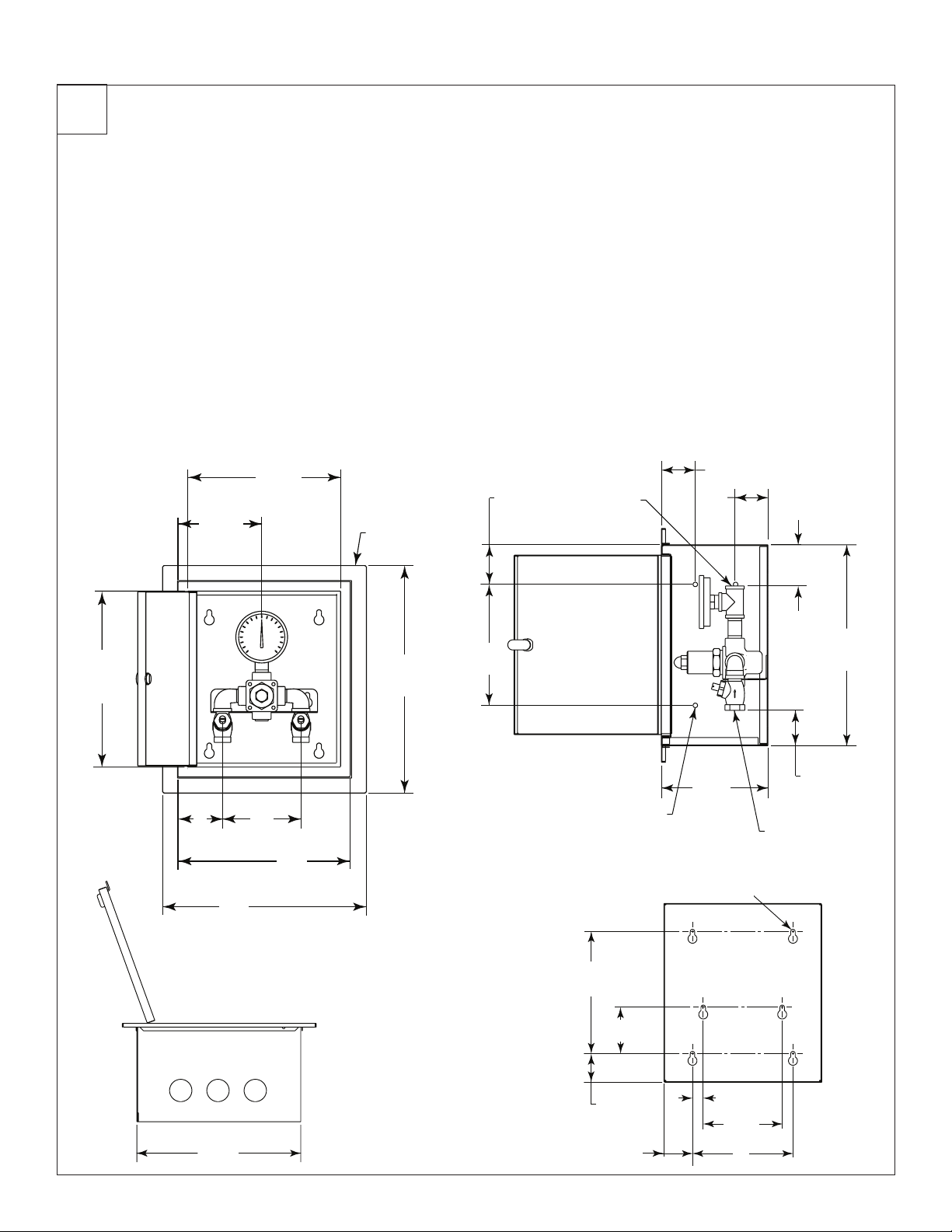
Optional Recessed / Surface Mounted Cabinet Dimensions
FRONT VIEW
5³⁄₈ "
(137)
9³⁄₄"
(248)
Door
Flange
SIDE VIEW
2¹⁄₂"
(64)
¹⁄₂" NPT
Outlet
2"
(51)
2"
(51)
2¹⁄₂"
(64)
(mm)
11¹⁄₄"
(286)
Door
13"
(330)
5"
(127)
3"
(76)
BOTTOM VIEW
11"
(279)
11"
(279)
BOX
7¹⁄₂"
14¹⁄₂"
(368)
(191)
MOUNTING HOLE LOCATIONS
⁹⁄₃₂ (6) Ø Holes
(4) Each Side (8)
Total
8¹⁄₂"
(216)
3¹⁄₄"
(83)
2"
(51)
(51)
12¹⁄₂"
(318)
¹⁄₂" NPT
Inlets
2¹⁄₄"
(57)
6¹⁄₂"
(165)
⁵⁄₁₆" Ø
(8)
(6) Holes
³⁄₄"
(19)
5¹⁄₂"
(140)
2"
7"
(178)
Bradley • 215-1297 Rev. L; ECN 17-09-008 9/29/2017 3
Page 4

S59-2007 Series Installation
2
3
Connect Supply Lines and Install Thermometer
Tempered Water
Flush the supply lines before
beginning installation.
When the stop/check valves are in the
closed position, the stem for the stop/
check will be 1/4" above the stem nut.
When the stop/check valves are in the
open position, the stem will extend out
approximately 1/2" (13mm) from the
stem nut.
Install Optional Thermometer using
pipe sealant or teflon tape.
Check for leaks by pressurizing
unit SLOWLY.
HOT
Acorn Nut
(to Fixture)
Adjust Temperature with Water Running
Stem
Stem Nut
COLD
4
Check the temperature when approximately
2-1/2 to 4 GPM water flow is reached
(equivalent to one shower).
This device must be checked for final temperature
and adjusted as necessary. The standard preset
factory temperature setting is 105°F (40.5°C). [the
range of the valve is 90°F – 120°F (32°C – 49°C)].
Consult proper medical and/or safety authorities
for the optimum temperature recommended for
your particular application.
Test Unit
DO NOT SKIP THIS STEP!!!
Acorn Nut
5/32" Allen Wrench
H
C
Shut the hot water supply off by closing hot water inlet valve or supply check valve. While the hot water supply is turned off, check
to make sure the cold water is reduced to .5 GPM or less. If the cold water is reduced properly, reopen the hot water supply.
Shut the cold water supply off by closing the cold water inlet valve or supply check valve. While the cold water supply is off, check
to make sure that the hot water flow has shut down. If hot water is shut down, reopen cold water supply.
4 9/29/2017 Bradley • 215-1297 Rev. L; ECN 17-09-008
Page 5

Installation S59-2007 Series
Troubleshooting: Piston Disassembly and Cleaning
Piston
Remove the valve's top cap and thermostat. Push
down on the piston with your finger (the piston
should move freely). If the movement is not as it
A
should be, the piston and liner assembly needs to
be cleaned.
Using a 15/16" socket wrench, loosen the piston/
liner assembly from the valve body and lift the
assembly out with a needle-nose pliers.
B
Disassemble the piston/liner assembly
components as shown (use a 1/2" deep well
socket to remove the upper seat). Clean with any
cleaner suitable for brass and stianless steel.
If cleaning with suitable cleaner is not sufficient to
remove debris, a 400-grit sand paper may be used
to polish and hone the piston and liner.
If, after a thorough cleaning, the piston does not
C
move freely, the piston/liner assembly must be
replaced. Contact your Bradley representative and
ask for Piston/Liner Kit (part number S65-205).
Top Cap
Thermostat
Retainer Ring
Retainer
Spring
Piston
Seal
Screw
Push Down
Then Release
Spring
Liner with
O-Ring
Bradley • 215-1297 Rev. L; ECN 17-09-008 9/29/2017 5
Page 6

S59-2007 Series Installation
Troubleshooting Thermostatic Mixing Valve
Before attempting to troubleshoot the valve or disassemble the
components, check for the following:
• Stop/check valves are fully open (the slotted stem
must be flush with the stop/check cap) and that all
inlet and outlet shut-off valves are open
• Hot and cold inlet pipes are connected properly, and
that there are no cross-connectio ns or leaking stop/
check valves
• Water heater output is at least 15° F above the set
temperature.
Be sure to close the appropriate shut-off valves prior to
disassembly of the valve and reopen the valves after inspection
and repair is complete.
Valve appearance may differ slightly.
Clean the valve
seats and other
components with a
small wire brush.
Stop/Check Valves
Problem Cause Solution
External leaks in the
system
No hot water flow
(cold water flow only)
Limited water flow The stop/check sections of the valve do not
Temperature
fluctuation or improper
Temperature
Either the NPT joints or the o-rings have
been damaged.
The thermostat has failed and,
subsequently, the safety shut-off has
engaged (the shut-off valve has closed on
either the inlets or outlet).
move freely.
Dirt and debris have collected on the check
screen or seat, limiting the movement of the
stop and checks.
Valve temperature is not properly set. See "Adjusting the Temperature" section.
Thermostat is slowly failing or not working
at all.
Inlet supply line to the mixing valve is being
shared by other pieces of equipment that
are used only periodically, such as laundry
appliances or washdown stations. It may
reduce the inlet pressure to the mixing valve
to less than 3 PSI. The supply line size may
not be large enough to supply both the valve
and the other appliances.
Replace the NPT joints and/or o-rings where necessary. For
replacement of o-rings, contact your Bradley representative
and ask for O-Ring/Seal Kit (S65-204).
Check the thermostat for proper operation:
1. At room temperature (80° or less), remove the top cap
and thermostat.
2. Place the thermostat into a small container filled
with 115° water. The pushrod should pop out of the
thermostat approximately 1/10".
If the thermostat pushrod does not pop out, the thermostat
must be replaced (it cannot be repaired). Contact your Bradley
representative and ask for Thermostat Kit (Part number S65-417).
Clean Stop and Check Valves:
Remove the stop and checks, clean the seat and reassemble
the valve. The stop/checks may also be disassembled and
cleaned. The components may be brushed with a small wire
brush to remove debris. If the stop/check valves need to be
replaced, contact your Bradley representative and ask for
Stop/Check Valve (part number S27-102 - Rough Brass,
S27-292A - Chrome).
Check Thermostat as described above, or replace.
Enlarge the supply line size, reconfigure the supply line or
regulate the supply usage.
6 9/29/2017 Bradley • 215-1297 Rev. L; ECN 17-09-008
Page 7

Installation S59-2007 Series
Parts Breakdown
Elbow
Valve Body
Stop/Check
4
5
6
8
9
10
11
7
15
18
16
2
3
Brass Plug
12
13
14
NOTICE! Some threaded joints are
17
19
assembled using high strength
thread lock and may require the use
of heat to loosen the connection.
Use caution to not damage o-rings
or other components.
Center Section Kit S65-306
Kit numbers for rough brass
finish and standard range
thermostat. Contact Bradley
for other configurations.
Piston and Liner Kit S65-205
Item Qty. Description
2 1 O-Ring
3 1 O-Ring
4 1 Liner
5 1 Spring
6 1 Screw
7 1 Seal
8 1 Piston
9 1 Spring
10 1 Retainer
11 1 Retainer Ring
Thermostat Kit S65-417
Item Qty. Description
5 1 Spring
6 1 Screw
7 1 Seal
8 1 Piston
9 1 Spring
10 1 Retainer
11 1 Retainer Ring
12 1 Thermostat
13 1 O-Ring
O-Ring and Seal Kit S65-204
Item Qty. Description
2 1 O-Ring
3 1 O-Ring
7 1 Seal
13 1 O-Ring
15 1 O-Ring
Item Qty. Description
2 1 O-Ring
3 1 O-Ring
4 1 Liner
5 1 Spring
6 1 Screw
7 1 Seal
8 1 Piston
9 1 Spring
10 1 Retainer
11 1 Retainer Ring
12 1 Thermostat
13 1 O-Ring
14 1 Retainer
15 1 O-Ring
16 1 Cap
17 1 Screw
18 1 Nametag
19 1 Acorn Nut
Bradley • 215-1297 Rev. L; ECN 17-09-008 9/29/2017 7
 Loading...