

Page 1
Installation
THIS
SIDE
UP
Packing List
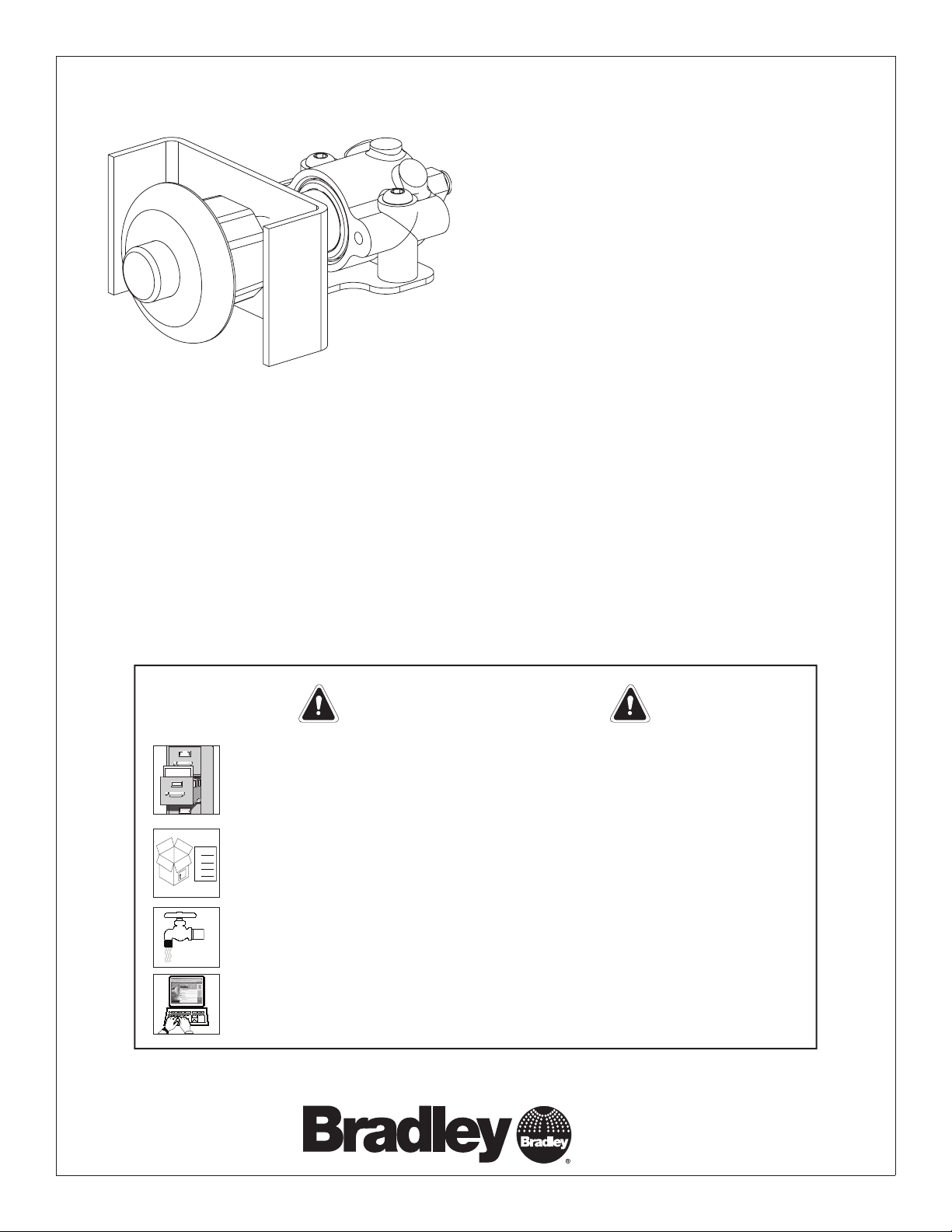
Standard push button shown
Installation
ASTM, ADTM, ASTS, ADTS
Piston-Operated Security Push Button
S45-1926 Piston Assembly
S45-1927A For Existing Escutcheon and Push Button
S45-1927B Includes Escutcheon and Hot Push Button
S45-1927C Includes Escutcheon and Cold Push Button
S45-1927D Includes Escutcheon and Blank Push Button
S45-1927E Includes Escutcheon and Ligature Resistant Push Button
Read this entire installation manual to ensure proper installation. When
finished with the installation, file this manual with the owner or maintenance
department. Compliance and conformity to local codes and ordinances is
the responsibility of the installer.
Separate parts from packaging and make sure all parts are accounted for
before discarding packaging material. If any parts are missing, do not begin
installation until you obtain the missing parts.
Make sure that all water supply lines have been flushed and then completely
turned off before beginning installation. Debris in supply lines can cause
valves to malfunction.
Product warranties may be found under “Products” on our web site at
bradleycorp.com.
215-1405 Rev. E ECN 13-10-005
© 2013 Bradley
Page 1 of 2 3/1/2013
IMPORTANT!
P.O. Box 309, Menomonee Falls, WI USA 53052-0309
PHONE 800.BRADLEY (800.272.3539)
FAX 262.251.5817 bradleycorp.com
Page 2
S45-1926, S45-1927A, S45-1927B, S45-1927C Installation
10
9
8
14
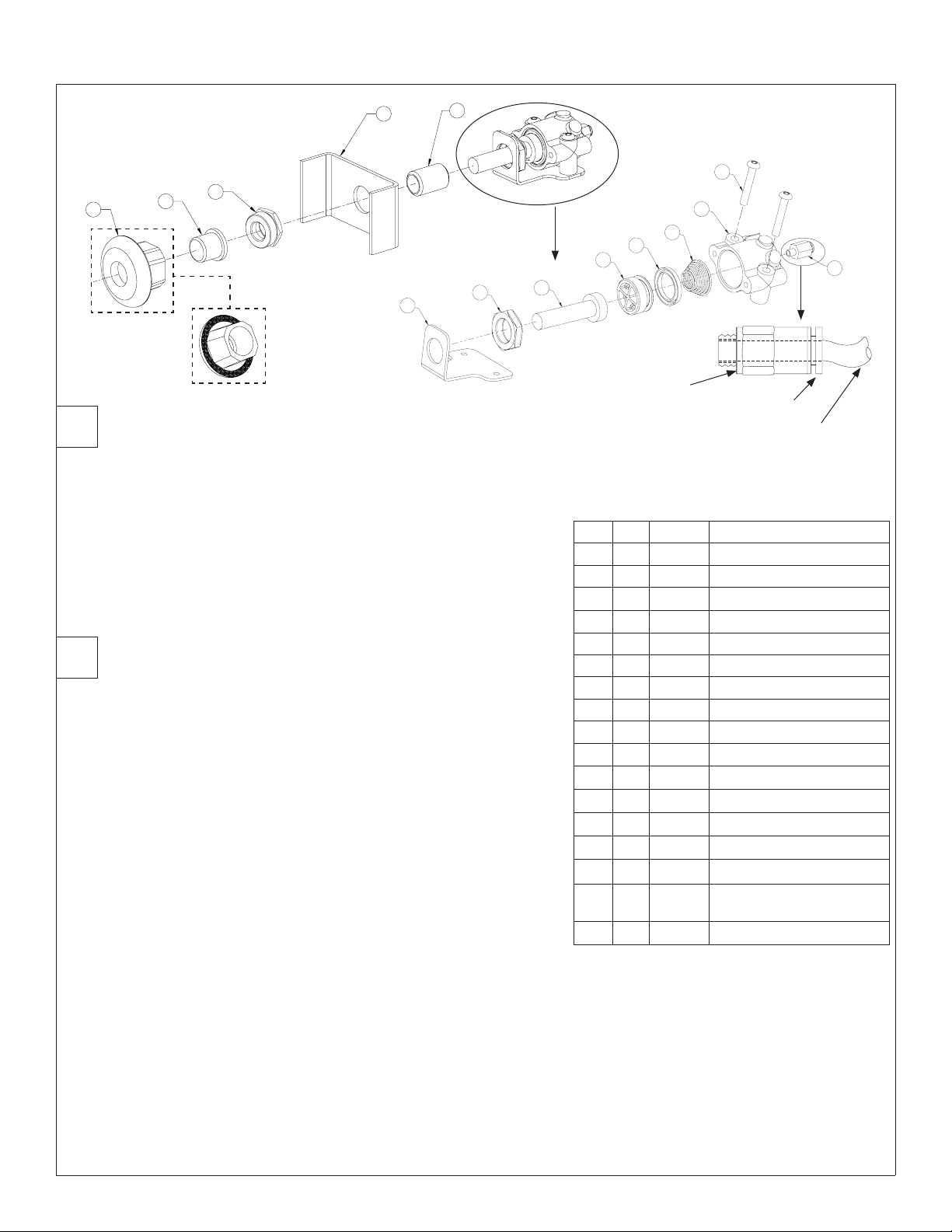
Remove Existing Assembly
1
13
12
11
1. Remove the air tube from the back of the existing assembly (Item 1) by
depressing the manual release button.
2. Loosen and unthread the brass nut (Item 8) from the push rod guide
(Item 10); the whole assembly will come apart.
3. Determine if the existing escutcheon (Item 14) and push button (Item 13)
are useable or if new parts from the appropriate kit will be used.
Install New Assembly
2
1. Apply 100% silicone caulk to escutcheon (item 14) backside prior to
installation to ensure a water tight seal. Wipe excess caulk from front
side of escutcheon and panel.
2. Insert the new push button (Item 13) into the escutcheon (Item 14).
3. Thread the bushing (Item 12) into the escutcheon. Tighten to secure
the parts.
4. Thread the push rod guide (Item 10) into the bushing (Item 12).
5. Tighten to secure the parts, taking care not to damage the threads on
the push rod guide.
6. Insert the assembled escutcheon, push button, and push rod guide into
the hole in the existing mounting plate.
7. Place the mounting bracket (Item 11) over the protruding escutcheon
assembly.
8. Place the push rod cap (Item 7) (from the piston assembly) into the
push rod guide (Item 10).
9. Thread the brass nut (Item 8) onto the push rod guide (Item 10).
10. Align the parts per the illustration and tighten the brass nut to complete
the assembly.
11. Insert the air hose removed in Step 1 into the tube connector (Item 1).
2
3
4
5
6
7
Tube Stop
Manual Release Button
1/8" Air Valve Tubing
Parts List
Item Qty. Part No. Description
1 1 169-890 Tube Connector #10-32 x 1/8”
2 2 160-165 B hd Socket Screw
3
4 1 135-065 Spring
5 1 125-099 U-Cup
6 1 119-227 Molded Piston
7 1 136-026 Pushrod Cap
8 1 110-057 Brass Nut 3/8" NPT
9 3 140-897 Actuator Bracket
10 1 179-094 Pushrod Guide
11 1 140-676 Mounting Bracket
12 1 153-348 Bushing
13 1 128-062 Hot Push Button
13 1 128-063 Cold Push Button
13 1 128-144 Blank Push Button
13 1
14 1 150-099 Escutcheon
118-279 Molded Actuator Body
1
128-185 Ligature Resistant Push
Button
S45-1926: Piston assembly contains items 1–9
and comes pre-assembled.
S45-1927A: Push Button assembly utilizes
existing push button and escutcheon. Includes
items 1–12.
The following Push Button assemblies include
items 1–14:
S45-1927B (Hot Push Button only)
S45-1927C (Cold Push Button only)
S45-1927D (Blank Push Button only)
S45-1927E (Ligature Resistant Push Button only)
1
2 3/1/2013 Bradley • 215-1405 Rev. E; ECN 13-10-005
 Loading...