

Page 1
Installation
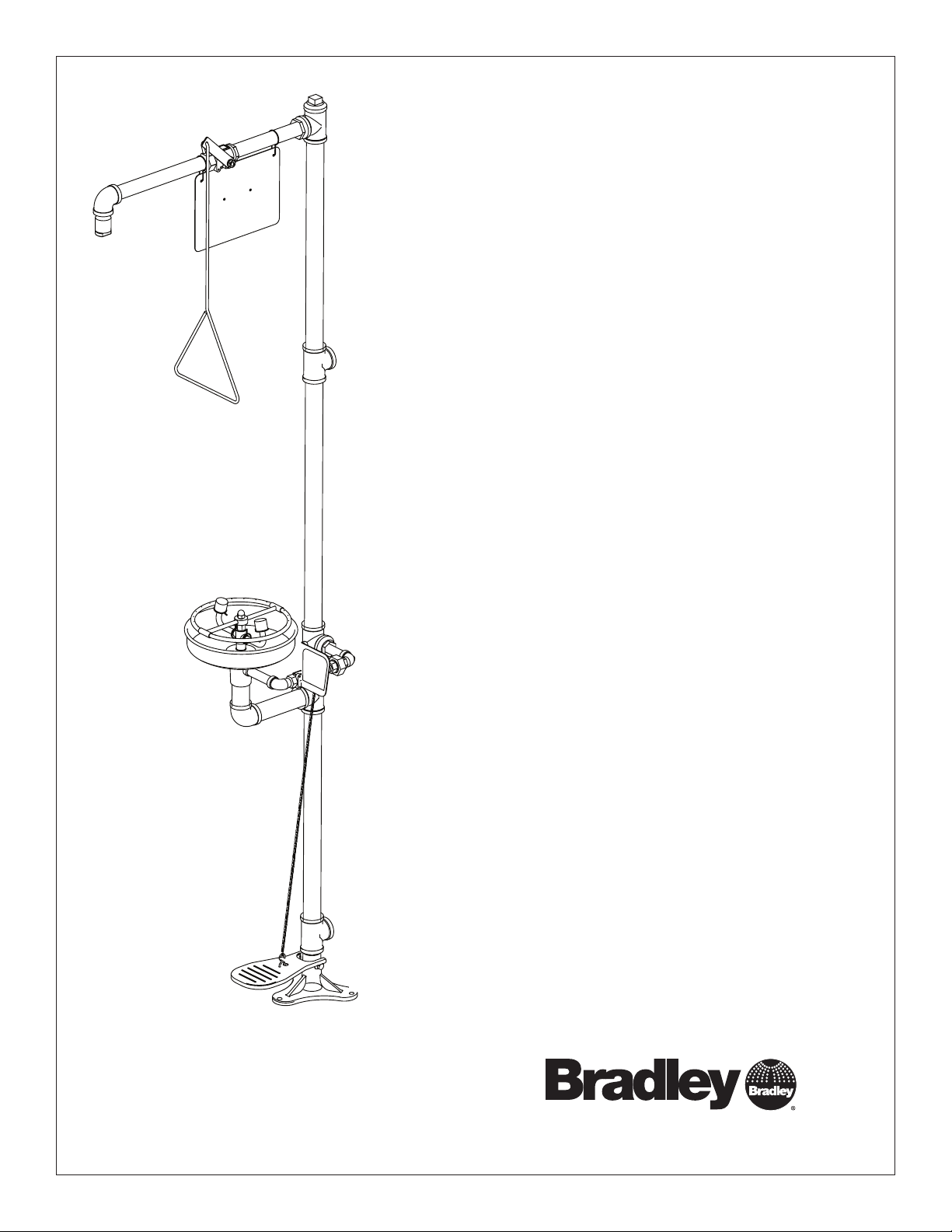
S19-310SS
Combination Drench Shower
and Eyewash
Combiné douche oculaire
Combinación de ducha de aspersión
y lavaojos
Table of Contents
Pre-Installation Information........................ 2
Installation Instructions........................... 3
Assembly of Components......................... 4
Parts List...................................... 5
Table des matières
Avant l’installation............................... 6
Instructions d’installation ......................... 7
Assemblage des composantes..................... 8
Liste des pièces ................................ 9
Contenido
Información previa a la instalación................. 10
Instrucciones de instalación ...................... 11
Armado de los componentes ..................... 12
Lista de piezas ................................ 13
215-533 Rev. Y; ECN 12-05-033
© 2013 Bradley
Page 1 of 13 3/14/2013
P.O. Box 309, Menomonee Falls, WI USA 53052-0309
PHONE 800.BRADLEY (800.272.3539) FAX 262.251.5817
bradleycorp.com
Page 2
S19-310SS Installation
IMPORTANT
Read this installation manual completely to ensure proper installation, then file it with the
Installation
owner or maintenance department. Compliance and conformity to drain requirements and
other local codes and ordinances is the responsibility of the installer.
Packing List
•
•
•
THIS
SIDE
•
UP
Separate parts from packaging and make sure all parts are accounted for before discarding
any packaging material. If any parts are missing, do not begin installation until you obtain
the missing parts.
Flush the water supply lines before beginning installation and after installation is complete.
Test the unit for leaks and adequate water flow. Main water supply to the eyewash should be
"ON" at all times. Provisions shall be made to prevent unauthorized shutoff.
The ANSI Z358.1 standard requires an uninterrupted supply of flushing fluid. Bradley
plumbed emergency fixtures require a minimum of 30 PSI (0.21 MPa) flowing pressure.
Flushing fluid should be tepid per ANSI Z358.1.
R
WI 53051
alls,
below.
PRÜFEN.
bestätigt
t melden.
y.
a pas fait
HENTLICH ZU
WEEK
WÖC
P.O. Box 309, Menomonee F
DAIRE
Testbetrieb prüfen,
he Störung sofor
alves chaque semaine et
e(s) each week and sign
UNIT EACH
Signed
e chose qui ne v
Signed
Date Signed
y malfunctions immediatel
hentlich im
TEST THIS
hrift. Jeglic
Date
DIESES GERÄT 1ST
ESSAI HEBDOMA
Date
Test-operate valv
Report an
Ventil(e) wöc
t immédiatement.
durch Untersc
Signed
Test le fonctionnement des v
Unterschrift
signe en bas. S'il y à quelqu
Signe
un rappor
Date
Datum
Date
The inspection and testing results of this equipment should be recorded weekly to verify
proper operation. This equipment should be inspected annually to ensure compliance with
ANSI Z358.1.
Workers who may come in contact with potentially hazardous materials should be trained
regarding the placement and proper operation of emergency equipment per ANSI Z358.1.
P.O. BOX 309, MENOMONEE FALLS, WI 53052-0309 USA
TEL: 1-800-BRADLEY FAX: (262-251-5817)
http://www.bradleycorp.com
114-051
For questions regarding the operation or installation of this product, visit www.bradleycorp.
com or call 1-800-BRADLEY.
Product warranties and service parts information may also be found under "Products" on
our web site at www.bradleycorp.com.
2
3/14/2013 Bradley • 215-533 Rev. Y; ECN 12-05-033
Page 3
Installation S19-310SS
Installation
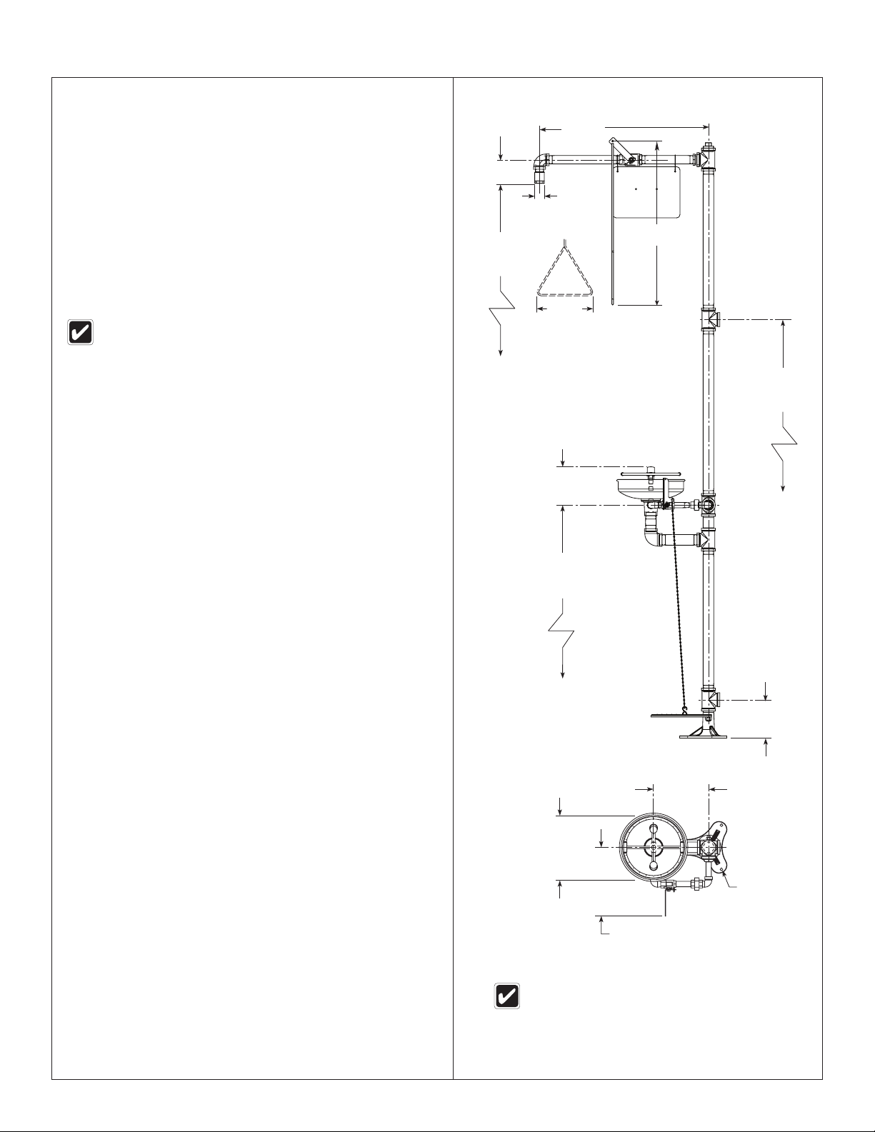
26³⁄₈"
Supplies Required:
• (3) ³⁄₈" floor anchors and bolts
• Pipe sealant
• Piping to 1¼" NPT water supply inlet and 1¼" NPT
drain outlet on unit
• Adequate supply pipe supports
• Minimum 4" (102mm) drain to accommodate 30
gallons (115 liters) per minute discharge for shower
waste
• OPTIONAL: sign-mounting hardware
Local codes may require the installation of a backflow
prevention valve to complete proper installation. Compliance
with local codes is the responsibility of the installer. Valve
must be tested annually to verify that it is functioning
properly. Backflow prevention valves are not included
with the fixture and may be supplied by the contractor or
purchased from Bradley Corporation.
Step 1: Secure base to floor
1. Install three suitable anchors (supplied by installer) for ³⁄₈"
bolts in the floor.
2. Bolt the base to the floor anchors using ³⁄₈" bolts (supplied
by installer).
3¾"
(95mm)
86¾"
(2203mm)
to Floor
(670mm)
Ø 1½"
(38mm)
25½"
(648mm)
9"
(229mm)
66"
(1676mm)
to Floor
152mm
(6")
Step 2: Assemble components
1. Assemble the remaining unit components as shown on
page 4.
• Apply pipe sealant (by installer) to all male-threaded
pipe joints.
• Use the rubber grip pad provided or a strap wrench
around pipes when tightening to prevent marring. Place
the grip pad on the pipe, then put the wrench over the
grip pad and turn the pipe with the wrench.
• When connecting the steel chain, first connect the
chain to the "S" hook on the foot treadle. Then, with the
foot treadle raised up, straighten the chain and connect
a link to the "S" hook on the valve handle. Make sure
the chain is pulled tight and opens valve completely.
The length of chain will vary from unit to unit.
Notice! Once the chain length is determined and confirmed
to operate the valve correctly, use a pliers to close
all s-hook openings to maintain this setting.
• The bottom edge of the showerhead should be 86¾"
(2203mm) from the floor.
Step 3: Connect water supply
IMPORTANT! Do not rely on Bradley’s Combination
Unit to support supply piping.
1. Connect water supply piping to 1¼" NPT inlet on unit (piping
by installer). Provide adequate supports (by installer) for
supply pipe using pipe hangers or other means.
2. Connect drain piping to 1¼" NPT drain outlet on unit (piping
by installer).
3. Hang the safety sign from the unit with the curtain hooks
provided (or mount it to the wall using sign-mounting
hardware by installer).
36³⁄₈"
(924mm)
Top View From Bowl
9"
(229mm)
Ø 10¾"
(273mm)
10½"
(267mm)
All dimensions assume standard thread
engagement. Variations in manufacturing allow
for +/- 1⁄8" (3mm) per threaded joint. To find
the tolerance of a dimension, add the number
of thread joints in between a dimension and
multiply it by 1⁄8" (3mm).
6"
(152mm)
Ø 9" (229mm)
Flange with (3)
Ø ³⁄₈" (10mm)
Holes on Ø 8"
(203mm) Bolt
Circle
Bradley • 215-533 Rev. Y; ECN 12-05-033 3/14/2013
3
Page 4
S19-310SS Installation
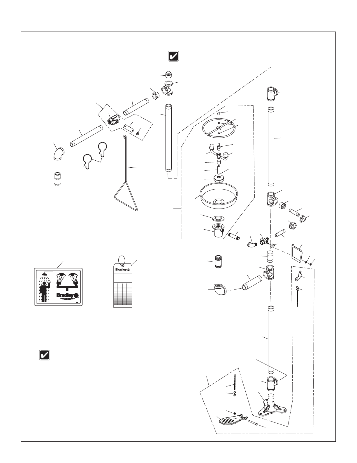
Assembly of Components
If tee (Item 2) is used as a supply
inlet, use plug (Item 6) on tee (Item 2)
6
2
Optional 1¼" NPT
Supply Inlet (best for
rigid support)
25.7
25.6
25.5
25.4
2
1¼" NPT
Supply Inlet
25.12
25.11
25.10
5
25.9
25.8
Flow
control this
end
2
13
12
11
7
9
9.1
8
3
9.2
9.11
10
14
27
P.O. BOX 309, MENOMONEE FALLS, WI 53052-0309 USA
TEL: 1-800-BRADLEY FAX: (262-251-5817)
http://www.bradleycorp.com
P.O. Box 309, Menomonee Falls, WI 53051
TEST THIS UNIT EACH WEEK
DIESES GERÄT 1ST WÖCHENTLICH ZU PRÜFEN.
ESSAI HEBDOMADAIRE
Test-operate valve(s) each week and sign below.
Report any malfunctions immediately.
Ventil(e) wöchentlich im Testbetrieb prüfen, bestätigt
durch Unterschrift. Jegliche Störung sofort melden.
Test le fonctionnement des valves chaque semaine et
signe en bas. S'il y à quelque chose qui ne va pas fait
un rapport immédiatement.
Date
Signed
Datum
Unterschrift
Date
Signe
114-052
Date Signed
Date
Date
28
R
Signed
Signed
Items 9.1–9.2 come preassembled as Item 9.
Items 25.1–25.12 come preassembled as Item 25.
25
25.3
25.2
25.1
24
23
22
17
19
1¼" NPT
Drain Outlet
15
16
17
18
20
16
31
4
21
30
20.1
2
26.6
26.1
3
26
2
26.2
26.1
1
26.5
26.3
26.4
4
3/14/2013 Bradley • 215-533 Rev. Y; ECN 12-05-033
Page 5

Installation S19-310SS
Parts List
Item Part No. Qty. Description
1 131-062 1 Base
2 269-237 5 Pipe Tee 1¼" NPT
3 113-583 2 Pipe 1¼" NPT x 22½"
4 S06-188 1 Plugged Nipple
5 113-584 1 Pipe 1¼" NPT x 26½"
6 269-238 1 Pipe Plug 1-1/4" NPT
7 269-236 1 Reduc’g Bushing 1¼" to 1"
NPT
8 113-006NX 1 Pipe 1" NPT x 9"
9 S30-061 1 Stay-Open Ball Valve 1" NPT
9.1 S27-276 1 1" Ball Valve with Jam Nut
9.11 161-079 1 Jam Nut only
9.2 128-142 1 Handle
10 151-001 2 Curtain Hook
11 113-006MN 1 Pipe 1" NPT x 12"
12 169-1074 1 90º Elbow 1" NPT
13 S24-191 1 Showerhead Assembly
14 128-156A 1 Pull Rod - 25½" Long
15 269-239 1 Reduc’g Bushing 1¼" to 1"
NPT
16 113-965 2 Pipe ½" NPT x 3½"
17 269-241 2 Elbow ½" NPT
18 269-240 1 Union ½" NPT
19 113-582 1 Pipe 1¼" NPT x 6½"
20 S27-328 1 ½" Ball Valve with Nut
20.1 110-248 1 Nut 316 Stainless Steel
21 S08-336 1 Handle Assembly
22 113-866 1 Pipe ½" NPT x 4"
23 269-242 1 90° Pipe Elbow 1¼" NPT
Item Part No. Qty. Description
24 113-579 1 Pipe Nipple 1¼" NPT x 3"
25 S90-317 1 Stainless Steel Spray Ring
Assy.
25.1 111-049 1 Inlet-Drain Fitting
25.2 124-028 1 Center Seal Gasket
25.3 187-053 1 Stainless Steel Bowl
25.4 173-009 1 Cup Strainer
25.5 S21-074 1 Supply Pipe
25.6 113-1159 1 Spacer, Drain
25.7 S05-131 1 Eyewash Yoke
25.8 107-371 2 Dust Cover
25.9 269-912 1 Swivel Stem
25.10 124-055 2 Quad Ring
25.11 S57-148 1 Spray Ring Assembly
25.12 110-209 1 Acorn Nut
26 S45-1314SS 1 Stainless Steel Foot Treadle Kit
26.1 269-646 2 "S" Hook
26.2 134-009A 1 Stainless Steel Chain
26.3 181-014 1 Stainless Steel Foot Pedal
26.4 160-401 1 Screw
26.5 161-164 1
26.6 128-136 1 Handle
27 114-052 1 Safety Sign
28 204-421 1 Emergency Inspection Tag
29 269-915 1 Grip Pad (not shown)
30 142-002DA 1 Washer
31 153-372R 1 Adapter
Nut, ³⁄₈"-16 Stainless Steel
Centerlock
Prepack S45-1788 includes Items 25.9, 25.10, 25.11, 25.12
Prepack S30-109 includes items 20, 21, 30, 31
For proper handle and ball valve kits, refer to instruction sheet 215-1774.
Bradley • 215-533 Rev. Y; ECN 12-05-033 3/14/2013
5
Page 6

S19-310SS Installation
IMPORTANT
Installation
R
WI 53051
alls,
PRÜFEN.
HENTLICH ZU
WEEK
WÖC
P.O. Box 309, Menomonee F
DAIRE
Testbetrieb prüfen,
e(s) each week and sign
UNIT EACH
y malfunctions immediatel
hentlich im
TEST THIS
hrift. Jeglic
DIESES GERÄT 1ST
ESSAI HEBDOMA
Test-operate valv
Report an
Ventil(e) wöc
t immédiatement.
durch Untersc
Test le fonctionnement des v
signe en bas. S'il y à quelqu
un rappor
Date
Datum
Date
Lire ce manuel d’installation dans son intégralité pour garantir une installation appropriée.
Une fois celle-ci terminée, classer ce manuel auprès du service à la clientèle ou d’entretien.
L’installateur est responsable de la conformité de l’installation aux codes pour des drain et
codes et règlements en vigueur.
Packing List
•
•
•
THIS
SIDE
•
UP
Assurez-vous que toutes les pièces sont incluses dans l’emballage et qu’il n’en manque
aucune avant de jeter l’emballage. Ne commencez pas l’assemblage avant de recevoir les
pièces manquantes.
Rincez la conduite d’alimentation avant et apres l’installation. Assurez-vous que le débit
d’eau est adéquat et qu’il n’y a pas de fuites. L’alimentation principale en eau doit être
toujours OUVERTE. On devra prévoir des dispositions pour empêcher tout arrêt non
autorisé.
La norme ANSI Z358.1 prévoit une alimentation ininterrompue du liquide de rinçage. Les
appareils d’urgence Bradley raccordés au réseau nécessitent une pression d’écoulement
d’au moins 30 PSI (0,21 MPa). Selon ANSI Z358.1, le liquide de rinçage doit être tiède.
Inspectez et testez cet équipement une fois par semaine pour en assurer le bon
below.
bestätigt
t melden.
y.
a pas fait
he Störung sofor
alves chaque semaine et
Signed
e chose qui ne v
Signed
Date Signed
Date
Date
Signed
Unterschrift
Signe
fonctionement. Notez les dates d’inspection. Ce matériel doit être inspecté une fois par an
pour assurer sa conformité à la norme ANSI Z358.1.
Les ouvriers susceptibles d’entrer en contact avec des matières potentiellement
dangereuses doivent recevoir une formation sur la mise en place et le bon fonctionnement
du matériel d’urgence conformément à la norme ANSI Z358.1.
P.O. BOX 309, MENOMONEE FALLS, WI 53052-0309 USA
TEL: 1-800-BRADLEY FAX: (262-251-5817)
http://www.bradleycorp.com
114-051
Pour toute question concernant le fonctionnement ou l’installation de ce produit, consulter le
site www.bradleycorp.com ou appeler le 1-800-BRADLEY.
Les garanties de produits figurent sous la rubrique " Informations techniques " sur notre site
Internet à www.bradleycorp.com.
6
3/14/2013 Bradley • 215-533 Rev. Y; ECN 12-05-033
Page 7

Installation S19-310SS
Installation
Equipements nécessaires :
• 3 ancrages au sol et boulons de ³⁄₈"
• Produit d’étanchéité pour tuyaux
• Tuyau d’alimentation pour branchement au raccord NPT de 1¼"
d’arrivée d’eau de l’appareil
• Supports adéquats pour la tuyauterie d’alimentation
• Tuyau de vidange de 1¼" NPT pour la douche oculaire
• Un renvoi de 4" (102mm) minimum pour la douche d’urgence
assurant une capacité de vidange de 30 gal/mn (115 l/mn)
• Quincaillerie pour l’installation de l’enseigne
Les codes locaux peuvent exiger l’ installation d’une soupape de
prévention d’écoulement de retour pour réaliser une installation
appropriée. L’installateur est responsable de la conformité aux
codes locaux. La soupape doit être testée une fois par an pour
vérifier qu’elle fonctionne correctement. Les soupapes de prévention
d’écoulement de retour ne sont pas fournies avec l’appareil et
peuvent être fournies par l’entrepreneur ou achetées auprès de
Bradley Corporation.
Étape 1: Fixation de la bride au sol
1. Installez 3 ancrages (non fournis) pour vis de ³⁄₈" dans le sol.
2. Vissez la bride dans les ancrages à l’aide des vis de ³⁄₈" (non fournies).
3¾"
(95mm)
86¾"
(2203mm)
to Floor
26³⁄₈"
(670mm)
Ø 1½"
(38mm)
25½"
(648mm)
9"
(229mm)
66"
(1676mm)
du sol
152mm
(6")
Étape 2 : Assemblage des composantes
1. Assemblez d’abord la douche d’urgence, puis la douche oculaire (voir
page 8).
• Mettez du produit d’étanchéité (non fourni) sur tous les filetages
mâles.
• Utilisez des tampons autour des tuyaux pour ne pas les
endommager lors du serrage. Placez le tampon sur le tuyau
puis la clé par dessus. Laissez le tampon en place, et tournez
le tuyau avec la clé.
• Pour relier la chaîne en acier il faut d’abord la fixer au crochet
en S de la pédale. Ensuite, la pédale étant relevée, tendez la
chaîne et accrochez un maillon au crochet en S situé sur la
manette du robinet. Vérifier que la chaîne est tendue et ouvre la
complètement la vanne. La longueur de chaîne varie en fonction
du modèle.
AVIS ! Après avoir déterminé la longueur de chaîne et vérifié qu’elle
actionne correctement la vanne, utiliser une pince pour fermer
tous les crochets en S ouverts afin de maintenir ce réglage.
• Le bord inférieur de la pomme de la douche d’urgence doit se
trouver à 86¾" (2203mm) du sol.
Étape 3 : Raccordement de l’alimentation
en eau
IMPORTANT! Ne pas utiliser la douche d’urgence Bradley pour
supporter la tuyauterie d’alimentation.
1. Raccordez l’alimentation en eau sur l’orifice d’alimentation de 1¼" NPT
de la douche d’urgence (tuyauterie non fournie). Prévoyez des supports
adéquats (non fournis) pour la tuyauterie d’alimentation.
2. Raccordez le tuyau de vidange sur l’orifice de vidange de 1¼" NPT de
la douche d’urgence (tuyauterie non fournie).
3. Installer l’enseigne de sécurité au mur à l’aide de la quincaillerie
d’installation (fournie par l’installateur).
36³⁄₈"
(924mm)
Vue supérieure de cuvette
9"
(229mm)
Ø 10¾"
(273mm)
10½"
(267mm)
Toutes les dimensions supposent un
engagement de filetage standard. Les
variations de fabrication prévoient +/- 3,1
mm (1⁄8") par joint fileté. Pour trouver
la tolérance d’une dimension, ajouter
le nombre de joints filetés entre une
dimension et le multiplier par 3,1 mm (1⁄8").
6"
(152mm)
Bride Ø 9"
(229mm) avec
(3) trois trous
de Ø ³⁄₈" (10mm)
sur un de Ø 8"
(203mm)
Bradley • 215-533 Rev. Y; ECN 12-05-033 3/14/2013
7
Page 8

S19-310SS Installation
Assembage des composantes
Si le raccord en té (point nº 2) est utilisé comme orifice
d’admission, utiliser le bouchon (point nº 6) au point nº 2.
6
2
Alimentation
1¼" NPT
25.7
25.6
25.5
25.4
2
Alimentation
1¼" NPT
25.12
25.11
25.10
5
25.9
25.8
Contrôle
du débit,
ce bout
2
13
12
11
7
9
9.1
8
3
9.2
9.11
10
14
27
P.O. BOX 309, MENOMONEE FALLS, WI 53052-0309 USA
TEL: 1-800-BRADLEY FAX: (262-251-5817)
http://www.bradleycorp.com
P.O. Box 309, Menomonee Falls, WI 53051
TEST THIS UNIT EACH WEEK
DIESES GERÄT 1ST WÖCHENTLICH ZU PRÜFEN.
ESSAI HEBDOMADAIRE
Test-operate valve(s) each week and sign below.
Report any malfunctions immediately.
Ventil(e) wöchentlich im Testbetrieb prüfen, bestätigt
durch Unterschrift. Jegliche Störung sofort melden.
Test le fonctionnement des valves chaque semaine et
signe en bas. S'il y à quelque chose qui ne va pas fait
un rapport immédiatement.
Date
Signed
Datum
Unterschrift
Date
Signe
114-052
Date Signed
Date
Date
28
R
Signed
Signed
Les articles 9.1–9.2 sont préassemblés tel que 9.
Les articles 25.1–25.12 sont préassemblés tel que 25.
25
25.3
25.2
25.1
24
23
22
17
19
Orifice de vidange
1¼" NPT
15
16
17
18
20
16
31
4
21
30
20.1
2
26.6
26.1
3
26
2
26.2
26.1
1
26.5
26.3
26.4
8
3/14/2013 Bradley • 215-533 Rev. Y; ECN 12-05-033
Page 9

Installation S19-310SS
Liste des piéces
Piéce Réf Qté Description
1 131-062 1 Bride
2 269-237 5 Té 1¼" NPT
3 113-583 2 Tuyau 1¼" NPT x 22½"
4 S06-188 1 Mamelon obturé
5 113-584 1 Tuyau 1¼" NPT x 26½"
6 269-238 1 Bouchon 1¼" NPT
7 269-236 1 Réducteur 1¼" > 1" NPT
8 113-006NX 1 Tuyau 1" NPT x 9"
9 S30-061 1 Robinet de 1" à tournant
sphérique
9.1 S27-276 1 Robinet 1" (avec écrou)
9.11 161-079 1 Écrou (seulement)
9.2 128-142 1 Manette
10 151-001 2 Crochet
11 113-006MN 1 Tuyau 1" NPT x 12"
12 169-1074 1 Coude 90° de 1" NPT
13 S24-191 1 Tête de douche
14 128-156A 1 Tige - 25½"
15 269-239 1 Réducteur 1¼" > ½" NPT
16 113-965 2 Tuyau ½" NPT x 3½"
17 269-241 2 Coude ½" NPT
18 269-240 1 Union ½" NPT
19 113-582 1 Tuyau 1¼" NPT x 6½"
20 S27-328 1 Robinet ½" (avec écrou)
20.1 110-248 1 Écrou en acier inoxydable 316
21 S08-336 1 Assemblage de manette
22 113-866 1 Tuyau ½" NPT x 4"
23 269-242 1 Coude 90° 1¼" NPT
24 113-579 1 Raccord 1¼" NPT x 3"
Piéce Réf Qté Description
25 S90-317 1 Disperseur Annulaire
25.1 111-049 1 Raccordement d’entrée du
drain
25.2 124-028 1 Joint d’etanchéité
25.3 187-053 1 Assemblage du récepteur inox
25.4 173-009 1 Filtre à tamis
25.5 S21-074 1 Alimentation acier inox
25.6 113-1159 1 Entretoise
25.7 S05-131 1 Assemblage de cadre
25.8 107-371 2 Couvercle anti-poussières
25.9 269-912 1 Pivot
25.10 124-055 2 Rondelle
25.11 S57-148 1 Diffuseur Annulaire
25.12 110-209 1 Écrou Borgne
26 S45-1314SS 1 Trousse pédale en acier
inoxydable
26.1 269-646 2 Crochet en S
26.2 134-009A 1 Chaîne en acier inoxydable
26.3 181-014 1 Pédale en acier inoxydable
26.4 160-401 1 Vis
26.5 161-164 1
26.6 128-136 1 Manette
27 114-052 1 Enseigne de sécurité
28 204-421 1 Etiquette d’inspection
29 269-915 1 Tampon anti dérapant (non
30 142-002DA 1 Rondelle
31 153-372R 1 Adaptateur
Écrou Centerlock de ³⁄₈"-16 en
acier inoxydable
montré)
Paquet S45-1788 comprend les éléments 25.9, 25.10, 25.11, 25.12
Paquet S30-109 comprend les éléments 20, 21, 30, 31
Voir les trousses de poignée et de robinet à tournant sphérique correctes dans la fiche d’instruction 215-1774.
Bradley • 215-533 Rev. Y; ECN 12-05-033 3/14/2013
9
Page 10

S19-310SS Installation
IMPORTANTE
Installation
R
WI 53051
alls,
HENTLICH ZU
WEEK
WÖC
P.O. Box 309, Menomonee F
DAIRE
e(s) each week and sign
UNIT EACH
y malfunctions immediatel
hentlich im
TEST THIS
hrift. Jeglic
DIESES GERÄT 1ST
ESSAI HEBDOMA
Test-operate valv
Report an
Ventil(e) wöc
durch Untersc
Test le fonctionnement des v
signe en bas. S'il y à quelqu
un rappor
Date
114-051
PRÜFEN.
Testbetrieb prüfen,
t immédiatement.
Datum
Date
below.
y.
he Störung sofor
alves chaque semaine et
e chose qui ne v
Signed
Unterschrift
Signe
THIS
SIDE
UP
bestätigt
t melden.
a pas fait
Signed
Signed
Date Signed
Date
Date
P.O. BOX 309, MENOMONEE FALLS, WI 53052-0309 USA
TEL: 1-800-BRADLEY FAX: (262-251-5817)
http://www.bradleycorp.com
Packing List
•
•
•
•
Lea en su totalidad este manual de instalación para garantizar una instalación adecuada.
Una vez que termine la instalación, entregue este manual al propietario o al Departamento
de Mantenimiento. Es responsabilidad de quien instale el equipo cumplir con los códigos
para desagüe y otra códigos y ordenanzas locales.
Separar todas las piezas del material de embalaje y asegurarse que todas las piezas estén
incluídas antes de desechar cualquier material de embalaje. Si faltase alguna pieza, no
intentar instalar la unidad combinada Bradley hasta obtener las piezas faltantes.
Aclarar el conducto del suministro de agua antes y después de la instalación. Verificar que
no haya fugas y que el flujo de agua sea adecuado. El suministro principal de agua a la
unidad debe estar siempre en posición "ON" (abierto). Se deben tomar medidas a fin de
evitar el corte no autorizado del suministro.
La norma ANSI Z358.1 exige un suministro ininterrumpido de líquido de limpieza. Los
equipos de emergencia con tuberías de Bradley requieren una presión de flujo mínima de
0,21 MPa (30 PSI). El líquido de limpieza debe estar tibio en conformidad con la norma ANSI
Z358.1.
Este equipo se debe inspeccionar, probar y anotar semanalmente para mantener un
funcionamiento adecuado. Se debe revisar este equipo anualmente para asegurarse de que
cumpla con la norma ANSI Z358.1.
Los trabajadores que puedan tener contacto con materiales potencialmente peligrosos
deben recibir capacitación sobre la ubicación y operación adecuada de los equipos de
emergencia en conformidad con la norma ANSI Z358.1.
Para consultas sobre la operación o instalación de este producto, visite www.bradleycorp.
com o llame al 1-800-BRADLEY.
Las garantías del producto se pueden encontrar e n "Información del producto" o en nuestro
sitio Web, www.bradleycorp.com.
10
3/14/2013 Bradley • 215-533 Rev. Y; ECN 12-05-033
Page 11

Installation S19-310SS
Instalación
Materiales necesarios:
• (3) anclas para el piso y pernos de ³⁄₈"
• Sellador de tubería
• Tubería a la entrada de suministro de agua NPT de 1¼"
• Apoyos de tubería de suministro adecuados
• Tubería a la salida del desagüe NPT a 1¼" para el mecanismo del
lavado de los ojos en la unidad
• Desagüe mínimo de 4" (102mm) para acomodar la descarga de
30 galones por minuto del desprendimiento de la ducha
• Tornillería para montar el aviso de seguridad
Los códigos locales pueden exigir la instalación de una válvula de
prevención de contraflujo para completar la instalación correcta.
La conformidad con los códigos locales es de responsabilidad del
instalador. La válvula se debe probar anualmente para verificar que
funcione de manera correcta. Las válvulas de prevención de contraflujo
no se incluyen con el accesorio y las puede proporcionar el contratista
o las puede comprar en Bradley Corporation.
Paso 1: Fijar la base al piso
1. Instalar en el piso tres anclas adecuadas (suministradas por el instalador)
para pernos de ³⁄₈".
2. Empernar la base a las anclas del piso usando pernos de ³⁄₈"
(suministrados por el instalador).
Paso 2: Montar los componentes
3. Montar primero los componentes de la ducha de alto flujo y luego montar
los componentes del mecanismo para el lavado de los ojos (página 12).
• Aplicar sellador de tubería (suministrada por el instalador) a todas
las juntas de tubería de rosca macho.
• Usar una almohadilla de agarre alrededor de la tubería al apretar
para evitar estropearla. Colocar la almohadilla de agarre en la
tubería y entonces poner la llave sobre la almohadilla . Con la
almohadilla de agarre colocada, girar la tubería con una llave.
• Al colocar la cadena de acero, connectar primero la cadena al
gancho "S" del pedal. Entonces, con el pedal levantado, enderezar
la cadena y connectar un enlace al gancho "S" en la manija de la
válvula. Asegúrese de que la cadena se tire firmemente y abra la
válvula por completo. La longitud de la cadena variará entre las
unidades.
¡AVISO! Una vez que se determine la longitud de la cadena y se
determine que opera la válvula de manera correcta, use
alicates para cerrar todas las aberturas de los ganchos en S
para mantener este ajuste.
• El borde inferior del cabezal rociador debe quedar a 86¾"
(2203mm) del piso.
26³⁄₈"
(670mm)
3¾"
(95mm)
Ø 1½"
(38mm)
25½"
86¾"
(2203mm)
to Floor
9"
(229mm)
6"
(152mm)
36³⁄₈"
(924mm)
(648mm)
Vista superior desde el tazón de fuente
9"
(229mm)
Ø 10¾"
(273mm)
66"
(1676mm)
al piso
6"
(152mm)
Paso 3: Conectar el suministro de agua
¡IMPORTANTE! No contar con la unidad combinada Bradley para
sostener la tubería de suministro.
1. Conectar la tubería de suministro de agua a la entrada NPT de 1¼" en
la unidad (tubería suministrada por el instalador). Proveer los soportes
adecuados (suministrados por el instalador) para la tubería de suministro
usando ganchos para tubería u otros medios.
2. Conectar la tubería de desagüe a la salida de desagüe NPT de 1¼" en la
unidad (tubería suministrada por el instalador).
3. Fije el aviso de seguridad a la pared, usando tornillería adecuada
(proporcionada por el instalador).
Bradley • 215-533 Rev. Y; ECN 12-05-033 3/14/2013
Todas las dimensiones asumen el enganche de
rosca estándar. Las variaciones en la fabricación
permiten +/- 3,1 mm (1⁄8") por junta roscada.
Para encontrar la tolerancia de una dimensión,
agregue el número de juntas roscadas entre una
dimensión y multiplíquelo por 3,1 mm (1⁄8").
10½"
(267mm)
Brida de Ø 9"
(229mm) con (3)
orificios de Ø ³⁄₈"
(10mm) en un
circulo de perno de
Ø 8" (203mm)
11
Page 12

S19-310SS Installation
Armado de los componentes
Si el acoplamiento en T se usa como
entrada, utilizar el tapón artículo Nº 2.
6
2
Entrada de
suministro
1¼" NPT
25.5
25.4
25.7
25.6
2
Entrada de
suministro
1¼" NPT
25.12
25.11
25.10
5
25.9
25.8
Control
del flujo
en este
extremo
2
13
12
11
7
9
9.1
8
3
9.2
9.11
10
14
25.3
25
25.2
25.1
27
P.O. Box 309, Menomonee Falls, WI 53051
TEST THIS UNIT EACH WEEK
DIESES GERÄT 1ST WÖCHENTLICH ZU PRÜFEN.
ESSAI HEBDOMADAIRE
Test-operate valve(s) each week and sign below.
Report any malfunctions immediately.
Ventil(e) wöchentlich im Testbetrieb prüfen, bestätigt
durch Unterschrift. Jegliche Störung sofort melden.
Test le fonctionnement des valves chaque semaine et
signe en bas. S'il y à quelque chose qui ne va pas fait
un rapport immédiatement.
Date
Signed
Datum
Unterschrift
Date
Signe
Date Signed
Date
Date
28
R
Signed
Signed
24
23
P.O. BOX 309, MENOMONEE FALLS, WI 53052-0309 USA
TEL: 1-800-BRADLEY FAX: (262-251-5817)
http://www.bradleycorp.com
114-052
Los artículos del 9.1 al 9.2 vienen previamente montados como Artículo 9.
Los artículos del 25.1 al 25.12 vienen previamente montados como Artículo 25.
Salida de drenado
22
1¼" NPT
19
17
15
16
17
18
20
16
31
4
21
30
20.1
2
26.6
26.1
3
12
26
2
26.2
26.1
1
26.5
26.3
26.4
3/14/2013 Bradley • 215-533 Rev. Y; ECN 12-05-033
Page 13

Installation S19-310SS
Lista de piezas
Art. Pieza N° Cant Descripción
1 131-062 1 Base
2 269-237 5 Tubo en T NPT de 1¼"
3 113-583 1 Tubo NPT de 1¼" x 22½"
4 S06-188 1 Tubo de empalme de rosca
macho
5 113-584 1 Tubo NPT de 1-1/4" x 26½"
6 269-238 1 Tapón 1¼" NPT
7 269-236 1 Casq Red. 1-1/4" de 1" NPT
8 113-006NX 1 Tubo NPT de 1" x 9"
9 S30-061 1 Válvula de flotador NPT de 1"
9.1 S27-276 1 Válvula de flotador de 1" (con
tuerca)
9.11 161-079 1 Tuerca (solamente)
9.2 128-142 1 Manija
10 151-001 2 Gancho
11 113-006MN 1 Tubo NPT de 1" x 12"
12 169-1074 1 Codo NPT de 90°de 1"
13 S24-191 1 Conjunto de cabezal rociador
14 128-156A 1 Varilla de tiro 25½" de largo
15 269-239 1 Casq Red. 1¼" de ½" NPT
16 113-965 2 Tubo NPT de ½" x 3½"
17 269-241 2 Codo ½" NPT
18 269-240 1 Unión ½" NPT
19 113-582 1 Tubo NPT de 1¼" x 6½"
20 S27-328 1 Válvula de bola de ½" (con
tuerca)
20.1 110-248 1 Tuerca de acero inoxidable
316
21 S08-336 1 Conjunto de la manilla
Art. Pieza N° Cant Descripción
22 113-866 1 Tubo ½" NPT x 4"
23 269-242 1 Codo tubo 90° NPT de 1-1/4""
24 113-579 1 Empalme 1¼" NPT x 3"
25 S90-317 1 Conj. de aros de rociado inox
25.1 111-049 1 Conex. de entrada de desagüe
25.2 124-028 1 Junta del sello central
25.3 187-053 1 Casco del cabezal rociador
25.4 173-009 1 Coladera
25.5 S21-074 1 Conjunto del tubo de
abastecimiento
25.6 113-1159 1 Espaciador
25.7 S05-131 1 Conj. de la horq del lavaojos
25.8 107-371 2 Cubiertas contra el polvo con
ligaduras
26 S45-1314SS 1 Kit de pedal de acero
inoxidable
26.1 269-646 2 Gancho en "S"
26.2 134-009A 1 Cadena de acero inoxidable
26.3 181-014 1 Pedal de acero inoxidable
26.4 160-401 1 Tornillo
26.5 161-164 1
26.6 128-136 1 Manija
27 114-052 1 Letero de seguridad
28 204-421 1 Etiqueta de emergencia
29 269-915 1 Taco de sujeción (no se
30 142-002DA 1 Rondana
31 153-372R 1 Adaptador
Tuerca de bloqueo central ³⁄₈"16 de acero inoxidable
muestra)
Paquete S45-1788 incluye art. 25.9, 25.10, 25.11, 25.12
Paquete S30-109 incluye art. 20, 21, 30, 31
Para obtener información sobre los kit adecuados de manilla y válvula de bola, consulte la hoja de instrucciones 215-1774.
Bradley • 215-533 Rev. Y; ECN 12-05-033 3/14/2013
13
 Loading...