


PC-2200
User’s manual
Advanced Electronic/Air Column PC-2200
BOWERS METROLOGY |
page 1 /32 |
version 2.06 -E |

PC-2200
BOWERS METROLOGY |
page 2 /32 |
version 2.06 -E |

PC-2200
|
CONTENTS |
|
1. |
INTRODUCTION |
4 |
1.1 |
GENERAL INFORMATIONS |
4 |
1.2 |
TECHNICAL SPECIFICATIONS |
5 |
1.3 |
COLUMN DESCRIPTION |
6 |
1.4 |
KEYPAD CONFIGURATION |
7 |
1.5 |
STATUS PANEL |
8 |
2. |
INSTALLATION |
9 |
2.1 |
MECANICAL INSTALLATION |
9 |
2.2 |
ELECTRICAL INSTALLATION |
10 |
3. |
HOW TO USE IT |
11 |
3.1 |
SWITCHING ON THE COLUMN |
11 |
3.2 |
PROGRAMMING A SIMPLE MEASURE |
12 |
3.3 |
PROGRAMMING A PART (EXAMPLE 1) |
13 |
3.4 |
PROGRAMMING A DIAMETER |
14 |
3.5 |
PROGRAMMING A PART (EXAMPLE 2) |
15-16 |
3.6 |
THE CLASSIFICATION MENU |
17 |
3.7 |
THE RS232 INTERFACE |
18 |
3.8 |
LAYOUT OF IN/OUTPUT |
19 |
4. |
FUNCTIONS |
20 |
4.1 |
THE MEASURING MODE FUNCTIONS |
20 |
4.2 |
THE PROGRAMMING MODE FUNCTIONS |
21-22 |
4.3 |
CH-BUS APPLICATIONS |
23 |
4.4 |
CH-BUS MECANICAL INSTALLATION |
23 |
4.5 |
PROGRAMMING THE CH-BUS |
24 |
5. |
PNEUMATIC INSTALLATION |
25 |
5.1 |
THE A/E CONVERTER |
26 |
5.2 |
HOW TO SETUP FOR A/E CONVERTER |
27 |
6. |
GENERAL INITIALIZATION |
28 |
6.1 |
TABLE OF DEFAULT VALUES |
28 |
6.2 |
APPLICATION EXAMPLES |
29 |
6.3 |
DIAMETER/THICKNESS |
29 |
6.4 |
BLANK SETTING SHEET |
30 |
7. |
GENERAL |
31 |
7.1 |
TROUBLESHOOTING |
31 |
7.2 |
MAINTENANCE |
32 |
APPENDIX A. REPLACING EPROM & CPU
APPENDIX B. MENU MAP
BOWERS METROLOGY |
page 3 /32 |
version 2.06 -E |

PC-2200
CHAPTER 1. INTRODUCTION
1.1GENERAL INFORMATIONS
-The column PC-2200 is an instrument system that measures and displays “ID, OD, Length related measurements such as misalignment, and others” in automotives, machines, electrical and electronic parts, and determines whether the measured results are acceptable or not.
-The user can identify the measurement values correctly and easily as the display is made on a 3-Color LED Bar (green, orange, red) and a DOT MATRIX LED (8 characters) mounted in the front side.
-The Status panel, positioned on the front bottom side, shows the current operating status in regards to the unit system (mm/inch) and operating sets (M1, M2, M3, M4) using 12 LED’s (green).
-The Keypad, consists of 9 membrane switches mounted below the Status panel, performs the user program such as the system setup. The user can build the program environment that can satisfy the user’s requirements to the maximum through the Keypad operation such as selecting the menu in easy and free way and setting up the required variables.
-The rear upper side is configured as the AC power switch, Fuse holder, AC power inlet and Aux. power supply, and therefore, it can use several units of PC-2200 through connecting with only one unit of power supply. The AC power of AC 110/230 V and 50/60 Hz is applied. You can select the power source of 110V/230V (default : 110V) by inserting the connector on the DC power PC board that is fixed on the upper side of the system inside.
-With the 5 external interfaces on the rear center side, the column can be connected to another column, PC, Printer, PLC or CNC.
-You can use the HBT, LVDT and CAPACITIVE probes as electronic system or AIR probes through the analog board on the rear bottom side. You should install the analog board (PCB) dedicated by the type of probe.
-The PC-2200 is an integrated high quality measurement system that performs various measurements and display functions such as inter-channel operations up to 4 channels and dynamic mode in addition to the simple displays of measurement values.
BOWERS METROLOGY |
page 4 /32 |
version 2.06 -E |

PC-2200
1.2TECHNICAL SPECIFICATIONS
General :
Storage temperature Operational temperature Power supply
Max. consumption Fuse
MTBF (Mean Time between Failure) Average life of display
Performance :
Time for stabilization after switching ON Measurement thermal drift
Measuring thermal drift between channels
PC-2200 equiped with HBT-LVDT-CAP probes Measuring accuracy at 20°C / 68°F Resolution = 0.1 µm / .00001’’
PC-2200 equiped with Air System in the nominal conditions Working range
Interfaces :
Analog OUTPUT
Range
Full scale accuracy:
Serial OUTPUT (RS 232)
Type
Transmission speed (Baud rate)
Word length
Parity control
DC-OUT Photo couplers
Maximal Voltage
Maximal Tension
Weight and Dimensions :
Dimensions (height * width * depth)
Weight
:-40°C to 60°C /- 40°F to 140°F
:0°C to 50°C / 32°F to 122°F
:110/230V (AC) 50/60Hz
:40VA
:2A delayed
:>100'000 hours
:> 50'000 hours
:5 minutes
:100PPM/°C
:30PPM/°C
:± 0.5% ± Resolution
:± 50µm / .002’’
:± 5.0V F.S.
:2% of full scale
:RS 232 C
:4800, 9600, 19200
:7 or 8
:NONE, EVEN, ODD
:50V
:60mA
:450 * 57 * 215mm / 17.7’’*2.16’’*8.66’’
:4.12 kg
BOWERS METROLOGY |
page 5 /32 |
version 2.06 -E |

PC-2200
1.3 COLUMN DESCRIPTION |
|
|
|
|
Front View |
Rear View |
|||
Bar scale |
ON-OFF Switch |
|||
Fuse 2A |
||||
|
||||
3-color LED-bar(103ea) |
AC power line input |
|||
|
|
|
||
Green, orange, red |
Auxiliary power line (for other column) |
|||
|
Identification and serial numbers |
|
|
|
|
|
|
||
|
|
|
||
|
RS 232 C Interface |
|||
|
External Control Interface |
|||
|
OUTPUT Interface (class) |
|||
Display (LED) |
DC OUT Interface (V) |
|||
(8 chr.) |
||||
|
CH-BUS Interface (signal transfer) |
|||
Status panel |
Identification analog board |
|||
12 (LED) |
Analog board for |
|||
|
||||
(HBT, LVDT,CAPACITIVE,AIR)
Keypad
9 Keys
Internal View
Top
 DC Power PCB
 Noise filter module
Display (PCB) |
Main board PCB |
|
|
Front |
Rear |
Analog board PCB
Bottom
BOWERS METROLOGY |
page 6 /32 |
version 2.06 -E |
PC-2200
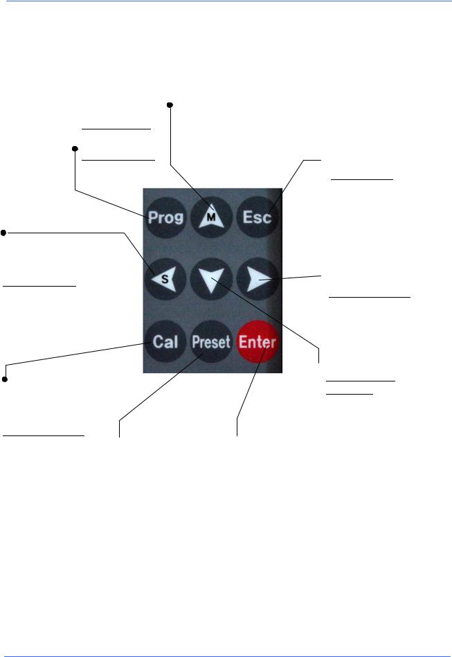
1.4 KEYPAD CONFIGURATION
Program
Measuring mode
Access to the programming mode Programming mode
No function
Move upward
Measuring mode Select M1, M2, M3, M4 Programming mode
Used to move from a specific menu to other menu, or to increase the values when setting the values of variables.
 Escape
Measuring mode Initialization of dynamic mode Programming mode
Escape to previous menu.
Move left
Measuring mode
Send data
Programming mode
Used to move from a specific menu to other or move the selected LED to the next left LED
Move right
Measuring mode
 No function
Programming mode
Used to move from a specific menu to other or move the selected LED to the next right LED
Calibration
Measuring mode Calibration functions Programming mode
No functions
 Preset
Measuring mode
Used to set the current measured values to 0 or pre-selected values
(See page 20) Programming mode No function
 Move downward
Measuring mode
No function
Programming mode
 Enter
Enter
Measuring mode Instrument OFF Enter + ON = Reset Programming mode
Used to move from a specific menu to other menu, or to decrease the values when setting the values of variables.
Used to select the current menu or to set values of variables
BOWERS METROLOGY |
page 7 /32 |
version 2.06 -E |

PC-2200
1.5 STATUS PANEL
Metric display (mm) |
Inch display |
|
Range |
Range |
|
±1000µm / ±1 mm |
||
± 0.05 inch |
||
|
||
Range |
Range |
|
±500µm / ±0.5 mm |
||
± 0.01 inch |
||
|
||
Range |
Range |
|
±100µm / ±0.1 mm |
± 0.005 inch |
|
Range |
Range |
|
±50µm / ±0.050 mm |
± 0.001 inch |
|
Range |
Range |
|
±10µm / ±0.01 mm |
± 0.0005 inch |
|
Range |
Range |
|
±5µm / ±0.005 mm |
± 0.0001 inch |
Measure number
BOWERS METROLOGY |
page 8 /32 |
version 2.06 -E |

PC-2200
Chapter 2. Installation
2.1 MECHANICAL INSTALLATION
Fix the column on the aluminum base and lock it with the 2 screws (M6 x16)
Connect the power supply cable (A) .
Connect the probe cable to the analog board (B)
Switch (ON) I.
A
 B
B
BOWERS METROLOGY |
page 9 /32 |
version 2.06 -E |

PC-2200
2.4 ELECTRICAL INSTALLATION
Switching the Voltage from 230V(110V) to 110V(230V).
Remove the cover by unscrewing the 8 screws.
Move the connector A on 110V or 230V.
A
Power supply (PCB) |
3P- |
|
Male |
|
Transformer |
|
220V |
(Default) |
0V |
110V |
to noise filter module
2P-female
BOWERS METROLOGY |
page 10 /32 |
version 2.06 -E |
 Loading...