


CT8.2 LCR
Owner’s Manual

Owner details
Title, first name, surname
Address
Town, postcode, country
e-mail address
Model
Serial number
Date of purchase
Dealer name
Address
Town, postcode, country
e-mail address
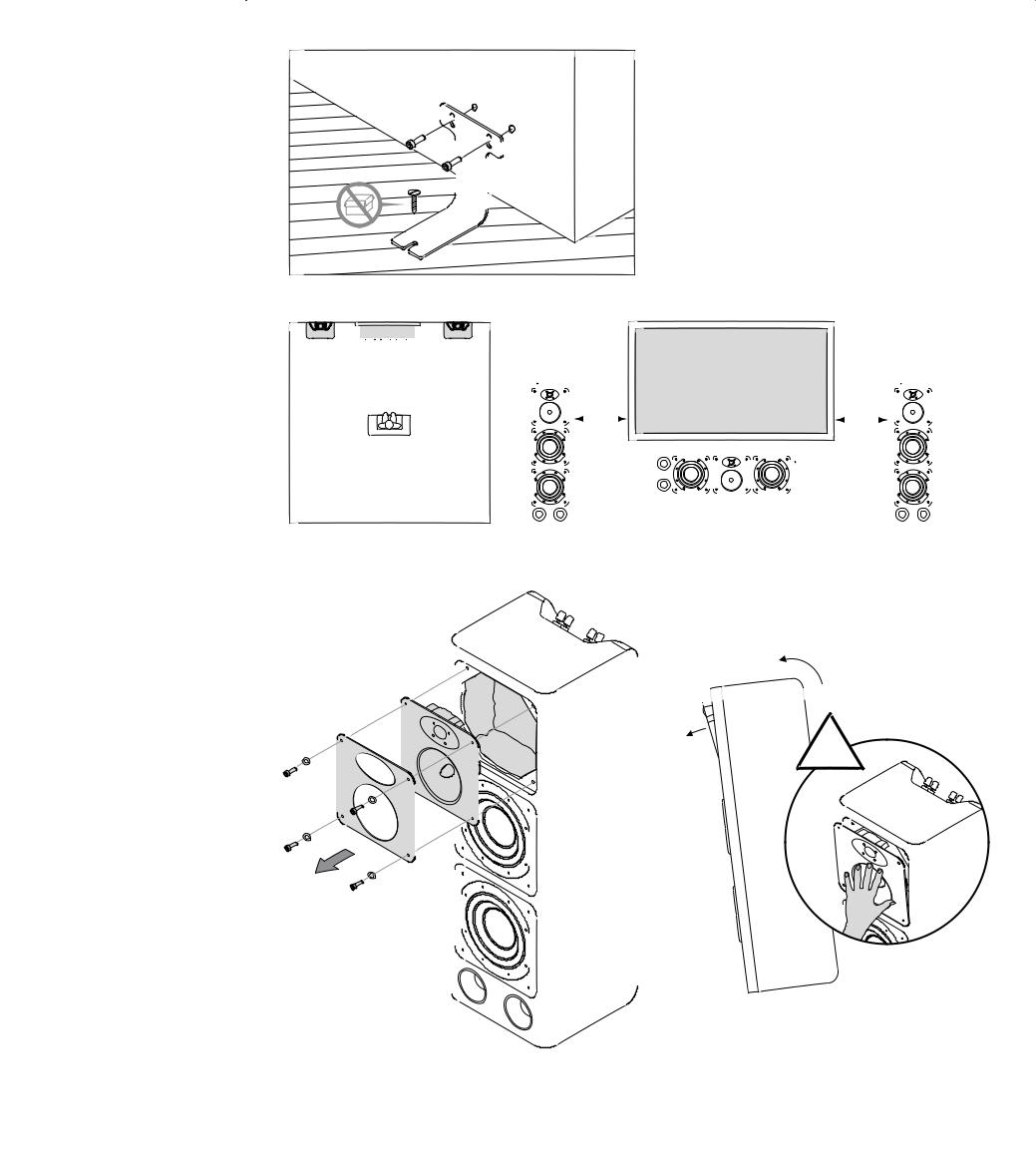
Figure 1
Figure 2
~0.5m |
~0.5m |
(20 in) |
(20 in) |
Figure 3a
!
1
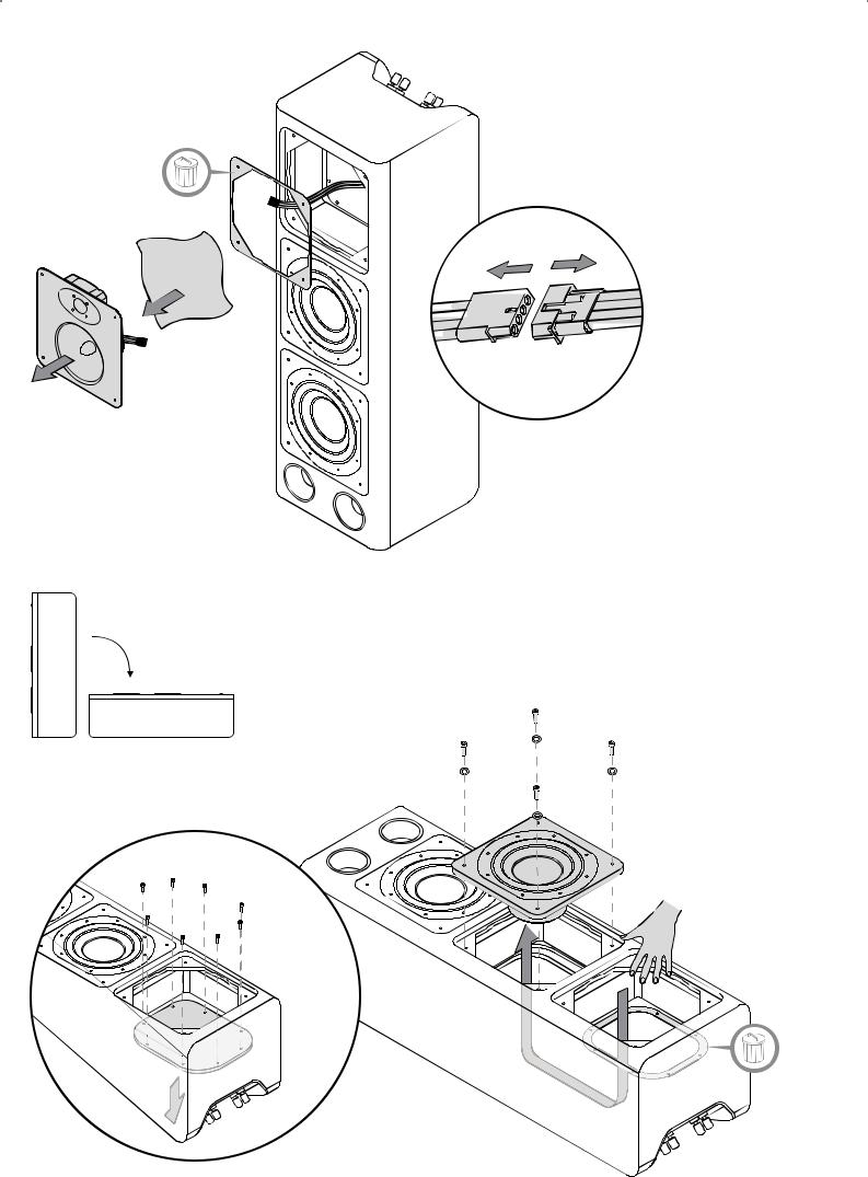
Figure 3b
Figure 3c
2

Figure 3d
Figure 3e
3

Figure 3f
 = 1.70Nm
Figure 3g
 = 1.70Nm
90º
4
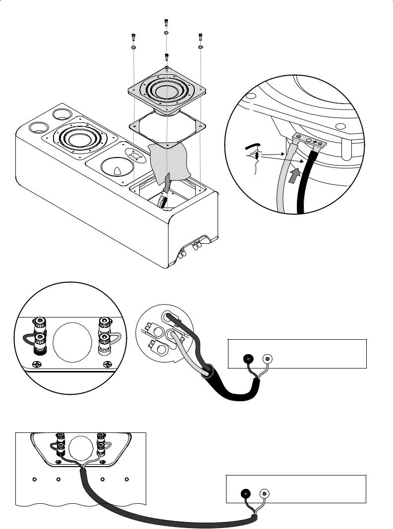
Figure 3h
Figure 4a
2+ 
2-
 = 1.70Nm
Amplifier
OUTPUT |
|
- |
+ |
Figure 4b
Amplifier
T +
5

Figure 5a
2+ 
2-
Figure 5b
HF |
HF |
LF |
LF |
Polar Response Horizontal |
|
|
|
||
|
95 90 |
|
Curve |
Freq |
DI |
dBSPL |
75 |
|
500.00 |
5.4 |
|
|
90 |
60 |
|
1.00K |
7.5 |
|
85 |
|
|
||
|
45 |
|
2.00K |
11.4 |
|
|
80 |
|
|||
|
|
|
|
|
|
|
75 |
30 |
|
4.00K |
11.6 |
|
70 |
|
8.00K |
6.2 |
|
|
|
|
|||
|
65 |
|
|
16.00K |
12.2 |
|
60 |
|
|
||
|
|
15 |
|
|
|
|
55 |
|
|
|
|
|
|
|
|
|
|
|
50 |
|
|
|
|
|
45 |
|
0 Deg |
|
|
|
50 |
|
|
|
|
|
55 |
|
|
|
|
|
60 |
|
-15 |
|
|
|
65 |
|
|
|
|
|
70 |
-30 |
|
|
|
|
75 |
|
|
|
|
|
|
|
|
|
|
|
80 |
-45 |
|
|
|
|
85 |
|
|
|
|
|
|
|
|
|
|
|
90 |
-60 |
|
|
|
|
95 |
|
|
|
|
|
-75 |
|
|
|
|
|
-90 |
|
|
|
|
|
|
|
|
|
|
Amplifier
|
OUTPUT |
|
|
+ |
- |
- |
+ |
Amplifier
+ |
- |
- |
+ |
Polar Response Vertical
|
95 90 |
Curve |
Freq |
DI |
dBSPL |
75 |
500.00 |
8.8 |
|
|
90 |
60 |
1.00K |
5.8 |
|
85 |
|
||
|
45 |
2.00K |
5.0 |
|
|
80 |
|||
|
75 |
30 |
4.00K |
12.3 |
|
70 |
8.00K |
9.5 |
|
|
|
|||
|
65 |
|
16.00K |
12.4 |
|
60 |
15 |
||
|
|
|
||
|
55 |
|
|
|
|
|
|
|
|
|
50 |
|
|
|
|
45 |
0 Deg |
|
|
|
50 |
|
|
|
|
55 |
|
|
|
|
60 |
-15 |
|
|
|
65 |
|
|
|
|
70 |
-30 |
|
|
|
75 |
|
|
|
|
|
|
|
|
|
80 |
-45 |
|
|
|
85 |
|
|
|
|
|
|
|
|
|
90 |
-60 |
|
|
|
95 |
-75 |
|
|
|
-90 |
|
|
|
Polar Response Horizontal |
Polar Response Vertical |
dBSPL |
95 |
90 |
75 |
|
|
|
dBSPL |
95 |
90 |
75 |
|
|
|
90 |
|
60 |
Curve |
Freq |
DI |
90 |
|
60 |
Curve |
Freq |
DI |
||
|
85 |
|
|
45 |
500.00 |
7.6 |
|
85 |
|
45 |
|
500.00 |
5.5 |
|
80 |
|
|
1.00K |
5.4 |
|
80 |
|
|
1.00K |
5.5 |
||
|
|
|
|
|
|
|
|
||||||
|
75 |
|
|
|
|
75 |
|
|
|
||||
|
|
|
30 |
2.00K |
9.4 |
|
|
30 |
|
2.00K |
4.5 |
||
|
70 |
|
|
|
70 |
|
|
||||||
|
|
|
|
4.00K |
10.6 |
|
|
|
|
4.00K |
12.4 |
||
|
65 |
|
|
|
|
65 |
|
|
|
||||
|
60 |
|
|
15 |
8.00K |
6.1 |
|
60 |
|
15 |
|
8.00K |
6.4 |
|
55 |
|
|
|
16.00K |
10.8 |
|
55 |
|
|
|
16.00K |
12 |
|
50 |
|
|
|
|
50 |
|
|
|
||||
|
|
|
|
|
|
|
|
|
|
|
|
||
|
45 |
|
|
0 Deg |
|
|
|
45 |
|
0 Deg |
|
|
|
|
50 |
|
|
|
|
|
|
50 |
|
|
|
|
|
|
55 |
|
|
|
|
|
|
55 |
|
|
|
|
|
|
60 |
|
|
-15 |
|
|
|
60 |
|
-15 |
|
|
|
|
65 |
|
|
|
|
|
|
65 |
|
|
|
|
|
|
70 |
|
|
-30 |
|
|
|
70 |
|
-30 |
|
|
|
|
|
|
|
|
|
|
75 |
|
|
|
|
||
|
75 |
|
|
|
|
|
|
|
|
|
|
||
|
|
|
|
|
|
|
|
|
|
|
|
||
|
80 |
|
|
-45 |
|
|
|
80 |
|
-45 |
|
|
|
|
85 |
|
|
|
|
|
85 |
|
|
|
|
||
|
|
|
|
|
|
|
|
|
|
|
|||
|
90 |
|
-60 |
|
|
|
|
90 |
|
-60 |
|
|
|
|
95 |
|
|
|
|
|
95 |
|
-75 |
|
|
|
|
|
-90 |
-75 |
|
|
|
|
-90 |
|
|
|
|||
|
|
|
|
|
|
|
|
|
|
|
|||
|
|
|
|
|
|
|
|
|
|
|
|
|
6

Contents
English |
|
Русский |
|
|
Owner’s Manual........................................ |
8 |
Руководство по эксплуатации............. |
22 |
|
Limited Warranty....................................... |
9 |
Ограниченная гарантия....................... |
24 |
|
Français |
|
"esky |
|
|
Manuel d’utilisation................................. |
10 |
Návod k pouãití...................................... |
24 |
|
Garantie limitée....................................... |
11 |
Záruka................................................... |
25 |
|
Deutsch |
|
Polski |
|
|
Bedienungsanleitung............................... |
12 |
Instrukcja uÃytkownika........................... |
26 |
|
Garantie................................................. |
13 |
Gwarancja............................................. |
27 |
|
Español |
|
|
|
|
Manual de instrucciones......................... |
14 |
................................................ |
28 |
|
Garantía limitada..................................... |
15 |
................................................ |
29 |
|
Italiano |
|
|
|
|
Manuale di istruzioni............................... |
16 |
................................................ |
30 |
|
Garanzia limitata..................................... |
17 |
................................................ |
30 |
|
Nederlands |
|
|
|
|
Handleiding............................................ |
18 |
EU Declaration of Conformity |
35 |
|
Garantie |
19 |
|||
Technical Specifications |
36 |
|||
Ελληνικά |
|
|||
20 |
|
|
||
δηγίες ρήσεως................................ |
|
|
||
Περι ρισµένη εγγύηση........................ |
21 |
|
|
7

English
Owner’s manual
Dear customer,
Thank you for choosing Bowers & Wilkins. Please read this manual fully before unpacking and installing the product. It will help you to optimise its performance. B&W maintains a network of dedicated distributors in over 60 countries who will be able to help you should you have any problems your dealer cannot resolve.
Environmental Information
All B&W products are designed to comply with international directives on the Restriction of Hazardous Substances (RoHS) in electrical and
 electronic equipment and the disposal of Waste Electrical and Electronic Equipment (WEEE). These symbols indicate compliance and that the products must be appropriately recycled or processed in accordance with these directives. Consult your local waste disposal authority for guidance.
Carton Contents
Check in the carton for:
1 Speakon plug
2 x foot brackets
4 x M6 bolts
2 x Foam Plugs
2 x Baffle Gaskets
1 x Panel Gasket
1 x 5mm Allen Key
Speaker Installation
The CT8.2 speaker is intended for use in home theatre front and centre channel applications. In centre channel applications it can be used in either standard vertical (portrait) orientation or reconfigured to horizontal (landscape) orientation by swapping the positions of its mid/high frequency driver module and upper bass driver module. Reconfiguring a CT8.2 for horizontal centre channel use is covered in a later section of this manual.
The CT8.2 is intended to be either floor mounted or incorporated within custombuilt furniture. Foot brackets are supplied to secure the speaker. The foot brackets are designed to stop the speaker toppling forward if standing on the floor, a shelf or other flat supporting structure. The foot brackets attach to the back of the CT8.2s via M6 threaded holes. Using the supplied M6 bolts, securely attach the foot brackets to the CT8.2 back panels. The brackets should be secured such that their flat section rests on the floor. The single slotted hole can then be used to attach the bracket to the supporting surface. Use an appropriate screw and a plug if necessary. Figure 1 Illustrates use of the foot bracket.
Regardless of the style of installation, take care when lifting the speaker into position. It is unwieldy and heavy and best handled by two people working together. B&W can accept no liability for any failure of walls, floors, furniture and/or fixings.
Speaker Positioning
CT8.2 speakers used for the front channels in a home theatre system should be positioned on the floor or built in to furniture units one on each side of the screen. They should be within approximately 0.5m (20 in) of the sides of the screen to help keep the sound image in scale with the visual image. See Figure 2.
A CT8.2 speaker used for the centre channel in a home theatre system should be positioned in horizontal orientation centrally either directly above or below the screen. In the case of acoustically transparent screens, the centre channel speaker should be positioned centrally behind the screen. In this case, standard vertical configuration of the CT8.2 may be appropriate. See Figure 2.
CT8.2 Landscape Centre Channel Configuration
The CT8.2 can be reconfigured to operate as a horizontal (landscape) format centre channel speaker by swapping the positions of its upper bass driver and mid/high frequency driver modules. The mid/high frequency driver module must also be rotated by ninety degrees. The procedure is described below and illustrated in the accompanying figures.
You will need an M5 and an M4 hexagonal driver, and space to lay the speaker on its back and work around it. A second person to assist is also recommended. Take great care throughout the procedure. The speaker drivers in particular are delicate, precision components that can be damaged by inappropriate handling. It is therefore also recommended to use the tweeter protection cover throughout the entire procedure.
Step 1 (Figure 3a)
With the speaker upright, unscrew and remove the four M5 bolts retaining the mid/ high frequency driver module in the cabinet. Restrain the module with one hand as the last bolt is removed to negate the possibility of it falling. Put the screws, washers and the trim plate to one side.
Step 2 (Figure 3a)
The module may begin to fall forward as you remove your hand. If it does, it may be drawn carefully away from the cabinet. If it does not, you may need to tip the cabinet forward slightly in order to free the module and gain some purchase on it. Keep a hand on the module as you tip the cabinet.
Step 3 (Figure 3b)
As the mid/high frequency driver module is moved away from the cabinet, its connecting cables will be revealed. The in-line connector positioned halfway along the cables must be disconnected. While a helper supports the driver module, hold each side of the connector and pull it apart.
Step 4 (Figure 3b)
Once the mid/high frequency driver module is disconnected, it can be withdrawn completely from the cabinet and placed to one side. The wadding material from behind the module should also be removed and placed to one side. The mid/high frequency driver module sealing gasket should be removed and discarded.
Step 5 (Figure 3c)
The speaker should now be gently laid on its back for removal of the upper bass driver module. Remove the four M5 bolts retaining the bass driver module in the cabinet. Place the bolts and washers to one side.
Step 6 (Figure 3c)
Push the bass driver module from behind to release it. In order to gain access to the back of the module the removable panel in the cabinet behind the mid/high frequency driver module must be removed. Unscrew and remove the eight M4 bolts securing the panel and drop it through the hole. Remove and discard the gasket. Place the bolts to one side. Put your hand through the hole to reach the back of the bass driver module and carefully push it upwards.
Step 7 (Figure 3d)
Once the bass driver module has been pushed upwards slightly from inside the cabinet it can be lifted away. After noting the orientation of the coloured cables, disconnect the driver by pulling the tags off the connection spades. Place the bass driver module to one side. The wadding material from behind the module should also be removed and placed to one side. The bass driver module sealing gasket should be removed and discarded.
Step 8 (Figure 3e)
The cables for the bass driver module and mid/high frequency module can now be swapped to their new locations. Feed the mid/high frequency cables, including the attached internal panel, through the cabinet to the region vacated by the bass driver module. Feed the bass driver cables to the region of the cabinet vacated by the mid/ high frequency module.
Step 9 (Figure 3f)
Position and re-secure the internal panel in the new mid/high frequency region of the cabinet using a new gasket and the eight M4 bolts. Tighten the bolts to a torque of 1.70Nm. Be careful that no wadding gets trapped as the panel is screwed down.
Step 10 (Figure 3g)
Replace the wadding in the mid/high frequency module cavity and position a new gasket on its cabinet mating surface. Take the mid/high frequency module, reconnect the in-line connector and position the module on the cabinet rotated by 90° so that the tweeter is positioned adjacent to one edge. Position the trim plate and replace the four M5 screws and washers. Tighten the screws to a torque of 1.70Nm.
Note: It is not generally significant which side of the cabinet the tweeter is located (i.e. if the mid/high frequency module is rotated 90° clockwise or anti-clockwise).
Step 11 (Figure 3h)
Replace the wadding in the bass driver module cavity and position a new gasket on its cabinet mating surface. Take the bass driver module, reconnect the push-on tags to the driver and position the module on the cabinet. Replace the M5 screws and washers and tighten them to a torque of 1.70Nm. The reconfigured CT8.2 is now ready for use as a landscape format centre channel speaker.
Note: It is potentially possible to reconnect bass driver with the wrong polarity. To check bass driver polarity following reconnection, briefly connect a 1.5V battery to the bass input terminals, with the positive terminal of the battery connected to the positive input terminal. Both cones should move outwards.
Stray Magnetic Fields
The speaker drive units create stray magnetic fields that extend beyond the boundaries of the cabinet. We recommend you keep magnetically sensitive articles (CRT television and computer screens, computer discs, audio and video tapes, swipe cards and the like) at least 0.5m (20 in) from the speaker. LCD and plasma screens are not affected by magnetic fields.
Connections
All connections should be made with the equipment switched off.
CT8.2 speakers have two pairs of binding post connection terminals and one Neutrik® Speakon connection socket on their back panels. The binding post terminals provide quick and easy connection of stripped wires while Speakon sockets provide a more secure and reliable connection method. Both Speakon and binding post terminal connection methods provide the opportunity to bi-wire the speakers.
To connect the speakers in conventional single-wire mode using the Speakon option, insert a short length of stripped cable through the body of each binding post terminal and tighten the terminal head then disassemble the Speakon plug as shown in Figure 4a and connect the positive cable to the terminal marked +1 and the negative cable to the terminal marked -1. Incorrect connection can result in poor imaging and loss of bass. Once the plug is reassembled it can be inserted into the socket and locked by twisting clockwise.
To connect the speakers in conventional single-wire mode using the binding post terminals, insert a short length of stripped cable through the body of each terminal and tighten the terminal head. Connect the positive cable to one of the red terminals and the negative cable to the corresponding black terminal as illustrated in Figure 4b. Incorrect connection can result in poor imaging and loss of bass.
To connect the speakers in bi-wire mode using either the binding post terminals or the Speakon socket
If the Speakon option is to be used, disassemble the Speakon plug as shown in Figure 5a and connect one pair of positive and negative cables to the terminals marked +1 and -1 and the second pair of positive and negative cables to the
8
terminals marked +2 and -2. Ensure that positive cables are connected to the + terminals and the negative cables connected to the – terminals. Incorrect connection can result in poor imaging and loss of bass. Once the plug is reassembled it can be inserted into the socket and locked by twisting clockwise.
If the binding post terminals are to be used, connect one pair of positive and negative cables to the terminals marked LF and the second pair of positive and negative cables to the terminals marked HF. Ensure that positive cables are connected to the red terminals and the negative cables connected to the black terminals as illustrated in Figure 5b. Incorrect connection can result in poor imaging and loss of bass.
Ask your dealer for advice when selecting speaker cable. Keep its total impedance below the maximum recommended in the speaker specification and use a low inductance cable to avoid attenuation of high frequencies.
Neutrik® and the names of Neutrik® products referenced herein are either trademarks and/or service marks of Neutrik®.
Fine Tuning
Before fine tuning, make sure that all the connections in the installation are correct and secure.
If the sound is too bright, increasing the amount of soft furnishing in the room (heavier curtains for example) may help balance the sound. Conversely, reducing the amount of soft furnishing may help brighten a dull sound.
Some rooms suffer from “flutter echoes” – echoes that “bounce” between parallel room boundaries. Flutter echoes can colour the sound of the speakers in the room. Test for flutter echoes by standing in the middle of the room and clapping your hands. Flutter echoes can be reduced by placing irregular shaped items or non-reflective surfaces, bookshelves, rugs or pictures for example, on one of the offending walls or floor.
Running-in Period
The performance of the speaker will change subtly during the initial listening period. If the speaker has been stored in a cold environment, the damping compounds and suspension materials of the drive units will take some time to recover their correct mechanical properties. The drive unit suspensions will also loosen up during the first hours of use. The time taken for the speaker to achieve its intended performance will vary depending on previous storage conditions and how it is used. As a guide, allow up to a week for the temperature effects to stabilise and 15 hours of average use for the mechanical parts to attain their intended design characteristics.
However, longer run-in periods (as long as a month) have been reported and there is evidence to suggest that this has little to do with the speaker changing and more to do with the listener getting used to the new sound. This is especially so with highly revealing speakers such as these where there may be a significant increase in the amount of detail compared with what the listener has previously been used to; the sound may at first appear too “up front” and perhaps a little hard. After an extended period of time the sound will seem to mellow, but without losing clarity and detail.
Aftercare
The cabinet surfaces usually only require dusting. If you wish to use an aerosol or other cleaner, remove the grille first by gently pulling it away from the cabinet. Spray aerosols onto the cleaning cloth, not directly onto the product. Test a small area first, as some cleaning products may damage some of the surfaces. Avoid products that are abrasive, or contain acid, alkali or anti-bacterial agents. Do not use cleaning agents on the drive units. The grille fabric may be cleaned with a normal clothes brush whilst the grille is detached from the cabinet. Avoid touching the drive units, especially the tweeter, as damage may result.
Limited Warranty
This product has been designed and manufactured to the highest quality standards. However, if something does go wrong with this product, B&W Group Ltd. and
its national distributors warrant free of charge labour (exclusion may apply) and replacement parts in any country served by an official B&W distributor.
This limited warranty is valid for a period of five years from the date of purchase or two years for electronics including amplified loudspeakers.
Terms and Conditions
1The warranty is limited to the repair of the equipment. Neither transportation, nor any other costs, nor any risk for removal, transportation and installation of products is covered by this warranty.
2This warranty is only valid for the original owner. It is not transferable.
3This warranty will not be applicable in cases other than defects in materials and/ or workmanship at the time of purchase and will not be applicable:
a.for damages caused by incorrect installation, connection or packing,
b.for damages caused by any use other than correct use described in the user manual, negligence, modifications, or use of parts that are not made or authorised by B&W,
c.for damages caused by faulty or unsuitable ancillary equipment,
d.for damages caused by accidents, lightning, water, fire heat, war, public disturbances or any other cause beyond the reasonable control of B&W and its appointed distributors,
e.for products whose serial number has been altered, deleted, removed or made illegible,
f.if repairs or modifications have been executed by an unauthorised person.
4This guarantee complements any national/regional law obligations of dealers or national distributors and does not affect your statutory rights as a customer.
How to claim repairs under warranty
Should service be required, please follow the following procedure:
1If the equipment is being used in the country of purchase, you should contact the B&W authorised dealer from whom the equipment was purchased.
2If the equipment is being used outside the country of purchase, you should contact the B&W national distributor in the country of residence who will advise where the equipment can be serviced. You can call B&W in the UK or visit our web site to get the contact details of your local distributor.
To validate your warranty, you will need to produce the warranty booklet completed and stamped by your dealer on the date of purchase. Alternatively, you will need the original sales invoice or other proof of ownership and date of purchase.
9

Français
Manuel d’utilisation
Cher Client,
Nous vous remercions d’avoir choisi Bowers & Wilkins. Veuillez lire soigneusement ce manuel avant de déballer et d’installer vos enceintes acoustiques. Il vous aidera à en obtenir les performances optimales. B&W est distribué dans plus de 60 pays dans le monde entier, par l’intermédiaire de distributeurs spécialement sélectionnés ; ceux-ci pourront vous aider à résoudre d’éventuels problèmes ignorés par votre revendeur.
Information sur la protection de l’environnement
Tous les produits B&W sont conçus en conformité totale avec les normes internationales concernant l’interdiction d’utilisation de
 certaines substances dangereuses (RoHs) dans les équipements électriques et électroniques, ainsi que la possibilité de recyclage des matériaux utilisés (WEEE, pour Waste Electrical and Electronic Equipment). Ces symboles indiquent la compatibilité avec ces directives, et le fait que les appareils peuvent être correctement recyclés ou traités dans le respect total de ces normes. Consultez l'organisme officiel de votre région pour le traitement des produits.
Vérification du contenu de l’emballage
Vérifiez que le carton contienne bien :
1 prise Speakon
2 x supports
4 x vis M6
2 x tampons mousse
2 x intercalaires de baffle
1 x intercalaire de panneau
1 x clé Allen 5 mm
Installation des enceintes
L’enceinte CT8.2 est conçue pour être utilisée dans les applications Home Cinema, en enceinte avant, latérale ou centrale. En enceinte centrale, elle peut être utilisée en utilisation verticale (portrait), ou configurée pour son utilisation horizontale (paysage), en orientant la position de son module médium/aigu et celle de son module supérieur de grave. Cette configuration en utilisation horizontale est expliquée plus loin dans ce manuel.
L’enceinte CT8.2 est conçue pour être posée sur le sol ou intégrée dans un mobilier existant. Des pieds spéciaux sont fournis pour assurer son positionnement correct au sol. Ces supports sont conçus pour éviter tout basculement vers l’avant si l’enceinte est posée sur le sol ou sur une étagère, ou tout autre support plan. Ces supports se fixent à l’arrière des CT8.2 via les trous filetés pour vis M6 présents. Les supports doivent être fixés de telle manière que leur surface plane repose sur le sol. Le trou oblong peut ensuite être utilisé pour fixer le pied sur son support. Utilisez une vis appropriée pour ce faire, avec éventuellement une cheville spéciale. La Figure 1 illustre l’utilisation de ce pied de sol.
Quel que soit le mode d’installation choisi, toujours manipuler l’enceinte avec le plus grand soin pendant la procédure d’installation. Ses dimensions et son poids
nécessitent la participation de deux personnes pour une manipulation sans problème. B&W ne pourra accepter aucune prise en charge au titre de la garantie, pour tout dommage survenant d’un problème de fixation à cause des murs, des sols, des meubles et/ou des fixations utilisés.
Choix de la position
Les enceintes CT8.2 utilisées comme enceintes avant d’un système Home Cinema doivent être posées sur le sol ou intégrées dans un meuble, de part et d’autre de l’écran. Elles doivent être installées à environ 0,5 mètre (20 in) des côtés de l’écran, afin de conserver une taille de l’image sonore correspondante à celle de l’image proprement dite. Voir Figure 2.
Une enceinte CT8.2 utilisée comme enceinte centrale avant d’un système Home Cinema doit être positionnée horizontalement au centre de l’écran, juste au-dessus ou au-dessous de celui-ci. Avec un écran transparent acoustiquement, elle pourra être installée exactement derrière l’écran, au centre de celui-ci. Dans ce cas, une utilisation en position verticale peut parfaitement convenir. Voir Figure 2.
Configuration de la CT8.2 en enceinte centrale positionnée horizontalement (paysage)
La CT8.2 peut être reconfigurée pour fonctionner en position horizontale, en faisant pivoter ses modules de grave supérieur et de médium/aigu. Le module médium/aigu doit alors être pivoté de 90 degrés. La procédure à suivre est décrite ci-dessous, et illustrée par les figures d’accompagnement ci-dessous.
Vous aurez besoin d’un tournevis hexagonal M5 et M4, et des intercalaires fournis pour poser l’enceinte sur sa face arrière et travailler dessus. La présence d’une seconde personne, pour vous assister, est recommandée. Les haut-parleurs des enceintes, notamment, sont relativement fragiles, et ils peuvent être endommagés lors de manœuvres malencontreuses. Il est également recommandé de protéger le tweeter pendant toute la durée de l’opération.
Étape 1 (Figure 3a)
L’enceinte étant posée verticalement, dévissez et retirez les quatre écrous M5 retenant le module médium/aigu sur l’enceinte. Retenez l’ensemble du module avec une main pendant que vous retirez le dernier écrou, afin d’éviter toute chute du module. Conservez soigneusement de côté les vis, leurs rondelles et le support.
Étape 2 (Figure 3a)
Le module a dû vous tomber dans la main une fois les écrous retirés. Si c’est le cas, éloignez-le doucement de l’enceinte. Si ce n’est pas le cas, vous devez pencher doucement l’enceinte vers l’avant pour libérer le module et le dégager légèrement par
rapport à l’enceinte. Toujours le retenir avec une main pendant que vous manipulez l’enceinte de l’autre main.
Étape 3 (Figure 3b)
Une fois le module médium/aigu dégagé de l’enceinte, vous pouvez voir les câbles qui les relient entre eux. Le connecteur placé juste à côté des câbles doit être débranché. Avec une seconde personne pour vous aider en tenant le module, tirez de chaque côté du connecteur pour le débrancher.
Étape 4 (Figure 3b)
Une fois le module médium/aigu débranché par son connecteur, il peut être complètement désolidarisé de l’enceinte et posé à côté. Le matériau amortissant présent derrière le module doit être retiré et conservé à côté. Le joint de contact derrière le module doit être retiré.
Étape 5 (Figure 3c)
L’enceinte doit maintenant être doucement posée sur sa face arrière, afin de retirer le module supérieur du grave. Dévissez les quatre écrous M5 retenant le module de grave sur l’enceinte, et conservez soigneusement ces écrous et leurs rondelles.
Étape 6 (Figure 3c)
Poussez le module de grave par l’arrière pour le libérer. Afin d’accéder à l’arrière de ce module, le panneau amovible de l’enceinte, positionné derrière le module médium/ aigu, doit être retiré. Dévissez et retirez les huit écrous M4 qui maintiennent ce panneau et laissez-le tomber dans le trou ainsi créé. Retirez l’intercalaire. Conservez soigneusement les écrous. Passez alors la main dans le trou ainsi formé, pour atteindre l’arrière du module de grave, puis poussez doucement vers l’avant.
Étape 7 (Figure 3d)
Une fois que le module de grave a commencé à se désolidariser, par l’avant, de l’enceinte, il peut être complètement dégagé. Après avoir soigneusement repéré la couleur des câbles et leur orientation, débranchez-les du haut-parleur en tirant. Retirez alors le module de grave, et posez-le à côté. Retirez aussi le matériau amortissant derrière le module, et conservez-le également à côté de vous. Le joint présent derrière le module de grave doit enfin être retiré.
Étape 8 (Figure 3e)
Les câbles prévus respectivement pour le module médium/aigu et pour le module de grave doivent maintenant être interchangés pour passer dans leur nouvelle position. Passez le câble du médium/aigu, y compris avec le panneau interne qu’il traverse, dans la zone laissée libre par le module de grave. Puis passez les câbles du module de grave dans la zone laissée libre par le module médium/aigu.
Étape 9 (Figure 3f)
Positionnez et fixez à nouveau le panneau interne dans la nouvelle zone réservée au module médium/aigu, en utilisant le nouvel intercalaire (fourni) et les huit écrous M4. Serrez fermement les écrous (couple 1,7 Nm). Assurez-vous qu’aucune portion du matériau amortissant ne se retrouve pincée par le panneau avant de le revisser.
Étape 10 (Figure 3g)
Replacez le matériau amortissant derrière la cavité du module médium/aigu, placez un nouvel intercalaire sur la surface du baffle. Prenez le module médium/aigu, rebranchez son connecteur électrique et positionnez le module dans une position différente de 90° de sa position précédente, de telle manière que le tweeter se trouve maintenant près d’un angle. Replacez la plaque puis les quatre écrous M5 avec leurs rondelles. Vissez fermement les écrous, avec un couple de 1,7 Nm.
Note : le côté vers lequel le tweeter est maintenant orienté (suivant que vous avez tourné de 90° le module médium/aigu dans le sens, ou le sens inverse des aiguilles d’une montre, n’est pas important).
Étape 11 (Figure 3h)
Replacez le matériau amortissant derrière le module de grave et placez aussi un nouvel intercalaire (fourni) sur la surface du baffle. Prenez le module de grave, reconnectez les cosses du haut-parleur et positionnez le module dans l’enceinte. Replacez les vis M5 avec leurs rondelles, et serrez-les fermement avec un couple de 1,7 Nm. La nouvelle CT8.2 « reconfigurée » est maintenant prête à être utilisée, mais en position horizontale (paysage), comme enceinte centrale.
Note : Il est possible d’inverser la polarité du haut-parleur de grave lorsqu’on rebranche ses cosses. Pour vérifier la polarité correcte du haut-parleur, branchez brièvement une pile de 1,5 V sur les prises d’entrée du grave, avec la prise positive
(+) de la pile sur l’entrée positive de l’enceinte. Les deux membranes doivent se déplacer simultanément vers l’avant.
Champs magnétiques
Les haut-parleurs à l’intérieur de l’enceinte génèrent des champs magnétiques qui peuvent s’étendre
au-delà du coffret de l’enceinte. Nous vous recommandons donc de tenir éloignés d’au moins 50 centimètres des enceintes les appareils sensibles à ces champs magnétiques (télévisions et moniteurs informatiques à tube cathodique CRT, cassettes et bandes magnétiques audio et vidéo, cartes magnétiques, etc.). Les écrans de type plasma et LCD ne sont pas affectés par ces champs magnétiques.
Branchements
Tous les branchements doivent être effectués les appareils étant tous éteints.
Les enceintes CT8.2 possèdent deux paires de bornes de branchement et une prise Neutrik® Speakon sur leur face arrière. Les bornes à vis constituent le moyen le plus simple et le plus rapide d’effectuer le branchement via une liaison par câble à conducteurs simplement dénudés, tandis que la prise Speakon constitue une méthode plus sûre et plus fiable dans le temps. Les deux modes de connexion, bornes vissantes ou prise Speakon, permettent de bi-câbler les enceintes.
Pour brancher les enceintes en mode monocâblage avec la prise Speakon, insérez une courte longueur de câble dénudé dans le corps principale de chaque prise, serrez fermement cette tête de prise puis démontez la prise Speakon comme illustré
10
 Loading...