

Page 1

BOSS MODEL INFINITY
PTO AIR COMPRESSOR
OPERATORS, MAINTENANCE
AND PARTS MANUAL
P/N: 307200
06/05/2008 MCM
Page 2

Page 3

OPERATORS, MAINTENANCE, AND PARTS MANUAL
BOSS INDUSTRIES INFINITY
Operation & Maintenance Section
TABLE OF CONTENTS
Operation & Maintenance Section
Specifications...................................................................................................................... 6
Safety .................................................................................................................................. 7
Compressor T erminology .................................................................................................. 11
Description of Components............................................................................................... 12
Inspection, Lubrication, and Maintenance.......................................................................... 16
Troubleshooting................................................................................................................. 24
Compressor Operation ...................................................................................................... 27
Parts and Illustration Section ............................................................................................. 29
Recommended Spare Parts ................................................................................................ 36
Service Questionnaire........................................................................................................ 37
Instructional Procedures for Installation ........................................................................... 38
Warranty Section
W arranty Information ........................................................................................................ 43
4
Page 4

Page 5
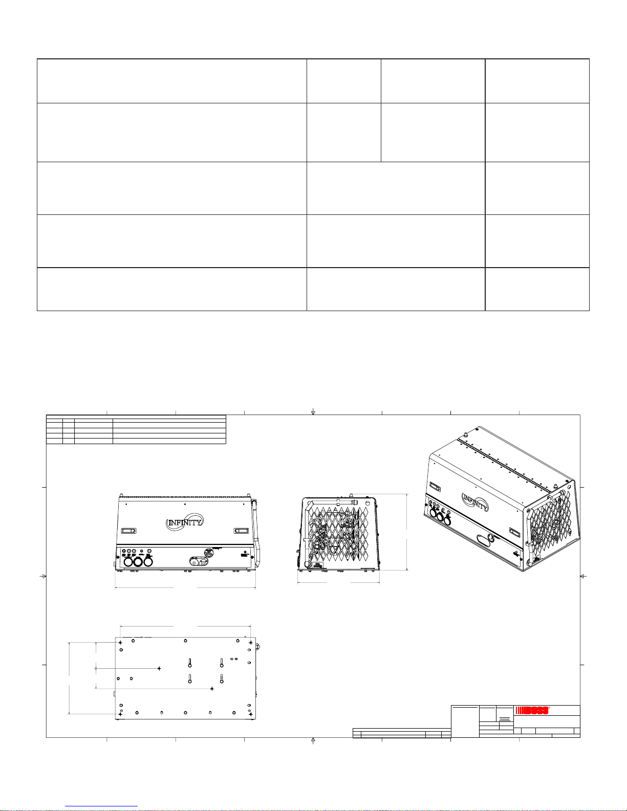
SPECIFICATIONS
GISP051@YREVILEDMFC5406
rosserpmoCotdeepStupnI
MPR
MPG
rosserpmoC-yticapaCdiulF
ciluardyhton(
)
metsySrosserpmoC-stnenopmoC
)
yrd(thgieW .sbl003
0051
@01
ISP0742
metsySsnollaG0.1
pmuSrosserpmoC57.
)snoisnemiDllarevO(
wolebees
1591
@31
ISP0742
SPECIFICATIONS SUBJECT TO CHANGE WITHOUT PRIOR NOTICE
8
D D
7
Parts List
COMPR MTG SYS, INFINITY 45-60-150 SCI8G 0820035311
ELEC SYS, INFINITY 45-60-150 SCI8G 08200355-999 12
OIL-AIR-HYD CLNG SYS, INFINITY SCI8G 08200356-999 13
CANOPY SYS, INFINITY 45-60-150 SCI8G 0820035414
DESCRIPTIONPART NUMBERQTYITEM
6
5
4
3
2
1
C C
34 3/4 in
[882.7 mm]
B B
6 3/8 in
[163.2 mm]
17 3/4 in
[450.9 mm]
5 in
[127.0 mm]
DIMENSIONS OF MOUNTING HOLES
32 1/4 in
[819.2 mm]
A A
8
7
6
19 in
[481.4 mm]
20 1/4 in
[514.4 mm]
PROPRIETARY INFORMATION
THIS DRAWING AND ALL ITS
CONTENTS ARE PROPERTY
OF BOSS INDUSTRIES, INC.
AND MUST NOT BE COPIED
OR MADE PUBLIC. IT IS
LOANED AND IS SUBJEC T TO
RETURN UPON DEMAND. THE
INFORMATION CONTAINED IN
THIS DRAWING IS
CONFIDENTIAL AND MU ST
REV DESCRIPTION DATE ENG
1
5
4
REVISION HISTORY
UPDATED 200353 TO REV 1, 200354 TO REV 1
3
5/22/2008 MCM
NOT BE USED, DIRECTLY OR
INDIRECTLY, IN ANY WAY
DETRIMENTAL TO THE
INTEREST OF BOSS
INDUSTRIES, INC.
UNMACHINED SURFACES
MACHINED SURFACES
NOMINAL DIM.
FRACTIONAL ` 1/16
`
.010
0.000 TO 1.000
`
.03
DECIMAL
`
.015
1.001 TO 5.000
`
1°
ANGULAR
`
.020
5.001 TO 10.000
DO NOT SCALE
TOLERANCES
`
.025
10.001 & OVER
UNLESS NOTED
DRAWN
12/3/2007
DCL
CHECKED
12/3/2007
NDD
MATERIAL
N/A
PATH
G:\Inventor Files\20k\20054-001.dwg
2
DESCRIPTION
INFINITY 45-60 SCI8G 08
SIZE
DWG NO
SCALE
1=4
20054-001
D
R
BOSS INDUSTRI ES
1761 GENESIS DR.
LA PORTE, IN 46350
SHEET
1
REV
1
1 1
OF
6
Page 6

SAFETY
WARNING
ALL UNITS ARE SHIPPED WITH A DET AILED OPERA TORS AND P ARTS
MANUAL. THIS MANUAL CONT AINS VITA L INFORMA TION FOR THE SAFE
USE AND EFFICIENT OPERA TION OF THIS UNIT . CAREFULLY READ
THE OPERAT ORS MANUAL BEFORE ST ARTING THE UNIT . F AILURE T O
ADHERE TO THE INSTRUCTIONS COULD RESULT IN SERIOUS BODILY
INJURY OR PROPERTY DAMAGE.
AIR COMPRESSOR SAFETY PRECAUTIONS
Safety is basically common sense. While there are standard safety rules, each situation has its own
peculiarities that cannot always be covered by rules. Therefore with your experience and common
sense, you are in a position to ensure your safety . Lack of attention to safety can result in:
accidents, personal injury , reduction of efficiency and worst of all - Loss of Life. W atch for safety
hazards. Correct them promptly . Use the following safety precautions as a general guide to safe
operation:
Do not attempt to remove any compressor parts without first relieving the entire system of
pressure.
Do not attempt to service any part while machine is operating.
DANGER
CHECK THE COMPRESSOR SUMP OIL LEVEL ONL Y WHEN THE COMPRESSOR
IS NOT OPERA TING AND SYSTEM IS COMPLETEL Y RELIEVED OF PRESSURE.
OPEN SERVICE VAL VE TO ENSURE RELIEF OF SYSTEM AIR PRESSURE WHEN
PERFORMING MAINTENANCE ON COMPRESSOR AIR/OIL SYSTEM. FAILURE
TO COMPL Y WITH THIS W ARNING MA Y CAUSE DAMAGE TO PROPERTY
AND SERIOUS BODIL Y HARM.
Do not operate the compressor at pressure(s) or speed in excess of its rating as indicated in
“Compressor Specifications”.
Periodically check all safety devices for proper operation.
Do not play with compressed air . Pressurized air can cause serious injury to personnel.
Exercise cleanliness during maintenance and when making repairs by covering parts and exposed
openings.
7
Page 7

SAFETY
Do not install a shut-off valve between the compressor and compressor oil sump.
DANGER
DO NOT USE BOSS INDUSTRIES COMPRESSOR SYSTEMS TO PROVIDE
BREA THING AIR. SUCH USAGE, WHETHER SUPPLIED IMMEDIA TELY FROM
THE COMPRESSOR SOURCE, OR SUPPLIED TO BREATHING TANKS FOR
SUBSEQUENT USE, CAN CAUSE SERIOUS BODIL Y INJURY.
BOSS INDUSTRIES, INC. DISCLAIMS ANY AND ALL LIABILITIES FOR DAMAGE
FOR LOSS DUE TO PERSONAL INJURIES, INCLUDING DEATH, AND/OR
PROPERTY DAMAGE INCLUDING CONSEQUENTIAL DAMAGES ARISING OUT
OF ANY BOSS INDUSTRIES, INC. COMPRESSORS USED T O SUPPL Y BREA THING
AIR.
Do not disconnect or bypass safety circuit system.
Do not install safety devices other than authorized BOSS INDUSTRIES, INC. replacement
devices.
Close all openings and replace all covers and guards before operating compressor unit.
T ools, rags, or loose parts must not be left on the compressor or drive parts.
Do not use flammable solvents for cleaning parts. This can cause the unit to ignite during operation.
Keep combustibles out of and away from the Compressor/Inlet and any associated enclosures.
The owner, lessor , or operator of the Compressor are hereby notified and forewarned that any
failure to observe these safety precautions may result in damage or injury .
BOSS INDUSTRIES, INC. expressly disclaims responsibility or liability for any injury or damage
caused by failure to observe these specified precautions or by failure to exercise that ordinary
caution and due care required when operating or handling the Compressor, even though not
expressly specified above.
8
Page 8
SAFETY
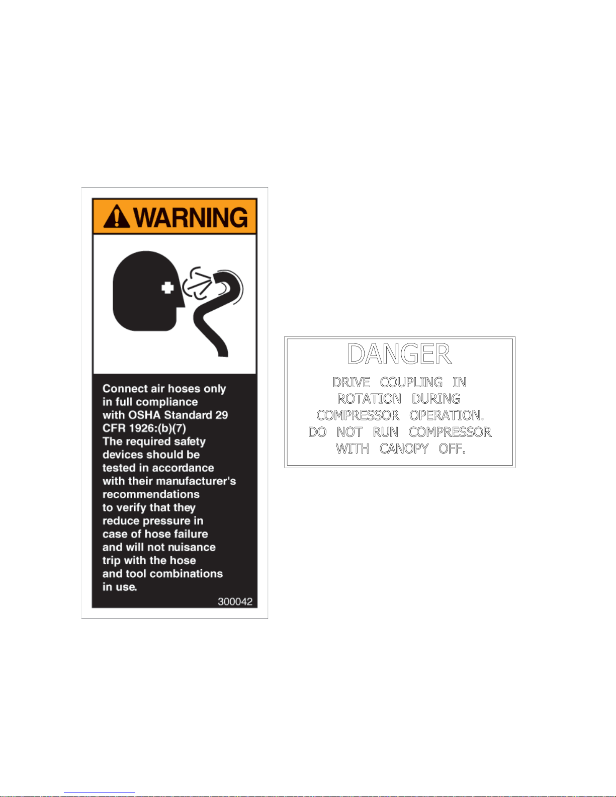
A compliment of warning decals is supplied with each unit. These decals must be affixed to the
comressor package in the locations noted in this manual. If for any reason a safety decal is
removed it is the owners responsibility to make sure it is replaced.
9
Page 9
SAFETY
10
Page 10

COMPRESSOR TERMINOLOGY
AIR/OIL COALESCER - Performs second stage separation of oil from compressed air feeding
air tools. Sometimes referred to as the separator element.
CFM - Refers to the volume of compressed air being produced, expressed as cubic feet of air per
minute.
COMPRESSOR LUBRICANT - DEXTRON III ATF.
GPM - Refers to the amount of gallons per minute of hydraulic fluid flowing through the pump.
OIL SUMP - The first stage of oil separation from compressed air . Also serves as reservoir area
for compressor lubricant and sometimes referred to as the receiver tank.
PSI - Refers to the operating pressure the system is set up at, expressed as pounds per square
inch.
SAFETY VALVE - A valve located on the oil sump which opens in case of excessive pressure.
Sometimes referred to as the pop-off or pressure relief valve.
11
Page 11

DESCRIPTION OF COMPONENTS
COMPRESSOR ASSEMBL Y
The BOSS INDUSTRIES hydraulic drive compressor assembly is a positive displacement, oil
flooded, rotary screw type unit employing one stage of compression to achieve the desired
pressure. Components include a housing (stator), two screws (rotors), bearings, and bearing
supports. Power from the hydraulic motor shaft is transferred to the male rotor through a drive
coupling. The female rotor is driven by the male rotor . There are five lobes on the male rotor
while the female rotor has six roots.
PRINCIPLES OF OPERA TION
In operation, two helical grooved rotors mesh to compress air. Inlet air is trapped as the male
lobes roll down the female grooves, pushing trapped air along, compressing it until it reaches the
discharge port in the end of the stator and delivers smooth-flowing, pulse-free air to the receiver .
During the compression cycle, oil is injected into the compressor and serves these purposes:
1. Lubricates the rotating parts and bearings.
2. Serves as a cooling agent for the compressed air .
3. Seals the running clearances.
LUBRICATION SYSTEM
Oil from the compressor at discharge pressure, is directed into its integral housing, through the
thermal valve and filter, and then out of the integral housing to the oil cooling system, and then back
to the side of the compressor stator, where it is injected into the compressor . At the same time oil
is directed internally to the bearings and shaft seal of the compressor.
OIL SUMP
Compressed, oil-laden air enters the sump from the compressor. As the oil-laden air enters the
sump, most of the oil is separated from the air as it passes through a series of baffles and diffusion
plates. The oil accumulates at the bottom of the sump for recirculation. However , some small
droplets of oil remain suspended in the air and are passed on to the Coalescer .
12
Page 12

DESCRIPTION OF COMPONENTS
SAFETY V ALVE
The pop safety valve is set at 200 PSI and is located at the top of the air/oil sump. This valve acts
as a backup to protect the system from excessive pressure that might result from a malfunction.
AIR/OIL COALESCER
The coalescer is self-contained within a spin-on housing. When air is demanded at the service line,
it passes through the coalescer which efficiently provides the final stage of oil separation.
OIL RETURN LINE
The oil that is removed by the coalescer accumulates and is returned through an internal oil return
line leading to the compressor .
MINIMUM PRESSURE VAL VE
The minimum pressure valve is located at the outlet of the coalescer head and serves to maintain a
minimum discharge pressure of 75 PSIG in operation, which is required to assure adequate
compressor lubrication pressure.
OIL FIL TER
The compressor oil filter is a removable and cleanable screen built into the side of the compressor
housing. Screen replacement may be necessary after several cleanings.
COMPRESSOR OIL AND HYDRAULIC OIL COOLING SYSTEMS
The compressor cooling system consists of a combination hydraulic cooler and compressor cooler
mounted on the common frame. Compressor oil temperature is controlled by a thermal valve
located down stream of the oil filter . The thermal valve maintains the compressor oil temperature
at 185ºF . Cool air is drawn through the vented end panel and across the combo cooler . The air is
heated by the coolers and the hot air exits out the back vented panel . Allow for adequate
clearance (12”) for the air to exit. Also, the package location should not be subjected to above
ambient air temperatures.
13
Page 13

DESCRIPTION OF COMPONENTS
INSTRUMENTATION
The BOSS INDUSTRIES hydraulic drive compressor unit incorporates a gauge panel that monitors
temperature, pressure and hours of operation.
HOURMETER
The hourmeter records the total number of operating hours. It serves as a guide in following the
recommended inspection and maintenance schedule. The hourmeter will only run when there is pressure
in the system.
COMPRESSOR DISCHARGE AIR/OIL TEMPERATURE SWITCHGAUGE
This switchgauge indicates compressor air discharge temperature. The switchgauge ensures safety
shutdown in case of excessive operating temperatures, preventing compressor damage, by stopping
hydraulic flow to the compressor motor.
ELECTRICAL AND SAFETY SYSTEM
The BOSS INDUSTRIES compressor’s standard electrical system consists of:
-Gauge panel with a temperature switchgauge, hourmeter and discharge pressure switchgauge.
-Compressor and hydraulic oil cooler fan assembly and relay .
-Compressor after cooler/oil cooler fan assembly and relay .
-3-way pressure switch and relay to control hourmeter and blowdown.
-12VDC N.O. hydraulic solenoid and relay .
-Switch relay for customer equipment interface during compressor operation.
-Differential pressure switch for air filter maintenance.
-Optical oil level switch and relay .
14
Page 14

DESCRIPTION OF COMPONENTS
CONTROL SYSTEM
The prime component of the compressor control system is the compressor inlet valve. The control
system is designed to match air supply to air demand and to prevent excessive discharge pressure
when compressor is at idle. Control of air delivery is accomplished by the inlet valve regulation
and modulation as directed by the discharge pressure regulator .
NORMALL Y OPEN REGULATOR SOLENOID
A closed Furnas air pressure switch will energize the normally open regulator solenoid, thus closing
it. When the normally open regulator solenoid is closed, air pressure will rise. When it is open air
pressure falls only in the compressor sump.
NOTE: Most air tools operating pressure range is between 90 and 125 psi. Operating
above the tools recommended pressures will decrease the life of the tool. Higher
operating pressure can also over torque nuts and bolts fatiguing the fastener and mating
parts. Strictly adhere to tool operating pressures and torque standards set forth by the
tool manufacturer and the specifications of the equipment that work is being performed
on.
FURNAS SWITCH DESCRIPTION
The Furnas switch is a N.C. electrical switch set to open at 150 PSI and set to close at 115 PSI.
The Furnas switch controls the N.O. regulator solenoid. If service air pressure is under 150 PSI,
the Furnas switch will not trip keeping the N.O. inlet valve open and the compressor making air. If
the service valve is closed or the tool using the air is off, service line pressure will rise over 150
PSI. This will trip the Furnas switch to open. The regulator solenoid will open and send air
pressure to the inlet valve to close. W ith the inlet valve closed, the compressor will stop making
air. If the tool is turned on or the service valve is opened, the service line pressure will drop.
When the pressure falls to 115 PSI the Furnas switch will close energizing the N.O. regulator
solenoid closing off the air supply to the inlet valve. This will allow the inlet valve to open, and the
compressor will start making air to meet the demand.
INLET V A LV E
The compressor inlet valve is a piston operated disc valve that regulates the inlet opening to control
capacity and serves as a check valve at shutdown.
15
Page 15

INSPECTION, LUBRICATION, AND MAINTENANCE
This section contains instructions for performing the inspection, lubrication, and maintenance
procedures required to maintain the compressor in proper operating condition. The importance of
performing the maintenance described herein cannot be over emphasized.
The periodic maintenance procedures to be performed on the equipment covered by this manual
are listed below . It should be understood that the intervals between inspections specified are
maximum interval. More frequent inspections should be made if the unit is operating in a dusty
environment, in high ambient temperature, or in other unusual conditions. A planned program of
periodic inspection and maintenance will help avoid premature failure and costly repairs. Daily
visual inspections should become a routine.
The LUBRICATION AND MAINTENANCE CHAR T lists serviceable items on this compressor
package. The items are listed according to their frequency of maintenance, followed by those
items which need only “As Required” maintenance.
The maintenance time intervals are expressed in hours. The hourmeter shows the
total number of hours your compressor has run. Use the hourmeter readings for determining your
maintenance schedules. Perform the maintenance at multiple intervals of the hours shown. For
example, when the hourmeter shows “100” on the dial, all items listed under “EVER Y 10 HOURS”
should be serviced for the tenth time, and all items under “EVERY 50 HOURS” should be
serviced for the second time, and so on.
DANGER
COMPRESSOR MUST BE SHUT DOWN AND COMPLETELY RELIEVED OF
PRESSURE PRIOR TO CHECKING FLUID LEVELS. OPEN SERVICE VAL VE TO
ENSURE RELIEF OF SYSTEM AIR PRESSURE. F AILURE TO COMPL Y WITH THIS
W ARNING MA Y CAUSE DAMAGE T O PROPERTY AND SERIOUS BODIL Y HARM.
16
Page 16

LAVRETNINOITCA
GNIRUD
NOITAREPO
YLIAD
LUBRICATION AND MAINTENANCE CHART
YLLACIDOIREP
).sisab
2
rlamronehtmorf
idnocralimistagnitarepo
.levelliorosserpmocehtkcehC.1
.gnitareposirosserpmocelihw
.skaelriadnaliorofkcehC.3
.sehctiwstiucricytefaskcehC.4
egnahcynaetoN.sgnidaereguagllaevresbO.1
ehtenimreteddnasgnidae
:ETON(.edamsriaperyrassecenevaH.esuac
nehwgnidaereguaglausuehtsi"LAMRON"
yadotyadanosnoit
rotacidniporderusserP.retlifriakcehC.
SRUOH52YREVE
RO
YLHTNOM
.liorosserpmocmorfretawniarD.1
neercsecalperdnaliorosserpmocegnahC.1
flaestfahsrosserpmockcehC.2
005YREVE
6ROSRUOH
SHTNOM
.stroppusrosserpmockcehC.4
(.tnemeleretlifriawenllatsnI.5
ytsudrednuyrassecenebyamlavretni
.egakaelro
.spmalcdnasgnittif,gnipipretlifriakcehC.3
retrohS
).snoitidnoc
.evlavytefaspmuskcehC.6
YREVE
0001
1ROSRUOH
.tnemelegnicselaocegnahC.1
RAEY
.tnemeleretlifrianaelcdnatcepsnI.1
ROYLLACIDOIREP
DERIUQERSA
.yrassecenfitnemele
recselaocno-nipsecalperdnatcepsnI.2
.snifrelooclionaelcdnatcepsnI.3
NOTE: Compressor oil and filter is to be changed after the first 50 hours of operation. After this,
normal intervals are to be followed.
17
Page 17

LUBRICANT RECOMMENDATIONS
WARNING
IT IS IMPORTANT THAT THE COMPRESSOR OIL BE OF A RECOMMENDED
TYPE AND THA T THIS OIL AS WELL AS THE AIR FIL TER, OIL FIL TER, AND
COALESCER ELEMENTS BE INSPECTED AND REPLACED AS ST A TED IN THIS
MANUAL.
THE COMBINA TION OF A COALESCER ELEMENT LOADED WITH DIR T AND
OXIDIZED OIL PRODUCTS TOGETHER WITH INCREASED AIR VELOCITY AS A
RESUL T OF THIS CLOGGED CONDITION MAY PRODUCE A CRITICAL POINT
WHILE THE MACHINE IS IN OPERA TION WHERE IGNITION CAN T AKE PLACE
AND COULD CAUSE A FIRE IN THE OIL SUMP .
FAILURE TO COMPLY WITH THIS WARNING MAY CAUSE DAMAGE TO
PROPERTY AND SERIOUS BODIL Y HARM.
The following are general characteristics for a rotary screw lubricant. Due to the impossibility of
establishing limits on all physical and chemical properties of lubricants which can affect their
performance in the compressor over a broad range of environmental influences, the responsibility
for recommending and consistently furnishing a suitable heavy duty lubricant must rest with the
individual supplier if they choose not to use the recommended BOSS INDUSTRIES rotary screw
lubricant. The lubricant supplier’s recommendation must, therefore, be based upon not only the
following general characteristics, but also upon his own knowledge of the suitability of the
recommended lubricant in helical screw type air compressors operating in the particular
environment involved.
CAUTION
MIXING DIFFERENT TYPES OR BRANDS OF LUBRICANTS IS NOT
RECOMMENDED DUE TO THE POSSIBILITY OF A DILUTION OF THE
ADDITIVES OR A REACTION BETWEEN ADDITIVES OF DIFFERENT TYPES.
18
Page 18

LUBRICANT RECOMMENDATIONS
LUBRICANT CHARACTERISTICS
1. Flash point 400°F minimum.
2. Pour point -40°F.
3. Contains rust and corrosion inhibitors.
4. Contains foam suppressors.
5. Contains oxidation stabilizer.
NOTE
DUE TO ENVIRONMENT AL F ACT ORS THE USEFUL LIFE OF ALL “EXTENDED
LIFE” LUBRICANTS MA Y BE SHORTER THAN QUOTED BY THE LUBRICANT
SUPPLIER. BOSS INDUSTRIES, INC. ENCOURAGES THE USER TO CLOSELY
MONITOR THE LUBRICANT CONDITION AND TO PARTICIPATE IN AN OIL
ANAL YSIS PROGRAM WITH THE SUPPLIER.
NOTE
NO LUBRICANT, HOWEVER GOOD AND/OR EXPENSIVE, CAN REPLACE
PROPER MAINTENANCE AND A TTENTION. SELECT AND USE IT WISELY.
19
Page 19

MAINTENANCE
If some of the maintenance intervals in the schedule outlined in this manual seem to be rather short,
it should be considered that one hour’s operation of a compressor is equal to about 40 road miles
on an engine. Thus, eight hours operation is equal to 320 road miles, 250 hours is equal to 10,000
road miles, etc.
COMPRESSOR OIL SUMP FILL, LEVEL, AND DRAIN
Before adding or changing compressor oil make sure that the compressor is completely relieved of
pressure. Oil is added at the fill cap on the side of the compressor body . A drain valve/hose
assembly is provided at the bottom of the compressor body . The proper oil level is between the
top and the midpoint of the oil sightglass, when the unit is shut down and has had time to settle.
The truck must be level when checking the oil. DO NOT OVERFILL. The oil sump capacity is
given in “Compressor Specifications”.
DANGER
DO NOT A TTEMPT T O DRAIN CONDENSA TE, REMOVE THE OIL LEVEL FILL
PLUG , OR BREAK ANY CONNECTION IN THE AIR OR OIL SYSTEM WITHOUT
SHUTTING OFF COMPRESSOR AND MANUALLY RELIEVING PRESSURE FROM
THE SUMP . F AILURE TO COMPL Y WITH THIS WARNING MA Y CAUSE DAMAGE
TO PROPERTY AND SERIOUS BODIL Y HARM.
AIR INT AKE FILTER
The air intake filter is a heavy-duty dry type high efficiency filter designed to protect the
compressor from dust and foreign objects. Optional two-stage available.
Optional filter is equipped with an evacuator cup for continuous dust ejection while operating and
when stopped.
Frequency of maintenance of the filter depends on dust conditions at the operating site. The filter
element must be serviced when clogged (maximum pressure drop for proper operation is 15” of
water). The filter is equipped with a pressure drop indicator, and the element should be changed
based on its reading first and then by the maintenance intervals outlined.
20
Page 20

MAINTENANCE
AIR/OIL COALESCER
The air/oil coalescer employs an element permanently housed within a spin-on canister . This is a
single piece unit that requires replacement when it fails to remove the oil from the discharge air , or
pressure drop across it exceeds 15 PSI. Dirty oil clogs the element and increases the pressure
drop across it.
T o replace element proceed as follows:
1. Shutdown compressor and wait for complete blow down (zero pressure).
2. Turn element counterclockwise for removal (viewing element from bottom).
3. Apply a film of fluid directly to seal on the new element.
4. Rotate element clockwise by hand until element contacts seal (viewing element from
bottom).
5. Rotate element approximately one more turn clockwise with band wrench near the top
of element.
6. Run system and check for leaks.
WARNING
DO NOT SUBSTITUTE ELEMENT. USE ONL Y A GENUINE BOSS INDUSTRIES
REPLACEMENT ELEMENT . THIS ELEMENT IS RA TED A T 200 PSI WORKING
PRESSURE. USE OF ANY OTHER ELEMENT MA Y BE HAZARDOUS AND COULD
IMPAIR THE PERFORMANCE AND RELIABILITY OF THE COMPRESSOR,
POSSIBLY VOIDING THE WARRANTY AND/OR RESULTING IN DAMAGE TO
PROPERTY AND SERIOUS BODIL Y HARM.
COALESCER OIL RETURN
This originates at the bottom of the air/oil coalescer and flows through a special recovery pipe and
venturi nozzle. If the coalescer starts to fill with oil there is a good chance the venturi or pipe has
been plugged. Consult factory for cleaning instructions.
21
Page 21

MAINTENANCE
OIL FIL TER
The compressor oil filter is a throwaway type cartridge. It is designed with a built-in bypass so that
if there is a large restriction, due to cold oil or clogged element, the compressor will still be
lubricated.
T o replace filter proceed as follows:
1. Make sure system pressure is relieved.
2. Unscrew with 14mm allen wrench.
3. Remove oil filter from housing.
4. Replace the oil filter screen element.
5. Reinsert oil filter screen into housing and tighten with 14mm allen wrench.
6. Add oil (total system takes one gallon), re-tighten filler cap.
7. Check for leaks in operation.
WARNING
DO NOT SUBSTITUTE ELEMENT. USE ONLY A GENUINE BOSS INDUSTRIES
REPLACEMENT ELEMENT. USE OF ANY OTHER ELEMENT MAY BE
HAZARDOUS AND COULD IMPAIR THE PERFORMANCE AND RELIABILITY
OF THE COMPRESSOR, POSSIBLY VOIDING THE WARRANTY AND/OR
RESUL TING IN DAMAGE TO PROPER TY AND SERIOUS BODILY HARM.
HYDRAULIC OIL COOLER AND COMPRESSOR OIL COOLER COMBINATION
The interior of the oil cooler should be cleaned when the pressure drop across it at full flow
exceeds 25 PSI. The following procedure has been recommended by the vendor who supplies the
cooler:
1. Remove cooler.
2. Circulate a suitable solvent to dissolve and remove varnish and sludge.
3. Flush generously with compressor lubricant (compressor oil cooler section only, use
hydraulic oil to flush the hydraulic cooler portion on the combo cooler).
4. Once the coolers are reinstalled, fill the compressor and hydraulic systems with the
proper fluids to their appropriate levels.
22
Page 22

MAINTENANCE
SHAFT SEAL
SHAFT SEAL INST ALLATION INSTRUCTIONS:
1. Remove hydraulic motor, drive coupling and adapter housing from face of compressor .
2. Remove coupling hub from compressor shaft.
3. Remove 4 screws from shaft seal cover and press seal out.
4. Pull seal wear sleeve off shaft with puller .
5. Clean shaft surface removing all burrs from shaft where the wear sleeve gets installed.
6. Press new wear sleeve on to shaft. Oil heating new wear sleeve to 212°F approximately
aids in the installation of this ring.
7. Press new seal into housing with seal assembly tool, until contact with snapring.
8. Temporarily install new seal installation cone over shaft to protect seal during reinstallation.
9. Reinstall cover.
10. Reinstall coupling hub to compressor shaft.
11. Reinstall adapter housing, drive coupling, and hydraulic motor to face of compressor .
23
Page 23

TROUBLESHOOTING
This section contains instructions for troubleshooting the equipment following a malfunction.
The troubleshooting procedures to be performed on the equipment are listed below . Each
symptom of trouble for a component or system is followed by a list of probable causes of the
trouble and suggested procedures to be followed to identify the cause.
In general, the procedures listed should be performed in the order in which they are listed, although
the order may be varied if the need is indicated by conditions under which the trouble occurred. In
any event, the procedures which can be performed in the least amount of time and with the least
amount of removal or disassembly of parts, should be performed first.
UNPLANNED SHUTDOWN
When the operation of the machine has been interrupted by an unexplained shutdown, check the
following:
1. Check the fuel level and truck dash gauges and indications for possible engine
problems.
2. Check the compressor discharge temperature/switchgauge. If the latching relay circuit
is tripped the 12VDC solenoid will lose power and divert hydraulic oil back to the
reservoir . The compressor blowdown pressure switch and the temperature switchgauge
will not allow power to the hydraulic solenoid until the air has blown down and the
temperature has dropped into its normal operating range and the push button has been
reset. T ake compressor in for service once a high temperature shutdown has occurred.
Failure to do so will void your warranty .
3. Check that the compressor oil is at proper level.
4. Check oil cooler for dirt, slush, ice on the fins, or any other obstructions to the cooling
air flow .
5. Make a thorough external check for any cause of shutdown such as broken hose,
broken oil lines, loose or broken wire, etc.
24
Page 24

TROUBLESHOOTING
IMPROPER DISCHARGE PRESSURE
1. If discharge pressure is too low , check the following:
A. Too much air demand. (Air tools require more air than what the compressor can
produce, air tools are free wheeling without resistance.)
B. Service valve wide open to atmosphere.
C. Leaks in service line.
D. Restricted compressor inlet air filter.
E. Faulty control system operation (i.e.N.0. regulated air solenoid is allowing air through
all the time.)
F . Furnas Switch is not closing at 1 15 psi.
G. Low compressor oil level.
2. If discharge pressure is too high, safety valve blows, or system shuts down on high pressure,
check the following:
A. Faulty discharge pressure switchgauge.
B. Coalescer plugged up.
C. Faulty safety valve.
D. N.O. regulated air solenoid is not opening.
E. Furnas switch is not opening at 150 psi.
3. Sump relief valve activates:
A. Inlet valve leaking or open.
B. Faulty relief valve.
C. Faulty Furnas switch, or N.O. regulated air solenoid, or pressure switchgauge.
SUMP PRESSURE DOES NOT BLOW DOWN
If after the compressor is shutdown, pressure does not automatically blow down, check for:
1. Normally open regulated air solenoid may be stuck closed.
2. Blockage in air line from downstream of the coalescer to the inlet valve.
3. Inlet valve orifice is clogged.
OIL CONSUMPTION
Abnormal oil consumption or oil in service line, check for the following:
1. Over filling of oil sump.
2. Leaking oil lines or oil cooler.
3. Plugged oil return line: check nozzle beneath the sightglass.
4. Defective coalescer element.
5. Compressor shaft seal leakage.
25
Page 25

TROUBLESHOOTING
COALESCER PLUGGING
If the coalescer element has to be replaced frequently because it is plugging up, it is an indication
that foreign material may be entering the compressor inlet or the compressor oil is breaking down.
Compressor oil can break down prematurely for a number or reasons.
(1) Extreme operating temperature, (2) negligence in draining condensate from oil sump, (3) using
the improper type of oil, (4) dirty oil, (5) oil return nozzle plugged.
The complete air inlet system should be checked for leaks.
HIGH COMPRESSOR DISCHARGE TEMPERATURE
1. Check compressor oil level. Add oil if required (see Section for oil specifications).
2. Check thermal valve operation.
3. Clean outside of oil cooler.
4. Clean oil system (cooler) internally.
5. Check fan relay harness.
26
Page 26

COMPRESSOR OPERATION
Before starting the compressor, read this section thoroughly . Familiarize yourself with the controls and
indicators, their purpose, location, and use.
ROLORTNOC
ROTACIDNI
ocehtgnivaelerutxim
ERUTAREPMET
EGUAGHCTIWS
.nwod
ERUSSERP
EGUAGHCTIWS
RETEMRUOH
LEVELDIULF
SSALGTHGIS
idnI
ekrap
htsrotinoM
hcaerrosserpmoc
.noitareporosserpmoc
bebdluohslevel
ESOPRUP
diulf/riaehtfoerutarepmetehtsrotinoM
lamronehT.rosserpm
012ot571yletamixorppaebdluohsgnidaer
ehtnehwyalerotlangissdneS.Fseerged
seerged042se
tuhslliwrosserpmocehtdnaerutarepmet
.knatpmusehtedisnierusserpe
ehtISP561sehcaererusserpehtnehW
nwodtuhslliwrosserpmoc
lautcafosruohdetalumuccarotac
reporP.pmusehtnileveldiulfsetacidnI
fopotdnatniopdimneewte
ehtnehwlevelsihtkcehC.ssalgthgiseht
sielcihevehtdnadegagnesidsirosserpmoc
.dnuorglevelnod
FEILERERUSSERP
EVLAV
ROSSERPMOC
EVLAVLORTNOC
HCTIWSSANRUF
DIONELOS
EVLAV
fierehpsomtaehtoterusserppmusstneV
571sdeecxepmusehtedisnierusserpeht
.ISP
niekatniriafotnuomaehtsetalugeR
TELNI
iulfsetalosI.desugniebria
.nwodtuhsnotinu
Nehtfolortnoccitamotua
.dionelos
RIADETALUGER.O.N
ugercitamotual.n
ERUSSERPMUMINIM
27
oita
bulrosserpmocniatniamotISP56
desserpmocfotnuomaehthtiwecnadrocca
rosserpmocnid
edivorpotpmusmorferusserpriasesneS
riadetaluger.O.
rofevlavekatnioterusserpriasdneS
dnapmusecnalabotwolfriastcirtseR
fomuminimaserussA.erusserpriaecivres
.noitacir
Page 27

COMPRESSOR OPERATION
OPERATING CONDITIONS
The following conditions should exist for maximum performance of the compressor . The truck
should be as close to level as possible when operating. The compressor will operate on a 15
degree sideward and lengthwise tilt without any adverse problems. Operation in ambient temperatures above 100°F (38°C) may experience high temperature shutdown.
NOTE
IF THE COMPRESSOR IS BEING USED TO POWER SANDBLASTING EQUIPMENT , OR AN AIR STORAGE TANK, USE A CHECK V AL VE DIRECTLY AFTER
THE MINIMUM PRESSURE V ALVE TO PREVENT BACKFLOW INT O THE SUMP .
THIS CHECK VAL VE SHOULD HAVE A MAXIMUM PRESSURE DROP RATING
OF 2 PSIG (13.78kPa) OPERATING AND A CAPACITY RATING EQUAL TO THE
COMPRESSOR.
NOTE
A COMPRESSOR SER VICE VAL VE SHOULD BE LOCA TED TO THE HOSE REEL
INLET OR THE CUST OMERS AIR CONNECTION POR T WHEN A HOSE REEL IS
NOT USED. TYPICAL PLUMBING FROM THE MACHINE’S AIR OUTLET PORT
OCCURS IN THE FOLLOWING ORDER:
1. MOISTURE TRAP/GAUGE/OILER COMBINA TION (WHEN USED).
2. AIR T ANK (WHEN USED).
3. HOSE REEL (WHEN USED).
28
Page 28

PARTS AND
ILLUSTRA TION
SECTION
29
Page 29

1
REV
1 1
OF
BOSS INDUST RIES
1761 GENESIS DR.
1
2
3
LA PORTE, IN 46350
R
DESCRIPTION
1/16
1°
.03
`
`
`
ANGULAR
DECIMAL
DO NOT SCALE
FRACTIONAL
UNMACHINED SURFACES
.020
.010
.015
`
`
`
NOMINAL DIM.
5.001 TO 10.000
0.000 TO 1.000
1.001 TO 5.000
MACHINED SURFACES
PROPRIETARY INFORMATION
THIS DRAWING AND ALL ITS
CONTENTS ARE PROPERTY
OF BOSS INDUSTRIES, INC.
AND MUST NOT BE COPIED
OR MADE PUBLIC. IT IS
1
SHEET
20054-001
DWG NO
SCALE
1=4
INFINITY 45-60 SCI8G 08
D
SIZE
TOLERANCES
12/3/2007
12/3/2007
UNLESS NOTED
.025
`
2
10.001 & OVER
N/A
NDD
DCL
CHECKED
DRAWN
PATH
MATERIAL
G:\Inventor Files\20k\20054-001.dwg
LOANED AND IS SU BJECT TO
RETURN UPON DEMAND. THE
INFORMATION CONTAINED IN
THIS DRAWING IS
CONFIDENTIAL A ND MUST
NOT BE USED, DIRECTLY OR
INDIRECTLY, IN ANY WAY
DETRIMENTAL TO THE
INTEREST OF BOSS
INDUSTRIES, INC.
5/22/2008 MCM
3
19 in
[481.4 mm]
REVISION HISTORY
UPDATED 200353 TO REV 1, 200354 TO REV 1
1
REV DESCRIPTION DATE ENG
4
4
20 1/4 in
[514.4 mm]
5
6
34 3/4 in
[882.7 mm]
DESCRIPTIONPART NUMBERQTYITEM
7
Parts List
COMPR MTG SYS, INFINITY 45-60-150 SCI8G 0820035311
ELEC SYS, INFINITY 45-60-150 SCI8G 08200355-999 12
OIL-AIR-HYD CLNG SYS, INFINITY SCI8G 08200356-999 13
CANOPY SYS, INFINITY 45-60-150 SC I8G 0820035414
DIMENSIONS OF MOUNTING HOLES
32 1/4 in
[819.2 mm]
5
6
7
8
D D
5 in
6 3/8 in
[163.2 mm]
[127.0 mm]
8
17 3/4 in
[450.9 mm]
C C
B B
A A
30
Page 30

1
REV
1 1
OF
BOSS INDUST RIES
1761 GENESIS DR.
1
DESCRIPTIONPART NUMBERQTYITEM
2
Parts List
BASE, FRAME INFINITY (REV 5)30239111
MOTOR, 1.58 CIR SAE "A" 3/4 ROUND SIDE PORT30166512
HUB, COUPLING 25MMX8X7 KYWYR28-0 2STL30210113
SPIDER, COUPLING R28-02 98SHR RED302103 14
HUB, COUPLING 3/4 ROUND W 3/16 KYWY R28-03STL
WASHER, LOC 10MM938810-22086
CONNECTOR, 3/4 MJIC X -12 MSAE
ELBOW, HYD 1/2 MJIC X -10 MSAE970408-08818
BOLT, HEX GR8 3/8-16 X 1 1/2929806-15029
ELBOW, HYD 1/2 MBSPP X 1/2 MJIC
INDICATOR, AIR FLTR SRV 15H2O302428 111
PLUG, PIPE 1/8 BSPP HEX DRIVE
ADAPTER, 1/8 MBSPP X 1/8 FNPT970802-012213
NIPPLE, HYD HEX RED 1/4 X 1/8961604-012114
SWITCH, PRESSURE FURNAS
ELBOW, PIPE 45° STREET 1/8960802-012116
AIREND, SCI8 3.69-1 RATIO INTEGRATE D (REV 1)
ADAPTER, HYD MTR TO COMPR SCI8&8G (REV 2)302309 118
SWITCH, OPTIC LIQUID LEVEL 12VDC W ET 1/4NPT307189119
ADAPTER, 1/2 MBSPP X 1/2 FNPT
BUSHING, RED 1/2 X 1/4 GAL907602-010121
NIPPLE, HYD HEX 1/8960402-012122
VALVE, MINI BALL 1/2 NPT302633123
FITTING, 1/2 FLEX-LOC PUSH-ON BARB X 1/2 MNPT307440224
CAP, PLASTIC 1/2 NPT
HOSE, 1/2 OIL DRAIN GRAY3026362 FT26
TEE, MB 1/8 F X 1/8 F X 1/8 M961902-012127
SWITCH, PRESS 3-WAY NO-NC 5PSI307198 128
ELBOW, 1/4 TUBE SWVL X 1/8 MNPT980704-012129
CONNECTOR, 1/2 JIC X 1/2 BSPP FS973108-050130
WASHER, FLAT 10MM938910-200
NUT, COALESCER (REV 4)300233 132
WASHER, LOC GR8 3/8
WASHER, FLAT GR8 3/8938206-071234
BOLT, HEX GR10.9 10MM X 25MM929210-250835
BRACKET, RELAY MTG (REV 7)302608136
DECAL, TEMP. COMPR.- 250 F301594137
DECAL, TEMP. HYD.-140 F30
ADAPTER, 1/2 MNPT X 1/2 FJIC3 07201 139
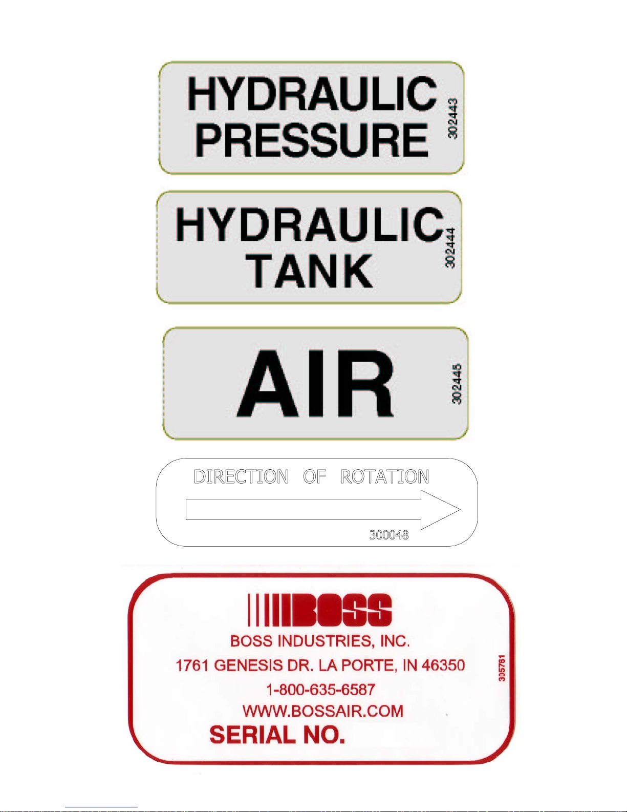
DECAL, DIRECTION OF ROTATION
WASHER, BRASS .585OD X .405ID X .070 THK
LA PORTE, IN 46350
R
DESCRIPTION
1/16
1°
.03
`
`
`
TOLERANCES
ANGULAR
DECIMAL
DO NOT SCALE
FRACTIONAL
UNMACHINED SURFACES
.020
.025
.010
.015
`
`
`
`
NOMINAL DIM.
10.001 & OVER
5.001 TO 10.000
0.000 TO 1.000
1.001 TO 5.000
MACHINED SURFACES
PROPRIETARY INFORMATION
THIS DRAWING AND ALL ITS
CONTENTS ARE P ROPERTY
OF BOSS INDUSTRIES, INC.
AND MUST NOT BE COPIED
OR MADE PUBLIC. IT IS
LOANED AND IS SU BJECT TO
1
SHEET
200353
DWG NO
SCALE
1=8
COMPR & MTG SYS, INFINITY 45 /60/150 SCI8G
08
D
SIZE
11/19/2007
UNLESS NOTED
2
N/A
NDD
CHECKED
DRAWN
PATH
MATERIAL
G:\Inventor Files\200k\200353.dwg
RETURN UPON DEMAND. THE
INFORMATION CONTAINED IN
THIS DRAWING IS
CONFIDENTIAL A ND MUST
NOT BE USED, DIRECTLY OR
INDIRECTLY, IN ANY WAY
DETRIMENTAL TO THE
INTEREST OF BOSS
INDUSTRIES, INC.
302455 15
970512-10617
970608-050310
305624112
300904 115
301722-369117
3
970808-050120
307439125
937806-094233
301593138
300048140
307203141
5
5/22/2008 MCM
3
31
REVISION HISTORY
1
ADDED (2) 307440, (1) 307439. REMOVED (2)
302634, (1) 906030-020, (2) 300033-075.
26
4
REV DESCRIPTION DATE ENG
302636 WAS 6".
1
4
1
24
1
24
1
25
5
10
12
41
37
13
15
14
23
39
19
21
5
20
30
6
10
10
31
35
16
28
11
27
6
6
22
13
29
31
17
7
8
D D
6
32
17
40
18
35
3
4
1
5
36
8
7
34
2
33
9
7
38
8
C C
B B
A A
31
Page 31

1
REV
1 1
OF
BOSS INDUST RIES
1761 GENESIS DR.
1
DESCRIPTIONPART NUMBERQTYITEM
Parts List
2
PANEL, CANOPY BACK-END INFINITY (REV 4)30239211
PANEL, CANOPY HYD END INFINITY (REV 6)302395 12
PANEL, CANOPY AIR END INFINITY30239613
DOOR, CANOPY INFINITY (REV 4)30239414
LATCH, BULLET
HINGE, INFINITY ALUM 3.0" OPEN FACE .18PIN 1/2
KNUCKLE (REV 1)
NUT, TINNERMAN 1/4-20961504-090127BOLT, BTNHD SS STAR-DRIVE 1/4-20 X 3/4983904-075108
WASHER, NYLON 1/4 X .06 X .62
NUT, TINNERMAN 5/16-18961505-140510
BOLT, WHIZLOCK GR5 5/16-18 X 1
WASHER, FLAT GR8 3/8938206-071212
BUMPER, DOOR STOP INFINITY302639213
DECAL, BOSS
DECAL, HYD PRESS LEXAN302443115
DECAL, HYD TANK LEXAN
DECAL, AIR LEXAN302445117
DECAL, OIL DRAIN300913118
DECAL, INFINITY (REV 1)
RIVET, POP 3/16 X 1/2 ALUMINUM943103-0252420
NUT, NYLOC GR5 5/16-18
WASHER, FLAT WIDE 1/4 SS984004-0711022
DECAL, WARNING CONNECT AIR300042123
DECAL, SERIAL TAG BOSS (REV 1)
GROMMET, 1 7/8 OD X 1 1/4 ID X 1/16 THK307433125
CLIP, 1/2" HYD HOSE HOLDER302613226
TAPE, 1/16 X 1/2 CLOSED CELLO3004448 FTNS
30138325
30244216
977004-062109
929705-100711
300649114
302444116
302323119
924305-166221
305761124
3
LA PORTE, IN 46350
R
DESCRIPTION
1/16
1°
.03
`
`
`
TOLERANCES
ANGULAR
DECIMAL
DO NOT SCALE
FRACTIONAL
UNMACHINED SURFACES
.020
.025
.010
.015
`
`
`
`
NOMINAL DIM.
10.001 & OVER
5.001 TO 10.000
1.001 TO 5.000
0.000 TO 1.000
MACHINED SURFACES
PROPRIETARY INFORMATION
THIS DRAWING AND ALL ITS
CONTENTS ARE PROPERTY
OF BOSS INDUSTRIES, INC.
AND MUST NOT BE COPIED
OR MADE PUBLIC. IT IS
LOANED AND IS SU BJECT TO
1
SHEET
200354
DWG NO
SCALE
1=4
CANOPY SYS, INFINITY 45-60-150 SC I8G 08
D
SIZE
12/3/2007
12/3/2007
UNLESS NOTED
2
N/A
NDD
DCL
CHECKED
DRAWN
PATH
MATERIAL
G:\Inventor Files\200k\200354.dwg
RETURN UPON DEMAND. THE
INFORMATION CONTAINED IN
THIS DRAWING IS
CONFIDENTIAL A ND MUST
NOT BE USED, DIRECTLY OR
INDIRECTLY, IN ANY WAY
DETRIMENTAL TO THE
INTEREST OF BOSS
INDUSTRIES, INC.
5/23/2008 MCM
3
1
1
18
25
3
1
20
4
1
26
8
5
REVISION HISTORY
22
11
9
10
REV DESCRIPTION DATE ENG
ADDED (1) 307433, (2) 302613, (2) 943103-025.
UPDATED 302396 TO REV 4.
1
4
19
7
5
20
5
4
13
9
22
6
8
6
6
11
21
12
1
8
22
9
7
20
7
11
7
8
D D
2
9
24
22
8
14
C C
B B
23
15
16
8
17
A A
32
Page 32

1
Parts List
2
DESCRIPTION
COUPLING, PIPE 1/8 GAL 150PSI
PART NUMBER
QTY
13 1 901215-005
14 1 980604-012 CONNECTOR, TUBE 1/4 PAR X 1/8 NPT
ITEM
15 3 300211 RELAY, POWER
16 1 307196 ENCLOSURE, COMPACT RELAY
0
REV
EN Num.
1 1
1761 GENESIS DR.
12
BOSS INDUSTRIES
LA PORTE, IN 46350
R
TITLE
Released For
12/4/2007
12/3/200 7
11
Rev. Date
DCL
Rev. Num.
NDD
DRAWN
CHECKED
THIS DRAWING AND ALL
INFORMATION THEREIN IS
THE PROPERTY OF BOSS
INDUSTRIES, INC., IS CON-
FIDENTIAL AND MUST NOT
BEMADE PUBLIC OR
COPIED. IT IS LOANED
.010
.015
1
9
7
3
6
4
4
5
13
SHEET OF
1
200355-999
DWG NO
ELEC SYS, INFINITY 45-6 0-150 SCI8G 08
C
SIZE
SCALE
MATERIAL
G:\INVENTOR 9.0\
PATH
2
SUBJECT TO RETURN UPON
DEMAND, IS NOT TO BE
USED DIRECTLY OR IN-
DIRECTLY IN ANYWAY DE-
TRIMENTIAL TO THE IN-
TEREST OF BOSS INDUS-
TRIES, INC .
/
.020
14
TOLERANCES
UNLESS NOTED
MACHINED SURFACES NOMINAL DIM.
DO NOT SCALE
0.000 TO 1.000
1.001 TO 5.000
5.001 TO 10.000
10.001 & OVER
8
17 4 931201-050 SCREW, MACH RD HD #8-32 X 1/2
18 4 924301-156 NUT, NYLOC GR5 #8-32
19 1 302678 BRACKET, RELAY HOLDER INFINITY (REV 2)
20 2 929102-050 BOLT, HEX GR5 #6-32 X 1/2
21 1 302780 TIMER, RELAY 12V 30 SEC N.C.
22 2 924200-114 NUT, MACH #6-32
NS 1 307193 HARNESS, WIRING INFINITY 08
NS .083 307190 RELAY, COMPACT 12VDC 30MA
22
19
2
10
20
3
DESCRIPTION
15
16
17
18
21
7
3
8
Parts List
10 1 300076-004 SWITCHGAUGE, TMP 4 ft - 250
11 1 300075 SWITCHGAUGE, PRESSURE
(REV 1)
4
12 1 302591 SWITCH, SHUTDOWN 117LF WITHOUT FUSE
C C
B B
A A
PANEL, GAUGE & LIGHTS INFINITY 08
4
PART NUMBER
5 1 302592 SWITCH, N O MOMENTARY SPST
3 929705-100 BOLT, WHIZLOCK GR5 5/16-18 X 1
6 1 302486 BREAKER, PANEL MTG RESET
7
8 3 961505-140 NUT, TINNERMAN 5/16-18
9 1 307191 DECAL, INFINITY 08 GAUGE PANEL
QTY
1 1 307192
ITEM
2 1 300074 GAUGE, HOURMETER
3 1 302449 LIGHT, INDICATING GREEN
4 2 302450 LIGHT, INDICATING RED
D D
33
Page 33

1
Parts List
DESCRIPTION
BOX, COOLER SHROUD INFINITY (REV 3)
CONTROL
JIC TO SAE
0
REV
EN Num.
1 1
1761 GENESIS DR.
BOSS INDUSTRIES
LA PORTE, IN 46350
R
SHEET OF
1
9
200356-999
DWG NO
OIL-AIR-HYD CLNG SYS, INFINITY SCI8G 08
1
3
TITLE
Released For
12/4/2007
12/3/200 7
Rev. Date
DCL
Rev. Num.
NDD
DRAWN
CHECKED
C
SIZE
SCALE
MATERIAL
G:\INVENTOR 9.0\
PATH
2
THIS DRAWING AND ALL
INFORMATION THEREIN IS
THE PROPERTY OF BOSS
INDUSTRIES, INC., IS CON-
FIDENTIAL AND MUST NOT
BEMADE PUBLIC OR
COPIED. IT IS LOANED
SUBJECT TO RETURN UPON
DEMAND, IS NOT TO BE
.010
.015
PART NUMBER
QTY
ITEM
14 1 302397
15 4 943104-038 RIVET, POP 1/4 X 3/8 ALUMINUM
16 1 300041 DECAL, WARNING FAN GUARD
17 1 970508-106 CONNECTOR, 1/2 MJIC X -12 MSAE
18 4 938604-071 WASHER, FLAT GR5 1/4
19 2 924304-145 NUT, NYLOC GR5 1/4-20
20 2 929104-325 BOLT, HEX GR5 1/4-20 X 3 1/4
21 1 80056-13-12 KIT, HYD VALVE BLOCK 13GPM FLOW
22 1 304700 VALVE, CHECK -12JIC M X -12SAE M FLOW
23 1 306812-282 ORIFICE, BLACK .282 FOR HYD BLOCK
10
.020
1.001 TO 5.000
5.001 TO 10.000
TOLERANCES
UNLESS NOTED
MACHINED SURFACES NOMINAL DIM.
0.000 TO 1.000
DO NOT SCALE
5
13
2
USED DIRECTLY OR IN-
DIRECTLY IN ANYWAY DE-
TRIMENTIAL TO THE IN-
TEREST OF BOSS INDUS-
TRIES, INC .
/
10.001 & OVER
12
6
3
16
2
3
7
14
5
22
DESCRIPTION
3
11
17
Parts List
COOLER, COMPR/HYD/AIR 30 X 16
PUSHER CURVED BLADE
23
8
19
18
21
4
PART NUMBER
QTY
1 1 302570
ITEM
2 1 302087 BULBWELL, 5/8 UNF X 1/2 NPT
3 14 929705-100 BOLT, WHIZLOCK GR5 5/16-18 X 1
D D
2 960108-075 CONNECTOR, 1/2 MJIC X 3/4 MNPT
1 984112-050 ELBOW, HYD 3/4 MNPT X 1/2 MNPT
4 1 302622 FAN ASSY, WITH MOTOR AND GRILL 14.09
5
6 1 960208-050 ELBOW, 1/2 JIC X 1/2 MNPT
7
8 1 907215-020 COUPLING, PIPE 1/2 GAL 150 PSI
9 14 961505-140 NUT, TINNERMAN 5/16-18
10 1 961612-050 NIPPLE, HYD HEX RED 3/4 X 1/2
11 1 960112-075 CONNECTOR, 3/4 MJIC X 3/4 MNPT
12 1 902615-020 ELBOW, PIPE SIDE OUT 1/2 GAL 150PSI
13 1 960212-075 ELBOW, HYD 3/4 MJIC X 3/4 MNPT
C C
18
20
B B
A A
15
4
4
34
Page 34

35
Page 35

RECOMMENDED SP ARE PARTS
REBMUNTRAPNOITPIRCSEDYTQ
1062038ICSRETLIFLIO,TNEMELE1
2517038/7ICSRETLIFRIA,TNEMELE1
0062038ICSNO-NIPS,RECSELAO
C1
306203G8ICSRIAPERLAESTFAHS,TIK1
9417038/7ICSTELNI,EVLAV1
301203GNILPUOCREDIPS1
406203RIAPERLAESTFAHSROTOMDYH,T
IK1
2062038ICSLAMREHT,EVLAV1
36
Page 36

SERVICE QUESTIONNAIRE
DATE :__________
1. Information given by:______________________________________________
2. Information received by:____________________________________________
3. Has anyone helped you: Yes______ No______
4. Distributor:_____________________________________________________
5. End-User:________________________________________________________
6. Phone Number:___________________________________________________
7. Make and Model for PTO:__________________________________________
8. BOSS INDUSTRIES Serial #:_______________________________________
9. Make and Model of Engine:_________________________________________
10. Engine:________________________________________________________
11. Transmission:___________________________________________________
12. Nature of Problem:________________________________________________
___________________________________________________________________________
_______________________________________________________
___________________________________
___________________________________________________________________________________________________________________________________________________________________________________________
_______________________________________________________________________________________________________________________________________________________________________
___________________________________________________________________________________________________________________________________________________
______________________________________________________________________________________________________________________
13. Engine RPM:_____________________________________________________
14. Compressor RPM:________________________________________________
15. Action Taken:_____________________________________________________
______________________________________________________________________________________________________________________________________________________________________________________________________________________
________
_________________________________________________________________________________________
_____________________________________________________________________________________________________________________________________
______________________________________________________________________________________________________________________________________________________________________________________________________________________________
_________________________________________________
__________________________________________________________________________________________________________________________________
Additional Comments:___________________________________________________
______________________________________________________________________
__________________________________________________
____________________________________________________________________________________________________________________________________________________________________________
________________________________________________________________________________________________________________________________________________________
______________________________
________________________________________________________________________________________________________________________________________________________________________________________________
______________________________________________________________________________________________________________________________________________________________________________________________________________________________
___________________________________________________________________________________________
_______________________________________________________________________
______________________________________________________________________________________________________________________________________________________________________________________________________________________________
_______________________________
_______________________________________________________________________________________________________________________________________________________________________________________________
___________________________________________________________________________________________________________________________________
_______________________________________________________________________________________________________________________________________________________
37
Page 37

Instructional Procedures for Installation
of BOSS INFINITY Geared Rot ary Screw Air
Compressor
This air compressor should be installed only by those who have been trained and delegated to
do so and who have read and understand both the operators’ manual and the installation manual.
Failure to follow the instructions, procedures, and safety precautions in this manual may result in
accidents and injuries.
Install, use, and operate this air compressor only in full compliance with all pertinent O.S.H.A.
requirements and all pertinent Federal, S tate, and Local codes or requirements and with BOSS
INDUSTRIES, Inc. instructions.
Do not modify this compressor except with written factory approval.
1. MOUNTING COMPRESSOR
When mounting the compressor care should be taken to ensure that its location does not impede the operation of other components on the vehicle. For example, if your vehicle is equipped
with a crane, you must make sure the compressor will not interfere with the swing of the crane.
In addition, the compressor should be installed in an area that permits cool ambient air to enter
the air filter and the hot air from the cooler to exhaust without recirculating into the air filter. One
last consideration in the mounting should be the routing of hoses and electrical wires. The frame
mounting holes are shown below and the unit should be secured to the vehicle with 3/8 inch
grade 8 bolts, washers should be used on the mounting surface. Hardware supplied with unit,
may not work in all applications.
38
Page 38

INSTRUCTIONAL PROCEDURES
2. INSTALLING THE WIRING & CONNECTING THE HYDRAULIC HOSES
This unit is shipped from the factory with all necessary internal wiring installed. The only remaining wiring necessary is the wiring needed to interface your vehicle/power source with the BOSS
INDUSTRIES compressor . (Please refer to drawing 307193 on page 35) The unit is shipped
with 4 loose wires, they need to be connected as follows:
1. Connect red wire to switched 12 vdc power. (or 24 VDC if you have this option)
2. The yellow wire should be spliced into the 12 vdc switched feed for the on/off switch
per the end-users location.(or 24 VDC if you have this option)
3. Connect black wire to ground.
4. The orange wire is used to activate an electronic speed control circuit if required.
Please contact the factory with engine specific information for further assistance.
CONNECTING THE HOSES
The hydraulic hoses to the compressor should be connected directly to the hydraulic control
block. The pressure “P” input line should be made from a good quality high pressure (min. 3000
PSI) hydraulic hose 1/2” or 3/4” i.d. The return line to tank “T” can be made from a medium
pressure (min. 1000 PSI) hydraulic hose 3/4” i.d. Care should be taken to see that the hoses are
not installed with kinks or bends that inhibit flow of the hydraulic oil. Lack of flow could result in
damage to the motor and compressor. Lastly check to make sure hoses are not in contact with
sharp objects or edges that may fray, chafe or cut them over time. Secure all hoses with tie
down straps or clamps.
39
Page 39

INSTRUCTIONAL PROCEDURES
3. PRE-START-UP INSPECTION CHECKS
This inspection should be done prior to removing truck from bay. Final testing of the system,
including checking for leaks, is to be done outside.
ALL TRUCKS SHOULD BE ROAD TESTED PRIOR TO ST ARTING INST ALLA TION TO ISOLA TE ANY
PREVIOUS TRUCK PROBLEMS.
I. Check sales order to verify that all compressor related items originally ordered have
been installed or are ready to ship with the truck. This would include any special filters,
oils, hoses, options, etc.
II. Vacuum all areas that have metal or plastic shavings. Wipe all fingerprints off unit and
vehicle.
III. Apply decals to proper location. Make sure that the area is cleaned prior to applying
decals. All decals should have a professional appearance upon application.
IV. Check all assemblies, clamps, fittings, drivelines, angles, nuts, and bolts to ensure they
are properly tied and secured to the vehicle. This is a very critical area of inspection.
The vehicle should not be moved until this inspection has been completed.
V. Record all serial numbers for this installation.
A. Vehicle V .I.N.
B. Hydraulic Pump Data
C. Air-End Serial Number
D. BOSS INDUSTRIES Serial Number
E. Receiver Tank Serial Number
F. Note any special applications relating to specific installations.
V I. Check all fluid levels (position the unit on a level surface so that proper amount of fluids
can be added).
A. Fuel to provide for three hours of operation.
B. Transmission fluid and PTO box.
C. Compressor.
Check the compressor oil sump level (see lubricant section of the operator and
parts section for type of lubricant to use). 1. Add oil if needed. 2. Additional oil
may need to be added after test. 3. Top off oil level to half the sightglass when
finished with the test.
D. Any other applicable fluids.
4. INITIAL START-UP AND TEST
A. Start power source and allow for warm-up.
B. Read the operation section in the operator and parts manual carefully before proceeding onto
the initial start-up.
40
Page 40

INSTRUCTIONAL PROCEDURES
C. Engage hydraulic system. A direction of rotation arrow is attached to the compressor pack-
age above the hydraulic coupling. The coupling/hub must be rotating in the direction the
arrow is pointing. If for any reason this arrow has been removed the correct compressor
rotation is clockwise when looking directly at the compressor shaft. Check the direction of
rotation by quickly engaging and then disengaging the compressor.
CAUTION
DO NOT RUN THE COMPRESSOR IN A REVERSE ROTATION FOR PERIODS LONGER
THAN 5 SECONDS. CONTINUED OPERATION IN THIS MANNER WILL RESULT IN
EXTENSIVE COMPRESSOR UNIT DAMAGE.
The safety shutdown switch should be wired in series with the solenoid that opens the flow of
the hydraulic oil to the compressor drive motor. In cases of high temperature and/or pressure,
the closing of the valve will stop the compressor operation.
Safety circuit testing for INFINITY
Safety circuit testing can be done in the following manner. Start the truck. Engage the compressor. Take a screwdriver and touch the 1/16” allen head screw on the face of the temperature gauge and simultaneously touch the outside ring on the face of the gauge. This should shut
off the power to the solenoid of the hydraulics. Push the button in on the shutdown switch to
reset. Repeat the test with the pressure gauge if solenoid does not stop flow to compressor,
check wiring.
41
Page 41

WARRANTY SECTION
42
Page 42

WARRANTY INFORMA TION
BOSS Industries, Inc. warrants that this Rotary Screw Compressor unit conforms to applicable
drawings and specifications approved in writing by BOSS. The unit assembly will be free from
defects in material and workmanship for a period of two (2) years from the date of initial operation
or thirty (30) months from the date of shipment, whichever period first expires. All other components
and parts of BOSS manufacture, will be free from defects in material and workmanship for a
period of one (1) year from the date of initial operation or eighteen (18) months from the date of
shipment, whichever period first expires. If within such period BOSS receives from the Buyer
written notice of and alleged defect in or nonconformance of the unit, all other components and
parts of BOSS manufacture and if in the judgment of BOSS these items do not conform or are
found to be defective in material of workmanship, BOSS will at its option either , (a) furnish a
Service Representative to correct defective workmanship, or (b) upon return of the item F .O.B.
BOSS original shipping point, repair or replace the item or issue credit for the replacement item
ordered by Buyer, (Defective material must be returned within thirty (30) days of return shipping
instructions from BOSS. Failure to do so within specified time will result in forfeiture of claim), or
(c) refund the full purchase price for the item without interest. Factory installed units will also
include warranty on installation for a period of one (1) year . This warranty does not cover damage
caused by accident, misuse or negligence. If the compressor unit is disassembled the warranty is
void. BOSS’s sole responsibility and Buyer’ s exclusive remedy hereunder is limited to such repair,
replacement, or repayment of the purchase price. Parts not of BOSS manufacture are warranted
only to the extent that they are warranted by the original manufacture. BOSS shall have no
responsibility for any cost or expense incurred by Buyer from inability of BOSS to repair under
said warranty when such inability is beyond the control of BOSS or caused solely by Buyer .
There are no other warranties, express, statutory or implied, including those of
merchantability and of fitness of purpose; nor any affirmation of fact or
representation which extends beyond the description of the face hereof.
This warranty shall be void and BOSS shall have no responsibility to repair, replace, or repay the
purchase price of defective or damaged parts or components resulting directly or indirectly from
the use of repair or replacement parts not of BOSS manufacture or approved by BOSS or from
Buyer’s failure to store, install, maintain, and operate the compressor according to the
recommendations contained in the Operating and Parts Manual and good engineering practice.
The total responsibility of BOSS for claims, losses, liabilities or damages, whether in contract or
tort, arising out of or related to its products shall not exceed the purchase price. In no event shall
BOSS be liable for any special, indirect, incidental or consequential damages of any charter, including,
but not limited to, loss of use of productive facilities or equipment, loss of profits, property damage,
expenses incurred in reliance on the performance of BOSS, or lost production, whether suffered
by Buyer or any third party .
BOSS Industries, Inc.
1761 Genesis Drive
LaPorte, IN 46350
43
Page 43

SUMMARY OF MAIN WARRANTY PROVISIONS
As claims, policies and procedure are governed by the terms of the BOSS Industries, Inc. warranty, it is
necessary to outline some of the more important provisions.
The BOSS warranty applies only to new and unused products which, after shipment from the factory, have
not been altered, changed, repaired or mistreated in any manner whatsoever. Normal maintenance items
such as lubricants and filters are not warrantable items.
Parts not of BOSS manufacture are warranted only to the extent they are warranted by the original
manufacturer.
Damage resulting from abuse, neglect, misapplication or overloading of a machine, accessory or part is not
covered under warranty .
Deterioration or wear occasioned by chemical and/or abrasive action or excessive heat shall not constitute
defects.
Parts replacement and/or correction of defective workmanship will normally be handled by BOSS or their
authorized distributor.
Failure to file a detailed warranty claim/service report for each occurrence of material defect of defective
workmanship will cause warranty claim to be rejected.
Defective material must be returned within 30 days of receipt of shipping instructions. Failure to do so
within specified time will result in forfeiture of claim.
The distributor is responsible for the initial investigation and write up of the warranty claim.
Distributor shall be allowed no more than 30 days from date of repair to file a warranty claim/service
report.
W arranty for failure of BOSS replacement parts covers the net cost of the party only, not labor and
mileage.
The BOSS warranty does not cover diagnostic calls and travel. That is time spent traveling to the machine
to analyze the problem and returning with the proper tools and parts to correct the problem.
BOSS will deduct from allowable credits for excess freight caused by sender failing to follow return
shipping instructions.
Distributors or end-users automatically deducting the value of a warranty claim from outstanding balances
due and payable to BOSS prior to receiving written notification of BOSS approval of the warranty claim
may be subject to forfeiture of the entire claim.
44
Page 44

W ARRANTY/RETURN GOODS INSTRUCTIONS
The warranty/return procedure outlined below is provided to give the claimant the information
necessary to file a warranty/return claim, and enable BOSS INDUSTRIES the ability to best serve its’
customers.
Please see the following instructions to initiate a return:
Contact BOSS INDUSTRIES Returns Department by telephone at 219.324.7776 or via email at
service@bossair.com. Y ou may also send a fax at 219.324.7470.
W ARRANTY CLAIMS – PREP ARA TION OF PART RETURN
Parts returned to the factory must be properly packaged to prevent damage during shipment.
Damage to a part as a result of improper handling or packing could be cause for denial. When addressing the package for shipment, the following information must be on the outside of, or tagged clearly , to
the package.
1. Return Goods Authorization #.
2. Distributor or end-users return address.
3. Correct factory address.
4. Number of packages pertaining to each claim.
NOTE: Our warranty requires that all defective parts be returned to BOSS INDUSTRIES freight
prepaid. Items sent without RGA number will not be accepted. Unauthorized Returns Will Immediately
Be Refused At Dock.
RETURN OR WARRANTY CLAIMS – FILING PROCEDURES
1. Initiate through a purchase order for warranty part or request for credit.
2. RGA will accompany replacement part.
3. BOSS INDUSTRIES will confirm disposition of failed part within 30 days of receipt and or
request additional information.
4. Claim denial will result in issuance of a letter of denial.
5. BOSS INDUSTRIES will consider each claim on its’ own merit and reserves the right to accept
or reject claim request. In case of air-ends, these will be returned to the manufacturer for their
analysis/input.
6. Send Warranty Claim to:
BOSS INDUSTRIES, INC.
1761 Genesis Drive
LaPorte, IN 46350
Attn: Returns Dept.
45
Page 45

GENERAL
An approved claim depends on the following provision:
1. An RGA # must be issued by BOSS INDUSTRIES. (See filing procedures.)
2. Failed part must be returned within 30 days of original invoice date, freight prepaid, with RGA
#.
3. Part is determined to be defective.
4. Workmanship is determined to be defective.
5. Machine is within warranty period.
6. Machine has been operated within design conditions.
Claims made through distributors must be verified by distributor prior to contacting BOSS IN-
DUSTRIES.
DAMAGE IN TRANSIT
Do not return damaged merchandise to BOSS INDUSTRIES, please follow claim procedure.
1. Loss in transit:
The merchandise in our kit or provided in our factory installations has been thoroughly inspected or carefully installed and tested before leaving our plant. However, regardless of the
care taken at the factory , there is a possibility that damage may occur in shipment. For this
reason, it is recommended that the unit be carefully inspected for evidence of possible damage
or malfunction during the first few hours of operation. Responsibility for the safe delivery of the
kit or factory installed unit was assumed by the carrier at the time of shipment. Therefore,
claims for loss or damage to the contents of the kit or factory installed unit should be made
upon the carrier.
2. Concealed loss or damage:
Concealed loss or damage means loss or damage, which does not become apparent until the kit
is unpacked or the factory-installed unit is run by the end-user. The contents of the kit or
factory installed unit may be damaged due to rough handling while in route to its destination,
even thought the kit or factory installed unit shows no external damage. When the damage is
discovered upon unpacking, make a written request for inspection by the carrier agent within
fifteen days of delivery date. Then file a claim with the carrier since such damage is the carrier’s
responsibility .
By following these instructions carefully , we guarantee our full support of your claims, to protect
you against loss from concealed damage.
3. Visible Loss or Damage
Any external evidence of loss or damage must be noted on the Freight Bill or Express Receipt,
and signed by the carrier’s agent. Failure to adequately describe such external evidence of loss,
or damage may result in the carrier refusing to honor a damage claim. The carrier will supply
the form required to file such a claim.
46
Page 46

SCREW COMPRESSOR AIR-END EXCHANGE PROGRAM
Replacement air-ends are available from the factory . For current prices and availability , contact
BOSS INDUSTRIES, Inc. or an authorized BOSS INDUSTRIES distributor. Prices are F.O.B.
shipping point. Prices do not include labor for removal or installation.
47
 Loading...