

Boss DD-3A, Boss DD-3B, Digital Delay DD-3, Digital Delay DD-3T Service Notes
SERVICE NOTES
Third Edition
Issued by RJA
Copyright © 2002 ROLAND CORPORATION
All rights reserved. No part of this publication may be reproduced in any form without the written permission
of ROLAND CORPORATION.
Printed in Japan
(0800)
(AS)17059557E3
May 2002
DD-3(T)
SPECIFICATIONS.............................................................2
LOCATION OF CONTROLS,PARTS LIST ...................3
EXPLODED VIEW,PARTS LIST ..................................... 4
PARTS LIST........................................................................5
ADJUSTMENTS ................................................................8
CIRCUIT BOARD..............................................................9
CIRCUIT DIAGRAM......................................................10
WARNING
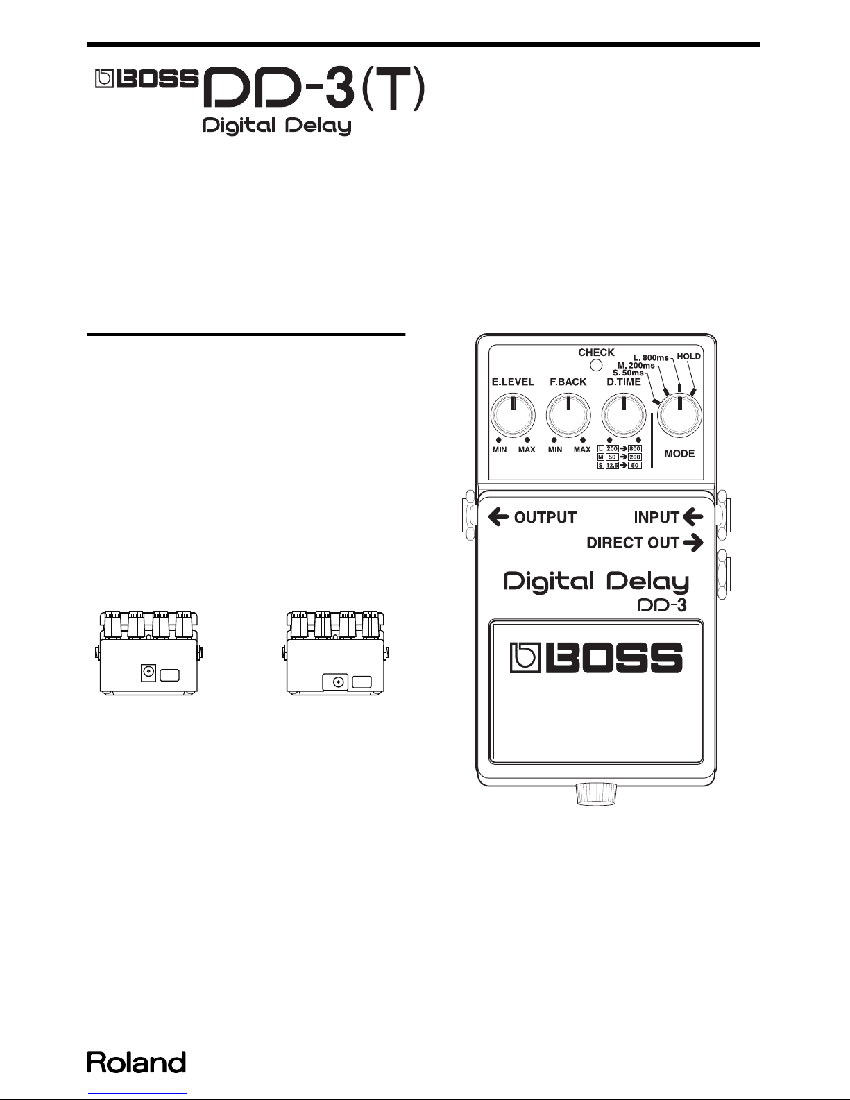
There are three types of DD-3(T) with different circuitry called “DD-3”, “DD3A” and “DD-3B”. The pedals of all three types are labeled “DD-3”.
We call the new type of this model, DD-3B for identifying the old type and
new type for convenience on service system.
Check the model name as follows.
Of the three types, only the appearance of the “DD-3” is different. Identify the
“DD-3” or the “DD-3A or DD-3B” by the shape of the adapter jack as shown in
the following figure.
The appearance of the “DD-3A” and the “DD-3B” are the same. Due to a
DRAM change, it has been changed to “DD-3B” from serial No. SO91200 of
1912LOT (produced in August 2001). It can be identified by the serial number.
The “DD-3A” and “DD-3B” can also be identified by the silk-screen printing
on the board.
When referring to the service notes or ordering parts, check the model name
using the above process.
This service note is for the “DD-3B”. Refer to “DD-3A SERVICE NOTES”
(#17059557) when repairing the DD-3A. Variable resistor, switch and
mechanical parts for the “DD-3A” and “DD-3B” are compatible. Refer to “DD2/3 SERVICE NOTES” (#17059183) when repairing the DD-3.
fig.notice
DD-3A or DD-3B
DD-3

2
May 2002
SPECIFICATIONS
Power Supply
DC 9 V; Dry battery (6AM6/9V)
AC Adaptor (PSA-series: Option)
Current Draw
45 mA to 65 mA (DC 9V)
Controls
Pedal Switch
EFFECT LEVEL
FEEDBACK
DELAY TIME
MODE SELECTOR Switch
Indicator
Check Indicator (serves also as battery check indicator)
Jacks
INPUT
DIRECT OUTPUT
MAIN OUTPUT
AC Adaptor
System
Analog logalithmic compression and 12 bit quantizing system
Delay Time
12.5 ms (MIN) to 800 ms (MAX)
S (Short) 50 ms (12.5 ms to 50 ms)
M (Middle) 200 ms (50 ms to 200 ms)
L (Long) 800 ms (200 ms to 800 ms)
Hold Time
200 ms (MIN) to 800 ms (MAX) in Hold mode
Frequency Response
Delay Sound: 40 Hz to 7 kHz; +1/-3 dB
Direct Sound: 10 Hz to 60 kHz; +1/-3 dB
Residual Noise
-95 dBu (IHF-A, Typ.)
Input Impedance
1 M ohm
Output Load Impedance
10 k ohm or greater
Dimensions
73 (W) x 129 (D) x 59 (H) mm
2-7/8 (W) x 5-1/8 (D) x 2-3/8 (H) inches
Weight
450 g / 1 lb (including battery)
Accessories
OWNER’S MANUAL ENGLISH(#2603768702)
JAPANESE(#2603768603)
Dry Battery(#********); 6AM6/9V (Alkaline)
Leaflet (“USING THE UNIT SAFELY,” “IMPORTANT NOTES,” and
“Information”)
Options
AC Adaptor PSA-Series
*0 dBu = 0.775 Vrms
3
DD-3(T)
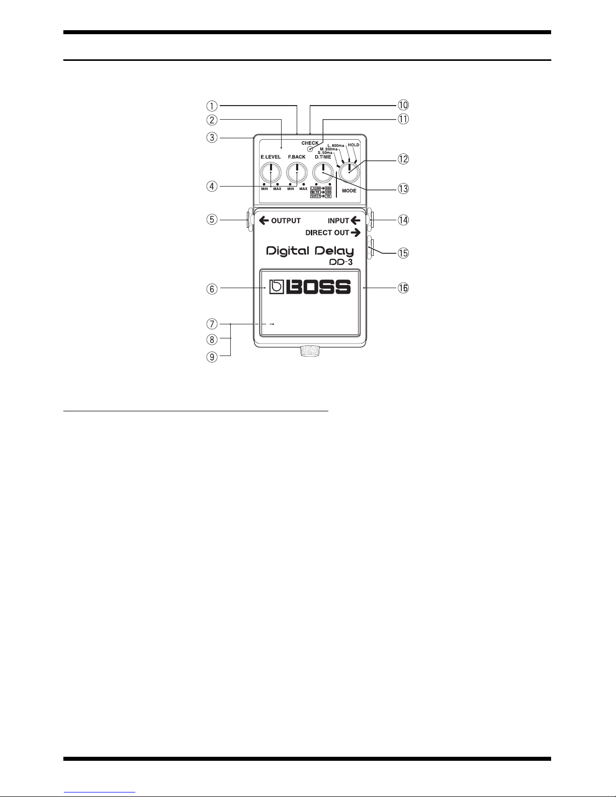
LOCATION OF CONTROLS,PARTS LIST
fig.panel
No.
PART CODE PART NAME DESCRIPTION
1 2253753801 PSA CAUTION 253-538
2 2221740401 PANEL
3 22017993RT CASE
4 2247726200 KNOB (BLUE) 247-262
13279869 POTENTIOMETER RKO971110 50KB
5 13449105MF JACK HTJ-064-14I
6 2235730400 FOOT BASE (PEDAL MAT) 235-304
7 2202785100 BOTTOM COVER 202-851
8 2235730500 BOTTOM BASE 235-305
9 G253751603 BOTTOM CAUTION PSA FCC/CE/C-TICK/EMC GRY
10 13449711 AC ADAPTOR JACK HEC-0470-01-630
11 1502928100 LED (RED) L-34HDSL
12 2247726200 KNOB (BLUE) 247-262
13119308 SWITCH (ROTARY) SBM1024 (SRBM 14011A)
13 2247726200 KNOB (BLUE) 247-262
13289126 POTENTIOMETER RK0971110 10KA 15MM
14 F3449112 JACK (STEREO) HTJ-064-13D
15 13449140MF JACK (STEREO) HTJ-064-14D
16 22187547RT PEDAL
 Loading...