

July.2002
SPECIFICATIONS.............................................................2
EXPLODED VIEW ............................................................ 3
PARTS LIST........................................................................4
TEST MODE....................................................................... 7
CIRCUIT BOARD............................................................10
CIRCUIT DIAGRAM......................................................12
AC ADAPTOR JACK
HEC2392-01-150
Outer
P O-KNOB S BLK/LCG
(22480221)
Inner
P R-KNOB BF BLK/LCG
(22480220)
Pot
"RES, MANUAL"
RD912D-20-20FWH-B54-6009
(F3279854)
Jack HTJ-064-12D
(13449150MF)
(13449717)
PSA CAUTION
(2253753801)
LED (RED)
GL-3ED8
(15029342)
BF-3T
SERVICE NOTES
Issued by RJA
BF-3 PANEL
(G2217155)
BF-3 CASE
(75D643C000)
P R-KNOB MF BLK/LCG
(22480260)
Pot
"DEPTH, RATE"
RD901-20-15FW-B54-006
(F3279852)
"MODE"
RD901-20-15FW-B54-04D
(F3279853)
Jack(GUITAR IN)
2LJ-650NHW00
(F3449150)
Jack(BASS IN)
HTJ-064-140
Bottom Cover
(2202785100)
Bottom Base
(2235730500)
Bottom Caution PSA
(G253751603)
THUMB SCREW
3x10mm(Black)
(H5029820)
(13449140HF)
FOOT BASE
(2235730400)
BF-3 PEDAL
(75D642T000)
Copyright © 2002 ROLAND CORPORATION
All rights reserved. No part of this publication may be reproduced in any form without the written permission
of ROLAND CORPORATION.
17058043E0
Printed in Japan ( 0800 ) (AS)

July.2002
SPECIFICATIONS
BF-3: Flanger
• Nominal Input Level
-20 dBu
• Input Impedance
1 M ohm
• Nominal Output Level
-20 dBu
• Output Impedance
1 k ohm
• Recommended Load Impedance
10 k ohm or greater
• Delay Time
0.3 mS -- 14.4 mS (GUITAR IN)
0.3 mS -- 6.3 mS (BASS IN)
Owner’s Manual English (#G6017305)
Dry battery (9 V type) S-006P/9 V (6F22/9 V)
* The battery that was supplied with the unit is for temporary use-intended
primarily for testing its operation.
• Options
AC Adaptor PSA-Series
* 0 dBu = 0.775 Vrms
* In the interest of product improvement, the specifications and/or appearance of
this unit are subject to change without prior notice.
• LFO Speed
100 mS -- 18 S
• Residual Noise
-95 dBu (IHF-A Typ.)
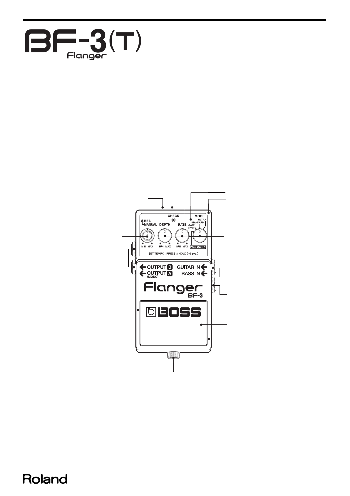
• Controls
Pedal Switch, MANUAL Knob, RES (resonance) Knob, DEPTH Knob,
RATE Knob, MODE Knob
• Indicator
CHECK Indicator (Serves also as tempo and battery check indicator)
• Connectors
GUITAR IN Jack, BASS IN Jack, OUTPUT A (MONO) Jack, OUTPUT B
Jack, AC adaptor Jack (DC 9 V)
• Power Supply
DC 9 V: Dry battery (9 V type) S-006P/9 V (6F22/9 V)
Dry battery (9 V type) 6AM6/9 V (alkaline)
AC Adaptor (PSA-series: optional)
• Current Draw
40 mA (DC 9 V)
* Expected battery life under continuous use:
Carbon: 3 hours Alkaline: 10 hours
These figures will vary depending on the actual conditions of use.
• Dimensions
73 (W) x 129 (D) x 59 (H) mm
2-7/8 (W) x 5-1/8 (D) x 2-3/8 (H) inches
• Weight
420 g /15 oz (including Battery)
• Accessories
2
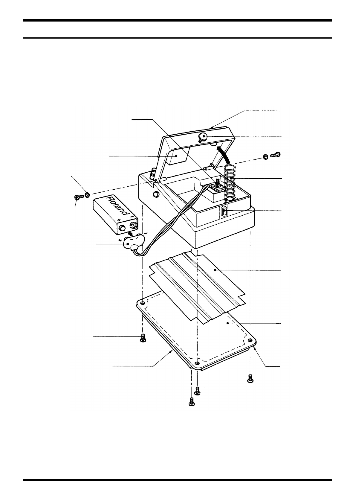
EXPLODED VIEW
fig.bunkai
Cushion
(2226733300)
Switch
JM-0404
(13129710)
BF-3T
Foot Base
(2235730400)
Thumb Screw
3 x 10 (Black)
(H5029820)
Nylon Washer
3 x 6 x 0.5 ( x 2)
(H5039401)
Binding Machine
3 x 10 FeBC ( x 2)
(40010267)
Battery Connector
(F3419102)
Binding Tapping
3 x 6 B1 FeBC ( x 4)
(H5029325)
Spring
(2217710900)
Pedal Guide
Bush
(2215770201)
Insulation
Spacer
(G2167301)
Bottom Cover
(2202785100)
Bottom Caution PSA
(G253751603)
Bottom Base
(2235730500)
3
IC
July.2002
PARTS LIST
fig.part1e
SAFETY PRECAUTIONS:
The parts marked have
safety-related characteristics. Use
only listed parts for replacement.
NOTE: The parts marked # are new. (initial parts)
CASING
2235730400 FOOT BASE (PEDAL MAT) 235-304 1
2202785100 BOTTOM COVER 202-851 1
KNOB,BUTTON
22480220 P R-KNOB (INTERNAL) (SS) BF BLK/LCG 1
22480221 P O-KNOB (EXTERNAL) (OUTER) S BLK/LCG 1
SWITCH
JACK,EXT TERMINAL
13449140MF HTJ-064-14D JACK (STEREO) JK4 1
13449105MF HTJ-064-14I JACK JK5 1
13449717 HEC2392-01-150 ADAPTOR JACK JK1 1
2235730500 BOTTOM BASE 235-305 1
# 75D643C000 CASE 1
# G2217155 PANEL 1
# 75D642T000 PEDAL 1
22480260 P R-KNOB MF BLK/LCG 3
13129710 JM-0404 SWITCH (PUSH) SW1 1
13449150MF HTJ-064-12D PHONE JACK (STEREO) JK2 1
# F3449150 2LJ-650NHW00 GUITAR IN JK3 1
CONSIDERATION ON PARTS ORDRING
When ordering any parts listed in the parts list, please specify the following items in the order sheet.
Failure to completely fill the above items with correct number and description will result in delayed or even
undelivered replacement.
QTY PART NUMBER DESCRIPTION MODEL NUMBER
Ex. 10 22575241 Sharp Key C-20/50
15 2247017300 Knob (orange) DAC-15D
PWB ASSY
02565501 TC220CCA0AF-B01(MR3) IC (DSP) IC5 1
01906156 S-8520E33MC-BJS-T2 IC (DC-DC REGULATOR) IC7 1
15189261 M5218AFP-600E IC (BIPOLAR OP AMP) IC1 1
00346445 NJM2100M(TE3) IC (BIPOLAR OP AMP) IC2 1
02451434 AK4552VT IC (AD/DA) IC4 1
TRANSISTOR
15309104 2SA1586-GR(TE85R) TRANSISTOR Q11,Q12 2
15319108 2SC-3324GR-TE85R TRANSISTOR Q6,Q9 2
15319107 2SC4116-GR(TE85R) TRANSISTOR Q2,Q7,Q10,Q13 4
F5329502 2SJ190 FET Q14 1
15329103T0 2SK880-GR(TE85R) FET Q4 1
DIODE
15029342 GL3ED8 LED LED1 1
15339121 1SS301(TE85R)(CHIP) DIODE DA1,DA2 2
F5339137 SS14 VF=0.45V DIODE D4 1
75D643I000 IN JACK ASSY 1
#
# 75D6439001 MAIN BOARD ASSY 1
# 75D643O000 OUT JACK ASSY 1
02897778 S-80130ALMC-JAP-T2 RESET IC IC8 1
#
# 02898690
# F5329530 FET 2SK879Y FET Q1,Q3,Q5,Q8 4
# F5339201 GS1G DIODE D2,D3 2
MN101C427RH BF-3 V1.00(MASK)
IC (CPU)
IC6 1
RESISTOR
00566867 RPC05T 100 J MTL.FILM RESISTOR R29 1
00567156 RPC05T 102 J MTL.FILM RESISTOR R14,R31,R51,R53 4
00567289 RPC05T 103 J MTL.FILM RESISTOR R8,R13,R18,R25,R28,R35,R45,R47,R60,R61,R
64,R
00567412 RPC05T 104 J MTL.FILM RESISTOR R19,R36,R37,R38,R52 5
4
12

BF-3T
RESISTOR
00567556 RPC05T 105 J MTL.FILM RESISTOR R1,R3,R10,R15,R16,R17,R21,R32,R34,R50,R7111
00567067 RPC05T 221 J MTL.FILM RESISTOR R40,R42 2
00567190 RPC05T 222 J MTL.FILM RESISTOR R46 1
00567323 RPC05T 223 J MTL.FILM RESISTOR R4,R6,R7,R11,R22,R30,R43,R44 8
00567334 RPC05T 273 J MTL.FILM RESISTOR R49 1
00567367 RPC05T 393 J MTL.FILM RESISTOR R41 1
00566967 RPC05T 470 J MTL.FILM RESISTOR R63,R70 2
00567389 RPC05T 563 J MTL.FILM RESISTOR R2,R5,R9,R12,R20,R23,R27,R39 8
F5429365 10K OHM F RANK (1%) CHIP RESISTOR R26 1
F5429386 150K F (1608TYPE) CHIP RESISTOR R24 1
POTENTIOMETER
CAPACITOR
13639546M0 ECEA1CKA100B 10UF/16V CHEMICAL CAPACITOR C8,C9,C12,C13,C17,C20,C22,C25,C26 9
13639550M0 ECEA1CKA101B 100UF/16V CHEMICAL CAPACITOR C30,C37,C40,C44 4
13639549M0 ECEA1CKA470B CHEMICAL CAPACITOR C18,C41,C42,C51 4
13639602M0 ECEA1HKA010B UF 50V CHEMICAL CAPACITOR C1,C10,C11,C23,C24,C28 6
01674701 ECJ1VF1E104Z 0.1UF/16VK CERAMIC CAPACITOR(CHIP) C19,C21,C27,C29,C31,C33,C34,C35,C36,C38
01674512 ECJ1VB1H222K CERAMIC CAPACITOR C2,C5,C14 3
01674689 ECJ1VF1H473Z CERAMIC CAPACITOR C3,C15 2
01674334 ECUV1H101JCV CERAMIC CAPACITOR C4,C7,C16 3
01674467 ECUV1H102JCV CERAMIC CAPACITOR C62 1
01674201 ECUV1H180JCV CERAMIC CAPACITOR C56 1
01674212 ECUV1H220JCV CERAMIC CAPACITOR C57 1
INDUCTOR,COIL,FILTER
F2449209 SLF7032T-151MR29-2(150UH) COIL L3 1
F2449210 SLF7032T-4R7M1R7-2(4.7UH) COIL L2 1
CRYSTAL,RESONATOR
02673278 CX-49G 11.2896MHZ CRYSTAL X1 1
F3279852 RD901-20-15FW-B54-006 POTENTIOMETER VR2,VR3(RATE, DEPTH) 2
#
# F3279853 RD901-20-15FW-B54-04D POTENTIOMETER VR4(MODE) 1
# F3279854 RD912D-20-20FWH-B54-6009 POTENTIOMETER VR1(RES MANUAL) 1
13549329M0 ECQ-B1H104KF3 POLYEST. CAPACITOR C6 1
# 01674690 ECJ1VF1E683Z(1608TYPE) CHIP CAPACITOR C53 1
,C39,
21
WIRING,CABLE
SCREWS
H5029325 SCREW 3X6 PAN HEAD TAPTITE-2 BZC 5
H5039205 WASHER 12.5X9.5X0.5/0.9 INTERNAL TOOTH FENI 4
H5039510 NUT M9X12X2 FENI 4
H5039104 JACK WASHER M9.2X14X1.6 AL 1
22137709 JACK SPACER M9.6X14X1.0 1
H5039112 WASHER M9 4
PACKING
MISCELLANEOUS
G253751603 BOTTOM CAUTION PSA FCC/CE/C-TICK/EMC GRY 1
40016512 INSULOK TIE 80M/M T-18S 2
2226733300 CUSHION 267-333 1
2253753801 PSA CAUTION 253-538 1
2217710900 COIL SPRING 214-109 1
F3419102 BATTERY CONNECTOR 1
G2267201 CUSHION (A) 1
22257257 EARTH TERMINAL ET1,ET2 2
G2167301 INSULATION SPACER 1
#
G3477166 FLAT CABLE 7P-100X6X6 P=2.0 1
# G3477165 FLAT CABLE 3P-70X6X6 P=2.0 1
H5029820 SCREW M3X10 THUMB SCREW 1
# H501941301 SCREW 3X10MM BINDING MACHINE FEBC 2
# H5039401 NYLON WASHER 3X6X0.5 2
40010267 SCREW 3X10 BINDING MACHINE FEBZC 2
G2627738 INNER BOX 1
# G2627141 PACKING CASE 1
F2559702 POLYSWITCH RXE010 R100 1
#
# H2369451 LED SPACER LEDH-5 5MM 3P 1
2215770201 PEDAL GUIDE BUSH 215-702 1
5

July.2002
ACCESSORIES (Standard)
G6017304 OWNER’S MANUAL JAPANESE 1
#
# G6017305 OWNER’S MANUAL ENGLISH 1
6

1.
2.
3.
4.
5.
6.
7.
8.
9.
1.
2.
3.
1.
2.
4.
1.
2.
1.
1.
3.
2.
2.
BF-3T
TEST MODE
Instruments and Other Items
Required
• Oscillator
• Oscilloscope
• Noise meter
• 47 k ohm short-plug
• Monitor speaker
Test Items
DSP, CPU Check
RES Volume Check (LED check included)
MANUAL Volume Check (LED check included)
DEPTH Volume Check (LED check include)
RATE Volume Check (LED check included)
CODEC (DAC) Check (MODE volume and jack-switch checks included)
CODEC (ADC) Lch Check (MODE volume check included)
CODEC (ADC) Rch Check (MODE volume and battery-operation
checksincluded)
Noise Check
How to Enter Test Mode
Set all volume controls at their minimum positions.
Connect a DC plug to the adapter jack while pressing the pedal.
“CHECK” (amber) lights up, and you are in Test mode.
fig.test-dsp_50
500 mV/DIV, 1 mS/DIV
If “CHECK” LED (green) is lit, you are already in the next step of testing.
* If “CHECK” LED (red) blinks, operation stops, and you cannot go to the next
step.Possible causes include defect related to the DSP or CPU, and defective
soldering.Remove the DC plug from the adapter jack, and turn off the power of
the machine.
2. RES Volume Check(LED check
included)
Turn the volume control from the minimum position to the middle and
then to the maximum position clockwise. The “CHECK” LED changes
from green to amber, and then to green.
When the volume control reaches the maximum position, “CHECK”
(green) light up, and the MANUAL volume check starts automatically.
You cannot enter Test mode unless all the volume controls are at their
minimum
positions. You cannot enter Test mode if the minimum values of all the volume
controls are not detected due to some defect or other cause.
As for how to test only a specific item skipping other test items, refer to “5.
How to Test a Specific Item Only” described below after contents of tests are
explained.
Contents of Tests
1. Check of DSP and CPU
Release pedal.
The system checks the DSP and CPU automatically. “CHECK” LED
(green) lights up if no problem is found; “CHECK” (red) blinks if an error
is found.
Check waveforms output from both OUTPUTs A and B on the
oscilloscope.
Input square waves (200 Hz, 1 Vp-p) into GUITAR IN from the oscillator,
and check that the same square waves (200 Hz, 1 Vp-p, DSP through) as
shown in the figure are output.
* The maximum RES volume value and the minimum MANUAL volume value
are detected at the same time.Check the RES volume with the MANUAL volume
control at the minimum position.
3. MANUAL Volume Check (LED check
included)
Turn the volume control from the minimum position to the middle and
then to the maximum position clockwise. The “CHECK” LED changes
from green to amber, and then to green.
When the volume control reaches at maximum position, “CHECK”
(green) lights up, and the DEPTH volume check starts automatically.
The maximum MANUAL volume value and the minimum DEPTH volume
value are detected at the same time. Check MANUAL volume with the DEPTH
volume control at the minimum position.
4. DEPTH Volume Check(LED check
included)
Turn the volume control from the minimum position to the middle and
then to the maximum position clockwise. The “CHECK” LED changes
from green to amber, and then to green.
When the volume control reaches the maximum position, “CHECK”
(green) lights up, and the RATE volume check starts automatically.
The maximum DEPTH volume value and the minimum RATE volume value
are detected at the same time. Check DEPTH volume with the RATE volume
control at the minimum position.
7

July.2002
1.
1.
2.
3.
4.
5.
7.
8.
1.
2.
3.
4.
5.
1.
2.
2.
6.
3.
5. RATE Volume Check(LED check
included)
Turn the volume control from the minimum position to the middle and
then to the maximum position clockwise. The “CHECK” LED changes
from green to amber, and then to green.
When the volume control reaches the maximum position, “CHECK “
(green)lights up.
6. CODEC (DAC) Check(Check of MODE
volume and jack-switch included)
Position MODE volume at “GATE/PAN”.
Check that “CHECK” LED (amber) is lit.
Connect a plug to GUITAR IN. (Waves are output even if no signal is
input.)
Check the waveforms output from both OUTPUTs A and B on the
oscilloscope.
Check that the output waveforms are the same square waves (200 Hz, 1
Vp-p) as those shown in the figure.
fig.test-dac_50
Check that the output waveforms are the same step-like waves (1Vp-p) as
those shown in the figure.
fig.test-mono_50
500 mV/DIV, 1 mS/DIV
7. CODEC (ADC) Lch Check (MODE
volume check included)
Set MODE volume at “STANDARD”.
Check that “CHECK” LED (green) is lit.
Input 1kHz, -20dB sine waves into BASS IN from the oscillator.
Check the waveforms output from both OUTPUTs A and B on the
oscilloscope.
Check that the output waveforms are the same as those shown in the
figure.
500mV/DIV, 1mS/DIV
To check the GUITAR IN jack-switch, remove the plug from GUITAR IN
and connect it to BASS IN.
Check the waveforms output from both OUTPUTs A and B on the
oscilloscope.Check that the output waveforms are the same square waves
(400 Hz, 1 Vp-p) as those shown in the figure.
fig.test-bassin_50
500 mV/DIV, 1 mS/DIV
To check the OUTPUT B jack-switch, remove the plug from OUTPUT B.
Check the waveforms output from OUTPUT A on the oscilloscope.
fig.test-lch_50
OUTPUT A : 50mV/DIV, OUTPUT B : 500mV/
DIV, 1mS/DIV
Measure the output levels of both OUTPUTs A and B with a noise meter
(JIS-A).
Check that the output from OUTPUT A is between -22.5 dbm and -20.5
dBm, and the output from OUTPUT B is -100 dBm or lower.
8. CODEC (ADC) Rch Check(Check of
MODE volume and battery operation
included)
Set MODE volume at “ULTRA”.
Check that “CHECK” LED (amber) is lit.
Input 1kHz, -20dB sine waves into BASS IN from the oscillator.
8

4.
5.
8.
9.
1.
6.
7.
9.
1.
1.
2.
2.
3.
4.
5.
6.
7.
8.
3.
BF-3T
Check the waveforms output from both OUTPUTs A and B on the
oscilloscope.
Check that the output waveforms are the same as those shown in the
figure and that they are not distorted.
fig.test-lch_50
OUTPUT A : 50 mV/DIV, OUTPUT B : 500 mV/
DIV, 1mS/DIV
Measure the output levels of both OUTPUTs A and B with a noise meter
(JIS-A).
Check that the output levels are the same as those shown in Test Item 7
above.
Remove the DC plug quickly from the adapter jack, and check battery
operation.
How to Exit Test Mode
Press the pedal to exit Test mode.
During volume checks 2 through 5, however, you exit volume check if
you press the pedal.
Press the pedal again to exit Test mode.
If an error is found during the DSP or CPU check mentioned in Test Item 1
above, you cannot exit Test mode by pressing the pedal. Remove the DC plug
from the adapter jack, and turn off the power of the machine.
The noise check mentioned in “9. Noise check” above is not done in
Test mode, it is done in Normal mode.
How to Test a Specific Item Only
Enter Test mode.
Release pedal. The system checks the DSP and CPU automatically as
mentioned in “1. Check of DSP and CPU” above. The “CHECK” LED
(green) light up if no problem is found.
Choose the next test item you want with MODE volume.
MOMENTARY: 2. - 5. Volume check
GATE/PAN: 6. CODEC(DAC)check
STANDARD: 7. CODEC(ADC)L ch check
ULTRA: 8. CODEC(ADC)R ch check
Remove the plug quickly, or the machine will be reset. If the machine is reset
every time you remove the plug, the adapter jack contact or some other part
may be defective.
Check that the same waveforms are output and that “CHECK” LED (red)
is lit.
If the battery is exhauted, LED will light up gloomily.
Check again that the output waveforms are not distorted.
Remove the plug from BASS IN, and check that the “CHECK” LED goes
out with no waveforms shown (power off).
9. Noise Check
Connect a DC plug to the adapter jack, and a 47 k? short-plug to GUITAR
IN.
Set all the volume controls at to their maximum positions.
Check that “CHECK” LED (red) is lit.
Measure the residual noise of both OUTPUTs A and B with a noise meter
(JIS-A).
Check that the noise is -92 dBm or lower.
Press the pedal to turn off the “CHECK” LED (to form a bypass).
Measure the residual noise of both OUTPUTs A and B with a noise meter
(JIS-A).
Check that the noise is -100 dBm or lower.
Connect a monitor speaker to OUTPUT.
Drop the machine twice from a height of 10 cm to apply it shock.
Check that no abnormal noise occurs.
Turn the pedal on and off and turn each volume control, then check that
no abnormal noise occurs.
You can only do a volume check in the following order: RES -> MANUAL ->
DEPTH -> RATE.
If you do the noise check mentioned in “9. Noise check” above, don’t enter Test
mode, but do it in Normal mode after turning on the power of the machine.
Be sure to check all the test items before you ask for repair or when you check
and service the machine.
9

July.2002
CIRCUIT BOARD
View from components side
View from foil side
10

BF-3T
11

July.2002 BF-3T
CIRCUIT DIAGRAM
fig.mainboard
GUITAR IN
JK3
2LJ-650NHW00
BASS I N
2
3
1
JK4
HTJ-064-14D
6
7
4
8
3
2
9
BRN
BLK
BT1
6F22
006P
C1
1/50
+
C18
47/16
A
+
84
-
IC1C
M5218AFP
+
A
C2
R4
0.0022
22k
C4 100p
10/16
C8
22k
6
-
5
A4V
+
+
IC1B
M5218AFP
R22
22k
C14
0.0022
C10
1/50
7
+
R9 56k
R11
C16 100p
R27 56k
R30
C22
22k
10/16
C29
0.1
A
C35
C34
C36
0.1
44
45
46
47
48
50
51
53
27
28
29
30
34
35
36
37
41
40
39
76
55
1
3
6
5
25
42
72
C33
0.1
0.1
0.1
CA4
CA3
CA2
CA1
CA0
RD
WR
D
CD7
CD6
CD5
CD4
CD3
CD2
CD1
CD0
R70
47
D
+
D3.3
C62
0.001
2
-
3
A4V
+
+
IC1A
M5218AFP
D
R50
1M
R51
1k
C56
C57
22p
18p
DD
1
X1
49US SMD
11.2896MHz
R39
56k
R41
39k
R38
100k
C23
1/50
A9V
+
+
D3.3
CD7
CD6
CD5
CD4
CD3
CD2
CD1
CD0
+
D3.3
+
D
C58
0.1
D
+
D3.3
84
IC2C
A4V
+
-
+
C43
N.I.U
+
D3.3
D
C51
47/16
D
NJM2100M
C26
10/16
C12
10/16
C17
10/16
C59
0.1
DA
AD
BCLK
LRCK
MCLK
+
D3.3
R49 2 7k
C31
0.1
C53 0 .0 68
D3.3
C27
0.1
D
AD
DA
LRCK
MCLK
BCLK
57
DA0
58
AD0
60
BCK
62
LRCK0
63
LRCK1
65
MCK
67
R63
DA1
68
47
AD1
69
DA2
70
AD2
74
DA3
75
AD3
D
78
TESTT
32
TESTS
77
TESTB
13
TESTP
10
PLLBP
D
15
VDD
16
PLLVAA
17
PLLRO
18
PLLLP
19
PLLAGS
20
PLLAGD
21
VSS
+
9
DIVS1
8
DIVS0
DSP (MR3)
IC5
TC220CCA0AF-B01(MR3)
D3.3
R29
10
5
VD
2
LIN
AD/DA
1
RIN
6
DEMO
7
DEM1
8
SDTO
9
SDTI
10
LRCK
11
MCLK
12
BCLK
13
PDN
3
D
+
D3.3
56
59
64
73
79
VDD
VDD
VDD
VDD
VSS
VSS
VSS
VSS
VSS
VSS
43
52
54
61
66
71
80
RESET
DS1VDD
2
VSS
3
NC
IC8
D
S-80130ALMC-JAP-T2
+
C19
0.1
4
VA
15
LOUT
16
ROUT
14
VCOM
C28
38
26
OUT
24
33
VDD
VDD
VSS
VSS
12
22
IC4
AK4552VT
C38
0.1
7
14
VDD
VDD
VDD23VDD
INT1
INT0
DRQ
OSC
OSCSEL
DRST
CTYPE
VSS
VSS
VSS11VSS
2
4
D
+
D3.3
5
4
1/50
CA4
CA3
CA2
CA1
CA0
RD
CS
WR
CD7
CD6
CD5
CD4
CD3
CD2
CD1
CD0
SYI
DIV
XTI
XTO
RST
VSS
A
49
VDD
VDD
VSS
VSS
31
A8V
+
DA3
N.I.U
21
3
3
+
R10
1M
Q4
2SK880GR
C9
10/16
1 2
R13
10k
A
BRN
BLK
YEL
1
2
R8
10kC60.1(P)
A
A
19
BLUORG
+
D3.3
R25
10k
R28
C20
10k
BLK
12
JK1
HEC2392-01-150
AC
ADAPTOR
RED
16
ET1
ET2
+
D3.3
R64
R69
10k
10k
*2
C32
NFM4516P13C204F
2
3
1
5
4
A
L2
SLF7032T-4R7M1R7-2 4.7uH
D DD
C44
100/16
EARTH_TERMINAL (RV-2)
EARTH_TERMINAL (RV-2)
DA
D D
R100
RXE010
D2
GS1G
D3
GS1G
A
C45
0.1
D
DC/DC
Converter
10/16
D
A9V
+
C40
100/16
5
VIN
1
ON/OFF
2
VSS
IC7
S-8520E33ML-BJS
C21
0.1
VOUT
R6
C5
0.0022
R12
56k
Q13
2SC4116GR
R46
2.2k
C39
0.1
C41
47/16
Q14
2SJ190
1
4
EXT
3
R7
22k
22k
C7
100p
6
7
5
+
IC2B
NJM2100M
C61
N.I.U
R24
150kF
R26
10kF
2
-
3
+
IC2A
NJM2100M
+
A8V
23
R45
1
23
10k
R47
10k
C37
100/16
L3
SLF7032T-151MR37-2 150uH
D4
SS14
+
D3.3
C30
100/16
C55
0.1
DD
1
C42
47/16
(PCB G2927207 01 1/5)
*10kF,150kF=+/-1% 0603 Type Chip Resistor
*1:MN101CP427BF(R02891234):1LOT - 5LOT
MN101C427RH (R02898690):6LOT
*2:NFM4516P13C204F:1LOT
BF-3 MAIN BARD ASSY 75D6439000
( PCB G2927207 1/5)
R1
1M
R15
1M
R32
1M
Q10
2SC4116GR
1
LED-RED
LED-GRN
+
D3.3
41
42
43
44
37
36
35
34
33
32
31
30
29
28
27
13
16
17
*1
Q1
2SK879Y
Q3 2SK879Y
Q5
2SK879Y
Q8
2SK879Y
23
R37
100k
P87/LED7
P86/LED6
P85/LED5
P84/LED4
1
LED3/P83
2
LED2/P82
3
LED1/P81
4
LED0/P80
P67
P66
P65
P64
P63
P62
P61
P60
P22/IRQ2
P21/IRQ1/SENS
P20/IRQ0
VDD
VSS
NC
IC6
MN101C427
12
3
DA1
1SS301
3
1 2
3
12
12
3
DA2
1SS301
3
1 2
3
12
Q11
2SA1586GR
R43
22k
EFFECT-ON
EFFECT-OFF
R3
1M
C3
0.1
R21
1M
C15
0.1
A
32
1
TXD/SBO0/P00
RXD/SBI0/P01
CPU
+
R2
56k
2 3
DA
+
R20
56k
2 3
D
Q12
2SA1586GR
1
R44
22k
AN7/PA7
AN6/PA6
AN5/PA5
AN4/PA4
AN3/PA3
AN2/PA2
AN1/PA1
AN0/PA0
SBT0/P02
BUZZER/P06
RMOUT/P10
P14/TM4IO
P13/TM3IO
P12/TM2IO
P27/NRST
OSC2
OSC1
MMOD
Q2
2SC4116GR
1
Q7
2SC4116GR
1
32
P11
P70
R5
56k
R23
56k
12
11
10
9
8
7
6
5
18
19
20
21
22
26
25
24
23
38
39
14
15
40
OUT-SW
MANUAL
RES
DEPTH
RATE
MODE
EXT-TI P
EXT-RI NG
+
C11
1/50
++
R71
1M
C24
1/50
R60
10k
C72
N.I.U
+
+
D3.3
R61
10k
R40
220
R42
220
+
D3.3
D3.3
R66
N.I.U
C66
N.I.U
R65
N.I.U
D
C47
C46
C65
0.1
0.1
N.I.U
DD
+
R16
1M
WR
RD
CA0
CA4
CA3
CA2
CA1
C63
C64
0.1
N.I.U
X2
N.I.U
C71
N.I.U
D
Q6
2SC3324GR
1
C13
R14
10/16
C25
10/16
R19
100k
1k
A
R31
1k
R36
100k
A
2 3
R17
1M
R18
10k
A
+
Q9
2SC3324GR
1
2 3
R34
1M
R35
10k
A
WHT
3
GLY
4
ORG
5
6
7
8
+
D3.3
D
20
1
1
21
15
9
10
11
12
13
+
R67
N.I.U
R68
N.I.U
C50
0.1
C49
C48
0.1
0.1
14
+
D3.3
R52
100k
D
R53
1k
BYO
17
18
GRN
D
OUTPUT A (MONO)
2
4
1
OUTPUT B
4(20)
2
3
1
5(21)
(RED/GRN)
6
RED
GRN
7
8
(PCB G2927207 5/5)
+
D3.3
15
9
2
10
11
2
12
13
2
2
2
14
D
17
18
(PCB G2927207 4/5)
JK5
HTJ-064-14I
JK2
HTJ-064-12D
JACK BOARD
(PCB G2927207 3/5)
LED BOARD
LED1
1 2
CHECK
3
GL3ED8
VR BOARD
(PCB G2927207 2/5)
+
D3.3
3
MANUAL
VR1-A
RD912D-20-20FWH-B54-6009
50kB
1
or RK0972210
D
+
D3.3
3
RES
VR1-B
RD912D-20-20FWH-B54-6009
50kB
1
or RK0972210
D
+
D3.3
3
DEPTH
VR2
RD901-20-15FW-B54-006
1
D
+
D3.3
3
RATE
VR3
RD901-20-15FW-B54-006
1
D
+
D3.3
3
MODE
VR4
RD901-20-15FB-B54_04
1
D
1 2
SW1
JM-0404
SW BOARD
13
 Loading...