

Boss BF-3A, BF-3T Service Manual
Jun. 2011 BF-3(T)
SERVICE NOTES
Issued by RJA
Table of Contents
Identifying the BF-3(T) .....................................................2
Cautionary Notes ..............................................................2
Specifications .....................................................................3
Location of Controls .........................................................4
Exploded View ..................................................................5
Disassembly Procedure ....................................................6
Conversion to the BF-3A ..................................................6
Parts List .............................................................................7
Verifying the Version........................................................9
Data Backup and Restore Operations ............................9
Performing a Factory Reset..............................................9
Updating the System ........................................................9
Test Mode ...........................................................................9
Circuit Board (Main, VR, LED, SW, Output B
Board)................................................................................12
Circuit Diagram (Main, VR, LED, SW, Output B
Board)................................................................................14
Copyright © 2011 Roland Corporation
All rights reserved. No part of this publication may be reproduced in any form without the written permission
of Roland Corporation.
CC-KWS17058043E1

Jun. 2011 BF-3(T)
Identifying the BF-3(T)
The BF-3(T) exists in two types that have different circuit structures. In this
Service Notes, the older type is called the BF-3, and the newer type is called
the BF-3A. Both have Flanger BF-3 inscribed on the pedal and appear at a
glance to be completely identical, but they can be distinguished as indicated in
the following table.
Production number Up through
Style of component mounting
on the circuit board
System version Version 1.00 Version 2.00 or later
After identifying the type of the product being serviced, refer to the
corresponding Service Notes for information on required parts and test
methods.
BF-3: SERVICE NOTES (#17058043E0)
BF-3A: SERVICE NOTES 2ND EDITION (#17058043E1)
This version of Service Notes is for the BF-3A.
BF-3 BF-3A
H**8559
Single-side
mounting
H**8560 and after
Double-side
mounting
Cautionary Notes
Before beginning the procedure, please read
through this document. The matters described may
differ according to the model.
User Data Cannot Be Backed Up
The setting for the sleep mode is saved on the Main Board even when the
power has been switched off, but neither verification of its status (ON or OFF)
nor backing up the setting is possible. When the Main Board has been
replaced, the sleep mode is returned to its default (ON). For more information
about the sleep mode, refer to About Sleep Mode (Owner’s Manual, p. 14).
No user data other than the setting for the sleep mode is saved.
Part Replacement
When replacing components near the power-supply circuit or a heatgenerating circuit (such as a circuit provided with a heat sink or including a
cement resistor), carry out the procedure according to the instructions with
respect to the part number, direction, and attachment position (mounting so as
to leave an air gap between the component and the circuit board, etc.).
Parts List
A component whose part code is ******** will not be supplied as a service part
because one of the following reasons applies.
• Because it is supplied as an assembled part (under a different part code).
• Because a number of circuit boards are grouped together and supplied as
a single circuit board (under a different part code).
• Because supply is prohibited due to copyright restrictions.
• Because reissuance is restricted.
• Because the part is made to order (at current market price).
• Because it is carried in electronic data on the Roland web site.
• Because it is a package or an accessory irrelevant to the function
maintenance of the main body.
• Because it can be replaced with an article on the market. (battery or etc.)
Circuit Diagram
In the circuit diagram, “NIU” is an abbreviation for “Not in Use,” and
“UnPop” is an abbreviation for “Unpopulated.” They both mean non-mounted
components. The circuit board and circuit board diagram show silk-screened
indications, but no components are mounted.
2

Jun. 2011 BF-3(T)
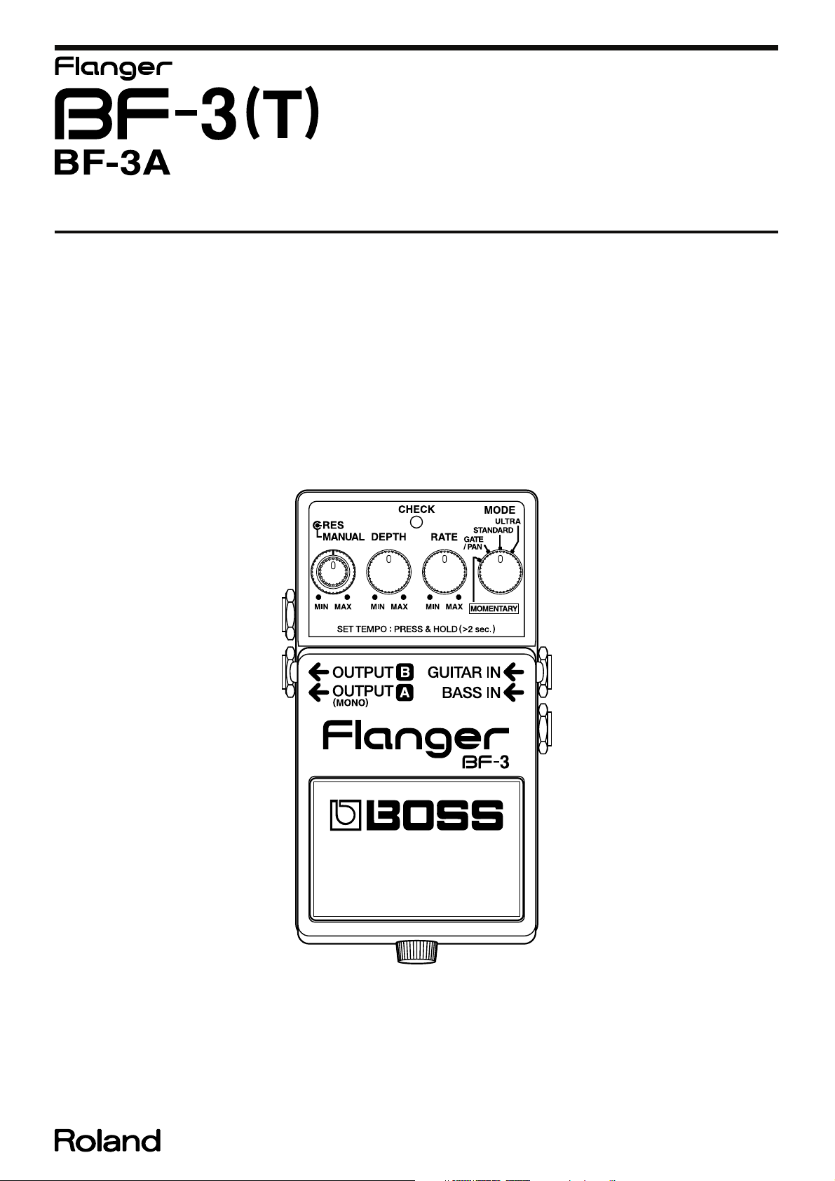
Specifications
BF-3: Flanger (BF-3A)
Nominal Input Level
-20 dBu
Input Impedance
1 MΩ
Nominal Output Level
-20 dBu
Output Impedance
1 kΩ
Recommended Load Impedance
10 kΩ or greater
Delay Time
0.3 mS–14.4 mS (GUITAR IN)
0.3 mS–6.3 mS (BASS IN)
LFO Speed
100 mS–18 S
Residual Noise
-95 dBu (IHF-A Typ.)
Power Supply
DC 9 V;
Dry battery 6F22 (9 V) type (carbon)/Dry battery 6LR61 (9 V) type (alkaline)
AC Adaptor (PSA-series: optional)
Current Draw
40 mA (DC 9 V)
* Expected battery life under continuous use:
Carbon: 3 hours
Alkaline: 10 hours
These figures will vary depending on the actual conditions of use.
Dimensions
73 (W) x 129 (D) x 59 (H) mm
2-7/8 (W) x 5-1/8 (D) x 2-3/8 (H) inches
Weight
435 g /1 lb (including Battery)
Accessories
Owner’s Manual (#5100021063)
Leaflet (“USING THE UNIT SAFELY,” “IMPORTANT NOTES,” and
“Information”) (#********)
Dry battery/9 V type (6F22) (#********)
* The battery that was supplied with the unit is for temporary use intended
primarily for testing its operation.
Controls
Pedal Switch
MANUAL Knob
RES (resonance) Knob
DEPTH Knob
RATE Knob
MODE Knob
Indicator
CHECK Indicator (Serves also as tempo and battery check indicator)
Connectors
GUITAR IN Jack
BASS IN Jack
OUTPUT A (MONO) Jack
OUTPUT B Jack
AC adaptor Jack (DC 9 V)
Options
AC Adaptor PSA-series
* 0 dBu = 0.775 Vrms
* Printed matters will not be supplied after the end of the production. Then,
download the electronic file from the Roland web site.
* In the interest of product improvement, the specifications and/or appearance of
this unit are subject to change without prior notice.
3
Jun. 2011 BF-3(T)
Location of Controls
fig.panel.eps
16
17
18
No. Part Code Part Name Description Q’ty
1 5100014487 COMPACT PSA LABEL (22537538R0) 1
2 5100021036 PANEL 1
3 5100021031 CASE 1
4 22480220 P R-KNOB (INTERNAL) (SS) BF BLK/LCG 1
22480221 P O-KNOB (EXTERNAL) (OUTER) S BLK/LCG 1
5100018911 ROTARY POT(F3229220R0) RD912DF-20-20FWH-B50K-60009A2 1
40128923 HEX NUT M7 1
5 5100001341 6.5MM JACK HTJ-064-12DMP (13449150R1) 1
5100003926 PLAIN WASHER 9X13.5X0.5T NI(H5039158R0) 1
5100008086 INT TOOTH WASHER 9.5X12.5X0.5 NI RTC(H5039205R0) 1
5100003918 JACK NUT M9X12X2 NI RTC(H5039510R0) 1
5100015893 PLAIN WASHER 9.2X14X1.6 NI (H5039104R0) 1
5100015900 PLAIN WASHER 9.6X14XW11X1.0 AL (22137709R0) 1
6 13449105R0 6.5MM JACK HTJ-064-14I 1
5100003926 PLAIN WASHER 9X13.5X0.5T NI(H5039158R0) 1
5100008086 INT TOOTH WASHER 9.5X12.5X0.5 NI RTC(H5039205R0) 1
5100003918 JACK NUT M9X12X2 NI RTC(H5039510R0) 1
7 5100008294 PEDAL PLATE (22357304R0) 1
8 5100006632 BOTTOM COVER (22027851R0) 1
9 5100006633 BOTTOM FOOT (22357305R0) 1
10 5100006631 CAUTION SEAL PSA (FCC/EMI)(G2537516R2) 1
11 5100007512 THUMB SCREW (H5029820R0) 1
12 F3439875R0 ADAPTOR JACK KM02018ABM1P 1
13 F5029423R0 LED L-3VEGW 1
5100002339 LED SPACER 304 1
14 04567601 P R-KNOB MF BLK/LCG(22480260R0) 1
5100014193 R.POTENTIOMETER (F3279853R0) RD901F-20-15FB-B50K-04 1
40128923 HEX NUT M7 1
15 04567601 P R-KNOB MF BLK/LCG(22480260R0) 2
F3279852R0 POTENTIOMETER RD901-20-15FW-B54-006 2
40128923 HEX NUT M7 2
16 5100020609 6.5MM JACK SCJ614M2NCS3B11G 1
5100003926 PLAIN WASHER 9X13.5X0.5T NI(H5039158R0) 1
5100008086 INT TOOTH WASHER 9.5X12.5X0.5 NI RTC(H5039205R0) 1
5100003918 JACK NUT M9X12X2 NI RTC(H5039510R0) 1
17 5100006457 6.5MM JACK HTJ-064-14D(13449140R0) 1
5100003926 PLAIN WASHER 9X13.5X0.5T NI(H5039158R0) 1
5100008086 INT TOOTH WASHER 9.5X12.5X0.5 NI RTC(H5039205R0) 1
5100003918 JACK NUT M9X12X2 NI RTC(H5039510R0) 1
18 5100021035 PEDAL 1
4
Jun. 2011 BF-3(T)
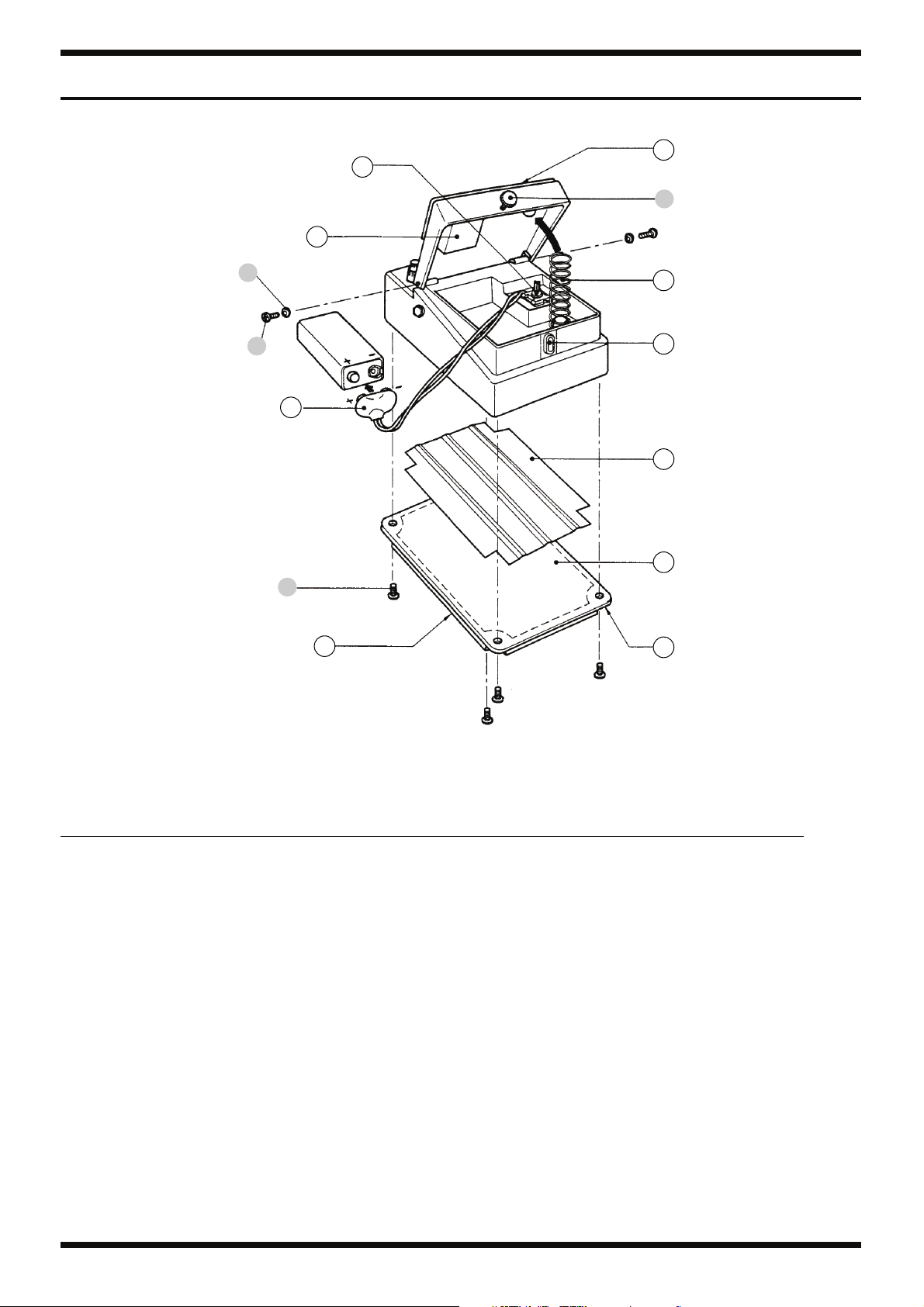
Exploded View
fig.bunkaizu.eps
10
1
d
2
a
b
9
8
3
7
6
c
4
5
No. Part Code Part Name Description Q’ty
1 13129710R0 SWITCH(PUSH) JM-0404 1
2 5100007503 BATTERY CUSHION (22267333R0) 1
3 5100007872 BATTERY CONNECTOR 006P BATTERY SNAP (F3419102R0) 1
4 5100006631 CAUTION SEAL PSA (FCC/EMI)(G2537516R2) 1
5 5100006633 BOTTOM FOOT (22357305R0) 1
6 5100006632 BOTTOM COVER (22027851R0) 1
7 5100022073 INSULATING SHEET 1
8 5100007505 PEDAL GUIDE BUSH (22157702R0) 1
9 5100007504 COIL SPRING (22177109R0) 1
10 5100008294 PEDAL PLATE (22357304R0) 1
a 5100008092 PLAIN WASHER 3X6X0.5 RESIN RTC(H5039708R0) 2
b 40010267 SCREW M3X10 BINDING MACHINE FE BZC 2
c 5100007965 SCREW 3X6(H5029325R0) PAN TAPPING B1 BZC 4
d 5100007512 THUMB SCREW (H5029820R0) 1
5
 Loading...