

Page 1
Lifestyle® PS 18, 28 and 48
AMP PCB, Assebly 267332-0, Bare PCB - 267331-001
Digital Acoustimass
100V, 120V, 230V, Dual Voltage
®
Powered Speakers
Lifestyle® 28 Home Theater System
5 Double Cube Speakers
PS28 bass module
Lifestyle® 35 Home Theater System
5 Jewel Cube
PS48 bass module
®
Speakers
Power PCB, Assembly - 260327-001, Bare PCB - 266459-001
AMP PCB, Assembly - 266999-0, Bare PCB - 267083-001
DSP PCB, Assembly - 267391-0, Bare PCB - 267086-001
Service Manual
©2008 Bose Corporation
Lifestyle
®
18 Home Theater System
5 Single Cube Speakers
PS18 bass module
Reference Number 268795-SM
Rev 13
Electronic copy only
Page 2

PS18/28/48 Service Manual
Contents
Safety Information.............................................................................................................................2
Electrostatic Discharge Sensitive Device Handling (ESDS) .........................................................2
Specifications ....................................................................................................................................3
Part List Notes ...................................................................................................................................4
Part List Table of Contents ............................................................................................................... 4
Lifestyle® 18 Home Theater System Packaging.............................................................................. 5
Figure 1. LS18 System Packaging Exploded View ..............................................................................5
Lifestyle
Figure 2. LS28 System Packaging Exploded View ..............................................................................6
Lifestyle® 35 Home Theater System Packaging.............................................................................. 7
Figure 3. LS35 System Packaging Exploded View ..............................................................................7
Lifestyle® 18/28/35 Essentials Kit Part List ..................................................................................... 8
Figure 4. LS18, 28, 35 Essentials Kit Exploded View.......................................................................... 9
Lifestyle
Lifestyle
Lifestyle
Lifestyle
Lifestyle
Lifestyle
Figure 5. LS18, 28 Cube Pack Exploded View ..................................................................................12
Figure 6. LS35 Cube Pack Exploded View ........................................................................................ 12
Jewel Cube Part List ....................................................................................................................... 13
Figure 7. Jewel Cube Exploded View ................................................................................................ 13
Single and Dual Cube Speaker Part List ....................................................................................... 14
Figure 8. Cube Exploded View .......................................................................................................... 14
PS18/28/48 Bass Module Assembly Part List ............................................................................... 15
Figure 9. Bass Module Exploded View.............................................................................................. 15
PS18/28/48 Amplifier Module Assembly Part List........................................................................16
Figure 10. Amplifier Module Exploded View...................................................................................... 16
PS18/28/48 Electrical Part List ................................................................................................. 17-31
Setting up a computer to issue TAP commands ..........................................................................32
Figure 11. Test cable part number 264564 ........................................................................................ 33
Placing the Bass Module into TAP Mode ......................................................................................34
Figure 12. DIP switch Up/Down orientation.......................................................................................34
Setting the Equalizer ...................................................................................................................... 34
Test Procedures ........................................................................................................................ 35-36
Bass Module Disassembly Procedures .................................................................................. 37-38
Cube Speaker Disassembly Procedures ......................................................................................39
Figure 13. PCB Part Number Identification .......................................................................................40
Figure 14. Date Of Manufacture (DOM) Identification.......................................................................40
®
28 Home Theater System Packaging.............................................................................. 6
®
18 Lit Kit Part List ..........................................................................................................10
®
28 Lit Kit Part List ..........................................................................................................10
®
35 Lit Kit Part List ..........................................................................................................10
®
18 Single Cube Speaker, 5 Pack Packaging List .........................................................11
®
28 Double Cube Speaker, 5 Pack Packaging List........................................................11
®
35 Jewel Cube® Speaker, 5 Pack Packaging List ........................................................ 11
Warranty
The Lifestyle®PS18/28/35 powered speaker system is covered by a limited 1-year transferable
warranty.
PROPRIETARY INFORMATION
THIS DOCUMENT CONTAINS PROPRIETARY INFORMATION OF
BOSE® CORPORATION WHICH IS BEING FURNISHED ONLY FOR
THE PURPOSE OF SERVICING THE IDENTIFIED BOSE PRODUCT
BY AN AUTHORIZED SERVICE CENTER OR OWNER OF THE BOSE
PRODUCT, AND SHALL NOT BE REPRODUCED OR USED FOR ANY
OTHER PURPOSE.
1
Page 3

PS18/28/48 Service Manual
SAFETY INFORMATION
1. Parts that have special safety characteristics are identified by the symbol on schematics
or by special notes on the parts list. Use only replacement parts that have critical characteristics
recommended by the manufacturer.
2. Make leakage current or resistance measurements to determine that exposed parts are acceptably insulated from the supply circuit before returning the unit to the customer. Use the following
checks to perform these measurements:
A. Leakage Current Hot Check-With the unit completely reassembled, plug the AC line cord
directly into a 120V AC outlet. (Do not use an isolation transformer during this test.) Refer to
UL6500 paragraph 9.1.1. Use a leakage current tester or a metering system that complies with
American National Standards Institute (ANSI) C101.1 “Leakage Current for Appliances” and
Underwriters Laboratories (UL) 6500, IEC 60065 paragraph 9.1.1. With the unit AC switch first in
the ON position and then in OFF position, measure from a known earth ground (metal waterpipe,
conduit, etc.) to all exposed metal parts of the unit (antennas, handle bracket, metal cabinet,
screwheads, metallic overlays, control shafts, etc.), especially any exposed metal parts that offer
an electrical return path to the chassis. Any current measured must not exceed 0.5 milliamp.
Reverse the unit power cord plug in the outlet and repeat test. ANY MEASUREMENTS NOT
WITHIN THE LIMITS SPECIFIED HEREIN INDICATE A POTENTIAL SHOCK HAZARD THAT
MUST BE ELIMINATED BEFORE RETURNING THE UNIT TO THE CUSTOMER.
B. Insulation Resistance Test Cold Check-(1) Unplug the power supply and connect a jumper
wire between the two prongs of the plug. (2) Turn on the power switch of the unit. (3) Measure the
resistance with an ohmmeter between the jumpered AC plug and each exposed metallic cabinet
part on the unit. When testing 3 wire products, the resistance measured to the product enclosure
should be between 2 and infinite Meg ohms. Also, the resistance measured to exposed output/
input connectors should be between 4 and infinite Meg ohms. When testing 2 wire products, the
resistance measured to exposed output/input connectors should be between 4 and infinite Meg
ohms. If it is not within the limits specified, there is the possibility of a shock hazard, and the unit
must be repaired and rechecked before it is RETURNED TO THE CUSTOMER.
ELECTROSTATIC DISCHARGE SENSITIVE (ESDS)
DEVICE HANDLING
This unit contains ESDS devices. We recommend the following precautions when repairing,
replacing or transporting ESDS devices:
• Perform work at an electrically grounded work station.
• Wear wrist straps that connect to the station or heel straps that connect to conductive floor mats.
• Avoid touching the leads or contacts of ESDS devices or PC boards even if properly grounded.
Handle boards by the edges only.
• Transport or store ESDS devices in ESD protective bags, bins, or totes. Do not insert unprotected devices into materials such as plastic, polystyrene foam, clear plastic bags, bubble wrap or
plastic trays.
CAUTION: THE BOSE®PS 28 AND PS 35 POWERED SPEAKERCONTAINS NO USER-SERVICEABLE PARTS. TO PREVENT WARRANTY INFRACTIONS, REFER SERVICING TO
WARRANTY SERVICE STATIONS OR FACTORY SERVICE.
2
Page 4

PS18/28/48 Service Manual
Specifications
Mechanical
Dimensions:
Weight: Module: 35.9 lb (16.3 kg)
Drivers: Bass module: Two woofers, 5 1/4", 2.33 Ohms,
Bass Module: 8.0" W x 23.0" D x 16.0" H
(20.32 x 58.42 x 40.64 cm)
Single Satellite: 3.1” W x 4.0” D x 3.1” H
(7.0 x 10.2 x 7.9 cm)
Double Satellite: 3.1" W x 4.0" D x 6.02" H
Jewel Cube
Single Satellite: 1.1 lb (0.5 kg)
Double Satellite: 2.4 lb (1.1 kg)
Jewel Cube speaker: 1 lb (0.5 kg)
speaker:
(7.8 x 10.2 x 15.7 cm)
2.2" W x 8.0" D x 2.6" H
(39.4 x 20.3 x 6.6 cm)
Electrical
(wired in parallel)
Single Satellite speaker: One Twiddler
Double Satellite speaker: Two Twiddler speakers per cube, 50 mm, 4 Ohms
(wired in series)
Jewel Cube speaker: Two Twiddler speakers per cube, 2 1/4", 3.2 Ohms
(wired in series)
TM
speakers per cube, 50 mm, 4 Ohms
Amplifier power: Bass Channel: 125W, <0.2% THD, 40 Hz-200 Hz,
120 Vrms AC mains
L/R/C/LS/RS: 20W, <0.2% THD, 200 Hz-15 kHz,
120 Vrms AC mains
Input impedance: Bass Module: 1.16 Ohms (two 2.33 Ohm woofers
wired in parallel)
Single Satellite: 4 Ohms (one 4 Ohm Twiddler speaker)
Double Satellite: 8 Ohms (two 4 Ohm Twiddler speakers
wired in series)
Jewel Cube Speaker: 6.4 Ohms (two 3.2 Ohm Twiddler speakers
wired in series)
L/R/C/LS/RS output distortion: <0.1% THD at 0.5W
Bass distortion: <0.2% THD at 0.5W
L/R/C/LS/RS output noise: <500 uVrms, A weighted
Bass output noise: <2 mVrms, unweighted
L/R/C/LS/RS DC offset: <25 mVdc
L/R/C/LS/RS balance:
2.0 dB
±
Channel separation: >40 dB at 1 kHz
>30 dB at 10 kHz
Turn-on delay: 1.5 seconds maximum
Turn-off delay: 200 ms maximum
Main voltage:
Inrush current:
USA/Canada : 120 VAC, 60Hz
Europe, UK, AUS : 230/240VAC, 50Hz
Dual Voltage : 115/230VAC, 50/60Hz
20A peak for first 33.3 msec.
3
(stereo mode)
Page 5

PS18/28/48 Service Manual
Part List Notes
1. This part is not normally available from customer service. Approval from the Field Service
Manager is required before ordering.
2. The individual parts located on the PCB are listed in the part list.
3. This part is critical for safety purposes. Failure to use a substitute replacement with the
same safety characteristics as the recommended replacement part might create shock, fire and/or
other hazards.
4. This part is set to the Lifestyle
®
28/38 system equalization. To use this part on a Lifestyle® 18, 35
or 48 system, refer to the instructions located on page 31 for setting the Equalizer using TAP
commands. Except for the Lifestyle® 18 system, in place of using TAP commands to set the EQ,
the customer may use the Bose® AdaptIQTM audio calibration system to customize the EQ to their
room. The Lifestyle® 18 system bass module is set to provide a lower outut to match the single
cubes, which can only be set using TAP commands. The AdaptIQ audio calibration system is
®
shipped with the Lifestyle
18,28,35,38,48 system.
Part List Table of Contents
The part list is broken into sections relative to the way the system is packaged and built, starting
from the system level and ending at the component level.
System Packaging - Console, bass module, cube pack, essentials kit.
Essentials Kit - Remote, batteries, antennas, power pack, line cords, IR Blaster, TV sensor.
Lit Kit - Feet, owner’s guide, installer’s guide.
Cube Speaker Pack - Cubes, connection cables
Bass Module Assembly - Amplifier module, woofer, grille
Amplifier Module Assembly - Power PCB, amplifier PCB, DSP PCB
Electrical Part List - Resistors, Capacitors, Diodes, Transistors, ICs, Misc.
Lifestyle® 18 Home Theater System Packaging ............................................................................................. 5
Figure 1. LS18 System Packaging Exploded View ............................................................................................. 5
Lifestyle® 28 Home Theater System Packaging ............................................................................................. 6
Figure 2. LS28 System Packaging Exploded View ............................................................................................. 6
Lifestyle® 35 Home Theater System Packaging ............................................................................................. 7
Figure 3. LS35 System Packaging Exploded View ............................................................................................. 7
Lifestyle® 18/28/35 Essentials Kit Part List .................................................................................................... 8
Figure 4. LS18, 28, 35 Essentials Kit Exploded View ......................................................................................... 9
Lifestyle® 18 Lit Kit Part List ......................................................................................................................... 10
Lifestyle® 28 Lit Kit Part List ......................................................................................................................... 10
Lifestyle® 35 Lit Kit Part List ......................................................................................................................... 10
Lifestyle® 18 Single Cube Speaker, 5 Pack Packaging List ......................................................................... 11
Lifestyle® 28 Double Cube Speaker, 5 Pack Packaging List .......................................................................11
Lifestyle® 35 Jewel Cube® Speaker, 5 Pack Packaging List ........................................................................ 11
Figure 5. LS18, 28 Cube Pack Exploded View ................................................................................................. 12
Figure 6. LS35 Cube Pack Exploded View ....................................................................................................... 12
Jewel Cube Part List...................................................................................................................................... 13
Figure 7. Jewel Cube Exploded View ............................................................................................................... 13
Single and Dual Cube Speaker Part List ...................................................................................................... 14
Figure 8. Cube Exploded View ......................................................................................................................... 14
PS18/28/48 Bass Module Assembly Part List .............................................................................................. 15
Figure 9. Bass Module Exploded View ............................................................................................................. 15
PS18/28/48 Amplifier Module Assembly Part List ....................................................................................... 16
Figure 10. Amplifier Module Exploded View ..................................................................................................... 16
PS18/28/48 Electrical Part List ................................................................................................................. 17-31
4
Page 6
PS18/28/48 Service Manual
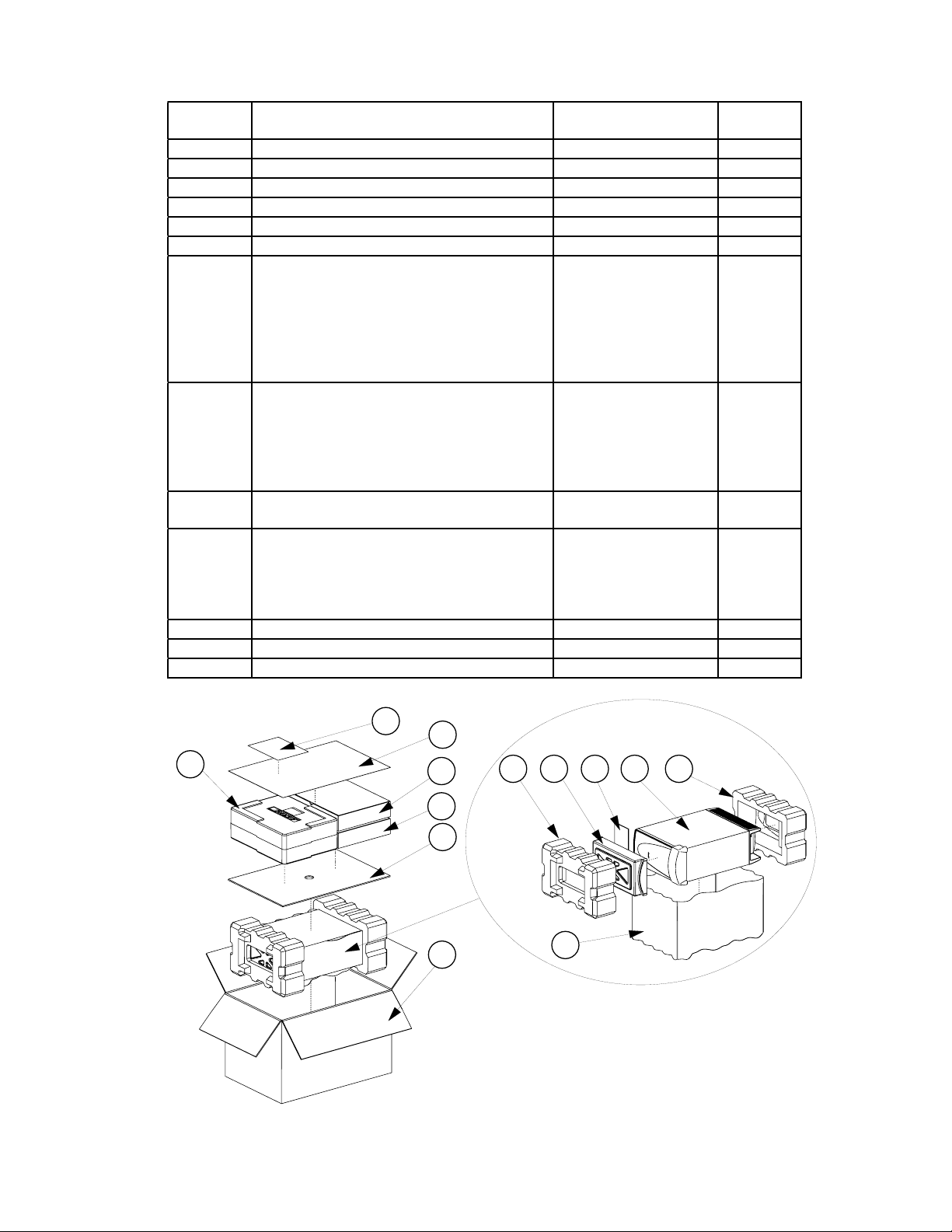
Lifestyle® 18 Home Theater System Packaging
Item
Number
1 CARTON 268787-001
2 PACKING, INSERT, GRILL 258465
3 PACKING, END CAP, EPS, FRONT 258466
4 PACKING, END CAP, EPS, REAR 258475
5 BAG, POLY 196638
6 PACKING PAD, 29.38X21.38 258469
7 AV28, US TUNER, RC1
AV28, EURO TUNER, RC4
AV28, JAP, IR REMOTE, RC2
8 PS18 BASS MODULE, DUAL V, BLACK
PS18 BASS MODULE, DUAL V, WHITE
9 SINGLE SAT, 5 PK, BLACK
SINGLE SAT, 5 PK, WHITE
10 ESSENTIALS KIT, LS18, 120V, (US)
ESSENTIALS KIT, LS18, 220V, (EURO)
ESSENTIALS KIT, LS18, 230V, (UK)
ESSENTIALS KIT, LS18, 240V, (AUS)
ESSENTIALS KIT, LS18, DUAL
11 FOAM, SHT, ADHESIVE BACK 263426
12 GUIDE, QUICK SETUP 268796
13 COMMITMENT LETTER 251001
Description Part Number Note
266440-1019
266440-2049
266440-3029
278799-619
278799-629
268791-119
268791-129
269660-1
269660-2
269660-4
269660-5
269660-6
1, 4
1
1
1
13
12
7
10
23 4
811
9
6
1
5
Figure 1. LS18 System Packaging Exploded View
5
Page 7
PS18/28/48 Service Manual
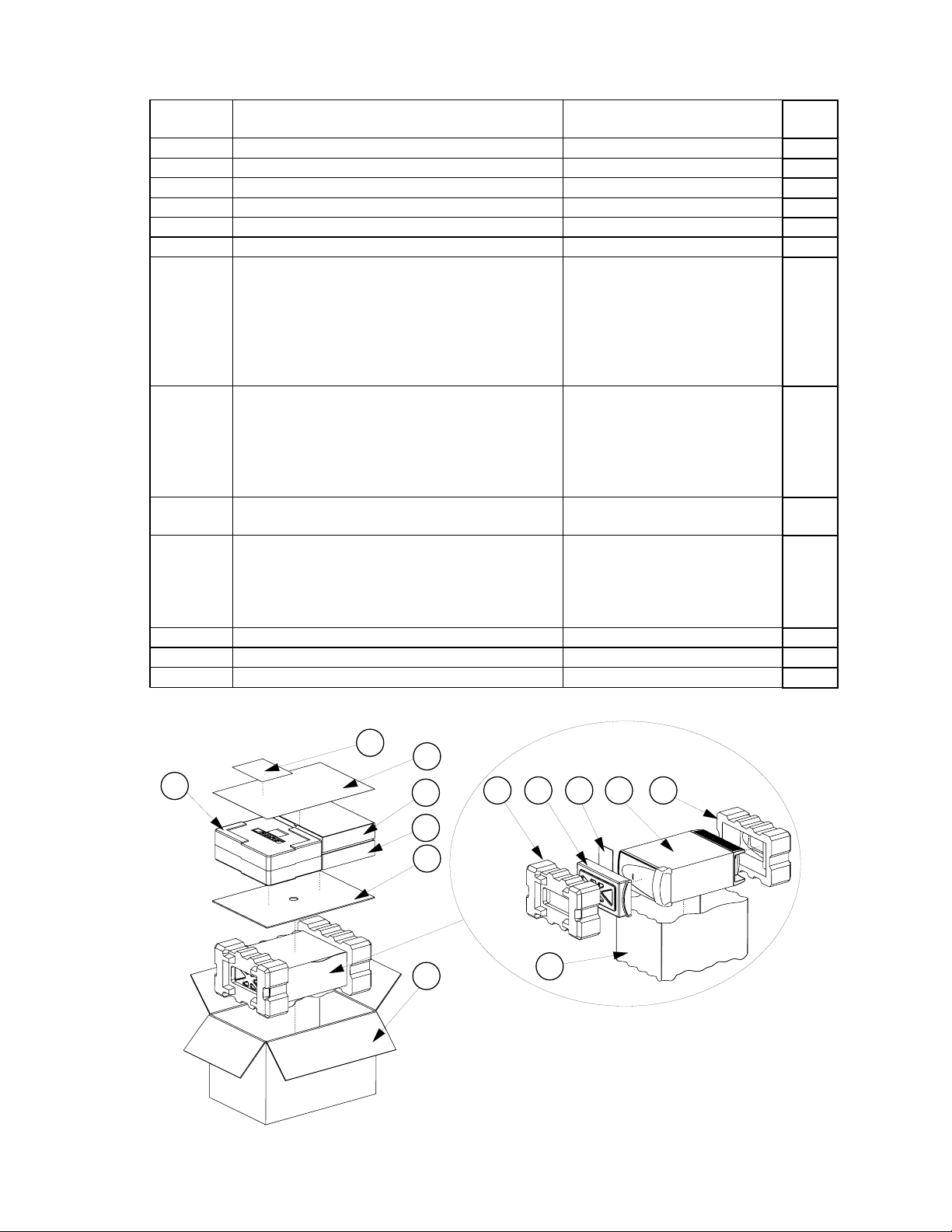
Lifestyle® 28 Home Theater System Packaging
Item
Number
1 CARTON, RSC 258474-002
2 PACKING INSERT GRILLE 258465
3 PACKING END CAP EPS FRONT 258466
4 PACKING END CAP EPS REAR 258475
5 BAG POLY 196638
6 PACKING PAD 29.38X21.38 258469
7 AV28, US TUNER, RC1
AV28, EURO TUNER, RC4
AV28, JAP, IR REMOTE, RC2
8 BASS MODULE, BLACK, DUAL V
BASS MODULE, WHITE, DUAL V
9 SAT ASSY, 5 PK, BLACK
SAT ASSY, 5 PK, WHITE
10 ESSENTIALS KIT, LS-35, 120V, (US)
ESSENTIALS KIT, LS-35, 220V, (EURO)
ESSENTIALS KIT, LS-35, 230V, (UK)
ESSENTIALS KIT, LS-35, 240V, (AUS)
ESSENTIALS KIT, LS-35, DUAL
11 FOAM, SHT, ADHESIVE BACK 263426
12 GUIDE, QUICK SETUP 266254
13 COMMITMENT LETTER 251001
Description Part Number Note
266440-1019
266440-2049
266440-3029
278799-619
278799-629
256815-113 OR -119
256815-123 OR -129
266217-1
266217-2
266217-4
266217-5
266217-6
1
1, 4
1
1
13
12
7
10
2
3 4
11
8
9
6
1
5
Figure 2. LS28 System Packaging Exploded View
6
Page 8

PS18/28/48 Service Manual
Lifestyle® 35 Home Theater System Packaging
Item
Number
1 CARTON, RSC 258474-002
2 PACKING INSERT GRILLE 258465
3 PACKING END CAP EPS FRONT 258466
4 PACKING END CAP EPS REAR 258475
5 BAG POLY 196638
6 PACKING PAD 29.38X21.38 258469
7
8 PS18/28/35, BASS MODULE, BLACK, DUAL V
9 SAT ASSY, 5 PK, BLACK
10 ESSENTIALS KIT, LS-35, 120V, (US)
11 FOAM, SHT, ADHESIVE BACK 263426
12 GUIDE, QUICK SETUP 266255
13 COMMITMENT LETTER 251001
AV28, US TUNER, RC1
AV28, EURO TUNER, RC4
AV28, JAP, IR REMOTE, RC2
PS18/28/35, BASS MODULE, WHITE, DUAL V
SAT ASSY, 5 PK, WHITE
ESSENTIALS KIT, LS-35, 220V, (EURO)
ESSENTIALS KIT, LS-35, 230V, (UK)
ESSENTIALS KIT, LS-35, 240V, (AUS)
ESSENTIALS KIT, LS-35, DUAL
Description Part Number Note
266440-1019
266440-2049
266440-3029
U278799-619
U278799-629
256816-013 OR -019
256816-023 OR -029
266218-1
266218-2
266218-4
266218-5
266218-6
1, 4
1
1
1
13
12
7
10
23 4
811
9
6
1
5
Figure 3. LS35 System Packaging Exploded View
7
Page 9

PS18/28/48 Service Manual
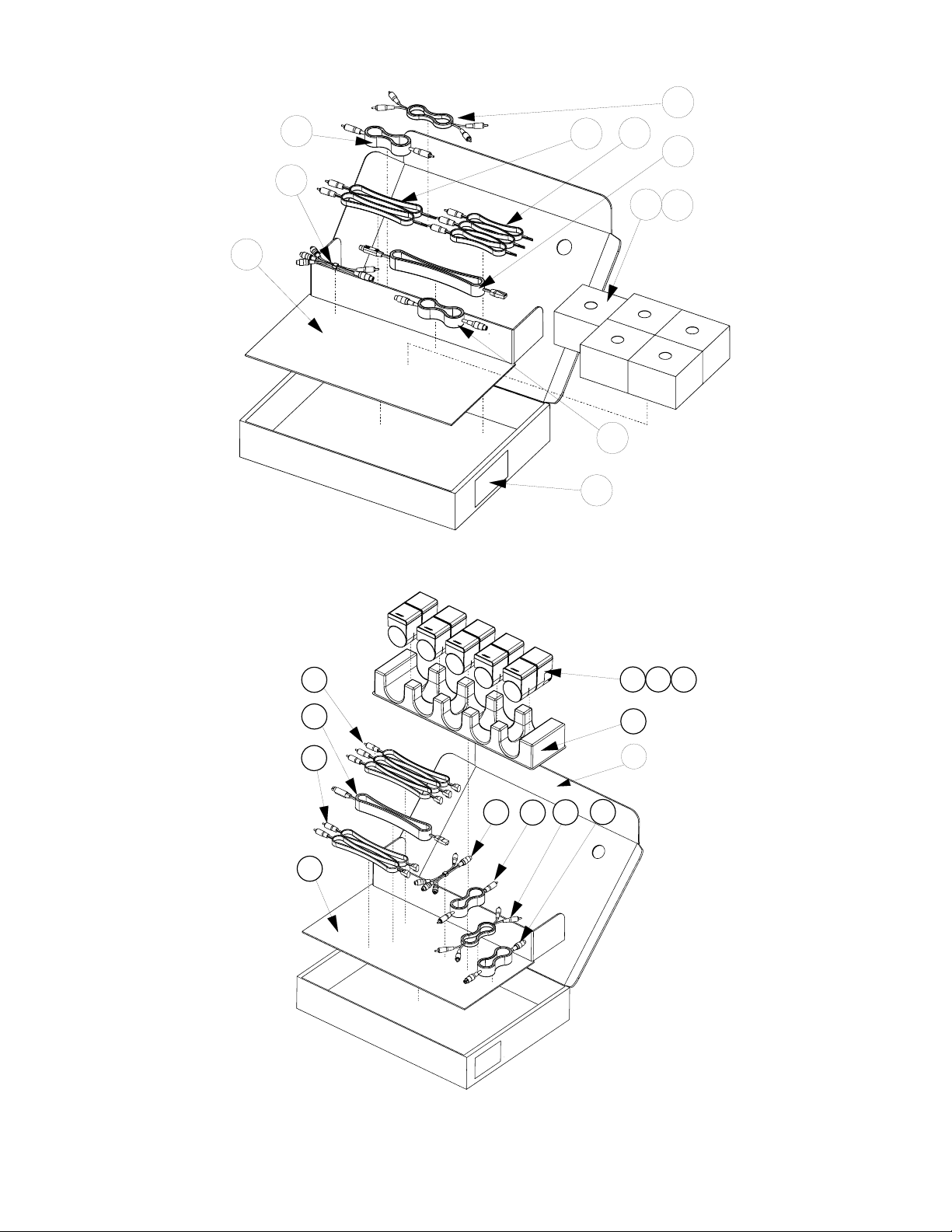
Lifestyle® 18/28/35 Essentials Kit Part List
Refer to figure 4
Item
Description Part Number Variant Packaging QTY Note
Number
1
REMOTE CONTROL 256119-001
REMOTE, CONTROL EU, 40MHZ 256119-002
2 BATTERY, AAA SIZE 179223-01
ANTENNA, FM DIPOLE, F-CONN 148589
3
ANTENNA, FM DIPOLE, PAL CONN 143185
POWER PACK, 35W, 120V, DCS-91 294295-001
4
POWER PACK, 35W, 230V, DCS-92 294295-007
POWER PACK, 35W, DUAL-V, DCS-94 294295-004
5 ANTENNA, ASSY, AM 199824-002
6 TV POWER SENSOR 258359
LINE CORD, 120V, AV28 279101-0310
LINE CORD, 220V, AV28 148203
7
LINE CORD, 230V, AV28 134725
LINE CORD, 240V, AV28 134726
LINE CORD, 120V, PS18/28/48 263453-006
LINE CORD, 220V, PS18/28/48 264355-006
8
LINE CORD, 230V, PS18/28/48 264356-006
LINE CORD, 240V, PS18/28/48 284241-006
9 BAG, POLY, 3X3MIL 194392
10 IR BLASTER 260335
11 TRAY PACK INSERT 258471
12 CARTON, ACCY KIT 258470-001
13 KIT, ADAPTIQTM 258363
14 SCART ADAPTOR 266221-001
LIT KIT, LS18 268793-1
LIT KIT, LS18 268793-2
LIT KIT, LS18 268793-4
LIT KIT, LS28 266219-1
15
LIT KIT, LS28 266219-2
LIT KIT, LS28 266219-4
LIT KIT, LS35 266220-1
LIT KIT, LS35 266220-2
LIT KIT, LS35 266220-4
US, CAN, AUS, EU, UK, SE ASIA/EAST ASI A,
SING
S. AF, MID E, DUAL-V
ALL
US, CAN, DUAL-V
AUS, EU, UK, SE ASIA/EAST ASIA, SING, S.
AF, MID E, DUAL-V
US, CAN
AUS, UK, SE ASIA/EAST ASIA, SING
EU, LATIN AMERICA, S. AF, MID E, DUAL-V
ALL
ALL
US, CAN, DUAL-V
EU, LATIN AMERICA, MID E, S. AF, SE
ASIA/EAST ASIA, DUAL-V
UK, SING
AUS
US, CAN, DUAL-V
EU, LATIN AMERICA, MID E, S. AF, SE
ASIA/EAST ASIA, DUAL-V
UK, SING
AUS
ALL
ALL
ALL
ALL
ALL
AUS, SING, EU, UK, SE ASIA/EAST ASIA, S.
AF, MID E, DUAL-V
US, CAN, LATIN AMERICA
EU, S. AF, MID E
AUS, UK, SING, SE ASIA/EAST ASIA
US, CAN, LATIN AMERICA
AUS, EU, S. AF, MID E
UK, SI NG, SE ASIA/EAST ASIA
US, CAN, LATIN AMERICA
AUS, EU, S. AF, MID E
UK, SI NG, SE ASIA/EAST ASIA
1
4
1
1 3
1
1
1 3
1 3
1
1
1
1
1
1
1
8
Page 10

8
PS18/28/48 Service Manual
15
7
6
3
5
13
1
10
2
9
12
4
14
Figure 4. LS18, 28, 35 Essentials Kit Exploded View
9
11
Page 11

Lifestyle® 18 Lit Kit Part List
Description Part Number Variant Packaging QTY Note
FOOT, CUBES 178321-04
FOOT, BASS MODULE 142839
OPERATING GUIDE, 3 LANG 269711
OPERATING GUIDE, 5 LANG 269713
INSTALL GUIDE, 3 LANG 269712
INSTALL GUIDE, 5 LANG 269714
BAG, POLY, 14.38x9.87x2 mil 103351
CARD, INFO, WARRANTY, MULTI LANG 181460
SHEET SLIP COMPONENT AUDIO 255805
ADDRESS PAGE 259434
CARD REGISTRATION AND
262933
WARRANTY
CARD, LIFESTYLE UPDATE 268157
DEC OF CONF 268794
Lifestyle® 28 Lit Kit Part List
PS18/28/48 Service Manual
ALL
ALL
ALL
EU, S. AF, MID E, DUAL-V
US, CAN, AUS, UK, EU, S. AF, MID E,
SING, SE ASIA/EAST ASIA, DUAL-V
EU, S. AF, MID E, DUAL-V
ALL
EU, S. AF, MID E, DUAL-V, AUS, UK,
SING, SE ASIA/EAST ASIA, DUAL-V
ALL
US, CAN, LATIN AMERICA
US, CAN, LATIN AMERICA
US, CAN, LATIN AMERICA
AUS, UK, SING, SE ASIA/EAST ASIA,
DUAL-V
4
4
1
1
1
1
1
1
1
1
Description Part
Number
FOOT, CUBES 178321-04
FOOT, BASS MODULE 142839
OPERATING GUIDE, 3 LANG 264341
OPERATING GUIDE, 5 LANG 264342
INSTALL GUIDE, 3 LANG 264343
INSTALL GUIDE, 5 LANG 264344
BAG, POLY, 14.38x9.87x2 mil 103351
CARD, INFO, WARRANTY, MULTI LANG 181460
SHEET SLIP COMPONENT AUDIO 255805
ADDRESS PAGE, BOSE 259434
CARD REGISTRATION AND WARRANTY 262933
CARD, LIFESTYLE UPDATE 268157
DEC OF CONF 266994
Lifestyle® 35 Lit Kit Part List
Description Part
Number
FOOT, CUBES 183621
FOOT BASS MODULE 142839
OPERATING, GUIDE, 3 LANG 264341
OPERATING GUIDE, 5 LANG 264342
INSTALL GUIDE, 3 LANG 264343
INSTALL, GUIDE, 5 LANG 264344
BAG, POLY, 14.38x9.87x2 mil 103351
CARD, INFO, WARRANTY, MULTI LANG 181460
SHEET SLIP COMPONENT AUDIO 255805
ADDRESS PAGE, BOSE 259434
CARD REGISTRATION AND WARRANTY 262933
CARD, LIFESTYLE UPDATE 268157
DEC OF CONF 266994
Variant Packaging QTY NOTE
ALL
ALL
ALL
AUS, EU, S. AF, MID E.
ALL
AUS, EU, S. AF, MID E.
ALL
AUS, EU, S. AF, MID E., UK, SING, SE
ASIA/EAST ASIA
ALL
US, CAN, LATIN AMERICA
US, CAN, LATIN AMERICA
US, CAN, LATIN AMERICA
AUS, EU, S. AF, MID E., UK, SING, SE
ASIA/EAST ASIA
Variant Packaging QTY NOTE
ALL
ALL
ALL
AUS, EU, S. AF, MID E.
ALL
AUS, EU, S. AF, MID E.
ALL
AUS, EU, S. AF, MID E., UK, SING, SE
ASIA/EAST ASIA
ALL
US, CAN, LATIN AMERICA
US, CAN, LATIN AMERICA
US, CAN, LATIN AMERICA
AUS, EU, S. AF, MID E., UK, SING, SE
ASIA/EAST ASIA
4
4
1
1
1
1
1
1
1
1
1
4
4
1
1
1
1
1
1
1
1
1
10
Page 12

PS18/28/48 Service Manual
Lifestyle® 18 Single Cube Speaker, 5 Pack Packaging List
Item
Number
1 SATELLITE ASSEMBLY, SINGLE, BLACK
SATELLITE ASSEMBLY, SINGLE, WHITE
2 CABLE, RJ-45/8 PIN DIN 260351-002 1
3 CABLE, AUDIO, DUAL RCA 185931-01 1
4 CABLE, VIDEO, 6', YL 183200 1
5 CABLE, S-VIDEO, 6’ 258369 1
6 CABLE, COMPONENT, VIDEO, ADAPTOR 260350 1
7 CABLES, SPKR, 18 AWG, L/C/R, BLACK
CABLES, SPKR, 18 AWG, L/C/R, WHITE
8 CABLE, SPEAKER, REAR, BLACK
CABLE, SPEAKER, REAR, BLACK
9 BAG, POLY, 10X12X2mil 144677 5
10 PACKING, INSERT 258473 1
11 CARTON, CHIPBOARD, SATELLITE 250555-001 5
12 CARTON, D/C 258472-001 1
Description Part Number Qty Note
250490-119
250490-129
180643-4
176201-4
180644
176202
5
1
1
Lifestyle®28 Double Cube Speaker, 5 Pack Packaging List
Item
Number
1 SATELLITE ASSEMBLY, SINGLE, BLACK
SATELLITE ASSEMBLY, SINGLE, WHITE
2 CABLE, RJ-45/8 PIN DIN 260351-002 1
3 CABLE, AUDIO, DUAL RCA 185931-01 1
4 CABLE, VIDEO, 6', YL 183200 1
5 CABLE, S-VIDEO, 6' 258369 1
6 CABLE, COMPONENT, VIDEO ADAPTOR 260350
7 CABLES, SPKR, 18 AWG, L/C/R, BLACK
CABLES, SPKR, 18 AWG, L/C/R, WHITE
8 CABLE, SPEAKER, REAR, BLACK
CABLE, SPEAKER, REAR, WHITE
9 BAG, POLY, 10X12X2 mil 144677 5
10 PACKING, INSERT 258473
11 CARTON, CHIPBOARD, SATELLITE, BLUE 197330-002 5
12 CARTON, D/C, SAT KIT 258472-001 1
Description Part Number Qty Note
192420-149
149420-159
180643-4
176204-4
180644
176202
5
1
1
Lifestyle® 35 Jewel Cube® Speaker, 5 Pack Packaging List
Item
Number
1 JEWEL CUBE SPEAKER, BLACK
JEWEL CUBE SPEAKER, WHITE
2 CABLE, RJ-45/8 PIN DIN 260351-002 1
3 CABLE, AUDIO, DUAL RCA 185931-01 1
4 CABLE, VIDEO, 6', YL 183200 1
5 CABLE, S-VIDEO, 6' 258369 1
6 CABLE, COMPONENT, VIDEO ADAPTOR 260350
7 CABLESET, 3PK, L/C/R, BLACK
CABLESET, 3PK, L/C/R, WHITE
8 CABLESET, 2PK, LS/RS, BLACK
CABLESET, 2PK, LS/RS, WHITE
9 BAG, POLY, 3X3.5X.004 185214 5
10 SATELLITE TRAY 190211-001 1
11 CARTON, D/C, SAT KIT 258472-001 1
12 PACKING, INSERT 258473 1
13 PACKING, PULL TAB, 2.25X1.75 188029-001 5
Description Part Number Qty Note
289523-019
289523-029
193145-04
193145-14
193146-03
193146-13
5
1
1
11
Page 13
PS18/28/48 Service Manual
3
10
4
8
6
5
12
Figure 5. LS18, 28 Cube Pack Exploded View
7
2
9
1
7
2
8
6
12
3
4
Figure 6. LS35 Cube Pack Exploded View
9
1
10
11
5
13
12
Page 14
Jewel Cube®Part List
PS18/28/48 Service Manual
Item
Number
1 TWIDDLERTM ASSY, 50MM 273244-002 or 291636-001 2
2 GRILLE, CUBE, BLACK, W/O SLOT
GRILLE, CUBE, WHITE, W/O SLOT
3 GRILLE, CUBE, BLACK, W/SLOT
GRILLE, CUBE, WHITE, W/SLOT
4 SNAP RING 313536-001 1
5 H-RING, SEAL, BLACK
H-RING,SEAL NATURAL
6 HARNESS ASSY, TWIDDLER 196136-01 1
7 SCREW, HILO, 4-16x.375, PAN, XREC 181621-06 8
8 DAMPER, ANTI-BUZZ 185951 8
9 NAMEPLATE, BOSE, BLACK/PEWTER
NAMEPLATE, BOSE, WHITE/PEWTER
Description Part Number Qty Note
192935-01
192935-03
192935-02
192935-04
178710-01
178710-02
178725-01
178725-02
1
1
2
1
4
1
x2
5
2
8
x8
6
3
9
x8
7
Figure 7. Jewel Cube Exploded View
13
Page 15
PS18/28/48 Service Manual
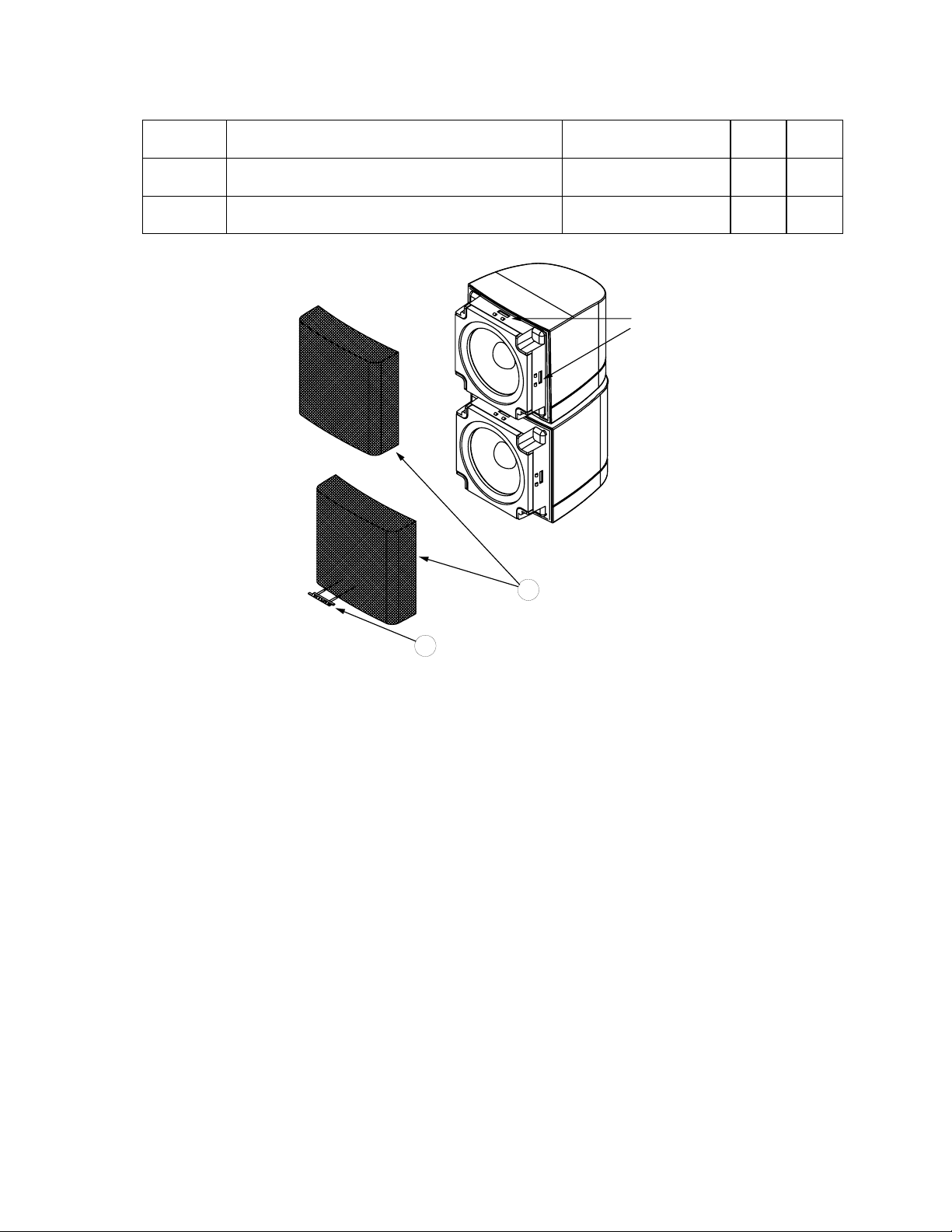
Single and Dual Cube Speaker Part List
Item
Number
1 GRILLE, BLACK
GRILLE, WHITE
2 LOGO, 1" DIAMOND CUT, BLACK
LOGO, 1" DIAMOND CUT, WHITE
Description Part Number Qty Note
192410-019
192410-029
193250-11
193250-12
Release the grille
from these catches
2
1
1
2
Figure 8. Cube Exploded View
14
Page 16

PS18/28/48 Service Manual
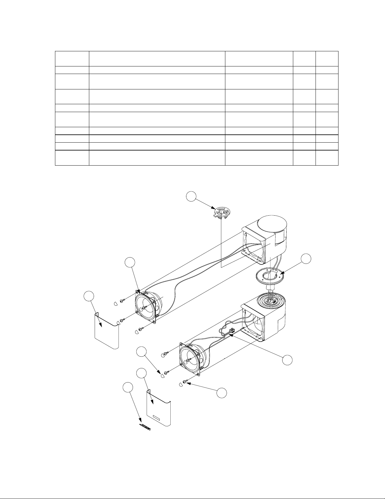
PS18/28/48 Bass Module Assembly Part List
Item
Number
1 AMP MODULE ASSY, 120V 277096-132F or
AMP MODULE ASSY, 230V
AMP MODULE ASSY, 100V
AMP MODULE ASSY, DUAL-V
2 SCREW, TAPP, 8-11x.75, PAN, XRC/SQ 172672-12 14
3 GRILLE, BLACK
GRILLE, WHITE
4 COVER, REAR, BLACK
COVER, REAR, WHITE
5 SCREW, 8-32X.75, RLX, PN, QDRX, BLACK
SCREW, 8-32X.75, RLX, PN, QDRX, WHITE
6 SCREW TAPP, 8-11X1.25, PAN, XRS/C 172672-20 2
7 LOGO, NAMEPLATE, GRILL, BLACK
LOGO, NAMEPLATE, GRILL, WHITE
8 INSERT, PLASTIC, REAR COVER, BLACK
INSERT, PLASTIC, REAR COVER, WHITE
9 GASKET, GILLE EDGE 260349 2
10 TAPE, VHB, REAR, COVER, PLUG 262871 1
- WOOFER ASSY,5.25" 2.33 OHM 279424-003 2
- GASKET, WOOFER 263455 2
Description Part Number Qty Note
277096-631F
277096-631F
277096-631F
277096-631F
256761-001
256761-002
256762-001
256762-002
260400-12
193637-20
258484-01
258484-02
258485-01
258785-02
1, 4
1
1 3
2
1
1
Important - Note 4. This part is set to the Lifestyle® 28/38 system equalization. To use this part on
a Lifestyle® 18, 35 or 48 system, refer to the instructions located on page 31 for setting the Equalizer using TAP commands. Except for the Lifestyle® 18 system, in place of using TAP commands to
set the EQ, the customer may use the Bose® AdaptIQTM audio calibration system to customize the
EQ to their room. The Lifestyle® 18 system bass module is set to provide a lower outut to match
the single cubes, which can only be set using TAP commands. The AdaptIQ audio calibration
system is shipped with the Lifestyle® 18,28,35,38,48 system.
For other notes referenced, refer to the part list notes at the beginning of the part list section.
9
11
1
2
4
5
3
7
8
10
6
Figure 9. Bass Module Exploded View
15
Page 17

PS18/28/48 Service Manual
PS18/28/48 Amplifier Module Assembly Part List
Item
Number
11 POWER PCB ASSY, 120V/100V
POWER PCB ASSY, 230V
POWER PCB ASSY, DUAL-V
12 AMP PCB ASSY 285826-001 or 299699-001 (ROHS) 1, 2
13 DSP PCB ASSY 285828-101 or 288894-102 (ROHS) 1, 2, 4
14 ENCLOSURE, HEATSINK 282578-001 1 3
15 HOUSING, LOWER, AMPLIFIER 256142-001 1 3
16 HEATSINK, ASSY, DSP 260369 1
17 PAD, CONDUCTIVE, THERMAL 258353-001 1
18 PAD, CONDUCTIVE, THERMAL 258356-001 1
19 SCREW, 6-32X1/2 THREAD ROLLING 258492-08 18
20 GASKETING, EMI 256826-001 1
21 GASKETING, EMI 256826-002 1
22 GASKET, CONNECTOR 256827 1
23 BAR, SPRING, POWER AMPS 260375 1
24 FOAM, SHIM, DIODES 258483 1
25 CLIP, GROUNDING, FINGER STOCK 262870-001 4
26 PAD, HEXAGON, .433 X .063 262869 3
27 SHIM, ELECTRONICS MODULE 263456 1
28 GASKET FOAM EMI 262635-025 1
- FOAM, SHIM, POWER AMP 263454 1
Description Part Number Qty Note
285837-003
299698-002
285837-006
(ROHS)
1 1, 2, 3
20
21
2 of 2
22
11
28
19
19
27
15
24
11
26
23
12
13
18
16
14
1 of 2
25
17
Figure 10. Amplifier Module Exploded View
16
Page 18
PS18/28/48 Service Manual
Power PCB Assembly 260327-XXXX, PCB 266459-001
PS18/28/48 Electrical Part List
Resistors
Reference
Designator
R101 10 OHM, 1206, 1/8W, 5% 124895-1005
R102 33 OHM, 1206, 1/8W, 5% 124895-3305
R103 10 OHM, 1206, 1/8W, 5% 124895-1005
R104 100 OHM, 1206, 1/8W, 5% 124895-1015
R106 1.00K, 1206, 1/8W, 5% 124895-1025
R107 2.0K, 0603, .1W, 5% 199403-202
R109 20K, 0603, .1W, 5% 199403-203
R110 1M, 0603, .1W, 5% 199403-105
R111 43.2K, 0603, .1W, 1% 191465-4322
R112 60.4K, 0603, .1W, 1% 191465-6042
R113 47.5K, 0603, .1W, 1% 191465-4752
R121 75.0K, 1206, 1/8W, 1% 124894-7502
R122 75.0K, 1206, 1/8W, 1% 124894-7502
R123 75.0K, 1206, 1/8W, 1% 124894-7502
R124 75.0K, 1206, 1/8W, 1% 124894-7502
R127 9.1M, 0603, .1W, 5% 199403-915
R128 220K, 0603, .1W, 5% 199403-224
R129 261K, 1206, 1/4W, 1% 124894-2613
R150 681 OHM, 1206, 1/8W, 1% 124894-6810
R151 2.87K, 0603, 100MW, 1% 191465-2871
R152 20K, 0603, .1W, 5% 199403-203
R153 75.0K, 1206, 1/8W, 1% 124894-7502
R154 75.0K, 1206, 1/8W, 1% 124894-7502
R155 75.0K, 1206, 1/8W, 1% 124894-7502
R156 75.0K, 1206, 1/8W, 1% 124894-7502
R157 261K, 1206, 1/4W, 1% 124894-2613
R158 220 OHM, 1206, 1/4W, 5% 124895-2215 DUAL-V
R159 220 OHM, 1206, 1/4W, 5% 124895-2215 DUAL-V
R160 220 OHM, 1206, 1/4W, 5% 124895-2215 DUAL-V
R161 220 OHM, 1206, 1/4W, 5% 124895-2215 DUAL-V
R201 10 OHM, FUSING, AX, RAD TAPE 260352-100 3
Description Part Number Note
R202 10 OHM, FUSING, AX, RAD TAPE 260352-100 3
R207 100K, 0603, .1W, 1% 191465-1003
R208 10K, 0603, .1W, 1% 191465-1002
R212 10K, 0603, .1W, 1% 191465-1002
R213 10K, 0603, .1W, 1% 191465-1002
R216 68.1K, 0603, .1W, 1% 191465-6812
R217 13.7K, 0603, 0.1W, 1% 191465-1372
R218 5.11K, 0603, .1W, 1% 191465-5111
R219 2.1K, 0603, .1W, 1% 191465-2101
R220 432 OHM, 0603, .1W, 1% 191465-4320
R223 432 OHM, 1206, 1/4W, 1% 124894-4320
R224 2.0K, 0603, .1W, 5% 199403-202
R225 49.9K, 0603, .1W, 1% 191465-4992
R226 432 OHM, 0603, .1W, 1% 191465-4320
R227 3.01K, 0603, .1W, 1% 191465-3011
R228 432 OHM, 0603, .1W, 1% 191465-4320
R229 3.01K, 0603, .1W, 1% 191465-3011
R230 100K, 0603, .1W, 1% 191465-1003
R231 100K, 0603, .1W, 1% 191465-1003
17
Page 19

PS18/28/48 Service Manual
Power PCB Assembly 260327-XXXX, PCB 266459-001
PS18/28/48 Electrical Part List
Resistors (continued)
Reference
Designator
R234 5.9K, 0603, .1W, 1% 191465-5901
R235 10K, 0603, .1W, 1% 191465-1002
R236 2.2 OHM, FUSING, 1/2W, 5% 188460-2R2 3
R237 2.2 OHM, FUSING, 1/2W, 5% 188460-2R2 3
R238 100K, 0603, .1W, 1% 191465-1003
R300 2.00K, 1206, 1/8W, 5% 124895-2025
R301 2.49K, 1206, 1/8W, 1% 124894-2491
R303 20K, 0603, .1W, 5% 199403-203
R304 20K, 0603, .1W, 5% 199403-203
R305 18.7K, 0603, .1W, 1% 191465-1872
R306 2.87K, 0603, 100MW, 1% 191465-2871
R403 261K, 1206, 1/4W, 1% 124894-2613
R404 18.7K, 0603, .1W, 1% 191465-1872
R405 91K, 0603, .1W, 5% 199403-913
R406 390 OHM, 0603, .1W, 5% 199403-391
R407 261K, 1206, 1/4W, 1% 124894-2613
R410 261K, 1206, 1/4W, 1% 124894-2613
R411 261K, 1206, 1/4W, 1% 124894-2613
Description Part Number Note
Capacitors
Reference
Designator
C101 0.1uF, FILM, X1, 310VAC, 15MM 260387-104B 3
C101 0.1uF, FILM, X2, 275VAC, 15MM 268166-104B 3
C102 0.1uF, FILM, X1, 310VAC, 15MM 260387-104B
C102 0.1uF, FILM, X2, 275VAC, 15MM 268166-104B 100V,
C103 1.5nF, FILM, Y2, 250VAC 254145-152A 3
C104 1.5nF, FILM, Y2, 250VAC 254145-152A 3
C106 .47uF, BOX, 85, 50V, 5% 137127-474
C110 470uF, EL, 105, 250V, 20% 170170 3
C111 470uF, EL, 105, 250V, 20% 170170 3
C112 .047uF, FILM, 630VDC, 85, 10% 260357-473T21
C113 470pF, MICA, 10%, 500V 254164-471B
C114 470pF, MICA, 10%, 500V 254164-471B
C115 18000pF, FILM, 2KVDC, 5% 258419-183C
C117 1.0uF, EL, 105, 50V, 20% 196991-1R0H
C118 10uF, EL, 105, 25V, 20% 196991-100E
C119 .47uF, BOX, 85, 50V, 5% 137127-474
C120 .01uF, 0603, X7R, 50V 191470-103
C121 .01uF, 0603, X7R, 50V 191470-103
Description Part Number Note
100V,
230V,
DUAL-V
230V,
DUAL-V
18
Page 20

PS18/28/48 Service Manual
Power PCB Assembly 260327-XXXX, PCB 266459-001
PS18/28/48 Electrical Part List
Capacitors (continued)
Reference
Designator
C122 220pF 0603, COG, 50V, 5% 188454-221
C126 .047uF, 0603, X7R, 5%, 25V 196999-473
C128 .047uF, 0603, X7R, 5%, 25V 196999-473
C129 .47uF, BOX, 85, 50V, 5% 137127-474
C130 .047uF, 0603, X7R, 5%, 25V 196999-473
C201 5.6uF, FILM, 10%, 100VDC 260333-565C
C202 5.6uF, FILM, 10%, 100VDC 260333-565C
C211 1.0uF, FILM, 10%, 100 VDC 260333-105A
C212 1.0uF, FILM, 10%, 100 VDC 260333-105A
C213 10uF, EL, 105, 25V, 20% 190382-100E
C214 10uF, EL, 105, 25V, 20% 190382-100E
C215 .022uF, 0603, X7R, 25V 196999-223
C219 .047uF, 0603, X7R, 5%, 25V 196999-473
C220 .047uF, 0603, X7R, 5%, 25V 196999-473
C233 .001uF, BOX, 85, 100V, 5% 137127-102
C234 .001uF, BOX, 85, 100V, 5% 137127-102
C235 .001uF, BOX, 85, 100V, 5% 137127-102
C236 .001uF, BOX, 85, 100V, 5% 137127-102
C237 3300pF, 1206, X7R, 50V, 10% 124957-332
C238 3300pF, 1206, X7R, 50V, 10% 124957-332
C239 3300pF, 1206, X7R, 50V, 10% 124957-332
C240 22uF, EL, 105, 63V, 20% 196991-220I
C241 22uF, EL, 105, 63V, 20% 196991-220I
C255 .1uF, 0805, X7R, 10%, 25V 181264-104
C256 .1uF, 0805, X7R, 10%, 25V 181264-104
C300 .47uF, BOX, 85, 50V, 5% 137127-474
C301 .047uF, 0603, X7R, 5%, 25V 196999-473
C401 100pF, 0603, COG, 50V, 5% 188454-101
C402 47uF, EL, 105, 16V, 20% 126767-470 DUAL-V
C408 .047uF, FILM, 630VDC, 85, 10% 260357-473T21 DUAL-V
Description Part Number Note
Diodes
Reference
Designator
BR1 BRIDGE, 600V, 4A 256789-600 3
D101 MMBD914LT1, SOT 148582
D102 MMBD914LT1, SOT 148582
D103 MMBD914LT1, SOT 148582
D105 MMBD914LT1, SOT 148582
D106 MMBD914LT1, SOT 148582
D108 SHOTTKY, BAT42W, SOD-123 196984-002
D111 MMBD914LT1, SOT 148582
D112 SHOTTKY, BAT42W, SOD-123 196984-002
D150 BAV70, SOT-23 147249
D201 PWR SCHOTTKY, 8AX2, 80V 258431-80
D202 MMBD914LT1, SOT 148582
D203 PWR SCHOTTKY, 8A, 80V 258437-080
D204 PWR SCHOTTKY, 8A, 80V 258437-080
D205 MMBD914LT1, SOT 148582
D206 MMBD914LT1, SOT 148582
Description Part Number Note
19
Page 21

PS18/28/48 Service Manual
Power PCB Assembly 260327-XXXX, PCB 266459-001
PS18/28/48 Electrical Part List
Resistors (continued)
Reference
Designator
D207 BAV70, SOT-23 147249
D208 SOT23, BAV99 147239
D209 1N4001, RECTIFIER, 400V, 1A 260340-1
D210 1N4001, RECTIFIER, 400V, 1A 260340-1
D211 BAV99, SOT23 147239
D401 RECTIFIER, 700V, 1A, 12. 5MM 260340-7 DUAL-V
ZR101 1N5246, ZEN, 12V, 225MW, 5% 135247-5242
ZR102 1N5246, ZEN, 12V, 225MW, 5% 135247-5242
ZR103 ZENER, 3.3V 135247-5226
ZR300 SOT-23, ZEN, 6.2V, 225MW, 5% 135247-5234
Description Part Number Note
Transistors
Reference
Designator
Q101 CLIP, TINNERMAN 258354
Q101 MOS FET, N-CH, 500V, 6.6A 254121-001
Q102 CLIP, FET 258354
Q102 MOSFET, N-CH, 500V, 6.6A 254121-001
Q103 MFET, N, SOT 252043
Q104 MMBT3906, PNP, SOT 148596
Q201 MMBT3904, TRANSISTOR, NPN, SOT 146819
Q300 MMBT3906, PNP, SOT 148596
Q301 MMBT3904, TRANSISTOR, NPN, SOT 146819
Q401 TRIAC, AVS12CB 254188-001 DUAL-V
Description Part Number Note
Integrated Circuits
Reference
Designator
U101 HV RESONANT CONTROL, L6598 254119-001
U102 OPTO ISOLATOR, CNY17F-1 254120-001 3
U103 OPTO ISOLATOR, CNY17F-1 254120-001 3
U201 VOLT REG, 37V, POS, 137927
U202 VOLT REG, 37V, NEG 137927
U203 TLO74D, QUADOPAMP, SOIC 186112
U401 AUTO V, SW, 110/220V, 50/60HZ 254187-001 DUAL-V
Description Part Number Note
20
Page 22

PS18/28/48 Service Manual
Power PCB Assembly 260327-XXXX, PCB 266459-001
PS18/28/48 Electrical Part List
Miscellaneous
Reference
Designator
L101 2.2uH, COMMON MODE 187598-2R2 3
L102 2.2uH, COMMON MODE 187598-2R2 3
L103 1.5MH, 2.0A, TOROIDAL 269334-001 100V,
L201 12.5uH 176500
L202 12.5uH 176500
L103 1.5MH, 2.0A,TOROIDAL 269334-001 DUAL-V
T101 CHOKE, LINE, COMMON MODE, 3MH 260371-001 3
T102 XFORMER, PWR, HIGH-FREQ, EE42/20 258422-001
F101 FUSE, 4.0A, SLO BLO 177311-04000 3
F101 FUSE CLIP, 5MM 178548 3
J101 CONN, AC INPUT, IEC320, W/O WINGS 256777-001 3
J102 CABLE, AC INPUT 258454-001 3
J103 CONNECTOR, 2 POS, POWER 258436 3
J104 CLIP, GROUND, SPRING 260365-001
J105 CLIP, GROUND, SPRING 260365-001
J204 CONNECTOR, CARDEDGE, 20-POS 258423-020
J205 CONN, BRD TO BRD, 24 POS 258426-24
RT100 PTC, TEMP SENSE, 16V, 125C, 20% 258497-125
VR101 VARISTOR, MET OX, 275V, 75 JOULE 170189 100V,
VR102 VARISTOR, METOX, 150V, 45 JOULE 170186 3
VR103 VARISTOR, METOX, 150V, 45 JOULE 170186 3
Description Part Number Note
230V
230V,
DUAL-V
120V
JP1 JUMPER, 22AWG, INSUL, 5MM, TAPED 179645 120V
S1 SWITCH, POWER, 16A, PC MOUNT 196101-001
21
Page 23

PS18/28/48 Service Manual
Amplifier PCB Assembly 266999-0, PCB 267083-001
PS18/28/48 Electrical Part List
Resistors
Reference
Designator
R1 5.1K, 0603, .1W, 5% 199403-512
R2 100K, 0603, .1W, 5% 199403-104
R3 2.0K, 0603, .1W, 1% 191465-2001
R4 1.0K, 0603, .1W, 1% 191465-1001
R5 10K, 0603, .1W, 5% 199403-103
R6 10K, 0603, .1W, 5% 199403-103
R7 2.32K, 0603, .1W, 1% 191465-2321
R9 JUMPER, CHIP 0805 133627
R101 560 OHMS, 0603, .1W, 5% 199403-561
R102 10K, 0603, .1W, 1% 191465-1002
R103 3.9K, 0603, .1W, 1% 191465-3901
R104 4.7 OHM, 0805, 1/10W,5% 133626-4R75
R105 100K, 0603, .1W, 5% 199403-104
R106 15K, 0603, .1W, 5% 199403-153
R201 560 OHMS, 0603, .1W, 5% 199403-561
R203 3.9K, 0603, .1W, 1% 191465-3901
R204 4.7 OHM, 0805, 1/10W, 5% 133626-4R75
R301 560 OHMS, 0603, .1W, 5% 199403-561
R302 10K, 0603, .1W, 1% 191465-1002
R303 3.9K, 0603, .1W, 1% 191465-3901
R304 4.7 OHM, 0805, 1/10W, 5% 133626-4R75
R305 100K, 0603, .1W, 5% 199403-104
R401 560 OHMS, 0603, .1W, 5% 199403-561
R402 10K, 0603, .1W, 1% 191465-1002
R403 3.9K, 0603, .1W, 1% 191465-3901
R404 4.7 OHM, 0805, 1/10W, 5% 133626-4R75
R405 100K, 0603, .1W, 5% 199403-104
R406 5.1K, 0603, .1W, 5% 199403-512
R407 15K, 0603, .1W, 5% 199403-153
R501 560 OHMS, 0603, .1W, 5% 199403-561
R502 10K, 0603, .1W, 1% 191465-1002
R503 3.9K, 0603, .1W, 1% 191465-3901
R504 4.7 OHM, 0805, 1/10W, 5% 133626-4R75
R505 100K, 0603, .1W, 5% 199403-104
R506 10K, 0603, .1W, 1% 191465-1002
R601 3.9K, 0603, .1W, 1% 191465-3901
R602 10K, 0603, .1W, 1% 191465-1002
R603 4.7 OHM, 0805, 1/10W, 5% 133626-4R75
R604 10.0 OHM, 0805, 1/10W, 1% 133625-10R0
R605 100K, 0603, .1W, 5% 199403-104
R606 10.0 OHM, 0805, 1/10W, 1% 133625-10R0
R607 5.1K, 0603, .1W, 5% 199403-512
R608 100 OHM, 1206, 1/8W, 5% 124895-1015
R609 100K, 0603, .1W, 5% 199403-104
R610 200 OHMS, 0603, .1W, 5% 199403-201
R612 300 OHMS, 0603, .1W, 5% 199403-301
Description Part Number Note
22
Page 24

PS18/28/48 Service Manual
Amplifier PCB Assembly 266999-0, PCB 267083-001
PS18/28/48 Electrical Part List
Capacitors
Reference
Designator
C1 10uF, EL, 85, 25V, 20% 177902-100E
C4 0.1uF, 0805, X7R, 50V, 10% 133624
C10 0.1uF, 0805, X7R, 50V, 10% 133624
C12 0.1uF, 0805, X7R, 50V, 10% 133624
C13 0.1uF, 0805, X7R, 50V, 10% 133624
C14 0.1uF, 0805, X7R, 50V, 10% 133624
C15 0.1uF, 0805, X7R, 50V, 10% 133624
C16 0.1uF, 0805, X7R, 50V, 10% 133624
C17 0.1uF, 0805, X7R, 50V, 10% 133624
C18 0.1uF, 0805, X7R, 50V, 10% 133624
C19 0.1uF, 0805, X7R, 50V, 10% 133624
C20 0.1uF, 0805, X7R, 50V, 10% 133624
C21 0.1uF, 0805, X7R, 50V, 10% 133624
C101 1uF, EL, 85, 50V , 20% 177902-010H
C102 .0068uF, 0603, X7R, 50V 191470-682
C104 0.1uF, 0805, X7R, 50V, 10% 133624
C106 .01uF, 0603, X7R, 50V 191470-103
C109 470pF, 0603, COG, 50V, 5% 188454-471
C110 68pF, 0805, COG, 50V, 5% 133622-680
C111 68pF, 0805, COG, 50V, 5% 133622-680
C201 1uF, EL, 85, 50V , 20% 177902-010H
C202 .0068uF, 0603, X7R, 50V 191470-682
C205 .01uF, 0603, X7R, 50V 191470-103
C209 470pF, 0603, COG, 50V, 5% 188454-471
C301 1uF, EL, 85, 50V , 20% 177902-010H
C302 .0068uF, 0603, X7R, 50V 191470-682
C304 0.1uF, 0805, X7R, 50V, 10% 133624
C305 .01uF, 0603, X7R, 50V 191470-103
C309 470pF, 0603, COG, 50V, 5% 188454-471
C310 68pF, 0805, COG, 50V, 5% 133622-680
C401 1uF, EL, 85, 50V , 20% 177902-010H
C402 .0068uF, 0603, X7R, 50V 191470-682
C404 0.1uF, 0805, X7R, 50V, 10% 133624
C406 .01uF, 0603, X7R, 50V 191470-103
C409 470pF, 0603, COG, 50V, 5% 188454-471
C410 68pF, 0805, COG, 50V, 5% 133622-680
C501 1uF, EL, 85, 50V , 20% 177902-010H
C502 .0068uF, 0603, X7R, 50V 191470-682
C504 0.1uF, 0805, X7R, 50V, 10% 133624
C505 .01uF, 0603, X7R, 50V 191470-103
C506 0.1uF, 0805, X7R, 50V, 10% 133624
C507 0.1uF, 0805, X7R, 50V, 10% 133624
C508 0.1uF, 0805, X7R, 50V, 10% 133624
C509 470pF, 0603, COG, 50V, 5% 188454-471
C510 68pF, 0805, COG, 50V, 5% 133622-680
C601 10uF, EL, 85, 25V, 20% 177902-100E
C602 22uF, EL, 85, 20%, 16V 177902-220C
C603 0.1uF, 0805, X7R, 50V, 10% 133624
C604 .047uF, 0603, X7R, 5%, 25V 196999-473
C606 .047uF, 0603, X7R, 5%, 25V 196999-473
C607 .047uF, 0805, X7R, 50V, 10% 133623-473
C608 100pF, 0805, COG, 50V, 5% 133622-101
Description Part Number Note
23
Page 25

PS18/28/48 Service Manual
Amplifier PCB Assembly 266999-0, PCB 267083-001
PS18/28/48 Electrical Part List
Diodes
Reference
Designator
D101 BAV70, SOT-23 147249
D301 BAV70, SOT-23 147249
D401 BAV70, SOT-23 147249
D402 BAV70, SOT-23 147249
ZR1 DIODE, ZENER, 3.3V 135247-5226
ZR2 1N5236, DIODE, ZEN, 7.5V, 225 mW 135247-5236
Description Part Number Note
Transistors
Reference
Designator
Q1 2SC2812 SOT23 134741
Q2 NPN, SOT, 47K 146817
Q3 NPN, SOT, 47K 146817
Q4 2SA1179N6-CPA-TB 258007
Q5 2SA1179N6-CPA-TB 258007
Q6 2SA1179N6-CPA-TB 258007
Q7 NPN, SOT, 47K 146817
Q401 2SC2812 SOT23 134741
Q601 NPN, 25A, 80V 256095-001 OR
Q602 PNP, 25A, 80V 256096-001 OR
Q603 2SC2812 SOT23 134741
Q604 NPN, SOT, 47K 146817
Description Part Number Note
256095-002
256096-002
Integrated Circuits
Reference
Designator
U1 LM4766T, 2X25W 267330-001
U2 LM4766T, 2X25W 267330-001
U3 LM4766T, 2X25W 267330-001
Description Part Number Note
Miscellaneous
Reference
Designator
J2 CONNECTOR, BRD-TO-BRD, 24-POS 258455-24
J3 CONN, PHONO JACK, 5 POS, CUSTOM 260382-001
J4 CONN, HEADER, RTANG, JSTS2P-VH 190552-02
Description Part Number Note
24
Page 26

Amplifier PCB 267332-0, PCB 267331-001
PS18/28/48 Electrical Part List
Resistors
Reference
Designator
R1 5.1K, 0603, .1W, 5% 199403-512
R2 100K, 0603, .1W, 5% 199403-104
R4 1K, 0603, .1W, 1% 191465-1001
R5 47K, 0603, .1W, 5% 199403-473
R6 47K, 0603, .1W, 5% 199403-473
R7 2.32K, 0603, .1W, 1% 191465-2321
R9 JUMPER, CHIP, 0805 133627
R101 560 OHM, 0603, .1W, 5% 199403-561
R102 9.09K OHM, 0603, .1W, 1% 191465-9091
R103 3.9K, 0603, .1W, 1% 191465-3901
R104 2 OHM, 0805, 1/10W, 5% 133626-2R05
R105 100K, 0603, .1W, 5% 199403-104
R106 15K, 0603, .1W, 5% 199403-153
R113 20K, 0603, .1W, 5% 199403-203
R150 4.70 OHM, 0603, 100 MW, 1%, SMD 191465-4R70
R201 560 OHM, 0603, .1W, 5% 199403-561
R203 3.9K, 0603, .1W, 1% 191465-3901
R204 2 OHM, 0805, 1/10W, 5% 133626-2R05
R213 20K, 0603, .1W, 5% 199403-203
R250 4.70 OHM, 0603, 100 MW, 1%, SMD 191465-4R70
R301 560 OHM, 0603, .1W, 5% 199403-561
R302 9.09K OHM, 0603, .1W, 1% 191465-9091
R303 3.9K, 0603, .1W, 1% 191465-3901
R304 2 OHM, 0805, 1/10W, 5% 133626-2R05
R305 100K, 0603, .1W, 5% 199403-104
R313 20K, 0603, .1W, 5% 199403-203
R350 4.70 OHM, 0603, 100 MW, 1%, SMD 191465-4R70
R401 560 OHM, 0603, .1W, 5% 199403-561
R402 9.09K OHM, 0603, .1W, 1% 191465-9091
R403 3.9K, 0603, .1W, 1% 191465-3901
R404 2 OHM, 0805, 1/10W, 5% 133626-2R05
R405 100K, 0603, .1W, 5% 199403-104
R406 5.1K, 0603, .1W, 5% 199403-512
R407 15K, 0603, .1W, 5% 199403-153
R413 20K, 0603, .1W, 5% 199403-203
R450 4.70 OHM, 0603, 100 MW, 1%, SMD 191465-4R70
R501 560 OHM, 0603, .1W, 5% 199403-561
R502 9.09K OHM, 0603, .1W, 1% 191465-9091
R503 3.9K, 0603, .1W, 1% 191465-3901
R504 2 OHM, 0805, 1/10W, 5% 133626-2R05
R505 100K, 0603, .1W, 5% 199403-104
R506 9.09K OHM, 0603, .1W, 1% 191465-9091
R513 20K, 0603, .1W, 5% 199403-203
R550 4.70 OHM, 0603, 100 MW, 1%, SMD 191465-4R70
R601 3.9K, 0603, .1W, 1% 191465-3901
R602 9.09K OHM, 0603, .1W, 1% 191465-9091
R603 2 OHM, 0805, 1/10W, 5% 133626-2R05
R604 10.0 OHM, 0805, 1/10W, 1% 133625-10R0
R605 100K, 0603, .1W, 5% 199403-104
R606 10.0 OHM, 0805, 1/10W, 1% 133625-10R0
R607 5.1K, 0603, .1W, 5% 199403-512
R609 100K, 0603, .1W, 5% 199403-104
R612 300 OHM, 0603, .1W, 5% 199403-301
Description Part Number Note
Page 27
Amplifier PCB 267332-0, PCB 267331-001
PS18/28/48 Electrical Part List
Resistors (continued)
Reference
Designator
R613 20K, 0603, .1W, 5% 199403-203
R801 56K, 0603, .1W, 5% 199403-563
R802 56K, 0603, .1W, 5% 199403-563
R803 75K, 0603, .1W, 5% 199403-753
R804 15K, 0603, .1W, 5% 199403-153
R901 56K, 0603, .1W, 5% 199403-563
R902 56K, 0603, .1W, 5% 199403-563
R903 75K, 0603, .1W, 5% 199403-753
R904 15K, 0603, .1W, 5% 199403-153
Description Part Number Note
Capacitors
Reference
Designator
C1 10uF, EL, 85, 25V, 20% 177902-100E
C101 1uF, EL, 85, 50V, 20% 177902-010H
C102 .0068uF, 0603, X7R, 50V 191470-682
C104 0.1uF, 0805, X7R, 50V 133624
C106 .01uF, 0603, X7R, 50V 191470-103
C109 1000pF, 0603, X7R, 50V 191470-102
C110 68pF, 0805, COG, 50V, 5% 133622-680
C111 68pF, 0805, COG, 50V, 5% 133622-680
C120 0.1uF, 0805, X7R, 50V 133624
C121 0.1uF, 0805, X7R, 50V 133624
C150 .01uF, 0603, X7R, 50V 191470-103
C201 1uF, EL, 85, 50V, 20% 177902-010H
C202 .0068uF, 0603, X7R, 50V 191470-682
C205 .01uF, 0603, X7R, 50V 191470-103
C209 1000pF, 0603, X7R, 50V 191470-102
C220 0.1uF, 0805, X7R, 50V 133624
C221 0.1uF, 0805, X7R, 50V 133624
C250 .01uF, 0603, X7R, 50V 191470-103
C301 1uF, EL, 85, 50V, 20% 177902-010H
C302 .0068uF, 0603, X7R, 50V 191470-682
C304 0.1uF, 0805, X7R, 50V 133624
C305 .01uF, 0603, X7R, 50V 191470-103
C309 1000pF, 0603, X7R, 50V 191470-102
C310 68pF, 0805, COG, 50V, 5% 133622-680
C320 0.1uF, 0805, X7R, 50V 133624
C321 0.1uF, 0805, X7R, 50V 133624
C350 .01uF, 0603, X7R, 50V 191470-103
C401 1uF, EL, 85, 50V, 20% 177902-010H
C402 .0068uF, 0603, X7R, 50V 191470-682
C404 0.1uF, 0805, X7R, 50V 133624
C406 .01uF, 0603, X7R, 50V 191470-103
C409 1000pF, 0603, X7R, 50V 191470-102
C410 68pF, 0805, COG, 50V, 5% 133622-680
C420 0.1uF, 0805, X7R, 50V 133624
C421 0.1uF, 0805, X7R, 50V 133624
C450 .01uF, 0603, X7R, 50V 191470-103
C501 1uF, EL, 85, 50V, 20% 177902-010H
C502 .0068uF, 0603, X7R, 50V 191470-682
Description Part Number Note
Page 28

Amplifier PCB 267332-0, PCB 267331-001
PS18/28/48 Electrical Part List
Capacitors
Reference
Designator
C504 0.1uF, 0805, X7R, 50V 133624
C505 .01uF, 0603, X7R, 50V 191470-103
C506 0.1uF, 0805, X7R, 50V 133624
C507 0.1uF, 0805, X7R, 50V 133624
C508 0.1uF, 0805, X7R, 50V 133624
C509 1000pF, 0603, X7R, 50V 191470-102
C510 68pF, 0805, COG, 50V, 5% 133622-680
C520 0.1uF, 0805, X7R, 50V 133624
C521 0.1uF, 0805, X7R, 50V 133624
C550 .01uF, 0603, X7R, 50V 191470-103
C601 10uF, EL, 85, 25V, 20% 177902-100E
C602 22uF, EL, 85, 20%, 16V 177902-220C
C603 0.1uF, 0805, X7R, 50V 133624
C604 .047uF, 0603, X7R, 5%, 25V 196999-473
C606 .047uF, 0603, X7R, 5%, 25V 196999-473
C607 .047uF, 0805, X7R, 50V, 10% 133623-473
C608 100pF, 0805, COG, 50V, 5% 133622-101
C612 1000pF, 0603, X7R, 50V 191470-102
C620 0.1uF, 0805, X7R, 50V 133624
C621 0.1uF, 0805, X7R, 50V 133624
Description Part Number Note
Transistors
Reference
Designator
Q1 BPLR, N, 55V, 150mA, SOT23 134741
Q6 P, 50V, 150MA, SOT 258007
Q7 NPN, SOT-23, MMBTA06 180741
Q401 BPLR, N, 55V, 150mA, SOT23 134741
Q601 NPN, 25A, 80V 256095-001
Q602 PNP, 25A, 80V 256096-001
Q603 BPLR, N, 55V, 150mA, SOT23 134741
Q604 BPLR, N, 50V, 100mA, SOT23 146817
Q801 P, 50V, 150MA, SOT 258007
Q901 P, 50V, 150MA, SOT 258007
Description Part Number Note
Integrated Circuits
Reference
Designator
U1 PWR AMP, 2X40W, TO-22015-LD 267330-001
U2 PWR AMP, 2X40W, TO-22015-LD 267330-001
U3 PWR AMP, 2X40W, TO-22015-LD 267330-001
Description Part Number Note
Page 29

Amplifier PCB 267332-0, PCB 267331-001
PS18/28/48 Electrical Part List
Inductors
Reference
Designator
L101 100nH, 0805, 10% 191469-101K
L201 100nH, 0805, 10% 191469-101K
L301 100nH, 0805, 10% 191469-101K
L401 100nH, 0805, 10% 191469-101K
L501 100nH, 0805, 10% 191469-101K
L502 100nH, 0805, 10% 191469-101K
Description Part Number Note
Diodes
Reference
Designator
ZR2 DIODE, ZEN, 7.5V, 225 MW. 5%, 1N5236 135247-5236
Description Part Number Note
Miscellaneous
Reference
Designator
FB1 FERRITE BEAD, SMD, COMMON MODE 270620-001
J2 CONNECTOR, BRD-TO-BRD, 24-POS 258455-24
J3 CONN, PHONO JACK, 5 POS, CUSTOM 260382-001
J4 CONN, HEADER, RTANG, JSTS2P-VH 190552-02
Description Part Number Note
Page 30

PS18/28/48 Service Manual
R656 51 OHM, 0805,1/10W, 5% 133626-5105
R657 51 OHM, 0805,1/10W, 5% 133626-5105
DSP PCB Assembly 267391-0, PCB 267086-001
PS18/28/48 Electrical Part List
Resistors
Reference
Designator
R6 2.2K, 0603, .1W, 5% 199403-222
R8 47K, 0603, .1W, 5% 199403-473
R9 47K, 0603, .1W, 5% 199403-473
R13 22 OHMS, 0603, .1W, 5% 199403-220
R14 47K, 0603, .1W, 5% 199403-473
R17 4.99K, 0603, .1W, 1% 191465-4991
R18 75 OHMS, 0603, 0.1W, 5% 199403-750
R19 75 OHMS, 0603, 0.1W, 5% 199403-750
R20 47K, 0603, .1W, 5% 199403-473
R23 47K, 0603, .1W, 5% 199403-473
R24 75 OHMS, 0603, 0.1W, 5% 199403-750
R25 10K, 0603, .1W, 5% 199403-103
R26 4.7K, 0603, .1W, 5% 199403-472
R29 1K, 0603, .1W, 5% 199403-102
R30 510 OHMS, 0603, .1W, 5% 199403-511
R31 100K, 0603, .1W, 5% 199403-104
R32 47K, 0603, .1W, 5% 199403-473
R34 100K, 0603, .1W, 5% 199403-104
R35 4.7K, 0603, .1W, 5% 199403-472
R36 100K, 0603, .1W, 5% 199403-104
R38 JUMPER, CHIP 0805 133627
R40 330 OHMS, 0603, .1W, 5% 199403-331
R41 100 OHM, 0603, .1W, 5% 199403-101
R101 270 OHMS, 0603, .1W, 5% 199403-271
R104 4.7K, 0603, .1W, 5% 199403-472
R105 4.7K, 0603, .1W, 5% 199403-472
R106 33K, 0603, .1W, 5% 199403-333
R107 4.7K, 0603, .1W, 5% 199403-472
R108 4.7K, 0603, .1W, 5% 199403-472
R109 4.7K, 0603, .1W, 5% 199403-472
R117 75 OHMS, 0603, 0.1W, 5% 199403-750
R118 75 OHMS, 0603, 0.1W, 5% 199403-750
R119 75 OHMS, 0603, 0.1W, 5% 199403-750
R120 75 OHMS, 0603, 0.1W, 5% 199403-750
R121 75 OHMS, 0603, 0.1W, 5% 199403-750
R122 75 OHMS, 0603, 0.1W, 5% 199403-750
R123 75 OHMS, 0603, 0.1W, 5% 199403-750
R201 4.7K, 0603, .1W, 5% 199403-472
R203 4.7K, 0603, .1W, 5% 199403-472
R204 4.7K, 0603, .1W, 5% 199403-472
R205 75 OHMS, 0603, 0.1W, 5% 199403-750
R206 75 OHMS, 0603, 0.1W, 5% 199403-750
R207 75 OHMS, 0603, 0.1W, 5% 199403-750
R208 75 OHMS, 0603, 0.1W, 5% 199403-750
R209 7.87K, 0603, .1W, 1% 191465-7871
R210 75 OHMS, 0603, 0.1W, 5% 199403-750
R211 4.7K, 0603, .1W, 5% 199403-472
R212 4.7K, 0603, .1W, 5% 199403-472
R213 4.7K, 0603, .1W, 5% 199403-472
R217 6.81K, 0603, 0.1W, 1% 191465-6811
R218 47 OHM, 0603, SMD, 100mW 199403-470
R219 4.7K, 0603, .1W, 5% 199403-472
Description Part Number Note
25
Page 31

PS18/28/48 Service Manual
DSP PCB Assembly 267391-0, PCB 267086-001
PS18/28/48 Electrical Part List
Resistors (continued)
Reference
Designator
R301 100K, 0603, .1W, 5% 199403-104
R302 10K, 0603, .1W, 5% 199403-103
R303 4.7K, 0603, .1W, 5% 199403-472
R416 100K, CHIP, 0805, 1% 133625-1003
R417 4.7K, 0603, .1W, 5% 199403-472
R421 18.2K, 0603, .1W, 1% 191465-1822
R422 18.2K, 0603, .1W, 1% 191465-1822
R423 18.2K, 0603, .1W, 1% 191465-1822
R424 18.2K, 0603, .1W, 1% 191465-1822
R427 18.2K, 0603, .1W, 1% 191465-1822
R428 18.2K, 0603, .1W, 1% 191465-1822
R429 300 OHMS, 0603, .1W, 5% 199403-301
R430 300 OHMS, 0603, .1W, 5% 199403-301
R431 300 OHMS, 0603, .1W, 5% 199403-301
R432 300 OHMS, 0603, .1W, 5% 199403-301
R440 10K, 0603, .1W, 5% 199403-103
R441 100K, 0603, .1W, 1% 191465-1003
R443 20.0K, 0603, .1W, 1% 191465-2002
R444 20.0K, 0603, .1W, 1% 191465-2002
R448 36.5K, 0603, .1W, 1% 191465-3652
R449 10K, 0603, .1W, 1% 191465-1002
R450 10K, 0603, .1W, 1% 191465-1002
R451 10K, 0603, .1W, 1% 191465-1002
R452 10K, 0603, .1W, 1% 191465-1002
R453 10K, 0603, .1W, 1% 191465-1002
R454 10K, 0603, .1W, 1% 191465-1002
R455 10K, 0603, .1W, 1% 191465-1002
R456 10K, 0603, .1W, 1% 191465-1002
R501 49.9K, 0603, .1W, 1% 191465-4992
R502 10K, 0603, .1W, 1% 191465-1002
R504 0.1 OHM, 2512, 1W, 5% 149322-100
R505 2.2 OHM, 2512, 1W, 5% 181895-2R2
R506 3.32K, 0603, .1W, 1% 191465-3321
R507 1.69K, 0603, .1W, 1% 191465-1691
R508 1 OHM, 0805, 1/10W, 5% 133626-1R05
R509 300 OHMS, 0603, .1W, 5% 199403-301
R510 300 OHMS, 0603, .1W, 5% 199403-301
R512 1.0 OHMS, 1210, 1/4W, 5% 187607-1R05
R601 75 OHMS, 0603, 0.1W, 5% 199403-750
R602 330 OHMS, 0603, .1W, 5% 199403-331
R603 330 OHMS, 0603, .1W, 5% 199403-331
R604 330 OHMS, 0603, .1W, 5% 199403-331
R605 4.7K, 0603, .1W, 5% 199403-472
R607 2.0K, 0603, .1W, 5% 199403-202
R608 1K, 0603, .1W, 5% 199403-102
R609 1K, 0603, .1W, 5% 199403-102
R610 4.7K, 0603, .1W, 5% 199403-472
R611 4.7K, 0603, .1W, 5% 199403-472
R612 4.7K, 0603, .1W, 5% 199403-472
R613 10K, 0603, .1W, 1% 191465-1002
R614 30.1K, 0603, 1W, 1% 191465-3012
R615 10 OHM, 0603, .1W, 5% 199403-100
Description Part Number Note
26
Page 32

PS18/28/48 Service Manual
DSP PCB Assembly 267391-0, PCB 267086-001
PS18/28/48 Electrical Part List
Resistors (continued)
Reference
Designator
R616 100K, 0603, .1W, 5% 199403-104
R617 4.7K, 0603, .1W, 5% 199403-472
R619 3.32K, 0603, .1W, 1% 191465-3321
R620 36.5K, 0603, .1W, 1% 191465-3652
R621 36.5K, 0603, .1W, 1% 191465-3652
R622 36.5K, 0603, .1W, 1% 191465-3652
R623 36.5K, 0603, .1W, 1% 191465-3652
R624 300 OHMS, 0603, .1W, 5% 199403-301
R625 300 OHMS, 0603, .1W, 5% 199403-301
R626 18.2K, 0603, .1W, 1% 191465-1822
R627 18.2K, 0603, .1W, 1% 191465-1822
R628 18.2K, 0603, .1W, 1% 191465-1822
R629 36.5K, 0603, .1W, 1% 191465-3652
R630 36.5K, 0603, .1W, 1% 191465-3652
R631 36.5K, 0603, .1W, 1% 191465-3652
R632 18.2K, 0603, .1W, 1% 191465-1822
R633 36.5K, 0603, .1W, 1% 191465-3652
R634 10K, 0603, .1W, 1% 191465-1002
R635 10K, 0603, .1W, 1% 191465-1002
R636 10K, 0603, .1W, 1% 191465-1002
R637 10K, 0603, .1W, 1% 191465-1002
R639 18.2K, 0603, .1W, 1% 191465-1822
R640 18.2K, 0603, .1W, 1% 191465-1822
R641 24.3K, 0603, .1W, 1% 191465-2432
R642 39.2K, 0603, .1W, 1% 191465-3922
R643 33.2K, 0603, .1W, 1% 191465-3322
R644 36.5K, 0603, .1W, 1% 191465-3652
R645 36.5K, 0603, .1W, 1% 191465-3652
R646 36.5K, 0603, .1W, 1% 191465-3652
R647 330 OHMS, 0603, .1W, 5% 199403-331
R648 100K, 0603, .1W, 5% 199403-104
R649 100K, 0603, .1W, 5% 199403-104
R650 510 OHMS, 0603, .1W, 5% 199403-511
R651 4.7K, 0603, .1W, 5% 199403-472
R652 75 OHMS, 0603, 0.1W, 5% 199403-750
R653 100K, 0603, .1W, 5% 199403-104
R654 100K, 0603, .1W, 5% 199403-104
R655 4.02K, 0603, .1W, 1% 191465-4021
R901 4.7K, 0603, .1W, 5% 199403-472
R902 4.7K, 0603, .1W, 5% 199403-472
R903 10 OHM, 0603, .1W, 5% 199403-100
R908 75 OHMS, 0603, 0.1W, 5% 199403-750
R909 4.7K, 0603, .1W, 5% 199403-472
R910 75 OHMS, 0603, 0.1W, 5% 199403-750
RT600 10K, THERMISTOR, 0805, 5% 197229
Description Part Number Note
27
Page 33

PS18/28/48 Service Manual
DSP PCB Assembly 267391-0, PCB 267086-001
PS18/28/48 Electrical Part List
Capacitors
Reference
Designator
C5 47pF, 0603, COG, 50V, 5% 188454-470
C7 .047uF, 0603, X7R, 25V, 5% 196999-473
C8 2200pF, 0805, 50V, COG, 5% 133622-222
C9 .047uF, 0603, X7R, 25V, 5% 196999-473
C11 .047uF, 0603, X7R, 25V, 5% 196999-473
C12 .047uF 0603, X7R, 25V, 5% 196999-473
C13 100pF, 0603, COG, 50V, 5% 188454-101
C17 100pF, 0603, COG, 50V, 5% 188454-101
C18 .047uF, 0603, X7R, 25V, 5% 196999-473
C22 .047uF, 0603, X7R, 25V, 5% 196999-473
C23 .047uF, 0603, X7R, 25V, 5% 196999-473
C30 .047uF, 0603, X7R, 25V, 5% 196999-473
C31 75pF, 0603, COG, 50V, 5% 188454-750
C32 .047uF, 0603, X7R, 25V, 5% 196999-473
C34 75pF, 0603, COG, 50V, 5% 188454-750
C40 .047uF, 0805, X7R, 50V, 10% 133623-473
C41 100pF, 0603, COG, 50V, 5% 188454-101
C42 100pF, 0603, COG, 50V, 5% 188454-101
C43 100pF, 0603, COG, 50V, 5% 188454-101
C44 100pF, 0603, COG, 50V, 5% 188454-101
C101 2.2uF, TANT, 10V, A SIZE, 20% 196981-A225A2
C102 33pF, 0603, COG, 50V, 5% 188454-330
C103 .047uF, 0603, X7R, 25V, 5% 196999-473
C104 .047uF, 0603, X7R, 25V, 5% 196999-473
C105 .047uF, 0603, X7R, 25V, 5% 196999-473
C106 470pF, 0603, COG, 50V, 5% 188454-471
C107 .047uF, 0603, X7R, 25V, 5% 196999-473
C108 .01uF, 0603, X7R, 50V 191470-103
C109 2.2uF, TANT, 10V, A SIZE, 20% 196981-A225A2
C110 2.2uF, TANT, 10V, A SIZE, 20% 196981-A225A2
C111 2.2uF, TANT, 10V, A SIZE, 20% 196981-A225A2
C112 .047uF, 0603, X7R, 25V, 5% 196999-473
C201 27pF, 0603, COG, 50V, 5% 188454-270
C202 20pF, 0603, COG, 50V 188454-200
C203 .01uF, 0603, X7R, 50V 191470-103
C204 220pF, 0805, COG, 50V, 5% 133622-221
C205 47pF, 0603, COG, 50V, 5% 188454-470
C301 .047uF, 0603, X7R, 25V, 5% 196999-473
C303 .047uF, 0603, X7R, 25V, 5% 196999-473
C304 .047uF, 0603, X7R, 25V, 5% 196999-473
C305 .047uF, 0603, X7R, 25V, 5% 196999-473
C306 .047uF, 0603, X7R, 25V, 5% 196999-473
C307 .047uF, 0603, X7R, 25V, 5% 196999-473
C308 .047uF, 0603, X7R, 25V, 5% 196999-473
C309 .047uF, 0603, X7R, 25V, 5% 196999-473
C310 .047uF, 0603, X7R, 25V, 5% 196999-473
C311 .047uF, 0603, X7R, 25V, 5% 196999-473
C312 .047uF, 0603, X7R, 25V, 5% 196999-473
C313 .047uF, 0603, X7R, 25V, 5% 196999-473
C314 .047uF, 0603, X7R, 25V, 5% 196999-473
C407 2.2uF, TANT, 10V, A SIZE, 20% 196981-A225A2
C410 2.2uF, TANT, 10V, A SIZE, 20% 196981-A225A2
Description Part Number Note
28
Page 34

PS18/28/48 Service Manual
DSP PCB Assembly 267391-0, PCB 267086-001
PS18/28/48 Electrical Part List
Capacitors (continued)
Reference
Designator
C415 0603, X7R, 5%, 25V, .047uF 196999-473
C416 2.2uF, TANT, 10V, 20%, A SIZE 196981-A225A2
C418 220pF, 0603, COG, 50V, 5% 188454-221
C419 220pF, 0603, COG, 50V, 5% 188454-221
C420 220pF, 0603, COG, 50V, 5% 188454-221
C424 470pF, 0603, COG, 50V, 5% 188454-471
C425 470pF, 0603, COG, 50V, 5% 188454-471
C426 470pF, 0603, COG, 50V, 5% 188454-471
C427 470pF, 0603, COG, 50V, 5% 188454-471
C428 4700pF, 0603, X7R, 50V 191470-472
C429 4700pF, 0603, X7R, 50V 191470-472
C430 4700pF, 0603, X7R, 50V 191470-472
C431 4700pF, 0603, X7R, 50V 191470-472
C432 470pF, 0603, COG, 50V, 5% 188454-471
C433 470pF, 0603, COG, 50V, 5% 188454-471
C434 220pF, 0603, COG, 50V, 5% 188454-221
C435 220pF, 0603, COG, 50V, 5% 188454-221
C436 .047uF, 0603, X7R, 5%, 25V 196999-473
C437 .047uF, 0603, X7R, 5%, 25V 196999-473
C438 .047uF, 0603, X7R, 5%, 25V 196999-473
C439 .047uF, 0603, X7R, 5%, 25V 196999-473
C440 .047uF, 0603, X7R, 5%, 25V 196999-473
C441 .047uF, 0603, X7R, 5%, 25V 196999-473
C442 220pF, 0603, COG, 50V, 5% 188454-221
C443 .047uF, 0603, X7R, 5%, 25V 196999-473
C444 .047uF, 0603, X7R, 5%, 25V 196999-473
C450 4700pF, 0603, X7R, 50V 191470-472
C451 4700pF, 0603, X7R, 50V 191470-472
C500 .047uF, 0603, X7R, 5%, 25V 196999-473
C501 .047uF, 0603, X7R, 5%, 25V 196999-473
C502 .047uF, 0603, X7R, 5%, 25V 196999-473
C503 .047uF, 0603, X7R, 5%, 25V 196999-473
C504 .047uF, 0603, X7R, 5%, 25V 196999-473
C505 .047uF, 0603, X7R, 5%, 25V 196999-473
C507 .047uF, 0603, X7R, 5%, 25V 196999-473
C508 .047uF, 0603, X7R, 5%, 25V 196999-473
C509 1000pF, 0603, X7R, 50V 191470-102
C510 .22uF, TANT, SMT, 35V 262073-V224A
C511 .015uF, 0603, X7R, 50V, 10% 191470-153
C513 .1uF, 1206, X7R, 25V, 5% 131754-104
C515 2.2uF, TANT, 10V, 20%, ASIZE 196981-A225A2
C517 330uF, EL, SMD, 105, 10V, 20% 256772-331A
C519 330uF, EL, SMD, 105, 35V, 20% 256772-331V
C520 22uF, EL, 85, 20%, 16V 177902-220C
C525 .047uF, 0603, X7R, 5%, 25V 196999-473
C526 .047uF, 0603, X7R, 5%, 25V 196999-473
C527 .047uF, 0603, X7R, 5%, 25V 196999-473
C528 .047uF, 0603, X7R, 5%, 25V 196999-473
C532 .047uF, 0805, X7R, 50V, 10% 133623-473
C533 100pF, 0805, COG, 50V, 5% 133622-101
C535 68pF, 0805, COG, 50V, 5% 133622-680
C536 .047uF, 0805, X7R, 50V, 10% 133623-473
Description Part Number Note
29
Page 35

PS18/28/48 Service Manual
DSP PCB Assembly 267391-0, PCB 267086-001
PS18/28/48 Electrical Part List
Capacitors (continued)
Reference
Designator
C601 100pF, 0603, COG, 50V, 5% 188454-101
C602 .047uF, 0603, X7R, 5%, 25V 196999-473
C603 .047uF, 0603, X7R, 5%, 25V 196999-473
C604 2.2uF, TANT, 10V, 20%, A SIZE 196981-A225A2
C605 2.2uF, TANT, 10V, 20%, A SIZE 196981-A225A2
C606 100pF, 0603, COG, 50V, 5% 188454-101
C611 0603, X7R, 5%, 25V, .047uF 196999-473
C612 100pF, 0603, COG, 50V, 5% 188454-101
C613 100pF, 0603, COG, 50V, 5% 188454-101
C614 10pF, 0603, COG, 50V, .5pF 188454-100
C620 10uF, EL, 85, 16V, 20% 177902-100C
C900 .047uF, 0603, X7R, 5%, 25V 196999-473
C903 1000pF, 0805, COG, 50V, 5% 133622-102
C904 1000pF, 0805, COG, 50V, 5% 133622-102
C905 1000pF, 0805, COG, 50V, 5% 133622-102
C906 1000pF, 0805, COG, 50V, 5% 133622-102
C911 1000pF, 0603, X7R, 50V 191470-102
C912 .047uF, 0603, X7R, 5%, 25V 196999-473
C913 .01uF, 0603, X7R, 50V 191470-103
Description Part Number Note
Diodes
Reference
Designator
D3 SOT23, BAV99 147239
D14 SOT23, BAV99 147239
D17 SOT23, BAV99 147239
D18 SOT23, BAV99 147239
D20 SHOTTKY, BAT42W, SOD-123 196984-002
D21 1N5239, ZEN, 9.1V, 225MW, 5% 135247-5239
D200 SOT23, BAV99 147239
D501 SCHOTTKY, 40V, 3A, SMB 193847-001
D502 SCHOTTKY, 40V, 3A, SMB 193847-001
DS601 LED, SMD, GREEN 256781-002
DS602 LED, SMD, YELLOW 256781-003
Description Part Number Note
Transistors
Reference
Designator
Q1 NPN, SOT, 47K 146817
Q4 NPN, SOT, 47K 146817
Q6 NPN, SOT, 47K 146817
Q7 NPN, SOT, 47K 146817
Q8 NPN, SOT, 47K 146817
Q300 NPN, SOT, 47K 146817
Q602 NPN, SOT, 47K 146817
Q603 NPN, SOT, 47K 146817
Q604 PNP, SOT, 47K 146818
Q605 NPN, SOT, 47K 146817
Description Part Number Note
30
Page 36

PS18/28/48 Service Manual
DSP PCB Assembly 267391-0, PCB 267086-001
PS18/28/48 Electrical Part List
Integrated Circuits
Reference
Designator
U2 RECEIVER, S PDIF, CS841 5A, SO IC 254193-001
U3 VOLTAGE COMPARATOR, LM339 187618-001
U4 DSP, QFP208, ADSP21065LKS 254191-001
U101 AND GATE, QUAD2-INPUT, CMOS 256124-001
U103 DSP, CS49329CL 254105-001
U105 74LCX157, QUAD 2 CHANNEL MUX 260377-001
U301 PROM, FLASH, 4MBIT 307508
U302 SD RAM, 64KX16 254195-010
U303 SD RAM, 64KX16 254195-010
U401 CODEC, 24-BIT, CS4228A-KS, TS 254192-003
U402 QUAD OPAMP, TLO74D, SOIC 186112
U404 QUAD OPAMP, TLO74D, SOIC 186112
U406 QUAD OPAMP, TLO74D, SOIC 186112
U407 QUAD OPAMP, TLO74D, SOIC 186112
U501 VOLTREG, 3.3V, 1.5A, 254196-001
U502 VOLTAGE, REGULATOR, 3.3V 256094-03R3
U503 VOLT REG, ADJ., 500MA, DPAK 258496-001
U601 OCTAL BUFFER, 3V, TSSOP-20 193841-004
U602 RESET, 3.3V, SOT23, 5-PIN 256123-001
Description Part Number Note
Miscellaneous
Reference
Designator
FB1 400 OHMS, CHIP, 0805 188587-401
FB2 400 OHMS, CHIP, 0805 188587-401
FB3 400 OHMS, CHIP, 0805 188587-401
FB4 400 OHMS, CHIP, 0805 188587-401
FB5 400 OHMS, CHIP, 0805 188587-401
FB6 400 OHMS, CHIP, 0805 188587-401
FB7 400 OHMS, CHIP, 0805 188587-401
FB101 400 OHMS, CHIP, 0805 188587-401
FB102 400 OHMS, CHIP, 0805 188587-401
FB103 400 OHMS, CHIP, 0805 188587-401
FB104 400 OHMS, CHIP, 0805 188587-401
FB401 400 OHMS, CHIP, 0805 188587-401
FB402 400 OHMS, CHIP, 0805 188587-401
FB403 400 OHMS, CHIP, 0805 188587-401
L1 2.2uH, 10%, SMD, LFC32 178336-2R2K
L501 22uH, 20%, SMD 173273-220
L502 100uH, SMD, 20% 256773-101
J1 CONN, MODULAR, SMT, 8 POS, TH
MECH
JP400 1K, CHIP, 0805, 5% 133626-1025
S1 SWITCH, SMD, RTANG, DIP, 4-POS 256774-004
T1 TRANSFORMER, PULSE 254185-001
Y201 XTAL, 30.0MHZ, 50PPM, HC-49S 256128-001
Description Part Number Note
260334-0012
31
Page 37

PS18/28/48 Service Manual
Setting up a computer to issue TAP commands
1. Open a terminal window. Click: Start/Pro-
gram/Accessories/Hyperterminal/Hyperterminal.
2. In the “Connection Description” window, type
the name “LS28, 35 bass module test” then
click “OK”; any name may be entered.
3. In the “Connect To” window, select the COM
port on your computer that you will be connecting the bass module to and then click OK.
4. In the “COM1 Properties” window, make the
selections in the various fields as shown.
5. In the Hyper Terminal window, click on File/
Properties. In the Properties window, click on
the Settings tab, make the selections in the
various fields as shown.
6. In the Settings window, click on
ACSII setup and make the selections and changes as shown.
32
Page 38

9 PIN D-SUB FEMALE
PS18/28/48 Service Manual
RCA PLUG
Figure 11. Test cable part number 264564
8 PIN RJ45
2
3
6
RJ45
7
8
8 PIN
33
Page 39

PS18/28/48 Service Manual
Placing the Bass Module into TAP Mode
! Place all four DIP switches to the down position before returning the unit to the customer !
1. Place the bass module into TAP mode
1.1 Set all four DIP switches into the “up”
position. Apply power to the bass module
using the AC line switch and wait until the
amber LED blinks twice and the green LED
blinks briefly at least once (approximately 3
seconds after power up). Then, within twenty
seconds, flip ALL four switches down, then
flip switch #4 (closest to the RJ-45 connector)
back up. The unit will now communicate in
TAP mode. The amber and green LED will
blink alternately when no S/PDIF signal is
applied. Note that when TAP mode is activated in this manner, the DSP will echo
characters sent by the terminal.
UP
12
3
4
Down
2. Verify the bass module communicates in
TAP mode.
2.1 Connect the test cable’s, part number
264564, DB-9 connector to the RS-232 COM
port on your computer. Connect the test
cable’s RJ-45 connector to the bass module.
2.2 Type the command ST S and hit “Enter”.
The following response should be seen on
your computer screen. The results may differ
depending on the unit settings. If no S/PDIF
signal is applied, the sample rate will be 29
kHz.
SAMPLE RATE : 44101.30
SPKR TYPE : 02
DIP VALUE : 1111
LCRB_MUTE : 1
LSRS_MUTE : 1
SAT_CLIP : 1
BASS_CLIP : 1
EURO_BASS : 1
EURO_TREBLE : 0
Figure 12. DIP switch Up/Down orientation
Setting the Equalizer
Type the equalization setup command
SE [SPEAKER TYPE], [EUROPEAN BASS],
[EUROPEAN TREBLE]
ConditionCommand
SPEAKER
TYPE
SE A =singleshot (18) ON OFF
D = doubleshot (28)
C = cricket (35)
U = User EQ
Example: To set the equalization to cricket
cubes, euro bass off and euro treble off, type
the command as follows. SE C,OFF,OFF
EURO
BASS
EURO
TREBLE
2.3 Check the software by typing (issuing)
the command TN 4 and then hitting “Enter”. A
typical response would be as follows.
03DE6455, 010808
03DE6455 is the checksum
010808 is the software version
Verify the changes have been made by typing
the command ST S.
The speaker type (SPKR TYPE) and other
information will be displayed. Decode the
numerical two digit speaker type as follows.
01 Doubleshots (Later version dual cube)
02 Cricket (Jewel
®
Cube)
128 Dublin (Single Cube)
05 User EQ (ADATiQTM audio calibration)
34
Page 40

Test Procedures
PhaseChannel Frequency Input
PS18/28/48 Service Manual
Test setup procedures
Place the bass module into TAP mode using the
procedures on page 26.
Note: Place all four DIP switches into the down
position before returning the unit to the customer.
Test cable part number 264564, Figure 16, is
needed to test the bass module.
Connect the D-sub, 9 pin connector on the test
cable to the COM port on your computer.
Connect the RJ-45, 8 pin connector to the bass
module.
The bass module requires a digital audio input.
Connect the analog output of an oscillator to the
analog input of an Analog to Digital (A-D)
converter. Connect the test cable’s RCA connector to the A-D converter S/PDIF output.
2 Bass Module Air Leak Test
2.1 Apply a 200 mVrms, 40 Hz signal to the
input of the A-D converter.
2.2 Check for air leaks from the cabinet.
Listen near the areas where the plastic seals
to the wood.
Test setup procedures
Remove the amplifier module from the bass
module assembly. Refer to the disassembly/
assembly procedures located in this manual.
Connect an 8 Ohm, 50W resistive load to the
left, center, right, left surround, and right
surround speaker outputs. Connect a 1.6
Ohm, 150W resistive load to the woofer
output, J4.
Note: Do not tie the five RCA speaker output
grounds together.
1. Sweep Test
1.1 Issue the following TAP commands:
SO ALL D (select all digital source inputs)
SP 5 (5 speaker mode)
VO CB 0 (set volume to full output, 0dB)
MU AMP OFF (unmute the amp)
1.2 Apply a 200 mVrms, 25 Hz signal to the
left and right input of the analog to digital (AD) converter. Listen for any extraneous noises
such as rubbing, scraping, or ticking.
Note: No extraneous noises such as rubbing,
scraping or ticking should be heard. To distinguish between normal suspension noise, rubs
and ticks, displace the woofer cone with your
finger. If the sound can be made to go away or
get worse, it’s a rub or tick and the woofer
should be replaced. If the noise stays the
same, it’s normal suspension noise and it will
not be heard with regular program material.
1.3 Sweep the bass module from 40 Hz to 300 Hz.
Listen carefully for any buzzes, rattles
or extraneous noises coming from the bass
module.
Note: Redress any wire or component that
buzzes.
Turn the amplifier off and then place it into
TAP mode using the procedures on page 26.
Issue the TAP command: VO CB -20
(set volume output to -20dB)
Note: Because the DSP has just booted (or
rebooted) prior to being put into TAP mode
and issuing this command, the amplifier
module is now in a known state.
3. Input to Output Gain
3.1 Apply a 500 mVrms signal, at a frequency
and phase listed in the following table, to the
left and right input of the A-D converter.
Note: For a 180
0
phase output, apply the
positive output of a balanced output oscillator
to the negative input of the A-D converter and
the negative to the positive.
Right Left
L1 kHz500 mVrms000
C1 kHz500 mVrms000
R1 kHz500 mVrms000
LS 1 kHz 500 mVrms 0
RS 1 kHz 500 mVrms 0
B 50 Hz 500 mVrms 0
0
180
0
180
0
0
0
0
0
0
0
0
35
Page 41

Test Procedures
Channel Gain
PS18/28/48 Service Manual
3.2 Measure the gain from the input to the AD converter to the speaker output listed in
the table below.
Left 8dB ± 2.0dB
Center 16dB ± 2.0dB
Right 8dB ± 2.0dB
Left Surround 16dB ± 2.0dB
Right Surround 16dB ± 2.0dB
Bass 22dB ± 2.0dB
4. Speaker Output Noise
4.1 Short the right and left inputs to the A-D
converter.
4.2 Measure the output at the left, right,
center, left surround, right surround, and
bass channel output. It should be < 500
uVrms.
7. Bass Channel Large Signal Distortion
7.1 Apply a 100 Hz signal to the A-D converter
input at a level to obtain 11 Vrms measured at
the bass channel resistive output load.
7.2 Measure the distortion at the bass channel
output. It should be <.2% THD+N
8. Bass Channel DC Offset
8.1 With no signal applied, measure the DC
offset at the bass channel output. It should be
<25 mVdc.
9. Place the Unit in Normal Operation Mode
9.1 Before returning the bass module to the
customer, place the unit in normal operation
mode. Place all four DIP switches into the
down position (toward RCA plugs).
5. Cube Channel Large Signal Distortion
5.1 Apply a 1.0 kHz signal to the A-D con-
verter input at a level to obtain 11 Vrms
measured at the channel’s resistive output
load.
Note: When measuring the left or right
channel output, apply the signal to one
channel only. When measuring the center
channel, apply the signal to the left and right
channel. When measuring the surround
channels, apply the balanced output signal to
the left and right channel with one channel
1800 out of phase with the other.
5.2 Issue the TAP command: VO CB 0
(set volume output to 0dB, full output)
5.3 Measure the distortion at the left, right,
center, left surround, right surround output. It
should be <0.1% THD+N.
6. Cube Channel DC Offset
6.1 With no signal applied, measure the DC
offset at the left, right, center, left surround,
right surround, and bass channel output. It
should be <70 mVdc.
10. Cube Speaker Phase Test
Note: The DC voltage should only be momen-
tarily applied to the cube speaker input to
avoid damaging the speakers.
10. 1 Observing polarity, momentarily apply 8 Vdc
to the input of the cube speaker.
10.2 The speakers should move outward with
the application of the dc voltage. Check the
cube wiring if it moves inward.
11. Cube Speaker Sweep Test
11.1 Apply an 11 Vrms, 20 Hz signal to the
input of the cube. Change the applied signal to
8 Vrms, 150 Hz. Sweep the oscillator from 150
Hz to 2 kHz.
11.2 Listen for rubs, ticks, air leaks, buzzes or
other extraneous noises.
Note: Defects such as rubs, ticks and air leaks
will typically be most audible during the 20 Hz
test. Defects such as buzzes will typically be
heard during the 150 Hz to 2 kHz sweep.
Note: The cube cubes are not repairable. The
Jewel Cube
®
speakers are repairable.
36
Page 42

PS18/28/48 Service Manual
Bass Module Disassembly Procedures
1. Rear Cover Removal
Remove four screws - pull off cover
2. Amp Module Removal
Remove six screws - pull off amp module unplug woofer harness
3. Amplifier Module Cover Removal
Remove 12 screws
4. Power PCB Removal
Disconnect J103, lift up PCB
37
Page 43

PS18/28/48 Service Manual
Bass Module Disassembly Procedures
5. DSP, AMP, AC Jack PCB Removal
DSP PCB - Lift up DSP PCB. (ensure grounding clips
remain in place)
AMP PCB - Remove four screws, lift up AMP PCB. (ensure
grounding clips and heat sink insulator remain in place, note
spring bar location for reference when replacing)
AC Jack PCB - Remove 2 screws, lift up AC Jack PCB.
DSP PCB
Ensure grounding clips indicated remain in place
AMP PCB
Ensure grounding clips indicated remain in place
38
Page 44

PS18/28/48 Service Manual
Cube Speaker Disassembly Procedures
Double and Single Cube Disassembly
1. Double and Single Cube Grille Removal
Remove grille with a flat plastic blade tool
Note: The TwiddlerTM speakers are not removable
Jewel
1. Grille Removal
Remove grille with a flat plastic blade tool
®
Cube Disassembly
2. Twiddler Speaker Removal
Pull off rubber screw covers
then remove four screws
3. Twiddler Speaker Removal
Pull out Twiddler speaker
Note wire configuration
Cut wires close to terminals
39
Page 45

PS18/28/48 Service Manual
Figure 13. PCB Part Number Identification
Figure 14. Date Of Manufacture (DOM) Identification
The DOM is the four underlined numbers in the serial number.
Example: DOM 1303 -YDDD = 303rd day of 2001.
40
Page 46

Revision Page
Revision 03-04 - Add new service bom part numbers for PCBs - new DSP PCB: ECN 36696
REV05-06 - Add AMP PCB Assembly 267332-0
Rev07-08 - add ROHS PCBS
Rev08-09 - add new heat sink enclosure
Rev09-10 - add new console power pack ecn43202
Rev10-11 - woofer pn change
REV11-12 D201 pn change
REV12-13: Jewel twid changed
Revison 00 - 01: Changed part number 260351-001 to 260351-002 per ECN32954
Page 47

Specifications and Features Subject to Change Without Notice
Bose Corporation
The Mountain
Framingham Massachusetts USA 01701
R/N 268795-SM REV.13 07/08 (H)
http://serviceops.bose.com
 Loading...