

Page 1
PS28/48 General Test Procedures
1. Initial Product Test
Note: Before taking the unit apart or performing any repair process, an attempt to verify the cus-
tomer complaint must be made.
1.1 Read any customer note included with the unit.
2. Attempt to verify the complaint before opening the unit or performing any repairs.
2.1 Customer complaint not verified, discuss with customer.
2.2 Customer complaint verified, troubleshoot and repair the unit. Refer to the PS28/28 Trouble-
shooting Tips/Preventative Repair Measures document.
3. Check the software revision of the unit, using the procedures on page 5, procedure 2.3.
®
Refer to the Bose
service extranet site, http://serviceops.bose.com for information regard-
ing the latest software revision. Update is needed.
4. Verify Performance and all functions.
Note: If a media center is available, use the procedures “With AV28 media center”. if a media
center is not available, use the procedures “Without AV28 media center”.
Required Test Equipment and Cables
1. Audio Signal Generator.
2. Digital Converter (A-D) with S/PDIF output, if AV28 Media Center is not availble.
3. PC (IBM compatible), if AV28 Media Center is not availble.
4. DC power supply for cube phase test.
5. Audio amplifier for cube sweep test.
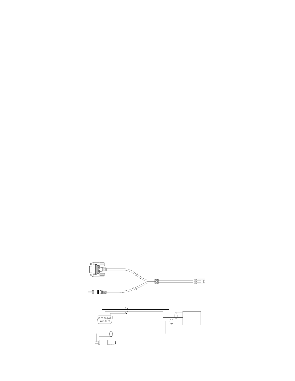
6. PS28/48 test cable part number 264564.
7. RCA to bare wire cables (to connect cube speakers to bass module).
Black rear cable part number 180644
Black Left/Center/Right part number 180643-4
Note: AC2 connector part number 195505-001 is needed to connect bare wire to Jewel® Cube
speaker.
9 PIN D-SUB FEMALE
Connect to computer
RS232 port
Connect to D-A
converter
RCA PLUG
2
3
6
7
8
Test cable part number 264564
1
8 PIN RJ45
RJ45
8 PIN
Connect to
PS28/48 bass module
Page 2

PS28/48 Performance Verification Procedures
(Without AV28 Media Center Console)
Test setup procedures
Place the bass module into TAP mode using
the procedures located at the end of this
document.
Note: Place all four DIP switches into the down
position before returning the unit to the customer.
Test cable part number 264564, Figure 16, is
needed to test the bass module.
Connect the D-sub, 9 pin connector on the test
cable to the COM port on your computer.
Connect the RJ-45, 8 pin connector to the
bass module.
The bass module requires a digital audio input.
Connect the analog output of an oscillator to
the analog input of an Analog to Digital (A-D)
converter. Connect the test cable’s RCA
connector to the A-D converter S/PDIF output.
2 Bass Module Air Leak Test
2.1 Apply a 200 mVrms, 40 Hz signal to the
input of the A-D converter.
2.2 Check for air leaks from the cabinet. Listen
near the areas where the plastic seals to the
wood.
3. Cube Speaker Phase Test
Note: The DC voltage should only be momen-
tarily applied to the cube speaker input to avoid
damaging the speakers.
3. 1 Observing polarity, momentarily apply 8 Vdc to
the input of the cube speaker.
3.2 The speakers should move outward with
the application of the dc voltage. Check the
cube wiring if it moves inward.
1. Sweep Test
1.1 Issue the following TAP commands:
SO ALL D (select all digital source inputs)
SP 5 (5 speaker mode)
VO CB 0 (set volume to full output, 0dB)
MU AMP OFF (unmute the amp)
1.2 Apply a 200 mVrms, 25 Hz signal to the left
and right input of the analog to digital (A-D)
converter. Listen for any extraneous noises
such as rubbing, scraping, or ticking.
Note: No extraneous noises such as rubbing,
scraping or ticking should be heard. To distinguish between normal suspension noise, rubs
and ticks, displace the woofer cone with your
finger. If the sound can be made to go away or
get worse, it’s a rub or tick and the woofer
should be replaced. If the noise stays the
same, it’s normal suspension noise and it will
not be heard with regular program material.
1.3 Sweep the bass module from 40 Hz to 300 Hz.
Listen carefully for any buzzes, rattles
or extraneous noises coming from the bass
module.
Note: Redress any wire or component that
buzzes.
4. Cube Speaker Sweep Test
4.1 Apply an 11 Vrms, 20 Hz signal to the
input of the satellite. Change the applied signal
to 8 Vrms, 150 Hz. Sweep the oscillator from
150 Hz to 2 kHz.
4.2 Listen for rubs, ticks, air leaks, buzzes or
other extraneous noises.
Note: Defects such as rubs, ticks and air leaks
will typically be most audible during the 20 Hz
test. Defects such as buzzes will typically be
heard during the 150 Hz to 2 kHz sweep.
Note: The satellite cubes are not repairable.
The Jewel Cube® speakers are repairable.
5. Listening Test
5.1 Connect the cube speakers to the outputs
of the bass module.
5.2 Connect an audio source (i.e. CD player)
to the input of the A-D converter.
5.3 Perform procedure 1.1
5.4 Adjust the volume output of the audio
source to a comfortable level and listen for a
clean undistored audio output from the bass
module and cube speakers.
2
Page 3

PS28/48 Performance Verification Procedures
(With AV28 Media Center Console)
Test Setup
®
Using the Lifestyle
cable part number 260351-001, connect the
AV28 media center to the PS28/48 bass
module.
1. Sweep Test
1.1 Apply a 200 mVrms, 25 Hz signal to the left
and right AUX input of the AV28 media center.
Adjust the AV28 media center to full volume.
Listen for any extraneous noises such as
rubbing, scraping, or ticking coming from the
bass module.
Note: No extraneous noises such as rubbing,
scraping or ticking should be heard. To distinguish between normal suspension noise, rubs
and ticks, displace the woofer cone with your
finger. If the sound can be made to go away or
get worse, it’s a rub or tick and the woofer
should be replaced. If the noise stays the
same, it’s normal suspension noise and it will
not be heard with regular program material.
1.2 Sweep the bass module from 40 Hz to 300 Hz.
Listen carefully for any buzzes, rattles
or extraneous noises coming from the bass
module.
Note: Redress any wire or component that
buzzes.
2 Bass Module Air Leak Test
2.1 Apply a 200 mVrms, 40 Hz signal to the
AUX input of the AV28 media center.
2.2 Check for air leaks from the bass module
cabinet. Listen near the areas where the plastic
seals to the wood.
28/48 system’s audio input
3. Cube Speaker Phase Test
Note: The DC voltage should only be momen-
tarily applied to the cube speaker input to avoid
damaging the speakers.
3. 1 Observing polarity, momentarily apply 8 Vdc to
the input of the cube speaker.
Note: Connect the positive side of the dc
supply to the positive input of the cube. Connect the negative side of the dc supply to the
negative input of the cube speaker.
3.2 The speakers should move outward with
the application of the dc voltage. Check the
cube wiring if it moves inward.
4. Cube Speaker Sweep Test
4.1 Apply an 11 Vrms, 20 Hz signal directly to
the input of the satellite. Change the applied
signal to 8 Vrms, 150 Hz and the sweep the
oscillator from 150 Hz to 2 kHz.
4.2 Listen for rubs, ticks, air leaks, buzzes or
other extraneous noises.
Note: Defects such as rubs, ticks and air leaks
will typically be most audible during the 20 Hz
test. Defects such as buzzes will typically be
heard during the 150 Hz to 2 kHz sweep.
Note: The satellite cubes are not repairable.
The Jewel
5. Listening Test
5.1 Connect the cube speakers to the outputs
of the bass module.
5.2 Adjust the volume to a comfortable level
and listen for a clean undistored audio output
from the bass module and cube speakers.
Cube® speakers are repairable.
3
Page 4

Setting up a computer to issue TAP commands
1. Open a terminal window. Click: Start/Pro-
gram/Accessories/Hyperterminal/Hyperterminal
2. In the “Connection Description” window, type
the name “LS28, 35 bass module test” then
click “OK”; any name may be entered.
3. In the “Connect To” window, select the COM
port on your computer that you will be connecting the bass module to and then click OK.
4. In the “COM1 Properties” window, make the
selections in the various fields as shown.
5. In the Hyper Terminal window, click on File/
Properties. In the Properties window, click on
the Settings tab, make the selections in the
various fields as shown.
6. In the Settings window, click on
ACSII setup and make the selections and changes as shown
4
Page 5

Placing the Bass Module into TAP Mode
! Place all four DIP switches to the down position before returning the unit to the customer !
1. Place the bass module into TAP mode
1.1 Set all four DIP switches into the “up”
position. Apply power to the bass module using
the AC line switch and wait until the amber
LED blinks twice and the green LED blinks
briefly at least once (approximately 3 seconds
after power up). Then, within twenty seconds,
flip ALL four switches down, then flip switch #4
(closest to the RJ-45 connector) back up. The
unit will now communicate in TAP mode. The
amber and green LED will blink alternately
when no S/PDIF signal is applied. Note that
when TAP mode is activated in this manner, the
DSP will echo characters sent by the terminal.
UP
12
3
4
Down
2. Verify the bass module communicates in
TAP mode.
2.1 Connect the test cable’s, part number
264564, DB-9 connector to the RS-232 COM
port on your computer. Connect the test cable’s
RJ-45 connector to the bass module.
2.2 Type the command ST S and hit “Enter”.
The following response should be seen on your
computer screen. The results may differ depending on the unit settings. If no S/PDIF signal
is applied, the sample rate will be 29 kHz.
SAMPLE RATE : 44101.30
SPKR TYPE : 02
DIP VALUE : 1111
LCRB_MUTE : 1
LSRS_MUTE : 1
SAT_CLIP : 1
BASS_CLIP : 1
EURO_BASS : 1
EURO_TREBLE: 0
Figure 15. DIP switch Up/Down orientation
Equalizer Programming Method
Type the equalization setup command
SE [SPEAKER TYPE], [EUROPEAN BASS],
[EUROPEAN TREBLE]
ConditionCommand
SPEAKER
TYPE
SE F = falcon ON/OFF ON/OFF
D = doubleshot
C = cricket
B = dublin
M = mariner
U = Installer
EURO
BASS
EURO
TREBLE
2.3 Check the software by typing (issuing) the
command TN 4 and then hitting “Enter”. A
typical response would be as follows.
03DE6455, 010808
03DE6455 is the checksum
010808 is the software version
Verify the changes have been made by typing
the command ST S.
The speaker type (SPKR TYPE) and other
information will be displayed. Decode the
numerical two digit speaker type as follows.
00 Falcon (Early version dual cube)
01 Doubleshots (Later version dual cube)
02 Cricket (Jewel® Cube)
03 Dublin (Single Cube)
04 Mariner (151 environmental speakers)
05 User EQ (Installer)
Example: To set the equalization to cricket
cubes, euro bass off and euro treble off, type
the command as follows. SE C,OFF,OFF
5
 Loading...