

Bose Lifestyle 48 Series IV, Lifestyle 38 Series IV, LIFESTYLE DVD Series Owner's Manual
Owner’s Guide
Guía de usario
Notice d’utilisation
LIFESTYLE
®
DVD
HOME ENTERTAINMENT SYSTEMS
WITH THE VS-2 VIDEO ENHANCER
ii
EnglishTAB 6TAB 8 TAB 7 TAB 3TAB 5 TAB 2TAB 4
SAFETY INFORMATION
Please read this guide
Please take the time to follow the instructions in this guide
carefully. They will help you set up and use your system
properly so you can enjoy all of the advanced features. Please
save this guide for future reference.
WARNINGS:
The lightning flash with arrowhead symbol within an
equilateral triangle alerts the user to the presence of
uninsulated, dangerous voltage within the system
enclosure that may be of sufficient magnitude to constitute a
risk of electric shock.
The exclamation point within an equilateral triangle alerts
the user to the presence of important operating and
maintenance instructions in this guide.
• To reduce the risk of fire or electrical shock, do not expose
the product to rain or moisture.
• Do not expose this apparatus to dripping or splashing, and
do not place objects filled with liquids, such as vases, on or
near the apparatus. As with any electronic products, use
care not to spill liquids into any part of the system. Liquids
can cause a failure and/or a fire hazard.
• Do not place any naked flame sources, such as lighted
candles, on or near the apparatus.
CAUTIONS:
• Use of controls or adjustments or performance of procedures other than those specified herein may result in
hazardous radiation exposure. The compact disc player
should not be adjusted or repaired by anyone except
properly qualified service personnel.
• Make no modifications to the system or accessories.
Unauthorized alterations may compromise safety, regulatory compliance, and system performance, and may void
the warranty.
Additional safety information
See the additional instructions on the
Important Safety
Information
sheet enclosed in the shipping carton.
Note:
• Where the mains plug or appliance coupler is used as the
disconnect device, such disconnect device shall remain
readily operable.
• The product must be used indoors. It is neither designed
nor tested for use outdoors, in recreation vehicles, or on
boats.
• This product is intended to be used only with the power
supply provided.
00.LIV_IG.book Page ii Monday, January 12, 2009 10:58 AM
iii
TAB 5TAB 4TAB 6TAB 8TAB 7English TAB 3TAB 2
Class 1 laser product
This CD/DVD player is classified as a
CLASS 1 LASER PRODUCT according
to EN 60825-1:1994+A1+A2,
IEC60825-1:1993+A1+A2.
Class B emissions
• This Class B digital apparatus meets all requirements of the
Canadian Interference-Causing Equipment Regulations
(Canada only).
• If applicable, the radio communication device incorporated
into this apparatus meets all requirements of the
Industry Canada standard RSS-310 (Canada only).
This product conforms to the EMC Directive 2004/108/EC and
to the Low Voltage Directive 2006/95/EC. The remote control
conforms to the RTTE Directive 99/5/EC. The complete
Declaration of Conformity can be found at:
www.
Bose
.com/static/compliance/index.html.
Batteries
Please dispose of used batteries properly, following any local
regulations. Do not incinerate.
Important product registration
Registering your product entitles you to receive free system
upgrades to keep your product performing optimally. It also
allows us to send you information about new products and
special offers from Bose.
Please follow the instructions on your Product Registration
card to register by mail, on the Internet, or by phone. Failure
to register will not affect your limited warranty rights.
For Your Records
Bose recommends that you record your system model
information here and the serial numbers both here and on
your Product Registration Card.
Serial numbers are located on the bottom of the media
center and the VS-2, and on the connection panel of the
Acoustimass
®
module.
System model name and number (on the carton):
LIFESTYLE® ______________________________ Series #______
Serial numbers:
Media center Ser Num: ____________________________________
VS-2 bar code: ___________________________________________
Acoustimass® module SN: _________________________________
Dealer name: ____________________ Dealer phone: _________
Purchase date: ___________________________________________
It may be helpful to keep your sales receipt and a copy of your
Product Registration card together with this guide.
CLASS 1 LASER PRODUCT
KLASSE 1 LASER PRODUKT
LUOKAN 1 LASER LAITE
KLASS 1 LASER APPARAT
00.LIV_IG.book Page iii Monday, January 12, 2009 10:58 AM
iv
EnglishTAB 6TAB 8 TAB 7 TAB 3TAB 5 TAB 2TAB 4
CONTENTS
INTRODUCTION 2
Welcome . . . . . . . . . . . . . . . . . . . . . . . . . . . . . . . 2
Simplifying your setup . . . . . . . . . . . . . . . . . . . . . 3
Unpacking the carton . . . . . . . . . . . . . . . . . . . . . . 3
SYSTEM SETUP 6
1 Choosing locations for the system . . . . . . . . . . . . 6
Arranging the system around your room . . . . . . . 7
Positioning the front and center speakers . . . . 7
Positioning the rear speakers . . . . . . . . . . . . . . 8
Arranging the media center and VS-2 . . . . . . . 9
Positioning the Acoustimass
®
module . . . . . . . 10
Looking over your finished placement . . . . . . . 12
COMPLETE SYSTEM CONNECTIONS 13
2 Connecting speaker cables . . . . . . . . . . . . . . . . . 13
Connecting all of the speakers . . . . . . . . . . . . . . 14
3 Connecting the module . . . . . . . . . . . . . . . . . . . . 16
4 Connecting the media center . . . . . . . . . . . . . . . . 19
5 Disconnecting your devices from the TV . . . . . . . 25
6 Connecting your TV . . . . . . . . . . . . . . . . . . . . . . . 26
If an HDMI connection is not possible . . . . . . . 28
7 Connecting another device
(cable or satellite box, VCR, or DVR) . . . . . . . . . . 29
Connecting the video from your cable
or satellite box first . . . . . . . . . . . . . . . . . . . . . . . 30
Adding audio from your cable or satellite box . 32
Including a digital audio connection . . . . . . . . 33
Adding more devices . . . . . . . . . . . . . . . . . . . . 34
8 Attaching the IR emitter and TV sensor . . . . . . . 35
9 Connecting the AM and FM antennas . . . . . . . . 37
10 Connecting the system to power . . . . . . . . . . . . 39
11 Setting the remote to control your TV
and other devices . . . . . . . . . . . . . . . . . . . . . . . . 40
Inserting the remote batteries . . . . . . . . . . . . . . . 40
Making it a universal remote . . . . . . . . . . . . . . . . 41
Setting the remote for TV control . . . . . . . . . . . 41
Setting the remote for cable or satellite . . . . . . 44
Setting the remote for another device . . . . . . . 46
12 Tailoring the sound to your room . . . . . . . . . . . . 47
Getting the sound you want. . . . . . . . . . . . . . . . . 47
Beginning the process . . . . . . . . . . . . . . . . . . . 48
Finishing the process . . . . . . . . . . . . . . . . . . . . 49
Storing any parts you do not need . . . . . . . . . . . 49
USING AND ENJOYING YOUR SYSTEM 50
Introducing the basics . . . . . . . . . . . . . . . . . . . . . .50
Turning on the system . . . . . . . . . . . . . . . . . . . . 50
Turning on your TV . . . . . . . . . . . . . . . . . . . . . . . 50
00.LIV_IG.book Page iv Monday, January 12, 2009 10:58 AM

CONTENTS
v
TAB 5TAB 4TAB 6TAB 8TAB 7English TAB 3TAB 2
Getting the sound for your video . . . . . . . . . . . . . 50
Getting the video to appear . . . . . . . . . . . . . . . . . 50
Using the system controls . . . . . . . . . . . . . . . . . . . . 51
An introductory overview . . . . . . . . . . . . . . . . . 51
The remote control . . . . . . . . . . . . . . . . . . . . . . 51
The media center . . . . . . . . . . . . . . . . . . . . . . . 52
USING THE VARIOUS SOURCES 53
Playing a disc . . . . . . . . . . . . . . . . . . . . . . . . . . . . 53
Cleaning discs . . . . . . . . . . . . . . . . . . . . . . . . . 53
To control play . . . . . . . . . . . . . . . . . . . . . . . . . 54
Discs that are system compatible . . . . . . . . . . 54
Using the radio . . . . . . . . . . . . . . . . . . . . . . . . . . 55
To change stations . . . . . . . . . . . . . . . . . . . . . . 55
Using radio station presets . . . . . . . . . . . . . . . . 55
Using your TV, cable, satellite, DVR, or VCR . . . . 56
To control play . . . . . . . . . . . . . . . . . . . . . . . . . 56
MAKING LONG- OR SHORT-TERM
ADJUSTMENTS 57
Changing system and source settings . . . . . . . . 57
Long-term system adjustments . . . . . . . . . . . . 57
Short-term source settings . . . . . . . . . . . . . . . . 57
Changing the on-screen language . . . . . . . . . . . . 58
Other system options . . . . . . . . . . . . . . . . . . . . 59
Adjusting the audio timing . . . . . . . . . . . . . . . . . . 61
Settings options . . . . . . . . . . . . . . . . . . . . . . . . . . 62
REFERENCE 64
Connections: For TVs requiring SCART
(in Europe, only) . . . . . . . . . . . . . . . . . . . . . . . . . . . . 64
More about DVD play . . . . . . . . . . . . . . . . . . . . . . 67
To repeat a segment of the DVD . . . . . . . . . . . . 67
Setting DVD Parental Control . . . . . . . . . . . . . . 67
Maintaining the system . . . . . . . . . . . . . . . . . . . . . 69
Protecting and keeping it clean . . . . . . . . . . . . . 69
Checking your remote control response . . . . . . 69
Replacing the remote control batteries . . . . . . . 70
Changing remote control switch settings . . . . . 71
Setting up other rooms with sound . . . . . . . . . . . 73
Bose
®
link-compatible products
make it easy . . . . . . . . . . . . . . . . . . . . . . . . . . . . 73
Troubleshooting . . . . . . . . . . . . . . . . . . . . . . . . . . 74
Contacting Bose . . . . . . . . . . . . . . . . . . . . . . . . . . 79
Limited Warranty . . . . . . . . . . . . . . . . . . . . . . . . . 79
Technical information . . . . . . . . . . . . . . . . . . . . . . 80
END USER LICENSE AGREEMENT . . . . . . . . . . . 82
00.LIV_IG.book Page v Monday, January 12, 2009 10:58 AM
2
EnglishTAB 6TAB 8 TAB 7 TAB 3TAB 5 TAB 2TAB 4
INTRODUCTION
Welcome
Thank you for purchasing this Bose® LIFESTYLE® DVD
home entertainment system. This elegant and easy-touse system delivers superior performance for both
music and video program content.
With its many innovations, this system includes the
VS-2 video enhancer that provides HDMI
TM
video
connectivity and convenient video switching.
Among the advanced features you can discover:
• HDMI video inputs and output to your TV
• Automatic video switching provided by the VS-2
video enhancer
• Proprietary ADAPTiQ
®
audio calibration system that
tailors system audio for optimal performance in the
room where your system is located
• Expansion capabilities that let you add to your
system in up to 13 other rooms
00.LIV_IG.book Page 2 Monday, January 12, 2009 10:58 AM
3
INTRODUCTION
TAB 5TAB 4TAB 6TAB 8TAB 7English TAB 3TAB 2
Simplifying your setup
The detailed instructions that follow will guide you to:
• Set up the system where you want it.
• Connect all of its part.
• Make the right choice for connecting to your TV.
• Add external audio or video devices to the system.
• Custom tailor the sound to the profile of your room.
• Turn on and try out the system features and controls.
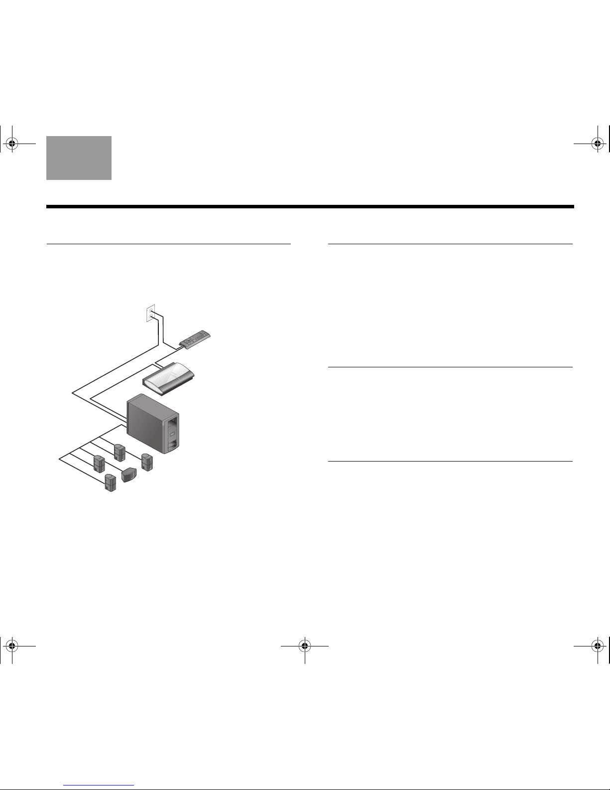
Unpacking the carton
Carefully unpack your system and save all of the
packing materials for safely shipping or transporting
the product.
If any part appears damaged, do not attempt to use it.
Notify Bose or your authorized Bose
®
dealer
immediately.
For Bose
®
contact information, refer to the address
sheet included in the carton.
Note: While unpacking, you can locate the system serial
numbers easily. Look on the bottom of the media center
and the VS-2 and near the connection panel on the
Acoustimass
®
module.
For future reference, we suggest that you record those
numbers in the space provided at the front of this book,
on page iii.
00.LIV_IG.book Page 3 Monday, January 12, 2009 10:58 AM
4
INTRODUCTION
EnglishTAB 6TAB 8 TAB 7 TAB 3TAB 5 TAB 2TAB 4
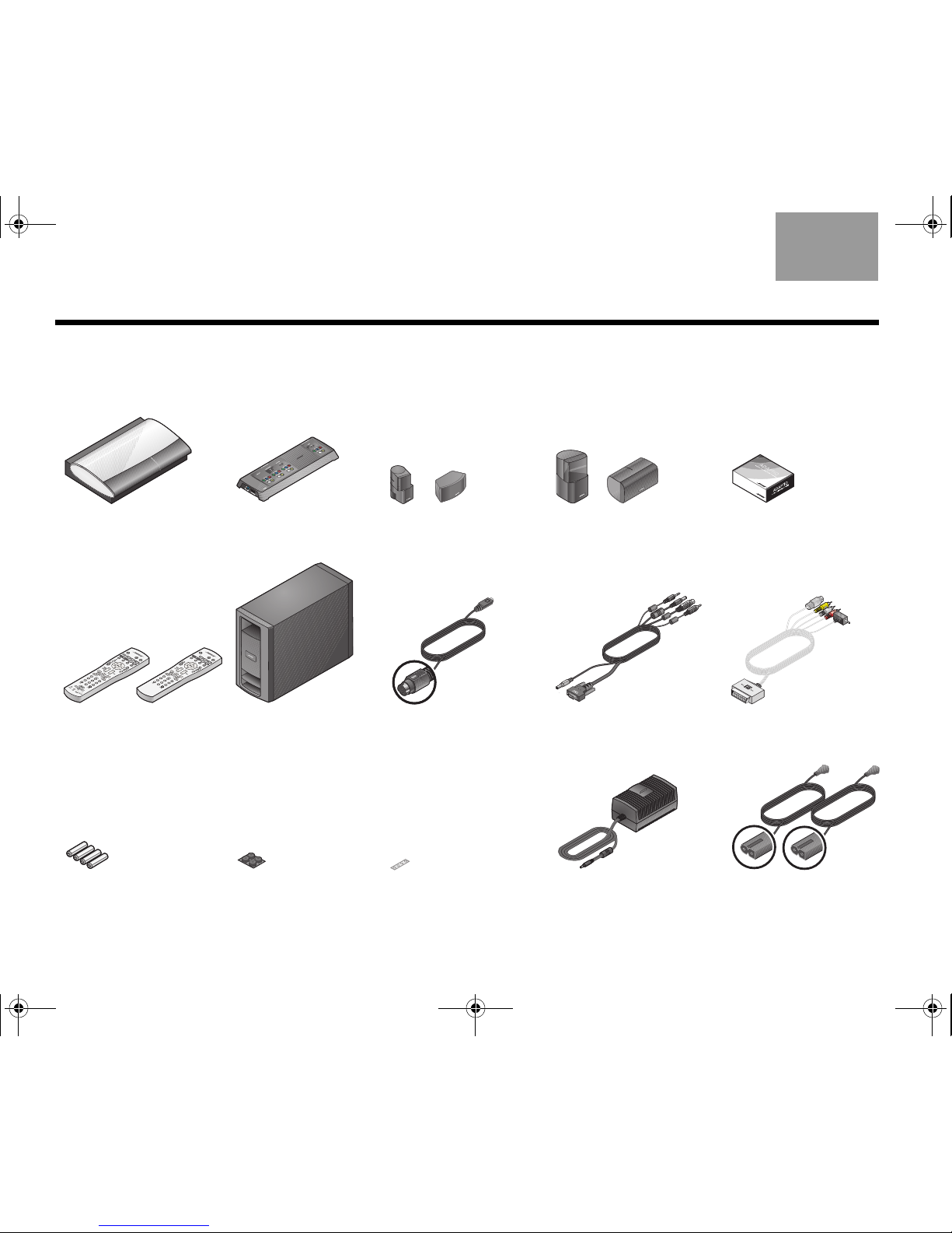
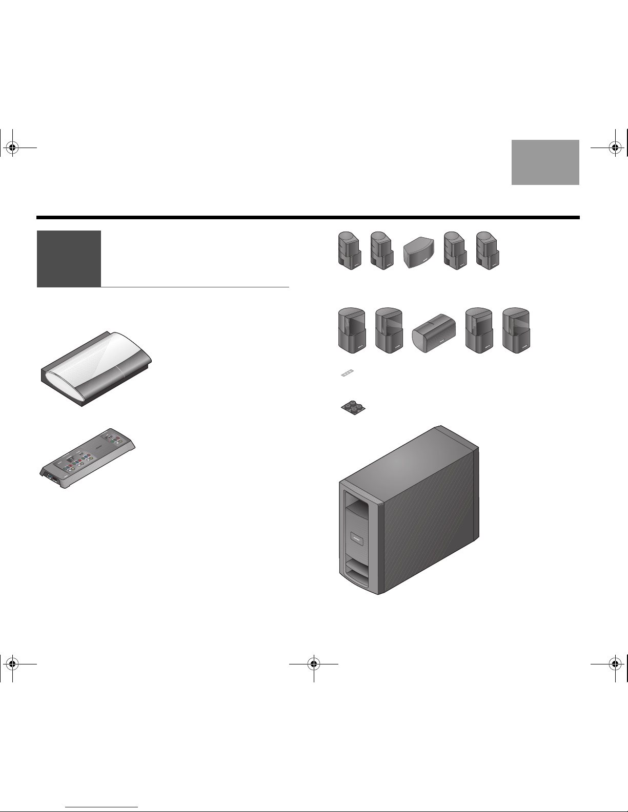
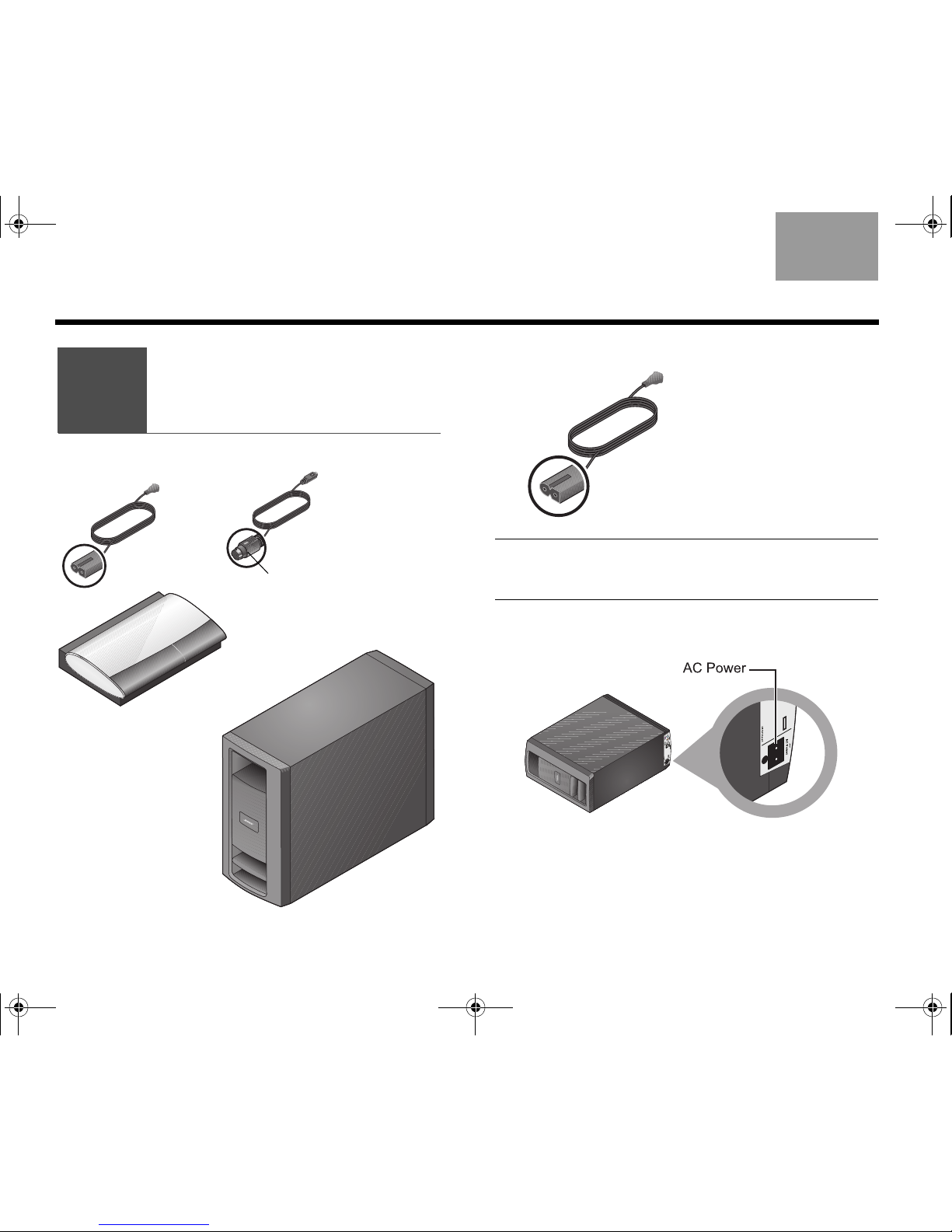
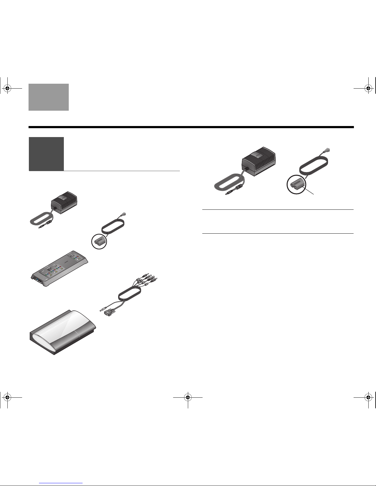
Included parts
As you unpack the carton, you can check to be sure it includes these parts.
❏ Media center ❏ VS-2
video enhancer
❏ Jewel Cube® .
speakers
❏ Direct/Reflecting
®
speakers
❏ ADAPTiQ
®
audio
calibration system
❏ Remote control ❏ Acoustimass
®
module
❏ Audio input cable ❏ VS-2 cable ❏ SCART adapter
(for Europe only)
❏ Remote control
batteries
❏ Acoustimass®
module rubber feet
❏ Speaker
rubber feet
❏ Power supply ❏ 2 AC power cords
LIFESTYLE® 35/48 OR
(4) (1)
LIFESTYLE® 28/38
(4) (1)
OR
LIFESTYLE®
38/48 28/35
00.LIV_IG.book Page 4 Monday, January 12, 2009 10:58 AM
5
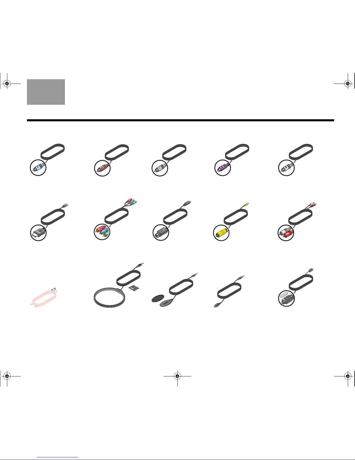
INTRODUCTION
TAB 5TAB 4TAB 6TAB 8TAB 7English TAB 3TAB 2
❏ Right
speaker cable
❏ Center
speaker cable
❏ Left
speaker cable
❏ Right Rear
speaker cable
❏ Left Rear
speaker cable
❏ HDMI™ cable ❏ Component video
cable
❏ S-Video cable ❏ Composite cable ❏ Stereo audio
cable
❏ FM antenna ❏ AM antenna ❏ TV on/off sensor ❏ IR emitter cable ❏ Optical audio
cable
Light Blue
Brown
White
Purple
Light Green
00.LIV_IG.book Page 5 Monday, January 12, 2009 10:58 AM
6
EnglishTAB 6TAB 8 TAB 7 TAB 3TAB 5 TAB 2TAB 4
SYSTEM SETUP
Choosing locations
for the system
1
What you need to use:
Media center
VS-2 video
enhancer
5 Jewel Cube® speakers
OR
5 Direct/Reflecting
®
speakers
Acoustimass
module
Center speaker
rubber feet
Acoustimass
®
module
rubber feet
05.LIV_SystemPlacement.fm Page 6 Thursday, January 15, 2009 4:29 PM
7
SYSTEM SETUP
TAB 5TAB 4TAB 6TAB 8TAB 7English TAB 3TAB 2
Arranging the system around
your room
For convenience in setting up your speakers, Bose
offers floor stands, table stands, and wall brackets. For
the rear speakers, we also offer a wireless connect kit.
To get further information or to order accessories, call
your Bose dealer. Or to contact Bose directly, refer to
the address list provided in the carton.
The images that follow show the speakers placed
without the use of brackets or stands.
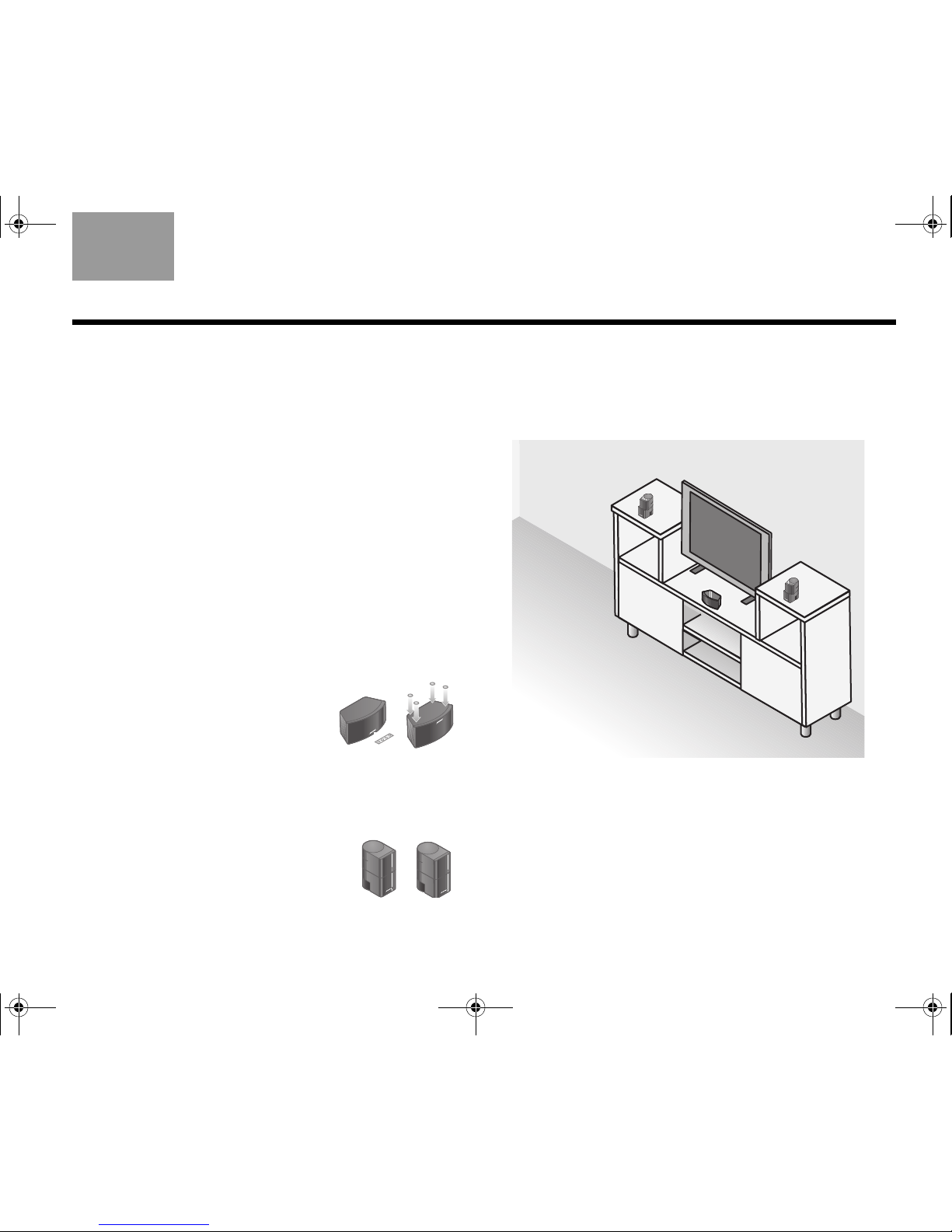
Positioning the front and center
speakers
These three front speakers center the dialogue and
create a broad stage of sound that matches what you
see on screen.
1. Attach the provided rubber feet
to the center speaker if it sits on
a surface like a shelf, a table, or
the TV.
2. Place the center speaker in a horizontal position on
a stable and level surface.
It can go above or below your TV.
3. Place one vertical speaker to the
left and one to the right of the TV.
Keep these left and right speakers within 3 ft (1 m)
of the TV screen, so the sound and picture work
together.
At the front of your room:
Make sure:
• Any speakers placed on a shelf are near the front
edge of the shelf.
Placing them farther back can change the tonal
quality of the sound.
F
ro
n
t
sp
e
a
k
e
r
s
L
e
f
t
C
e
n
te
r
R
i
g
h
t
00.LIV_IG.book Page 7 Monday, January 12, 2009 10:58 AM
8
SYSTEM SETUP
EnglishTAB 6TAB 8 TAB 7 TAB 3TAB 5 TAB 2TAB 4
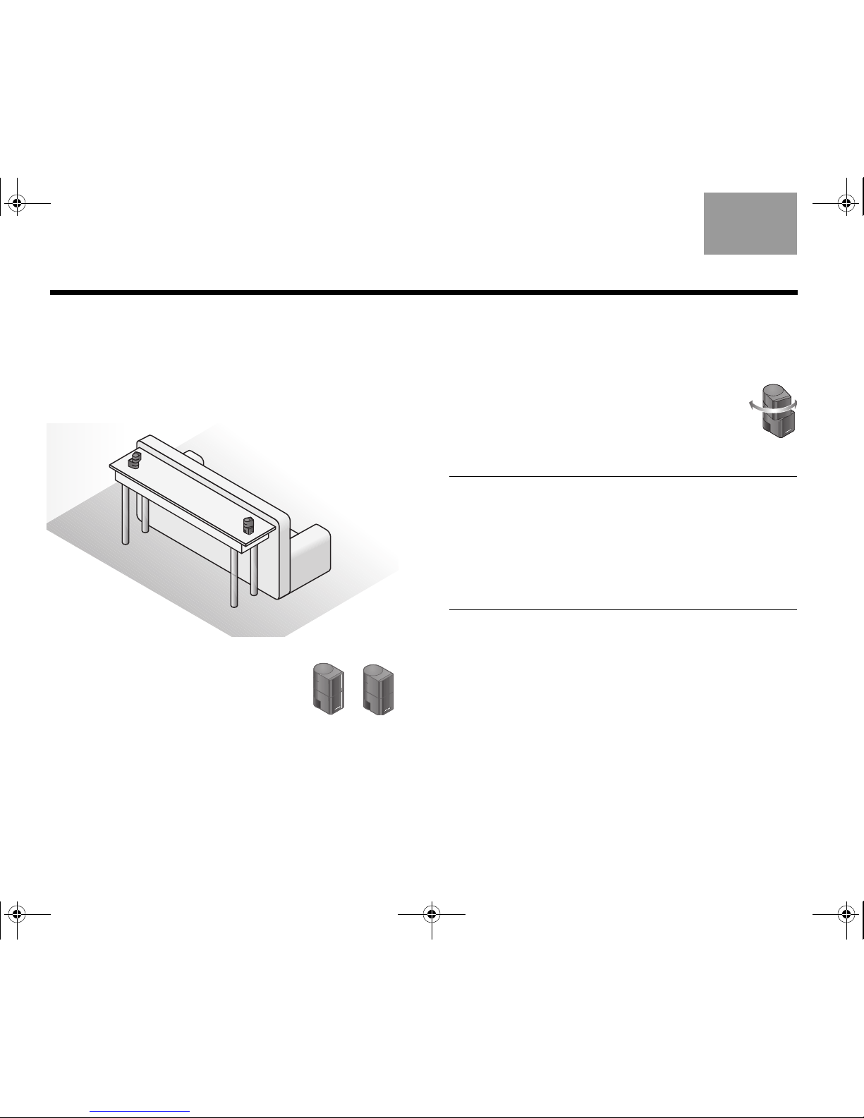
Positioning the rear speakers
These two speakers perform at the back of the room to
provide lifelike surround sound when it is needed for
special effects.
Toward the rear of your room:
1. Place one speaker to the left and
the other to the right of the viewers
and facing the front of the room.
Keep these two speakers as far
from the viewers as is practical.
2. Position each speaker at ear height (when seated)
or higher, if possible.
Make sure:
• To aim the speakers away from the listeners so the
source of the sound is not obvious.
• To rotate the top of all four of the vertical
speakers that are at the front and rear of
the room.
This helps create the lifelike sound your
system is designed to provide.
Note:
During placement, you may discover that you need
additional cables, which are available from your local
Bose dealer.
If you prefer to contact Bose directly, refer to the address
list provided in the carton, or visit Bose on the web at:
www.Bose.com.
R
e
a
r
s
p
e
a
k
e
r
s
L
e
f
t
R
i
g
h
t
00.LIV_IG.book Page 8 Monday, January 12, 2009 10:58 AM
9
SYSTEM SETUP
TAB 5TAB 4TAB 6TAB 8TAB 7English TAB 3TAB 2
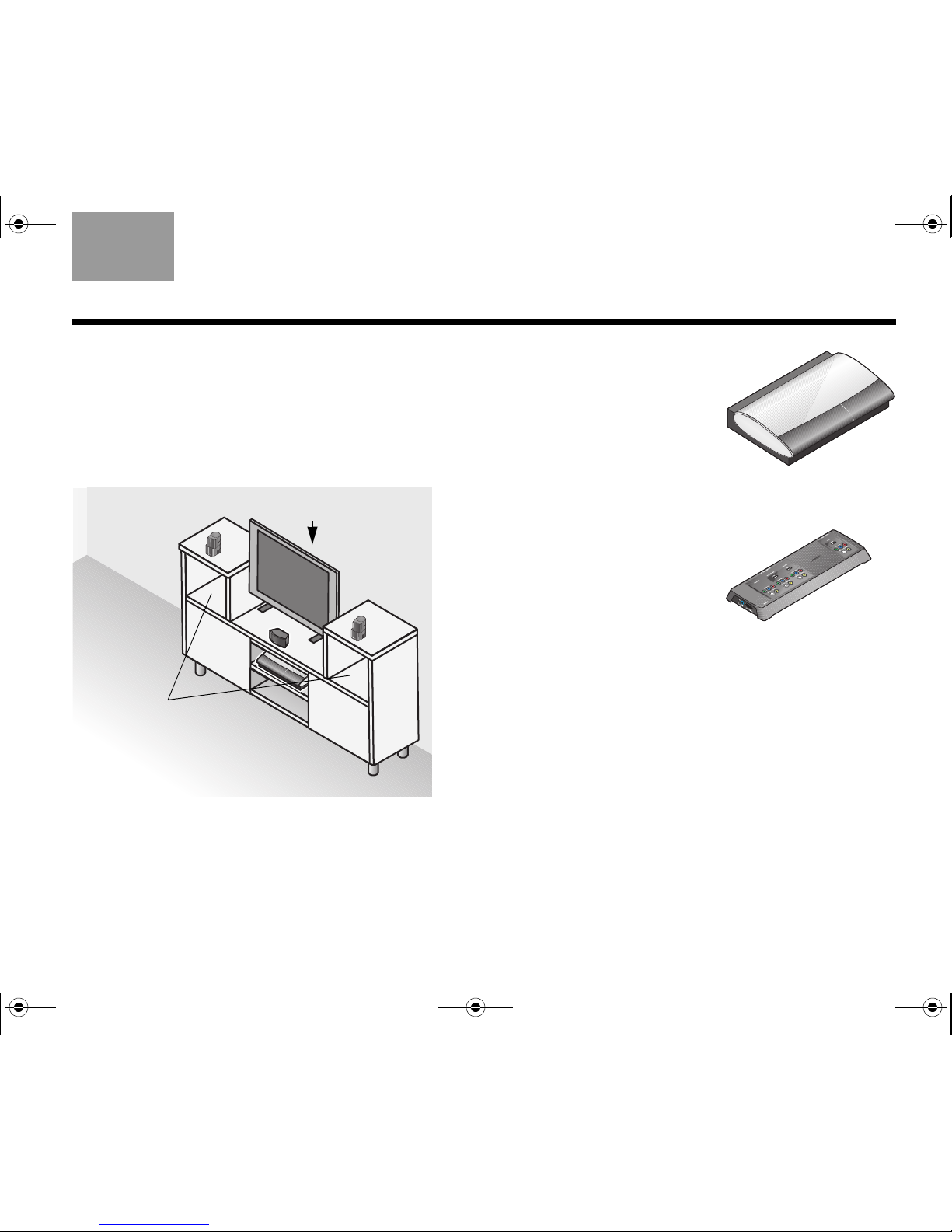
Arranging the media center and VS-2
Keep both the media center and VS-2 video enhancer
positioned for easy access in making connections.
When the connections are complete, you can move the
two units into final position.
With the VS-2 close to (behind) the media center:
1. Place the media center
on a flat, stable surface.
Allow space to lift the
front cover and open the
disc tray on the media
center. Also avoid
obstructions that block
your view of the front
display window.
2. Position the VS-2 behind
the media center – on
the floor, on an entertainment center shelf, or
mounted to the wall.
Make sure:
• The VS-2 and the media center are within 6 ft (1.8 m)
of each other.
• An AC power (mains) outlet is within 10 ft (3 m) of the
VS-2.
• The video cables from other devices (cable/satellite
box, DVR, VCR, or other) can reach the VS-2.
• The audio cables from these devices can reach the
media center.
M
e
d
i
a
c
e
n
t
e
r
Space for
other devices
V
S-
2
00.LIV_IG.book Page 9 Monday, January 12, 2009 10:58 AM

10
SYSTEM SETUP
EnglishTAB 6TAB 8 TAB 7 TAB 3TAB 5 TAB 2TAB 4
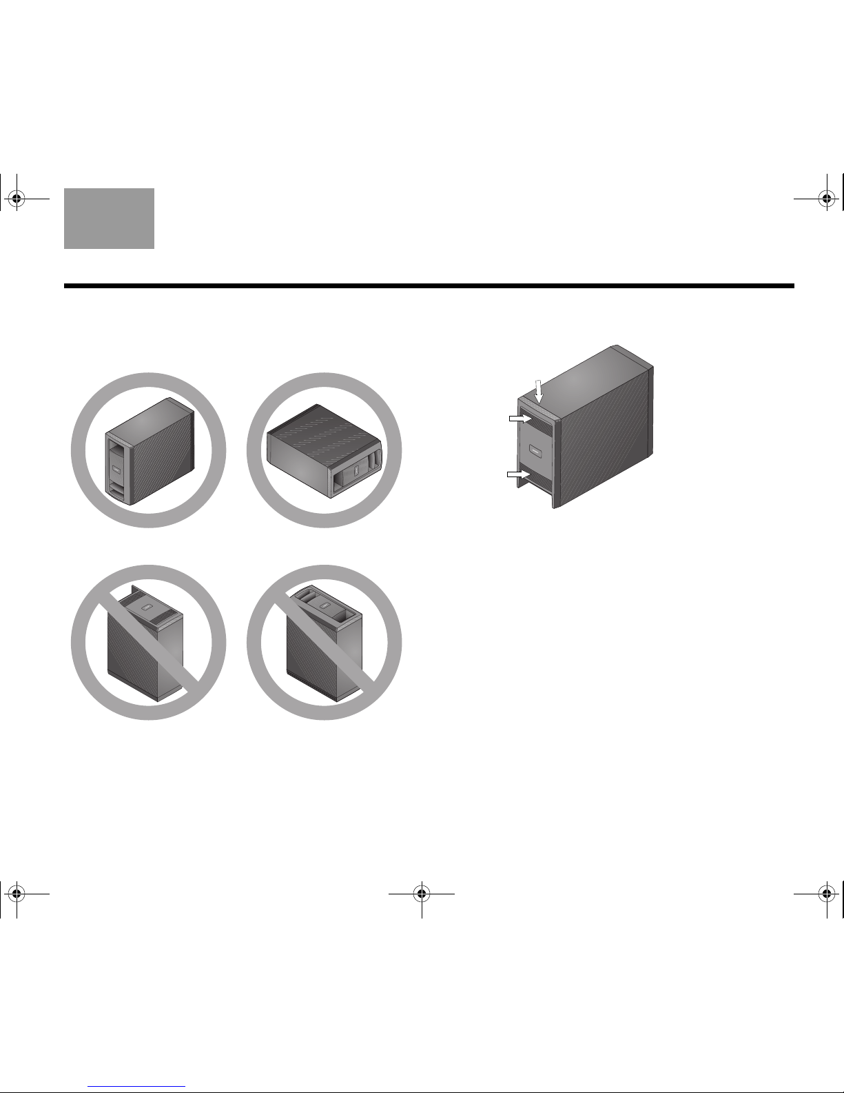
Positioning the Acoustimass® module
This speaker produces the deep bass sounds that
make you feel – not just hear – the on-screen action.
1. Attach the
four selfadhesive
rubber feet
to the bottom
surface of the
module.
These provide stability
and protect both the floor and the module.
Note: You may want to keep the module temporarily
standing on a side or upside down so you can make the
connections easily. When the connections are completed,
place the module in the location and position you have
chosen.
2. Place the module at the same end of the room as
your TV and the three front speakers.
You can place one side against a wall or position
the front facing into the room, NOT into a wall or
corner.
Avoid placing the module midway between two
walls or between the floor and ceiling.
Keep the module at least 18 in (.5 m) from your TV
to prevent interference and several feet (.8 m) from
audio or video tapes to prevent magnetic damage
to them.
3. Set the module on a side or the bottom surface,
but NOT standing on either end.
You can slide it behind a sofa or chair, under a
table, or behind drapes.
CAUTION: Do not block the ventilation openings on the
front and rear of the module.
Acoustimass
module
00.LIV_IG.book Page 10 Monday, January 12, 2009 10:58 AM
11
SYSTEM SETUP
TAB 5TAB 4TAB 6TAB 8TAB 7English TAB 3TAB 2
Ways to prevent ventilation blocking:
• Stand the module upright (BEST) or on a side
(ALTERNATE).
• DO NOT stand the module on either end.
• Place the module where the rear vents are open to air
flow.
Make sure:
• The module is NOT in an enclosure, on a bed or sofa,
or on a surface that can block the ventilation
openings.
• All speaker cables and the audio input cable from the
module can reach the rear of the module.
• An AC power (mains) outlet is within 10 ft (3 m) of the
module.
Rear of the
Acoustimass®
module
00.LIV_IG.book Page 11 Monday, January 12, 2009 10:58 AM
12
SYSTEM SETUP
EnglishTAB 6TAB 8 TAB 7 TAB 3TAB 5 TAB 2TAB 4
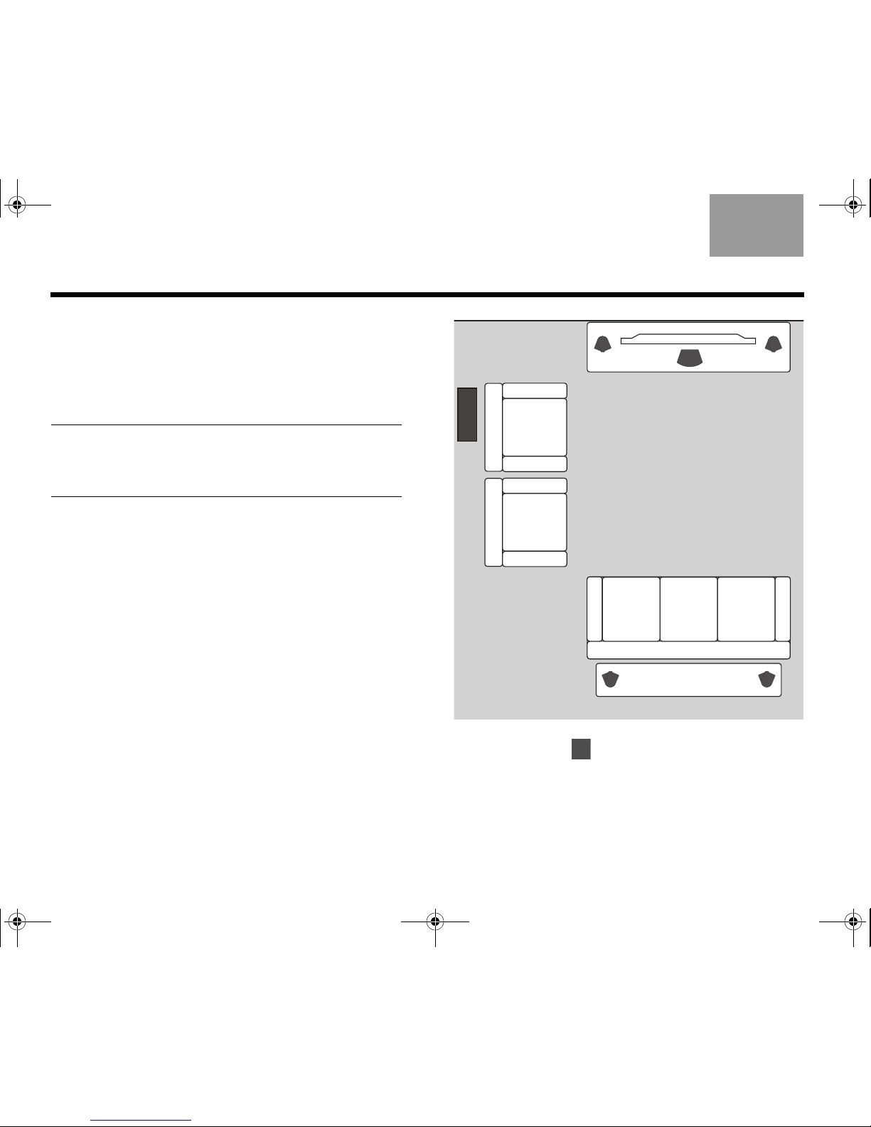
Looking over your finished placement
1. Check the overall arrangement of your system
components.
The speaker positions around the room should
follow a pattern similar to the one shown here.
Note: If you are using accessory stands or brackets with
the speakers, now is the time to follow the assembly
instructions for setting them up. The instructions include
how to wire and attach the speakers to your accessory.
2. Continue with on the next page to begin
connecting the system.
Left Center Right
Left rear Right rear
Acoustimass
®
module
TV
2
00.LIV_IG.book Page 12 Monday, January 12, 2009 10:58 AM
13
TAB 5TAB 4TAB 6TAB 8TAB 7English TAB 3TAB 2
Light blue
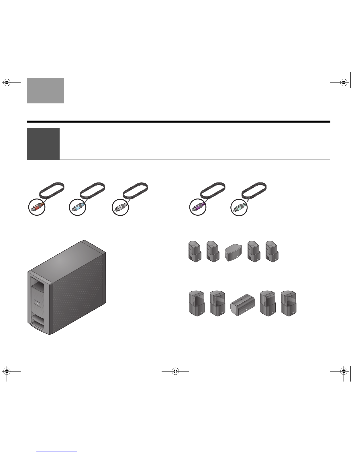
COMPLETE SYSTEM CONNECTIONS
What you need to use:
Jewel Cube® speakers
Direct Reflecting
®
speakers
Acoustimass
®
module
Front speaker cables
OR
Purple
Brown
White
Light green
R
e
a
r
s
p
e
a
k
e
r
c
a
b
l
e
s
Connecting speaker cables
2
00.LIV_IG.book Page 13 Monday, January 12, 2009 10:58 AM
14
COMPLETE SYSTEM CONNECTIONS
EnglishTAB 6TAB 8 TAB 7 TAB 3TAB 5 TAB 2TAB 4
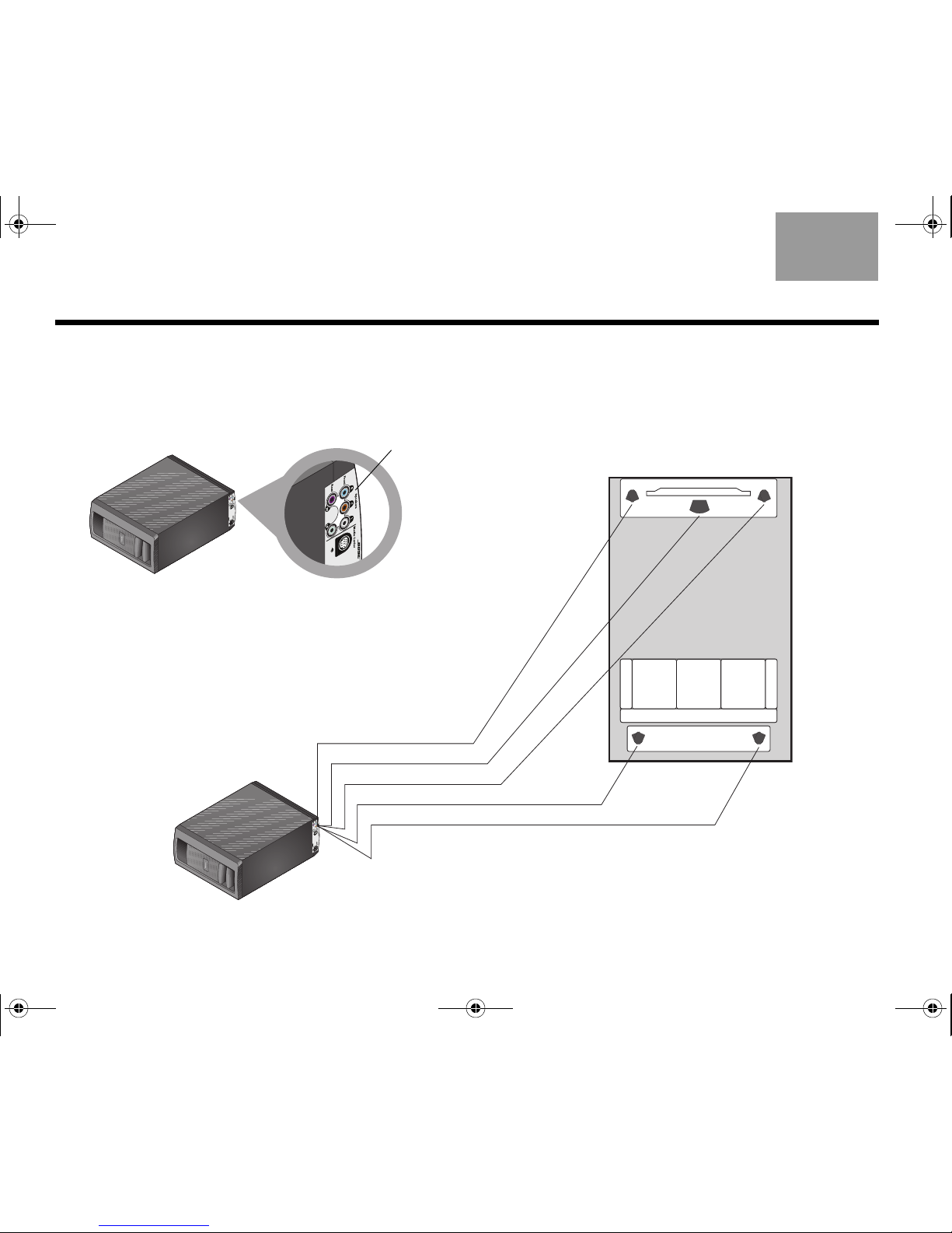
White to L
Brown to C
Light blue to R
Purple to RR
Left
speaker
(L)
Right
speaker
(R)
Center speaker
(C)
Right
rear
speaker
(RR)
Left
rear
speaker
(LR)
Light green to LR
Connecting all of the speakers
1. Locate the connection panel on the lower rear of
the Acoustimass
®
module.
2. Match the color on each connector to the speaker
cable plug of the same color and insert the plug
into the matching connector.
3. Notice the letters that identify the position of the
speakers in the room view on the right.
Colored
connectors
4. Route each cable from the Acoustimass module to
the proper speaker as shown.
Use the color on the plug that is inserted into the
module as your guide.
00.LIV_IG.book Page 14 Monday, January 12, 2009 10:58 AM
15
COMPLETE SYSTEM CONNECTIONS
TAB 5TAB 4TAB 6TAB 8TAB 7English TAB 3TAB 2
5. Use the letters L, C, R, LR, or RR marked on the
speaker end of each cable to verify which speaker
it connects to.
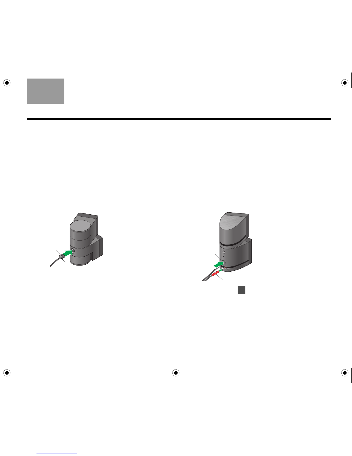
6. Connect this end to your speaker as follows.
For a Jewel Cube
®
speaker:
a. Hold the plug so the small key is on top.
b. Insert the plug firmly into the connector on the
rear of the speaker.
c. Repeat this process with the remaining four
cables.
For a Direct/Reflecting
®
speaker:
a. Press the tab on the rear of the speaker to
expose the two connectors.
b. Insert the wire that has a red band into the red
connector marked +.
c. Insert the other wire into the connector that is
marked –.
d. Release the connector tab.
e. Repeat this process with the remaining four
cables.
7. Continue with on the next page to begin
connecting the media center.
Key
R
Red +
Red R
Ta b
3
00.LIV_IG.book Page 15 Monday, January 12, 2009 10:58 AM
16
COMPLETE SYSTEM CONNECTIONS
EnglishTAB 6TAB 8 TAB 7 TAB 3TAB 5 TAB 2TAB 4
1. Choose the AC power cord.
CAUTION: Do not plug the power cord into an AC
(mains) outlet until all connections to the system are
completed.
2. Locate the connector labeled AC Power on the
Acoustimass module connection panel.
What you need to use:
Acoustimass
®
module
Media
center
Audio
input cable
AC Power
cord
Arrow
Connecting
the module
3
00.LIV_IG.book Page 16 Monday, January 12, 2009 10:58 AM
17
COMPLETE SYSTEM CONNECTIONS
TAB 5TAB 4TAB 6TAB 8TAB 7English TAB 3TAB 2
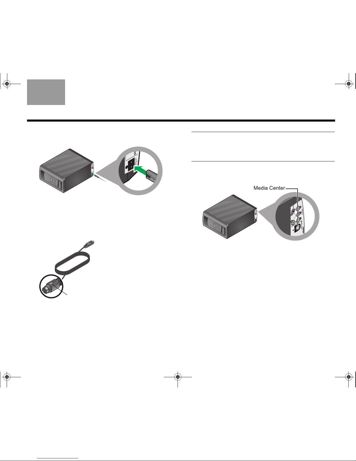
3. Insert the appropriate plug on the power cord into
the connector on the module.
4. Place the other end of the power cord near an
outlet, but do NOT plug it in at this time.
5. Choose the audio input cable that has an arrow on
the plug at each end.
CAUTION: Avoid putting strain on the plugs at either
end of the audio input cable. Pulling on the cable or
compressing it exerts excessive strain and can cause
damage.
6. Locate the connector labeled Media Center on the
Acoustimass
®
module connection panel.
Arrow
00.LIV_IG.book Page 17 Monday, January 12, 2009 10:58 AM
18
COMPLETE SYSTEM CONNECTIONS
EnglishTAB 6TAB 8 TAB 7 TAB 3TAB 5 TAB 2TAB 4
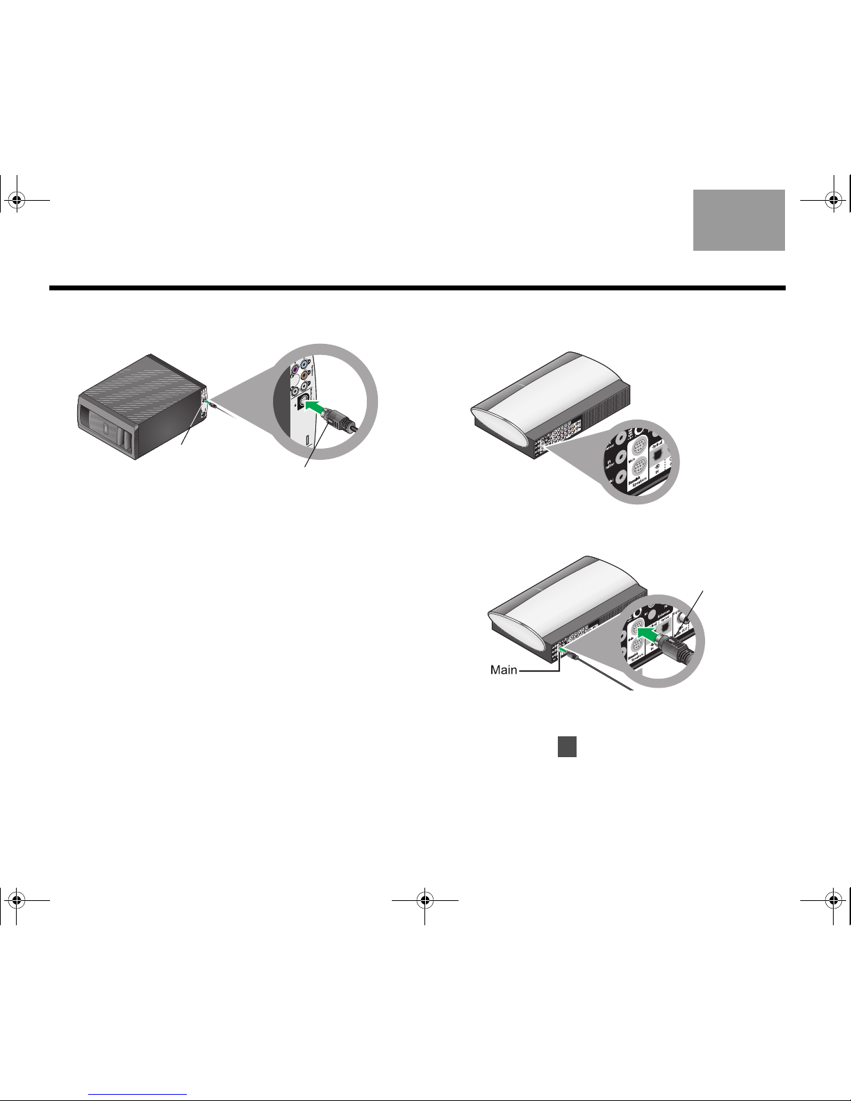
7. Insert the Audio input cable plug into this connector on the module.
Be sure the arrow on the flat side of the plug faces
the inner edge of the module.
All cables are now connected to the module. This
is a good opportunity to set the module upright or
on a side and move it into final position in your
room.
8. Locate the two connectors labeled Speakers on
the rear of the media center.
9. Insert the remaining plug on the audio input cable
into the top connector labeled Main.
Be sure that the arrow on the flat side of the plug is
facing up as you insert the plug.
10. Continue with on the next page for connections
to the VS-2 video enhancer.
Inner
edge
Arrow
Arrow
4
00.LIV_IG.book Page 18 Monday, January 12, 2009 10:58 AM
19
COMPLETE SYSTEM CONNECTIONS
TAB 5TAB 4TAB 6TAB 8TAB 7English TAB 3TAB 2
1. Choose the power supply and power cord.
CAUTION: Do not plug the power cord into an AC
(mains) power outlet until all connections to the system
are completed.
What you need to use:
VS-2 video enhancer
VS-2 cable
Media center
AC power cord
Power supply
Small end
Connecting
the media center
4
00.LIV_IG.book Page 19 Monday, January 12, 2009 10:58 AM
20
COMPLETE SYSTEM CONNECTIONS
EnglishTAB 6TAB 8 TAB 7 TAB 3TAB 5 TAB 2TAB 4
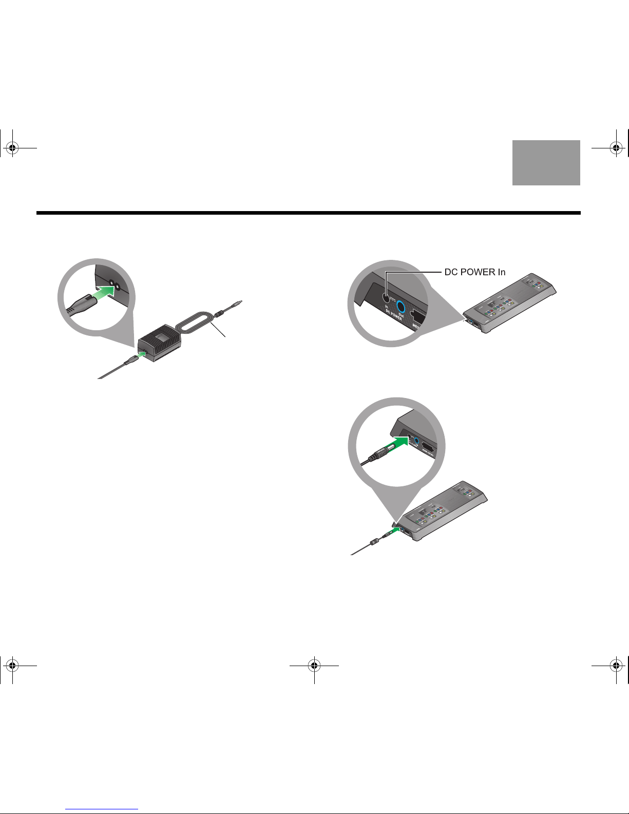
2. Plug the small end of the AC power cord into the
connector on the end of the DC power supply.
If you have a dual-voltage power supply:
MAKE SURE the voltage selection switch on the
bottom of the power supply is set properly for the
local power rating.
Check with local electrical authorities if you are not
sure of the appropriate power rating.
3. Place the other end of the power cord near an AC
power outlet, but do NOT plug it in at this time.
4. Locate the connector labeled DC POWER In on
one end of the VS-2 video enhancer.
5. Insert the power supply cable plug into the VS-2
connector.
Power
supply
cable
00.LIV_IG.book Page 20 Monday, January 12, 2009 10:58 AM
21
COMPLETE SYSTEM CONNECTIONS
TAB 5TAB 4TAB 6TAB 8TAB 7English TAB 3TAB 2
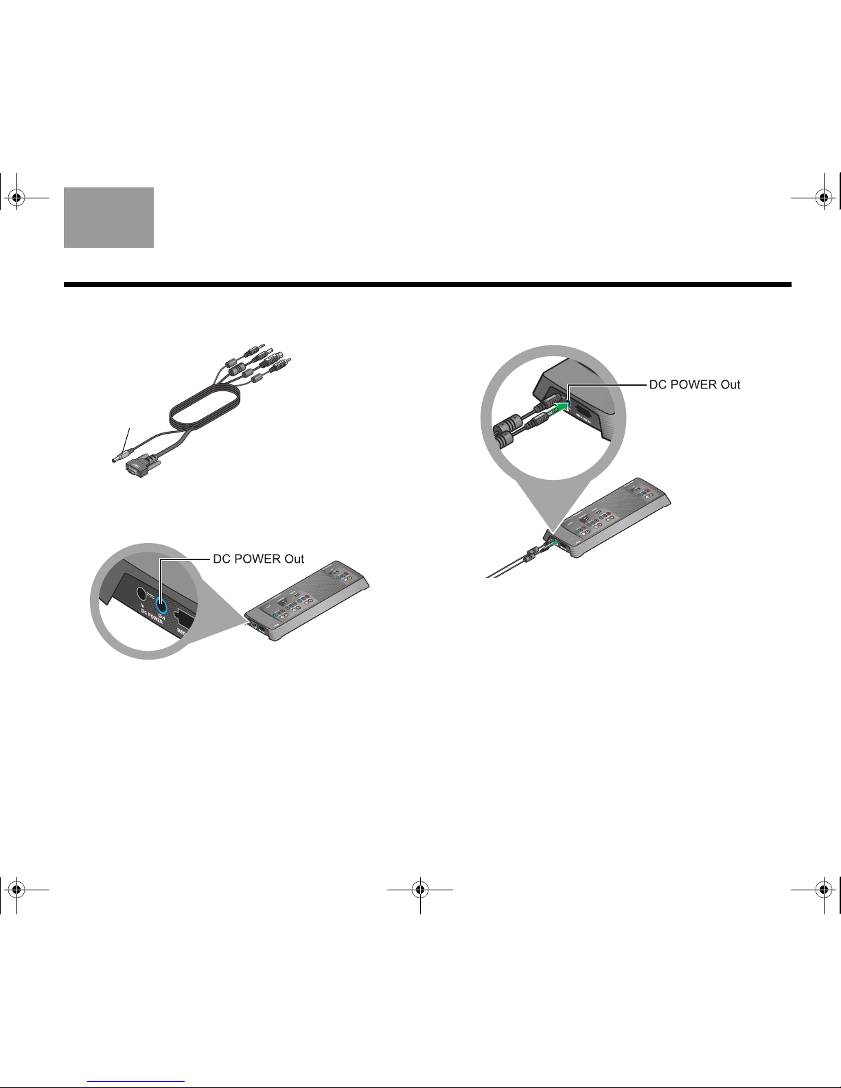
6. Choose the VS-2 cable and notice the small plug at
one end.
7. Locate the connector labeled DC POWER Out on
the VS-2 video enhancer.
8. Insert the gray plug labeled DC Power into this
connector.
Important Note: The two power cables that plug into
the end of the VS-2 contain antennas for the radio
frequency (RF) remote control.
BE SURE to fully extend both cables and keep them
away from other system cables as much as possible.
Small plug
00.LIV_IG.book Page 21 Monday, January 12, 2009 10:58 AM
22
COMPLETE SYSTEM CONNECTIONS
EnglishTAB 6TAB 8 TAB 7 TAB 3TAB 5 TAB 2TAB 4
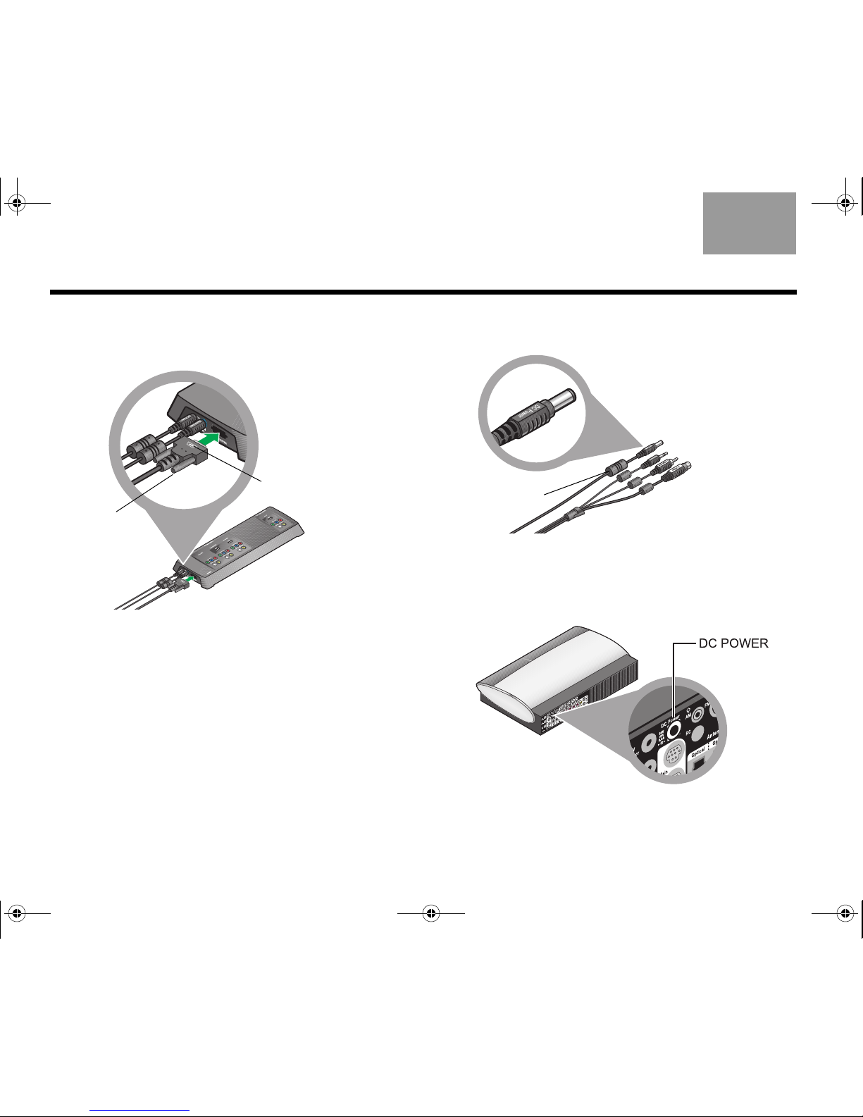
9. Attach the large plug on the cable, with the white
symbol facing up, into the remaining connector on
the VS-2 connector.
Be sure to tighten the thumb screws on either side
of the plug to secure it.
10. At the other end of the VS-2 cable, locate the plug
labeled DC power.
The cable for this plug has a large cylinder
attached.
11. On the rear of the media center, locate the
connector labeled DC Power.
White
symbol
Thumb
screw
Large
cylinder
00.LIV_IG.book Page 22 Monday, January 12, 2009 10:58 AM
23
COMPLETE SYSTEM CONNECTIONS
TAB 5TAB 4TAB 6TAB 8TAB 7English TAB 3TAB 2
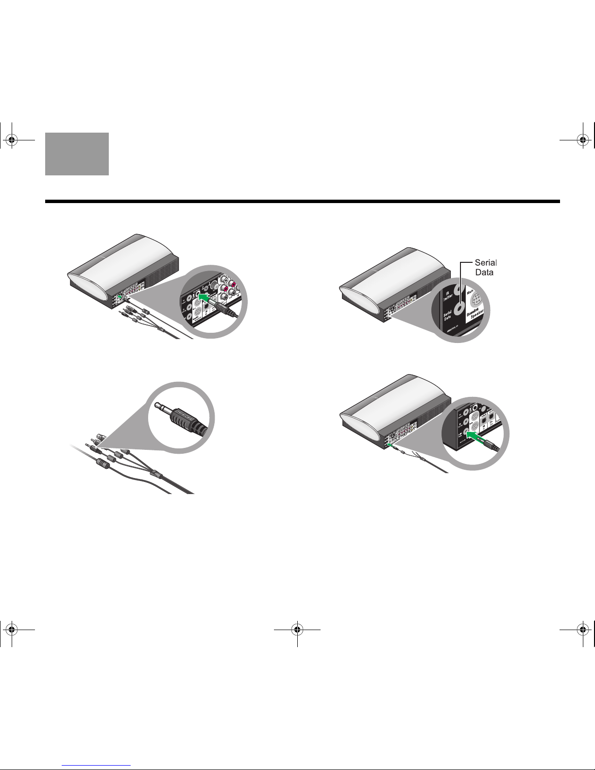
12. Insert the DC Power plug into this connector.
13. From the remaining three plugs on this cable,
choose the one labeled Serial Data.
14. Locate the connector labeled Serial Data on the
media center.
15. Insert the Serial Data plug into this connector.
00.LIV_IG.book Page 23 Monday, January 12, 2009 10:58 AM
24
COMPLETE SYSTEM CONNECTIONS
EnglishTAB 6TAB 8 TAB 7 TAB 3TAB 5 TAB 2TAB 4
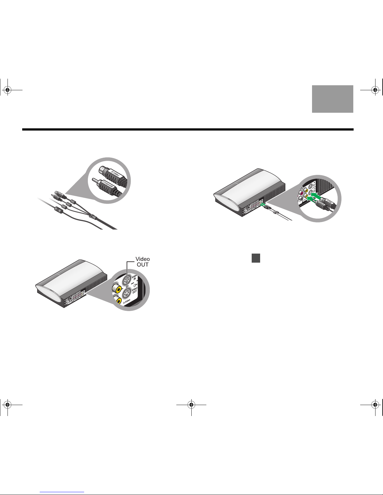
16. Notice that the two remaining plugs are labeled
Composite and S-Video.
17. On the rear panel of the media center, locate the
Video OUT connectors.
18. Insert the two video plugs, with their labels facing
up, into the appropriate Video OUT connectors on
the media center.
Check to be sure that the two cable plugs are
inserted into the lower Video OUT connectors, and
NOT into Video IN.
19. Continue with on the next page to begin
preparing your TV for use with the system.
5
00.LIV_IG.book Page 24 Monday, January 12, 2009 10:58 AM
25
COMPLETE SYSTEM CONNECTIONS
TAB 5TAB 4TAB 6TAB 8TAB 7English TAB 3TAB 2
• Leave the other end of the audio and video cables
connected to your video devices.
• Do NOT disconnect any antenna or power cables
from your TV.
Note: Later instructions will show you how to attach the
video cables from each device to the VS-2 connection
panel and the audio cables to the media center.
Disconnect all of the video devices, like a cable or
satellite box, from your TV.
• Remove both the audio and video cables at the TV
end only.
Disconnect video
and audio cables
from your TV
Disconnecting your
devices from the TV
5
00.LIV_IG.book Page 25 Monday, January 12, 2009 10:58 AM
26
COMPLETE SYSTEM CONNECTIONS
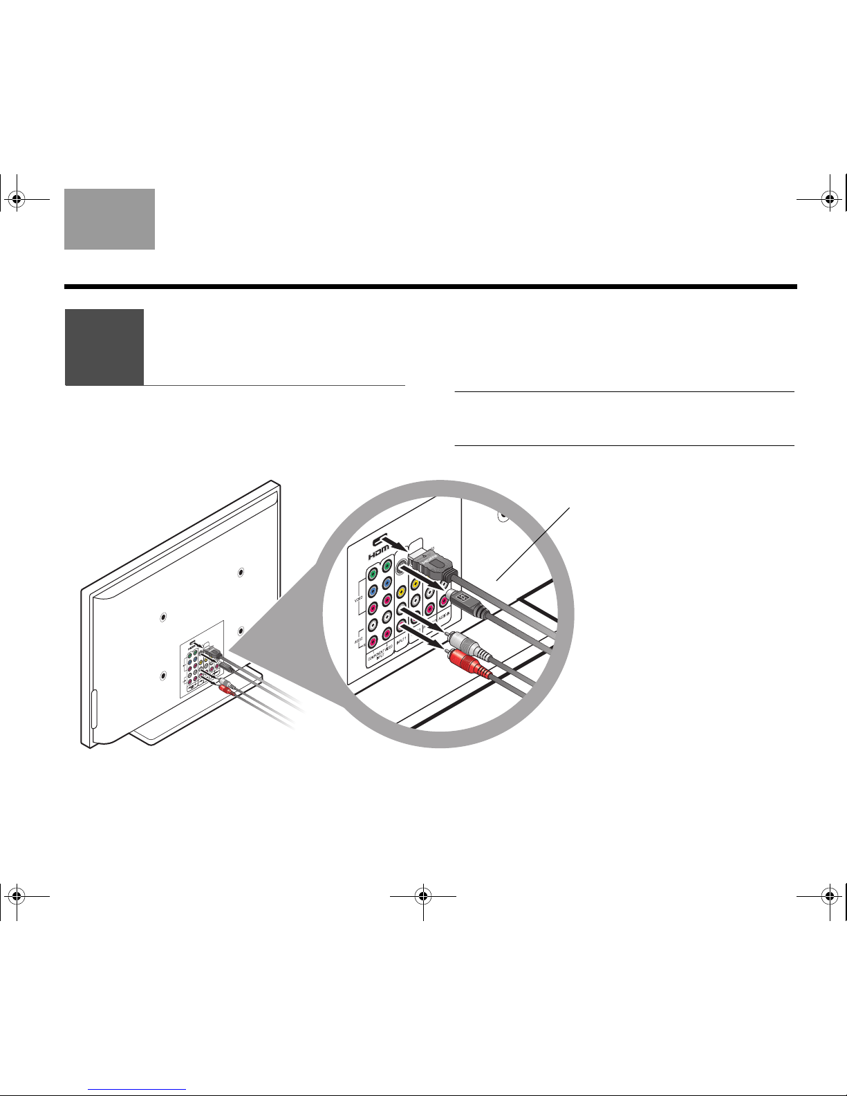
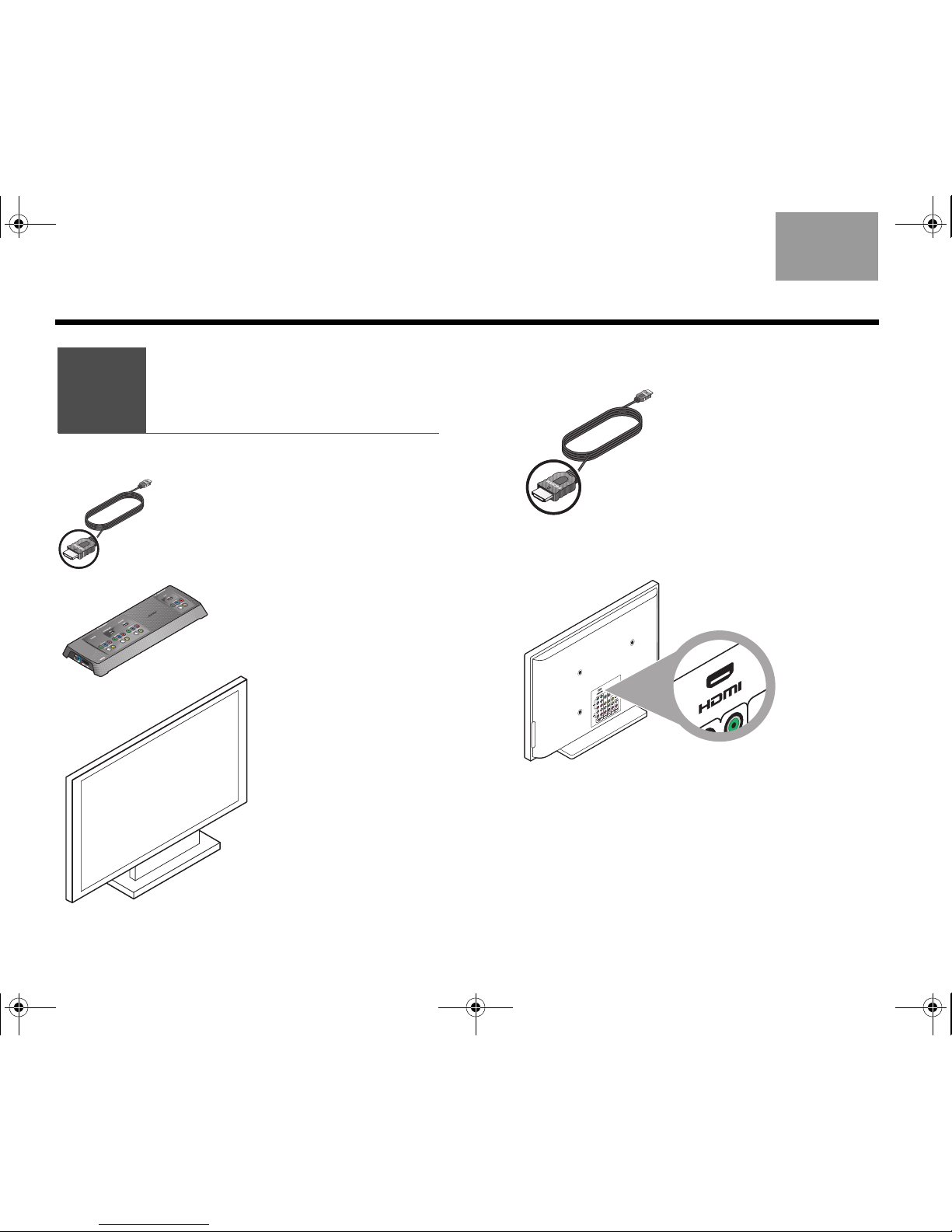
EnglishTAB 6TAB 8 TAB 7 TAB 3TAB 5 TAB 2TAB 4
1. Notice the type of plug at either end of the HDMI
cable.
2. Check to be sure your TV has an HDMI
connector that accepts this type of plug.
• If you find an HDMI connector, continue with
step 3.
• If there is no HDMI connector on your TV, skip to
“If an HDMI connection is not possible” on
page 28.
What you need to use:
VS-2 video enhancer
Your TV
HDMI cable
(provided by Bose)
Connecting
your TV
6
00.LIV_IG.book Page 26 Monday, January 12, 2009 10:58 AM
 Loading...