

Page 1

LIFESTYLE
®
28/35 DVD Home Entertainment Systems
Operating Guide
April 23, 2002
AM259776_02_V.pdf
Page 2
2
Safety Information
WARNING: To reduce the risk of fire or electric shock, do not expose the system to rain or moisture.
These CAUTION marks are located on your LIFESTYLE
®
media center and Acoustimass
®
module enclosures:
The lightning flash with arrowhead symbol, within an equilateral triangle, is intended to alert the user to the presence
of uninsulated dangerous voltage within the system enclosure that may be of sufficient magnitude to constitute a risk
of electric shock.
The exclamation point within an equilateral triangle, as marked on the system, is intended to alert the user to the presence of important operating and maintenance instructions in this owner’s guide.
CAUTION: To prevent electric shock, match wide blade of plug to wide slot, insert fully.
Class 1 laser product
The DVD player contained within the media center is classified as a CLASS 1 LASER PRODUCT
according to EN 60825-1:1994 + A11. The CLASS 1 LASER PRODUCT label is located on the bottom of the media center.
CAUTION: Use of controls or adjustments or performance of procedures other than those
specified herein may result in hazardous radiation exposure. The compact disc player should not be adjusted or
repaired by anyone except properly qualified service personnel.
Class B emissions limits
This Class B digital apparatus meets all requirements of the Canadian Interference-Causing Equipment Regulations.
Batteries
Please dispose of used batteries properly, following any local regulations. Do not incinerate.
Additional safety information
See the additional instructions on the Important Safety Instructions sheet enclosed in the shipping carton.
Please read this owner’s guide
Please take the time to follow this owner’s guide carefully. It will help you set up and operate your system properly, and enjoy all
of its advanced features. Save your owner’s guide for future reference.
CAUTION: No naked flame sources, such as lighted candles, should be placed on the apparatus.
CAUTION
CAUTION
RISK OF ELECTRICAL SHOCK
DO NOT OPEN
CAUTION: TO REDUCE THE RISK OF ELECTRIC SHOCK,
DO NOT REMOVE COVER (OR BACK).
NO USER-SERVICABLE PARTS INSIDE.
REFER SERVICING TO QUALIFIED PERSONNEL.
AVIS
RISQUE DE CHOC ÉLECTRIQUE
NE PAS OUVRIR
AFIN DE PRÉVENIR UN CHOC ÉLECTRIQUE NE PAS ENLEVER
LE COUVERCLE ARRIÈRE. IL NE SE TROUVE À L’INTÉRIEUR
AUCUNE PIÈCE POUVANT ÊTRE RÉPARÉE PAR
L’USAGER. S’ADRESSER À UN RÉPARATEUR COMPÉTENT.
CLASS 1 LASER PRODUCT
KLASSE 1 LASER PRODUKT
LUOKAN 1 LASER LAITE
KLASS 1 LASER APPARAT
©2002 Bose Corporation. No part of this work may be reproduced, modified, distributed or otherwise used without prior written permission.
Manufactured under license from Dolby Laboratories. “Dolby” and the double-D symbol are trademarks of Dolby Laboratories. Confidential
Unpublished Works. ©1992-1997 Dolby Laboratories. All rights reserved.
“DTS” and “DTS Digital Surround” are registered trademarks of Digital Theater Systems, Inc.
MPEG Layer-3 audio compression technology licensed by Fraunhofer IIS and THOMSON multimedia.
This product incorporates copyright protection technology that is protected by method claims of certain U.S. patents and other intellectual prop-
erty rights owned by Macrovision Corporation and other rights owners. Use of this copyright protection technology must be authorized by Macrovision Corporation, and is intended for home and other limited viewing uses only unless otherwise authorized by Macrovision Corporation.
Reverse engineering or disassembly is prohibited.
This product incorporates copyright protected technology and other intellectual property rights owned by Cirrus Logic, Inc. and subject to the
copyright protection of the U.S. as well as other licensing restrictions and protections. Use of this copyright protected technology is limited solely
to use with the Cirrus Logic integrated circuits incorporated in this product. Reverse engineering or disassembly is prohibited.
AM259776_02_V.pdf • April 23, 2002
Page 3

3
Where to find …
Introduction . . . . . . . . . . . . . . . . . . . . . . . . . . . . . . . . . . . . . . . . . . . . . . . . . . . . . . . . . . . . . . . . . . . . 5
Welcome . . . . . . . . . . . . . . . . . . . . . . . . . . . . . . . . . . . . . . . . . . . . . . . . . . . . . . . . . . . . . . . . . . . 5
Types of discs you can play . . . . . . . . . . . . . . . . . . . . . . . . . . . . . . . . . . . . . . . . . . . . . . . . . . . . 5
Check for region number compatibility . . . . . . . . . . . . . . . . . . . . . . . . . . . . . . . . . . . . . . . . . . . 5
Conventions used in this guide . . . . . . . . . . . . . . . . . . . . . . . . . . . . . . . . . . . . . . . . . . . . . . . . .5
Glossary . . . . . . . . . . . . . . . . . . . . . . . . . . . . . . . . . . . . . . . . . . . . . . . . . . . . . . . . . . . . . . . . . . . 5
Controls and Indicators . . . . . . . . . . . . . . . . . . . . . . . . . . . . . . . . . . . . . . . . . . . . . . . . . . . . . . . . . . 7
The remote control . . . . . . . . . . . . . . . . . . . . . . . . . . . . . . . . . . . . . . . . . . . . . . . . . . . . . . . . . . 7
Media center controls and indicators . . . . . . . . . . . . . . . . . . . . . . . . . . . . . . . . . . . . . . . . . . . . . 10
Media center display window . . . . . . . . . . . . . . . . . . . . . . . . . . . . . . . . . . . . . . . . . . . . . . . . . . .11
General System Operation . . . . . . . . . . . . . . . . . . . . . . . . . . . . . . . . . . . . . . . . . . . . . . . . . . . . . . . . 12
Turning your system on and off . . . . . . . . . . . . . . . . . . . . . . . . . . . . . . . . . . . . . . . . . . . . . . . . .12
Making sound adjustments . . . . . . . . . . . . . . . . . . . . . . . . . . . . . . . . . . . . . . . . . . . . . . . . . . . .12
Volume . . . . . . . . . . . . . . . . . . . . . . . . . . . . . . . . . . . . . . . . . . . . . . . . . . . . . . . . . . . . . . . . . 12
Changing the number of speakers playing . . . . . . . . . . . . . . . . . . . . . . . . . . . . . . . . . . . . . 12
Adjusting surround sound . . . . . . . . . . . . . . . . . . . . . . . . . . . . . . . . . . . . . . . . . . . . . . . . . . 12
Using the headphones jack . . . . . . . . . . . . . . . . . . . . . . . . . . . . . . . . . . . . . . . . . . . . . . . . . 12
System settings . . . . . . . . . . . . . . . . . . . . . . . . . . . . . . . . . . . . . . . . . . . . . . . . . . . . . . . . . . . . . 12
Using the sleep timer . . . . . . . . . . . . . . . . . . . . . . . . . . . . . . . . . . . . . . . . . . . . . . . . . . . . . . . . . 12
Changing the video output for component video connections . . . . . . . . . . . . . . . . . . . . . . . . . 12
Testing the TV on/off detector . . . . . . . . . . . . . . . . . . . . . . . . . . . . . . . . . . . . . . . . . . . . . . . . . . 13
Playing a Video DVD . . . . . . . . . . . . . . . . . . . . . . . . . . . . . . . . . . . . . . . . . . . . . . . . . . . . . . . . . . . . . 14
Before you play your first DVD . . . . . . . . . . . . . . . . . . . . . . . . . . . . . . . . . . . . . . . . . . . . . . . . . . 14
Loading and playing a DVD . . . . . . . . . . . . . . . . . . . . . . . . . . . . . . . . . . . . . . . . . . . . . . . . . . . . 14
Basic DVD operations . . . . . . . . . . . . . . . . . . . . . . . . . . . . . . . . . . . . . . . . . . . . . . . . . . . . . . . . 14
Using parental controls . . . . . . . . . . . . . . . . . . . . . . . . . . . . . . . . . . . . . . . . . . . . . . . . . . . . . . . 15
Playing an Audio CD . . . . . . . . . . . . . . . . . . . . . . . . . . . . . . . . . . . . . . . . . . . . . . . . . . . . . . . . . . . . . 16
Loading and playing a CD . . . . . . . . . . . . . . . . . . . . . . . . . . . . . . . . . . . . . . . . . . . . . . . . . . . . . 16
Basic CD operations . . . . . . . . . . . . . . . . . . . . . . . . . . . . . . . . . . . . . . . . . . . . . . . . . . . . . . . . . 16
Listening to AM/FM Radio . . . . . . . . . . . . . . . . . . . . . . . . . . . . . . . . . . . . . . . . . . . . . . . . . . . . . . . . 17
Turning the radio on . . . . . . . . . . . . . . . . . . . . . . . . . . . . . . . . . . . . . . . . . . . . . . . . . . . . . . . . . . 17
Tuning . . . . . . . . . . . . . . . . . . . . . . . . . . . . . . . . . . . . . . . . . . . . . . . . . . . . . . . . . . . . . . . . . . . . . 17
Setting a station preset . . . . . . . . . . . . . . . . . . . . . . . . . . . . . . . . . . . . . . . . . . . . . . . . . . . . . . . 17
Erasing a station preset . . . . . . . . . . . . . . . . . . . . . . . . . . . . . . . . . . . . . . . . . . . . . . . . . . . . . . . 18
Selecting a preset station . . . . . . . . . . . . . . . . . . . . . . . . . . . . . . . . . . . . . . . . . . . . . . . . . . . . . . 18
Playing External Sources . . . . . . . . . . . . . . . . . . . . . . . . . . . . . . . . . . . . . . . . . . . . . . . . . . . . . . . . . 19
Controlling external sources . . . . . . . . . . . . . . . . . . . . . . . . . . . . . . . . . . . . . . . . . . . . . . . . . . . . 19
Programming your LIFESTYLE
®
remote to control your TV . . . . . . . . . . . . . . . . . . . . . . . . . . . . 19
Programming your LIFESTYLE
®
remote to control your VCR . . . . . . . . . . . . . . . . . . . . . . . . . . 19
Programming your LIFESTYLE
®
remote to control your cable/satellite box . . . . . . . . . . . . . . . 20
Turning the system on and selecting the source . . . . . . . . . . . . . . . . . . . . . . . . . . . . . . . . . . . . 20
Changing channels using a VCR or cable/satellite box . . . . . . . . . . . . . . . . . . . . . . . . . . . . . . . 21
Recording to a tape deck . . . . . . . . . . . . . . . . . . . . . . . . . . . . . . . . . . . . . . . . . . . . . . . . . . . . . . 21
Changing System Settings . . . . . . . . . . . . . . . . . . . . . . . . . . . . . . . . . . . . . . . . . . . . . . . . . . . . . . . . 22
Using the settings menus . . . . . . . . . . . . . . . . . . . . . . . . . . . . . . . . . . . . . . . . . . . . . . . . . . . . . . 22
Changing DVD play options . . . . . . . . . . . . . . . . . . . . . . . . . . . . . . . . . . . . . . . . . . . . . . . . . . . .24
Changing CD settings . . . . . . . . . . . . . . . . . . . . . . . . . . . . . . . . . . . . . . . . . . . . . . . . . . . . . . . . 25
Changing FM settings . . . . . . . . . . . . . . . . . . . . . . . . . . . . . . . . . . . . . . . . . . . . . . . . . . . . . . . . 26
Changing AM settings . . . . . . . . . . . . . . . . . . . . . . . . . . . . . . . . . . . . . . . . . . . . . . . . . . . . . . . . 27
Changing TV/VCR/AUX/TAPE settings . . . . . . . . . . . . . . . . . . . . . . . . . . . . . . . . . . . . . . . . . . . 28
Making audio adjustments . . . . . . . . . . . . . . . . . . . . . . . . . . . . . . . . . . . . . . . . . . . . . . . . . . . . . 29
Changing the system setup . . . . . . . . . . . . . . . . . . . . . . . . . . . . . . . . . . . . . . . . . . . . . . . . . . . . 32
System setup menu . . . . . . . . . . . . . . . . . . . . . . . . . . . . . . . . . . . . . . . . . . . . . . . . . . . . . . . 33
DVD setup submenu . . . . . . . . . . . . . . . . . . . . . . . . . . . . . . . . . . . . . . . . . . . . . . . . . . . . . . 34
Parental control setup submenu . . . . . . . . . . . . . . . . . . . . . . . . . . . . . . . . . . . . . . . . . . . . . 34
Remote control setup submenu . . . . . . . . . . . . . . . . . . . . . . . . . . . . . . . . . . . . . . . . . . . . . 35
AM259776_02_V.pdf • April 23, 2002
Page 4

4
Contents
Reference . . . . . . . . . . . . . . . . . . . . . . . . . . . . . . . . . . . . . . . . . . . . . . . . . . . . . . . . . . . . . . . . . . . . . 36
Changing the house code settings . . . . . . . . . . . . . . . . . . . . . . . . . . . . . . . . . . . . . . . . . . . . . . . 36
Setting up a second listening zone . . . . . . . . . . . . . . . . . . . . . . . . . . . . . . . . . . . . . . . . . . . . . . 37
Taking care of your LIFESTYLE
®
system . . . . . . . . . . . . . . . . . . . . . . . . . . . . . . . . . . . . . . . . . . 38
Replacing the remote control batteries . . . . . . . . . . . . . . . . . . . . . . . . . . . . . . . . . . . . . . . . . . . 39
Troubleshooting . . . . . . . . . . . . . . . . . . . . . . . . . . . . . . . . . . . . . . . . . . . . . . . . . . . . . . . . . . . . . 39
Technical information . . . . . . . . . . . . . . . . . . . . . . . . . . . . . . . . . . . . . . . . . . . . . . . . . . . . . . . . . 42
Accessories . . . . . . . . . . . . . . . . . . . . . . . . . . . . . . . . . . . . . . . . . . . . . . . . . . . . . . . . . . . . . . . . 43
Warranty . . . . . . . . . . . . . . . . . . . . . . . . . . . . . . . . . . . . . . . . . . . . . . . . . . . . . . . . . . . . . . . . . . . 43
Contacting customer service . . . . . . . . . . . . . . . . . . . . . . . . . . . . . . . . . . . . . . . . . . . . . . . . . . .43
AM259776_02_V.pdf • April 23, 2002
Page 5
5
Introduction
Welcome
Thank you for purchasing a LIFESTYLE
®
DVD-based home entertainment system. Through
proprietary Bose technologies and innovative LIFESTYLE
®
systems design, it delivers superior performance for both music and video programming from an elegant and easy-to-use
system.
Note: Because DVD is a relatively new technology, please take the time to read through this
manual and familiarize yourself with the features of your new system.
Types of discs you can play
The DVD player in your system can play the following types of discs having the
corresponding logos:
• Video DVDs
• Audio CDs
• CD-Rs or CD-R/Ws
• MP3 CDs
Check for region number compatibility
For a DVD player and DVD disc to be compatible, their region numbers must match. These
numbers are allocated according to where the player and disc are sold.
Check the region number on the bottom of the media center included with your system. Then
be sure to choose only DVD discs that show the same region number on the disc label or
packaging.
For example, a Region 1 DVD player should display the following mark:
Conventions used in this guide
Operating instructions include names of buttons on the remote control and on the media center front panel, and menu items appearing on your TV screen and on the media center display.
• Button names appear in boldface type. For example, “Press the CD/DVD button”.
If a button has only a symbol, that will be used.
• On-screen display messages appearing on your TV screen will be in boldface type with a
line above and below. For example, “Use the Audio Setup menu to adjust the sound”.
• Messages appearing on the media center display are represented by a narrow boldface
uppercase type. For example, “ REPEAT: TRACK appears when the repeat disc track mode is
selected”.
Glossary
Aspect ratio – The shape of the rectangular picture in a TV set expressed as the width of the
picture relative to the height. For example, if a TV picture has an aspect ratio of 4:3 (r ead as 4
by 3), the shape of that picture is 4 units wide by 3 units high. The two standard TV aspect
ratios are 4:3 and 16:9.
Chapter – In DVD-Video, a division of a title. Technically called a part of title (PTT).
AM259776_02_V.pdf • April 23, 2002
Page 6

6
Introduction
Component video – A video system containing three separate color component signals,
either red/green/blue (RGB) or chroma/color dif ference (YPbPr), in analog or digital form. The
MPEG-2 encoding system used by DVD is based on color-difference component digital
video.
Composite video – A single video signal that contains luminance, color, and synchronization
information. NTSC and PAL are examples of composite video systems.
1
– The logo representing Dolby Digital.
Dolby Digital – A perceptual coding system for audio, developed by Dolby Laboratories and
accepted as an international standard. Dolby Digital is the most common means of encoding
multi-channel audio.
– The logo representing DTS.
DTS – A type of multi-channel surround sound format used on discs.
DVD – An acronym that is most commonly known to mean Digital Video Disc or Digital Versa-
tile Disc. The audio/video/data storage system is based on 12-cm optical discs.
DVD video – A standard for storing and reproducing audio and video on DVD-ROM discs,
based on MPEG video, Dolby Digital and MPEG audio, and other proprietary data formats.
IR
– An acronym for infrared. Pertains to the type of remote that sends/receives commands
on an infrared light beam.
Letterbox – A video format which has black borders at the top and bottom of the picture.
MP3 – MPEG-1 Layer III audio. This is a compressed audio format that allows you to record
many hours of music on a single CD.
NTSC – An acronym for National Television System Committee. The U.S. organization that
developed both the American Black & White and Color television systems.
PAL – An acronym for Phase Alternate Line. This is one of several composite video systems.
The PAL format is used extensively in Western Europe.
PCM – The form of the digital audio signal used for both CD and laserdisc. It is a serial data
stream that is coded for transmission or recording.
S-video – A video interface standard that carries separate luminance and chrominance sig-
nals, usually on a four-pin mini-DIN connector. Also called Y/C. The quality of S-video is significantly better than composite video since it does not require a comb filter to separate the
signals. Most high-end televisions have S-video inputs.
Videostage
®
5 decoding circuitry – Proprietary Bose invention which gives you a five-chan-
nel surround sound experience from everything you listen to – VHS tapes, stereo CDs, even
mono TV programs.
YPbPr – A component analog video signal containing one luminance and two chrominance
components. Often referred to loosely as YUV or Y, B-Y, R-Y.
AM259776_02_V.pdf • April 23, 2002
Page 7
7
Controls and Indicators
The remote control
The advanced radio-frequency remote control works fr om anywhere within most homes. Simply press the desired button. You do not need to aim the remote at the media center.
Note: Some types of buildings create “dead spots” where the remote will not operate. Move
the remote a foot or two and try again. You can also move the media center a few feet to a
location with better remote response, or extend the media center’ s power cor d which contains
the antenna for the remote control.
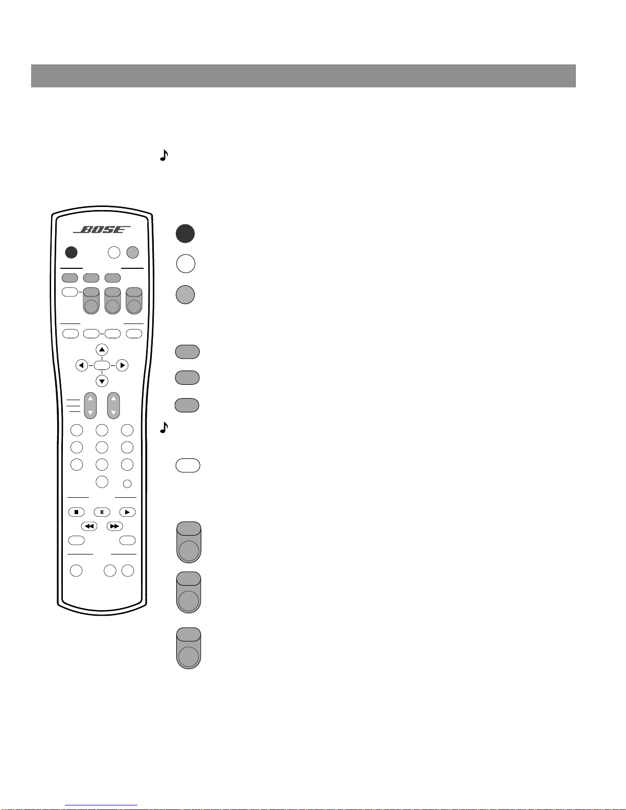
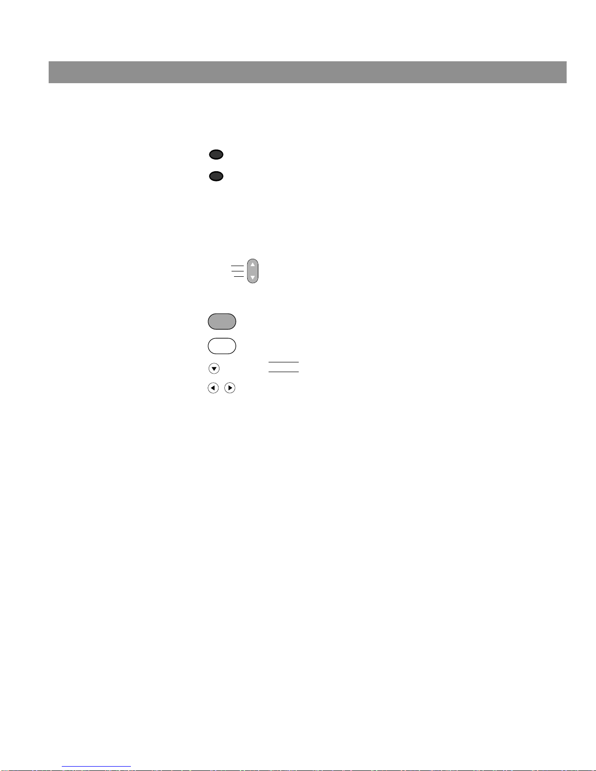
Power on/off and mute controls
Source/input controls
Note: Y our LIFESTYLE
®
remote can be used to control your TV, VCR, or AUX device only after
it is programmed with the correct device code. See “Playing External Sources” on page 19.
AUDIO
SurroundSpeakers
SOURCE / INPUT
MENU / NAVIGATION
Seek
Volume
PLAYBACK
Pause PlayStop
Channel
Chapter
Preset
Track
Previous
Tune
Guide Exit
PowerPowerPower
TV Input
DVD
Menu
Repeat
FM/AM
Tape
2-3-5
+
-
Mute
Mute
All
Enter
1203
456
789
Shuffle
Settings
CD/DVD
AUXVCRTV
On
Off
Turns the system on and off.
Mutes the volume for all connected speakers (all zones and rooms).
Mutes/unmutes the volume in the current zone.
Selects the built-in CD/DVD player and turns the system on.
Selects the built-in FM/AM tuner and turns the system on to the previously-selected
station. Switches between FM and AM when the tuner is on.
Selects the Tape source and turns the system on.
Changes the external input to your TV. For example, your TV might have two external inputs, one of which you connect to your cable box and the other to a VCR. This
button will allow you to alternately switch between these two inputs.
To use this function, (1) your TV’s remote control must have a similar control button,
and (2) your LIFESTYLE
®
remote control must be programmed to control your TV.
TV
- The top of this button turns your system on and selects your TV (if properly
connected) as the sound source.
Power – The bottom of this button turns your TV on and off.
VCR – The top of this button turns your system on and selects your VCR as the
sound source.
Power – The bottom of this button turns your VCR on and off.
AUX – The top of this button turns your system on and selects the AUX input (such
as cable box or satellite receiver) as the sound source.
Power – The bottom of this button turns your AUX device on and off.
On
Off
Mute
All
Mute
CD/DVD
FM/AM
Tape
TV Input
Power
TV
Power
VCR
Power
AUX
AM259776_02_V.pdf • April 23, 2002
Page 8
8
Controls and Indicators
The remote control – continued
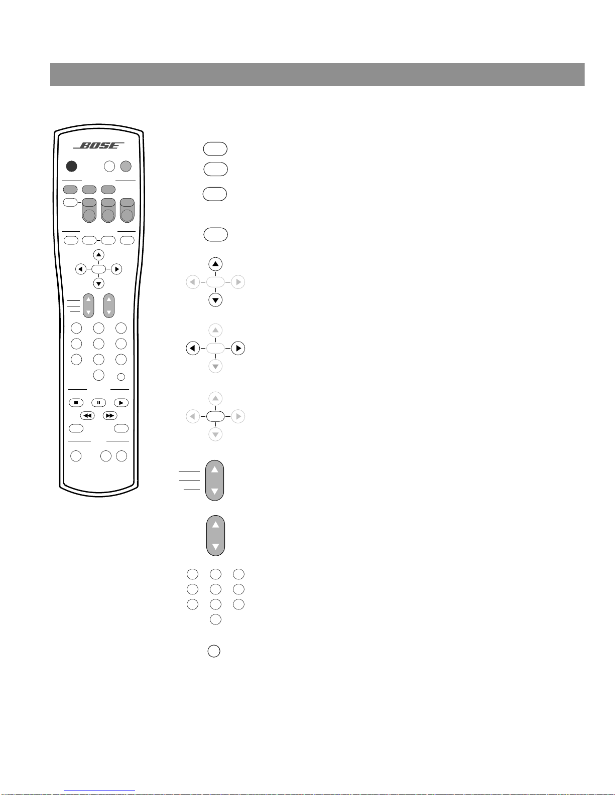
System menu/navigation controls
Displays or exits the menu of the DVD disc that is currently loaded.
Displays the electronic program guide of TV listings.
Steps you back to a previous level in the settings menu for the current
source.
Exits the electronic program guide of TV listings.
Displays or exits the settings menu for the current source.
Tunes the FM/AM radio up/down to the next higher/lower frequency.
Selects the next item, up or down, in the settings menu.
Seeks backward/forward to the next strong radio station.
Changes the setting of a menu item.
Enters submenus or submits settings, choices or entries to
the system.
Skips to the next/previous TV channel, DVD chapter, radio station preset, or CD track.
Raises ▲ or lowers ▼ the volume of the current source. If the system
is muted, pressing ▲ unmutes the current source in the current zone.
Pressing ▼ lowers the volume setting without unmuting the current
source.
The numeric keypad allows you to access a DVD chapter, CD track,
TV channel, or a radio station preset by directly entering the desired
number. It also allows you to directly enter some system settings.
Skips to the previous TV channel (if your TV supports this feature).
AUDIO
SurroundSpeakers
SOURCE / INPUT
MENU / NAVIGATION
Seek
Volume
PLAYBACK
Pause PlayStop
Channel
Chapter
Preset
Track
Previous
Tune
Guide Exit
PowerPowerPower
TV Input
DVD
Menu
Repeat
FM/AM
Tape
2-3-5
+
-
Mute
Mute
All
Enter
1203
456
789
Shuffle
Settings
CD/DVD
AUXVCRTV
On
Off
DVD
Menu
Guide
Exit
Settings
Seek
Tune
Enter
Seek
Tune
Enter
Seek
Tune
Enter
Channel
Chapter
Preset
Track
Volume
1203
456
789
Previous
AM259776_02_V.pdf • April 23, 2002
Page 9
9
Controls and Indicators
The remote control – continued
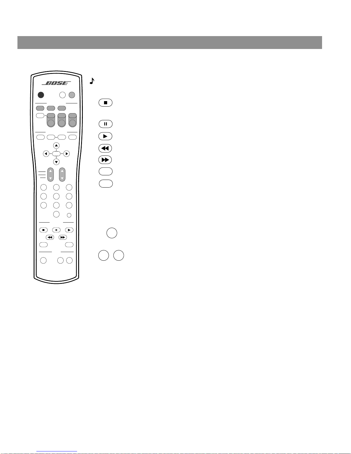
Playback controls
Note: All playback controls, except Shuffle and Repeat , can also be used to control your
VCR. See “Programming your LIFESTYLE® remote to control your VCR” on page 19.
Audio controls
Stops the disc player. For DVDs only , the system remembers the point where
the disc was stopped. Pressing Stop ■ a second time returns to the beginning
of the disc.
Pauses the disc player.
Starts the disc player.
By pressing and holding, scans backward through the disc currently playing.
By pressing and holding, scans forward through the disc currently playing.
Plays CD tracks in random order. Press Shuffle again to cancel this mode.
Repeats a CD, CD track, DVD chapter, or DVD title. Press Repeat again to
change the repeat mode.
Pressing this button repeatedly changes the number of speakers playing
to 2, 3, or 5 speakers.
In surround (5-speaker) mode, raises (+) or lowers (–) volume of the surround
speakers.
AUDIO
SurroundSpeakers
SOURCE / INPUT
MENU / NAVIGATION
Seek
Volume
PLAYBACK
Pause PlayStop
Channel
Chapter
Preset
Track
Previous
Tune
Guide Exit
PowerPowerPower
TV Input
DVD
Menu
Repeat
FM/AM
Tape
2-3-5
+
-
Mute
Mute
All
Enter
1203
456
789
Shuffle
Settings
CD/DVD
AUXVCRTV
On
Off
Shuffle
Repeat
Speakers
2-3-5
Surround
+
-
AM259776_02_V.pdf • April 23, 2002
Page 10
10
Controls and Indicators
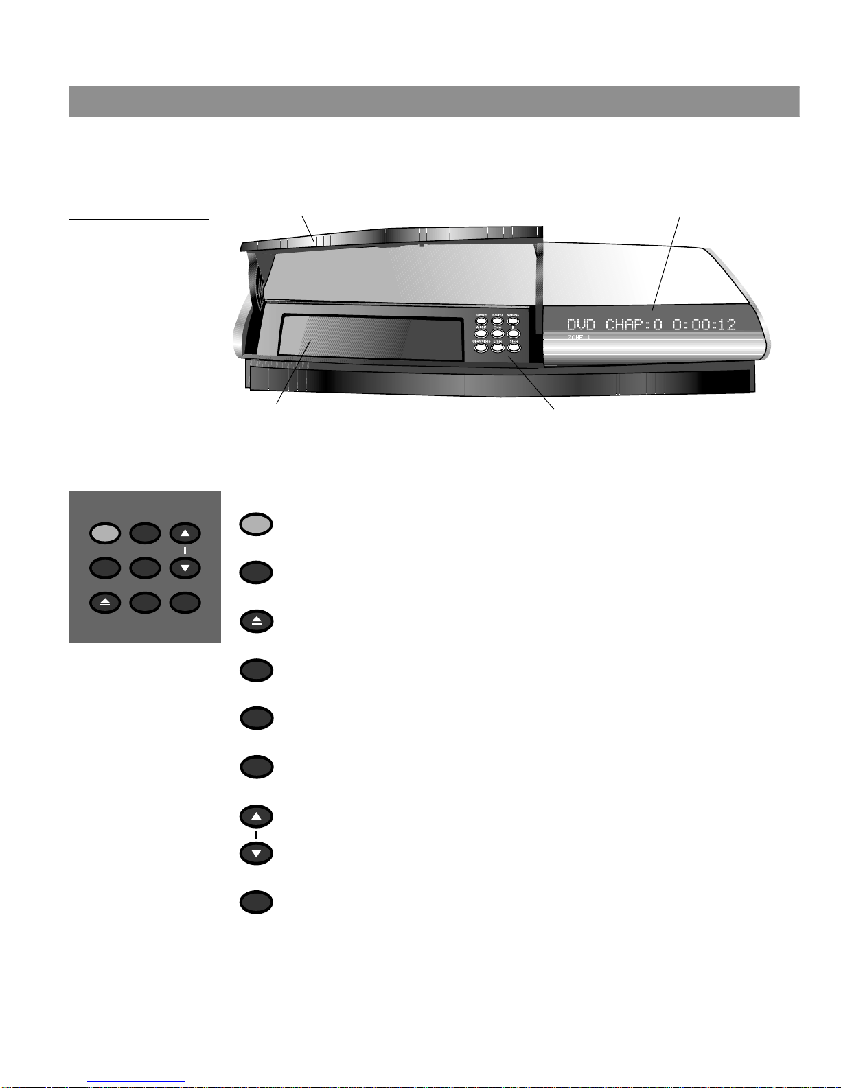
Media center controls and indicators
The media center has a control panel and CD tray located under its front panel door. The
information display window fills the right half of the front (Figure 1).
Figure 1
Media center front
Media center control buttons
The media center has nine control buttons located under its front panel door.
Front panel door - lift up to open
Control button panel
Display window
DVD/CD tray
On/Off Source Volume
Enter
Erase
Store
All Off
Open/Close
Turns the system on or off in zone 1.
Turns off the system and all connected speakers (all zones and rooms).
Opens/closes the disc tray.
Steps through the available source selections.
Confirms storage of presets.
Removes a radio station preset.
Removes custom equalization settings.
Pressing ▲ raises the volume of the system and unmutes the current
source, if muted. Pressing ▼ lowers the volume of the system; if the
current source is muted, it stays muted.
Stores a radio station preset.
On/Off
All Off
Open/Close
Source
Enter
Erase
Volume
Store
AM259776_02_V.pdf • April 23, 2002
Page 11
11
Controls and Indicators
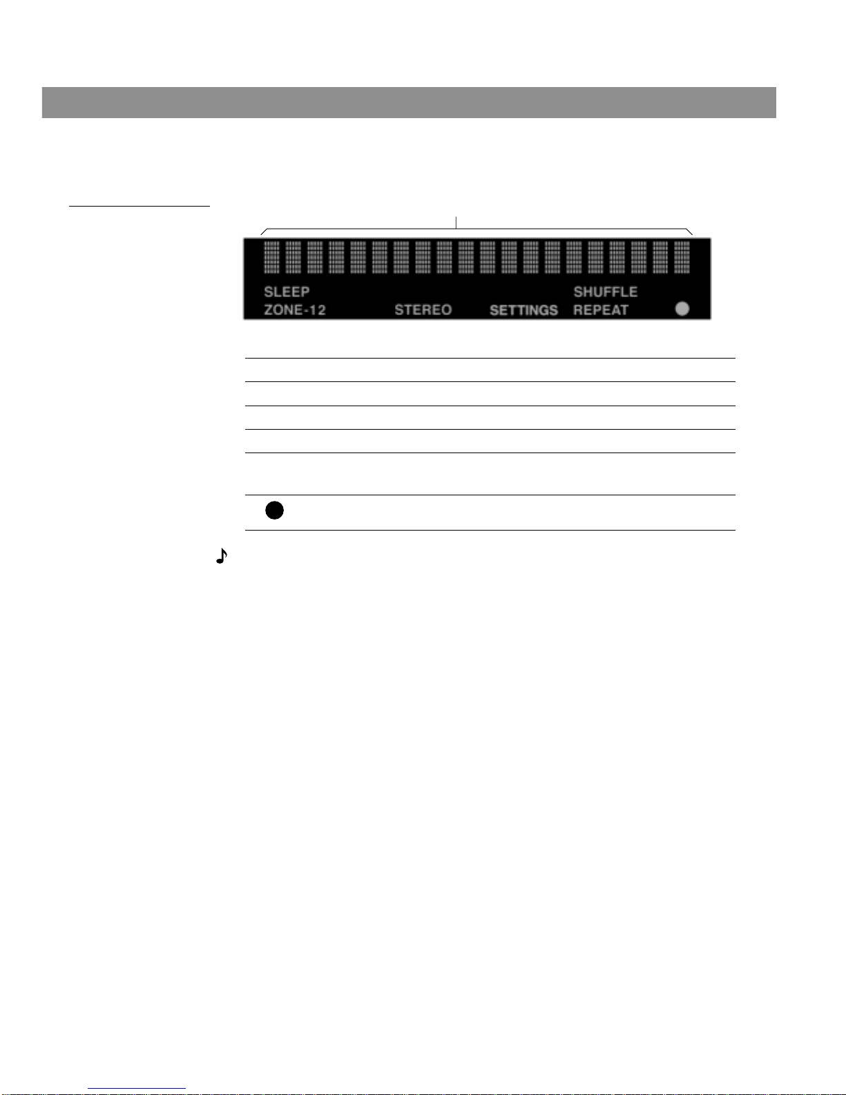
Media center display window
The media center display window shows you information about your system (Figure 2).
Figure 2
Elements of the media
center display
Note: When you make changes using the on-screen display on your TV, the changes may not
appear simultaneously on the media center’s display.
SLEEP
Lights up when the system sleep timer is on.
ZONE-1 2
Lights up with either the 1 or the 2 to indicate the current zone.
STEREO
Lights up to indicate that FM stereo is being received.
SETTINGS
Lights up when settings menu information is being displayed.
SHUFFLE
REPEAT
The appropriate icon lights up to indicate the current CD mode,
SHUFFLE or REPEAT.
Lights up briefly whenever a remote control command is received by the
media center.
Twenty characters display system messages and source-related information.
AM259776_02_V.pdf • April 23, 2002
Page 12

12
General System Operation
Turning your system on and off
You can turn your system on and off using the On/Off button on the remote control or the
media center button panel. When you turn it on with either On/Off button, the source that
was played last is automatically selected. You can also press any source button on the
remote to turn the system on and select the source at the same time.
Making sound adjustments
Volume
System volume can be raised or lowered using the Volume ▲ ▼ buttons on the remote or the
media center button panel.
Changing the number of speakers playing
When you turn on a source, the number of speakers used for that source is automatically
determined. For example, when you select FM, the front right and left speakers are used.
When you play a DVD video, all five speakers are turned on. You can change the number of
speakers used for any source by pressing the Speakers 2-3-5 button on the remote control.
Adjusting surround sound
The sound level of the surround (rear) speakers in your system can be adjusted in small steps
using the Surround + / – buttons on your remote. In surround (5-speaker) mode, Surround+
raises the volume; Surround– lowers it.
Using the headphones jack
For private listening, you can connect a headset to the headset jack located on the right side
of the media center. When a headset is connected, all ZONE 1 speakers are muted.
System settings
When necessary , the system settings can be changed using the system settings menus. See
“Changing System Settings” on page 22.
Using the sleep timer
Your system includes a sleep timer, which can be set to turn your system off automatically
after 10 to 90 minutes of listening to any source. This timer can be accessed through the settings menu. See “Using the settings menus” on page 22.
Changing the video output for component video connections
If your TV or video monitor is capable of component video input signals, and you have connected your TV to your system using the component video adapter (included), you must
change the video output setting in the settings menu to “YPbPr”. This will enable the media
center to send the correct video signals to your TV.
To change the video output setting, see “Using the settings menus” on page 22, and
“Changing the system setup” on page 32.
AM259776_02_V.pdf • April 23, 2002
Page 13
13
General System Operation
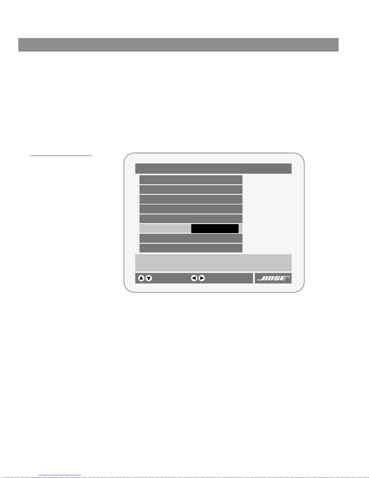
Testing the TV on/off detector
The TV on/off detector causes your media center to turn your TV on and off automatically
when you select a video source on your LIFESTYLE® remote. To make sure the detector is
mounted in the proper position on the back of your TV, follow these steps:
1. Turn your TV on.
2. Press the TV button on the LIFESTYLE
®
remote.
3. Press the Settings button and scroll down to the TV Status display.
If the display (Figure 3) indicates, Detected TV Power: On, the TV on/off detector
is working properly.
If the display indicates, Detected TV Power: Off, move the detector
around until you find a position that changes this status to On.
4. After you find the proper position for the detector, use the mounting strip and attach the
detector to the back of your TV in that position. See “Installing the TV on/off detector” in
your LIFESTYLE® Installation Guide.
Figure 3
TV Status Display
Settings (TV)
Audio Setup
TV Analog Input: 0
TV Digital Input: 0
Displays information about the current source.
selects item
Sleep Timer: Off
changes setting
TV Status:
System Setup
TV
Audio Input: Analog
Code: 0036
Detected TV Power: On
Enter
Enter
This line indicates the
proper operation of
the TV on/off detector.
AM259776_02_V.pdf • April 23, 2002
Page 14
14
Playing a Video DVD
Before you play your first DVD
This section tells you how to use the DVD player in your system to play video DVDs. Before
you play your first DVD, make note of the following:
• Make sure that you are familiar with the functions of the remote control buttons (see “The
remote control” on page 7). Although some remote contr ol buttons look the same as those
found on a VCR or CD player remote, their functions are different.
• In order for some system features to work, the DVDs that you play must be encoded with
the information for that feature. For example, in order to display subtitles while watching a
movie, the disc must contain subtitle information.
• Both the DVD player in your system and the discs you play are coded by region. In order for
a disc to play, these region codes must match. Check the label on the media center or on
the shipping carton for your player’s region code.
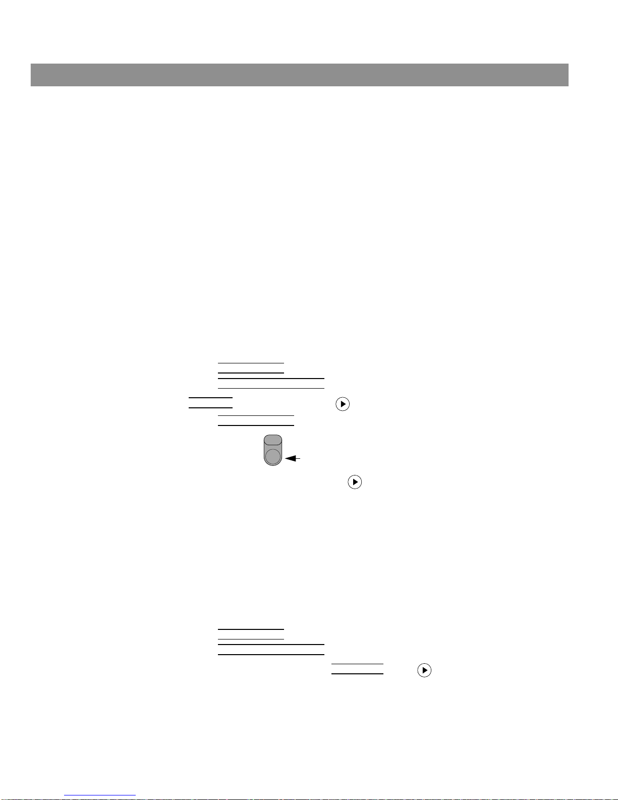
Loading and playing a DVD
1. Turn your television on.
2. Press to select the DVD player. If the system is off, this will also turn it on.
3. Lift up the media center front door and press .
4. Insert the DVD disc into the tray (label side up).
5. Press to close the disc tray.
If the DVD disc does not start to play automatically, press . Some DVD videos will
ask you to make some on-screen selections before the movie starts to play.
Note: Your system was set at the factory to automatically play a disc when it is loaded. This
feature can be turned off in the system settings menu. See “DVD setup submenu” on
page 34.
Basic DVD operations
CD/DVD
Open/Close
Open/Close
If you want to: Do this:
Pause a DVD movie … Press .
Resume play … Press or .
Stop a DVD movie … Press once. Pressing continues the movie
from the point you stopped the movie.
Press twice. Pressing starts the movie from
the beginning.
Skip to the next chapter … Press Chapter up.
Channel
Chapter
Preset
Track
AM259776_02_V.pdf • April 23, 2002
Page 15
15
Playing a Video DVD
Basic DVD operations – cont.
Using parental controls
Playback restrictions can be placed on your DVD player by choosing a level of parental control and setting up a system password using the settings menu. See “Parental control setup
submenu” on page 34. For information on using the system settings menu, see “Changing
System Settings” on page 22.
The Motion Picture Association of America (MPAA) standard movie ratings are mapped to
specific parental levels of control in the following table. There are eight levels, each less
restrictive of content than the level below. The DVD player in your new LIFESTYLE® home
entertainment system can be set to any of these eight levels.
The password you created will prevent unauthorized viewing of DVD videos having a rating
higher than the parental control setting. When you load a DVD video into a system having a
parental control setting of 4, for example, only DVD videos that have a MPAA rating of 4 (PG-
13) and lower can be played without entering a password.
The password also prevents others from changing the parental control setting without per-
mission.
If you want to: Do this:
Skip to the previous chapter … Press Chapter down twice.
Repeat a chapter … While playing the chapter you want to repeat, press .
Search backward or forward … Press and hold or .
Channel
Chapter
Preset
Track
Repeat
MPAA
Rating
Parental
Control
Setting
Audience Restriction
8 None
NC-17 7 Adult audiences
R 6 Mature audiences
5 Mature teenage audiences
PG-13 4 Teenage audiences
PG 3 Mature young audiences
2 Most audiences
G 1 General
AM259776_02_V.pdf • April 23, 2002
Page 16
16
Playing an Audio CD
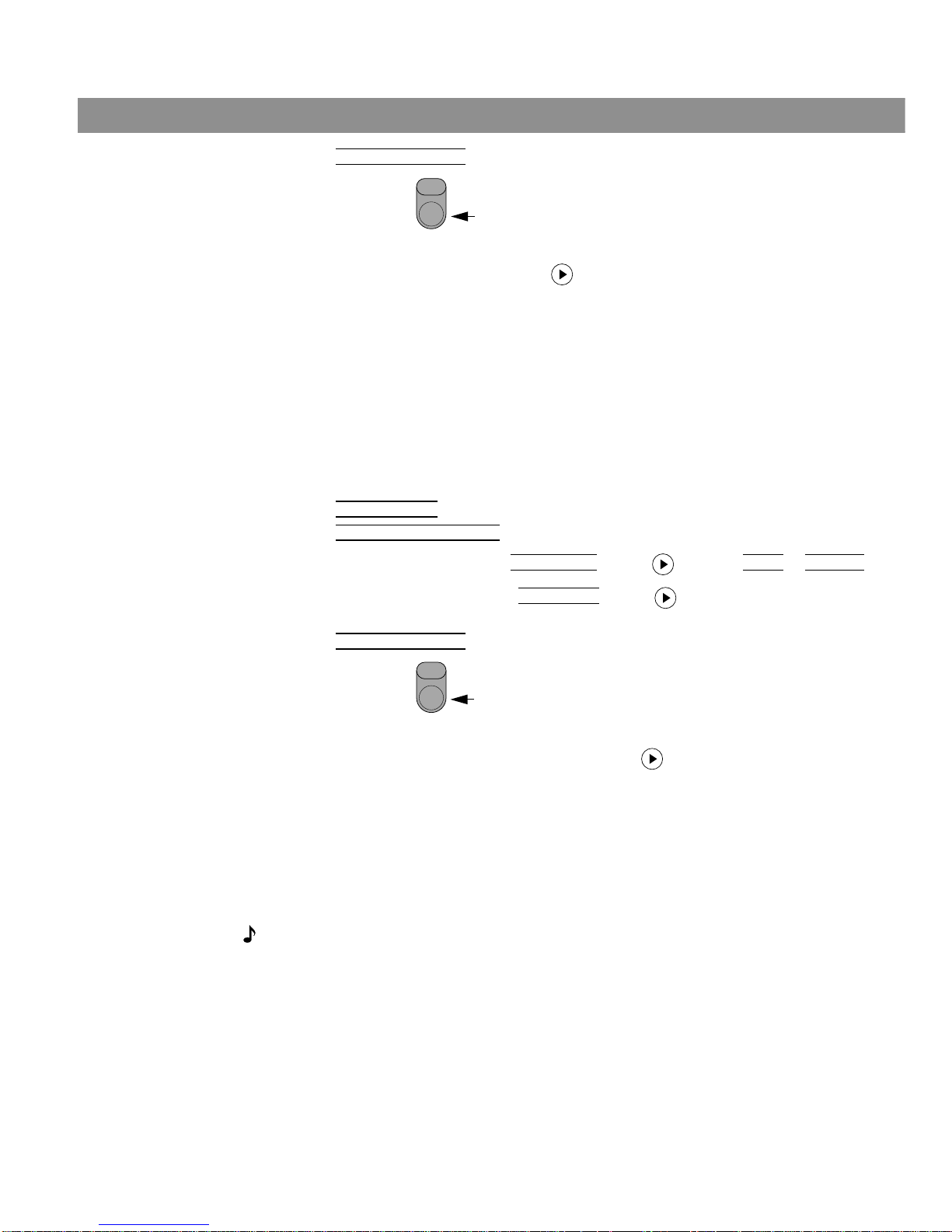
Loading and playing a CD
Your system can play regular audio CDs and MP3 CDs. While playing a CD, the media center
display window will show you the track number, track time, and repeat or shuffle mode.
1. Press to select the CD player. If the system is off, this will also turn it on.
2. Lift up the media center front door and press .
3. Insert the audio CD into the tray.
4. Press to close the disc tray.
If the CD does not start to play automatically, press Play .
Basic CD operations
CD/DVD
Open/Close
Open/Close
If you want to: Do this:
Pause a CD … Press .
Resume play of paused CD … Press again or .
Stop a CD … Press .
Go to next track … Press Track up.
Go to beginning of current track … After track has played for several
seconds, press Track down.
Go to a previous track … If track has played for several
seconds, press Track down
twice.
If not, press once.
Scan a CD backward/forward … Press and hold scan backward or forward .
Note: The scan feature is not available for MP3 CDs.
Randomly play CD tracks … Press after loading CD.
Cancel random play … Press while in Shuffle mode.
Repeat a track Press after loading a CD.
Repeat a CD Press twice after loading a CD.
Channel
Chapter
Preset
Track
Channel
Chapter
Preset
Track
Channel
Chapter
Preset
Track
Shuffle
Shuffle
Repeat
Repeat
AM259776_02_V.pdf • April 23, 2002
Page 17
17
Listening to AM/FM Radio
Turning the radio on
Press on the remote to select the radio tuner. If the system is off, this will also turn it on.
When it turns on, the radio will be playing the most recently selected FM or AM station.
Tuning
You can tune to a radio station in the following ways:
Setting a station preset
Your LIFESTYLE® media center can store up to 25 AM and 25 FM stations.
1. Lift up the media center door.
2. Using the remote, tune to a radio station you want to store as a preset.
3. Press on the media center. The display shows, STORE TO PRESET <number>?,
where <number> is the next lowest available preset number. If you do not want to store to
this preset number, press Preset up or down to change the preset number.
4. Press again or press to save the preset. The display shows,
STATION SAVED to <number>.
Note: If you attempt to store mor e than 25 AM or 25 FM stations, the media center will display
the message,
ALL PRESETS FULL … … ERASE A PRESET
Note: To change an existing preset, first you must erase the preset station and then store a
new station to that preset number.
FM/AM
If you want to: Do this:
Switch between FM and AM … Press on the remote.
Seek the next strong station … Press Seek or on the remote.
Manually tune to a station … Press Tune or on the remote.
Select a preset station … Press Preset .
or
Key in a preset number on the keypad and press .
FM/AM
Channel
Chapter
Preset
Track
Enter
Store
Channel
Chapter
Preset
Track
Store
Enter
AM259776_02_V.pdf • April 23, 2002
Page 18
18
Listening to AM/FM Radio
Erasing a station preset
1. Lift up the media center door.
2. Using the remote, select the preset you want to erase.
3. Press on the media center. The display shows, ERASE PRESET <number>?
4. Press again to delete the preset. The display shows, PRESET <number> ERASED.
Selecting a preset station
You can select preset stations using the remote control or the on-screen settings menu.
To select a preset with the remote control:
• Key-in the preset number on the numerical keypad, or
• Press Preset up or down to change the preset number
To select a preset using the settings menu:
1. Press on the remote and select the FM or AM source.
2. Press . (Make sure your TV is on.)
3. Press and select Pr
eset.
4. Press / to step through the preset stations.
Erase
Erase
Channel
Chapter
Preset
Track
FM/AM
Settings
AM259776_02_V.pdf • April 23, 2002
Page 19
19
Playing External Sources
Controlling external sources
Follow the instructions in your LIFESTYLE® system Installation Guide for connecting an external component. Turn on your component directly or by using its remote control. If you like,
you can program your new LIFESTYLE
®
remote to control your external component. The LIF-
ESTYLE
®
remote can be programmed for most brands of TVs, VCRs, and cable/satellite con-
trol boxes.
Your media center has an infrared (IR) emitter behind the media center display to communi-
cate with components your remote is programmed to control. However, a component may be
positioned where it cannot receive the IR signals emitted from the fr ont of the media center. If
you experience difficulty operating one of your components, you can install the optional IR
emitter cable included with your system. See “Connecting the optional IR emitter cable” in
your LIFESTYLE® Installation Guide.
Programming your LIFESTYLE® remote to control your TV
If you want to control your TV with your LIFESTYLE® remote control, you can program it to
operate your brand of TV using the system settings menu. See the “Remote control setup
submenu” on page 35.
1. Turn on your TV.
2. Press the TV button on the LIFESTYLE
®
remote control.
3. Press the Settings button.
4. Select System Setup and press Enter.
5. Select Remote Control Setup and press Enter.
6. TV Brand
is selected first. Press until your TV brand name is shown.
7. Select TV Device Code
. The first 4-digit device code is shown.
8. Press TV Power on the LIFESTYLE
®
remote control to see if the TV turns off.
9. If you cannot turn off your TV, press to choose the next device code, and press the
TV Power button again. Test each device code until you find one that turns your TV off
and on again when pressing the TV Power button.
Programming your LIFESTYLE® remote to control your VCR
If you want to control your VCR with your LIFESTYLE® remote control, you can program it to
operate your brand of VCR using the system settings menu. See the “Remote control setup
submenu” on page 35.
1. Turn on your TV and VCR.
2. Press the VCR button on the LIFESTYLE
®
remote control.
3. Press the Settings button.
4. Select System Setup
and press Enter.
5. Select Remote Contr
ol Setup and press Enter.
6. Scroll down the menu and select VCR Brand
. Press until your VCR brand name is
shown.
Power
TV
AM259776_02_V.pdf • April 23, 2002
Page 20
20
Playing External Sources
7. Select VCR Device Code. The first 4-digit device code is shown.
8. Press VCR Power on the LIFESTYLE
®
remote control to see if the VCR turns
off.
9. If you cannot turn off your VCR, press to choose the next device code, and press
the VCR Power button again. Test each device code until you find one that turns your
VCR off and on again when pressing the VCR Power button.
Programming your LIFESTYLE® remote to control your cable/satellite box
If you want to control your cable/satellite box (connected to the AUX input) with your LIFESTYLE
®
remote control, you can program it to operate your brand of cable/satellite box using
the system settings menu. See the “Remote control setup submenu” on page 35.
1. Turn on your TV and cable/satellite box.
2. Press the AUX button on the LIFESTYLE® remote control.
3. Press the Settings button.
4. Select System Setup
and press Enter.
5. Select Remote Control Setup and press Enter.
6. Scroll down the menu and select AUX Device
. Press to select cable or satellite.
7. Scroll down once more and select AUX Brand. Press until your cable/satellite box
brand name is shown.
8. Select AUX Device Code
. The first 4-digit device code is shown.
9. Press AUX Power on the LIFESTYLE
®
remote control to see if the cable/satel-
lite box turns off.
10. If you cannot turn off your cable/satellite box, press to choose the next device
code, and press the AUX Power button again. Test each device code until you find one
that turns your cable/satellite box off and on again when pressing the AUX Power button.
Turning the system on and selecting the source
Press the Tape (tape), VCR, or AUX button on the remote or press Source on the media cen-
ter until the desired component is selected. This turns your system on and selects the component connected to that input. If the system is already on, this button selects the
component.
Note: Selecting an external source turns the system on in surround (5-speaker) mode.
Press the Speakers 2-3-5 button to change the number of speakers playing.
Power
VCR
Power
AUX
AM259776_02_V.pdf • April 23, 2002
Page 21

21
Playing External Sources
Changing channels using a VCR or cable/satellite box
You may want to change TV channels using a VCR or a cable/satellite box instead of using
the tuner in your TV. To do this you will need to change the TV tuner selection in the system
settings menu:
1. Turn on your TV.
2. Press the TV button on the LIFESTYLE® remote control.
3. Press the Settings button.
4. Select System Setup
and press Enter.
5. Select Remote Control Setup and press Enter.
6. Select TV T
uner.
7. Change the setting to VCR or AUX.
8. Press the Settings button again.
9. Use the selected tuner to switch TV channels.
Recording to a tape deck
To record to a connected tape deck:
1. Choose the source (FM/AM, DVD/CD, or AUX) you want to record.
2. Set the tape deck to record.
3. Play the source. In a two-zone system, be sure to play the source in zone 1.
AM259776_02_V.pdf • April 23, 2002
Page 22
22
Changing System Settings
Using the settings menus
To display the settings menu on your TV screen:
Press the Settings button. The displayed menu will contain items related to the currently
selected source. For example, if you press the Settings button while watching a DVD, you will
see a menu similar to the one in Figure 4. This menu is generated by your LIFESTYLE
®
system
and not by the currently loaded DVD.
Note: When you make changes using the on-screen display on your TV, the changes may not
appear simultaneously on the media center’s display.
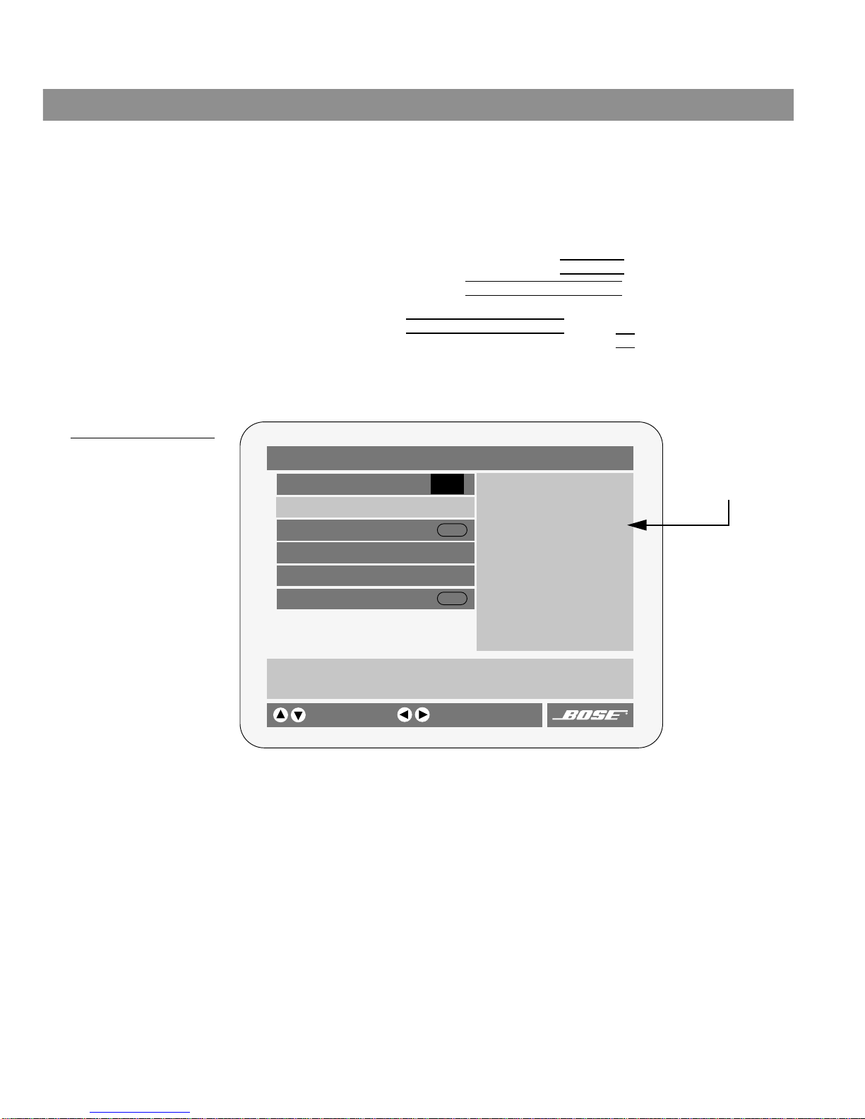
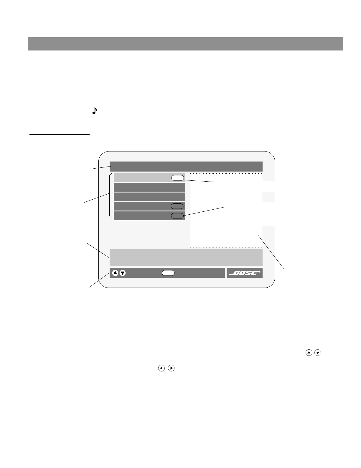
Figure 4
Elements of the on-screen
menu displays
To navigate around in the settings menu:
Use the MENU/NAVIGATION buttons on your remote to move within the on-screen menus.
Figure 4 shows you the elements of the on-screen menu displays.
To select a menu item and change the setting:
Selected items are highlighted with a lighter color . Use the up/down arr ow buttons ( ) to
scroll up or down the list and select the item you want. To change the setting, use the right
and left arrow buttons ( ).
Settings (DVD)
DVD Play Options
Sleep Timer: Off
DVD Status:
Audio Setup
System Setup
Lists options for how to play and view the current DVD.
selects item
Title bar – shows the
name of the current menu
(the currently selected
source is in parentheses).
Menu items – a list of
choices is shown in
this space.
Menu item description –
Describes the selected
menu item.
Navigation controls – Identifies which remote
control buttons to use within this menu.
Status display area –
this area is used to
display status information when a status
item is selected.
Enter
Enter
Enter
Enter
goes to submenu
Submenu – This symbol indicates that there
is a submenu of items for this selection.
Press the Enter button on the remote to go to
this submenu.
Selected menu item – menu items are selected
(highlighted) with the up/down arrow keys.
AM259776_02_V.pdf • April 23, 2002
Page 23
23
Changing System Settings
To enter a submenu:
When you see the Enter button symbol to the right of the selected item, that item has a submenu of additional items. With the item selected, press Enter to go to the submenu.
To exit a submenu
Pressing the Exit button on the remote steps back one level in the menu structure.
To exit the settings menu and clear it from your TV screen:
Press the Settings button again.
To change a setting
Select the item you want to change using the up/down arrow buttons. Press the left or right
arrow button to choose the desired setting. Select another item to change or press the Set-
tings button to leave the settings menu.
Figure 5
Example of a settings menu
on-screen display
To view the system status
The settings menu provides a selection for displaying the status of the currently selected
source. Press the Settings button to step down to the status selection. The system status is
shown on the right-hand side of the menu display (see Figure 4).
DVD Play Options (1 of 2)
Title: 1 of 3
Chapter: 23 of 30
Title Time: 2:23:02
Time Display: Elapsed
Motion Control: Play 1x
Chooses an audio track for the current DVD.
selects item
Camera Angle: 1 of 1
More…
Audio Track: English 2222 D 5.1
changes setting
AM259776_02_V.pdf • April 23, 2002
Page 24
24
Changing System Settings
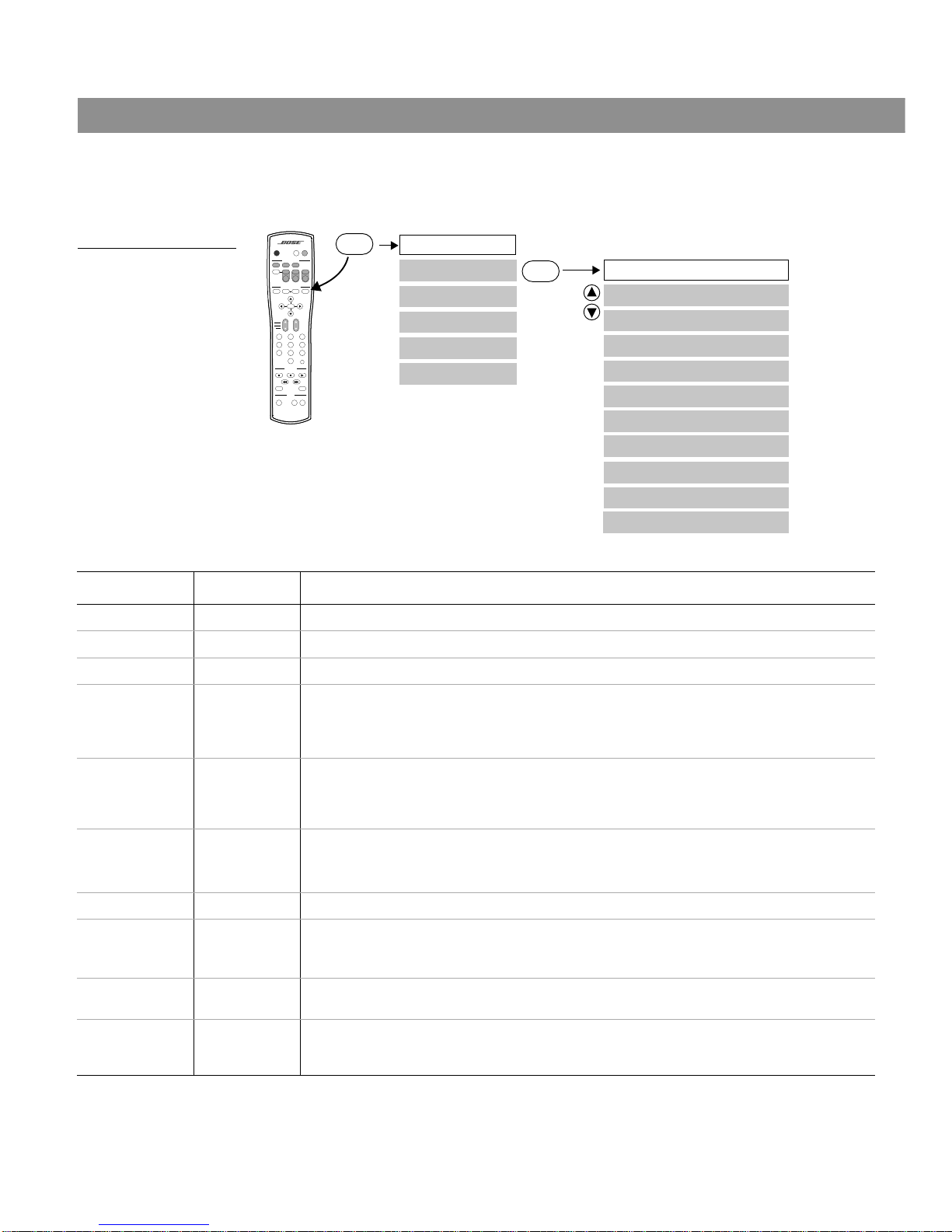
Changing DVD play options
While playing a DVD movie, there are several play options that can be changed. Figure 6
shows you a map to the DVD Play Options menu.
Figure 6
The DVD Play options menu
Settings: DVD Play Options
Title
Chapter
Title Time
Audio Track
Time Display
Motion Control
Subtitle Language
Camera Angle
Subtitle
Settings
Enter
AUDIO
SurroundSpeakers
SOURCE / INPUT
MENU / NAVIGATION
Seek
Volume
PLAYBACK
Pause PlayStop
Channel
Chapter
Preset
Track
Previous
Tune
Guide Exit
PowerPowerPower
TV Input
DVD
Menu
Repeat
FM/AM
Tape
2-3-5
+
-
Mute
Mute
All
Enter
1203
456
789
Shuffle
Settings
CD/DVD
AUXVCRTV
On
Off
DVD Play Options
Settings (DVD)
AB Repeat
Menu Item Settings What each setting does
Title: __ of __ Chooses the movie title that corresponds with the number you entered.
Chapter: __ of __ Chooses the movie chapter that corresponds with the number you entered.
Title Time: 00:00:00 Allows you to enter and go directly to an elapsed or remaining time in a movie.
Time Display: Elapsed
Remaining
Displays elapsed time in the media center window and in the on-screen DVD Status
window.
Displays remaining time in the media center window and in the on-screen DVD Status
window.
Motion Control: <<Scan/<<4x/
<<2x/Pause/
Play 1x/2x>>/
4x>>/Scan>>
Chooses direction and speed of DVD playback (Scan = 8x).
Audio Track: Track __ Chooses one of the available sound tracks on the DVD.
Note: Many DVDs will not allow you to make this selection here. If available, use the
setup menu on the DVD disc you are playing. To do this, press the DVD Menu button.
Camera Angle __ of __ Chooses one of the available camera angles on the current DVD.
Subtitle: On
Off
Displays subtitles in the lower portion of your TV screen.
Hides subtitles. Use this setting if you choose to use automatic subtitles (see “DVD
setup submenu” on page 34).
Subtitle
Language:
Lang __ Chooses one of the available subtitle languages on the current DVD.
AB Repeat Repeats a specified section of the DVD movie. Move to point “A” in the movie and
press Enter. Then, move to point “B” in the movie and press Enter. The specified
scene is repeated until you press Enter, Play, or Stop.
AM259776_02_V.pdf • April 23, 2002
Page 25
25
Changing System Settings
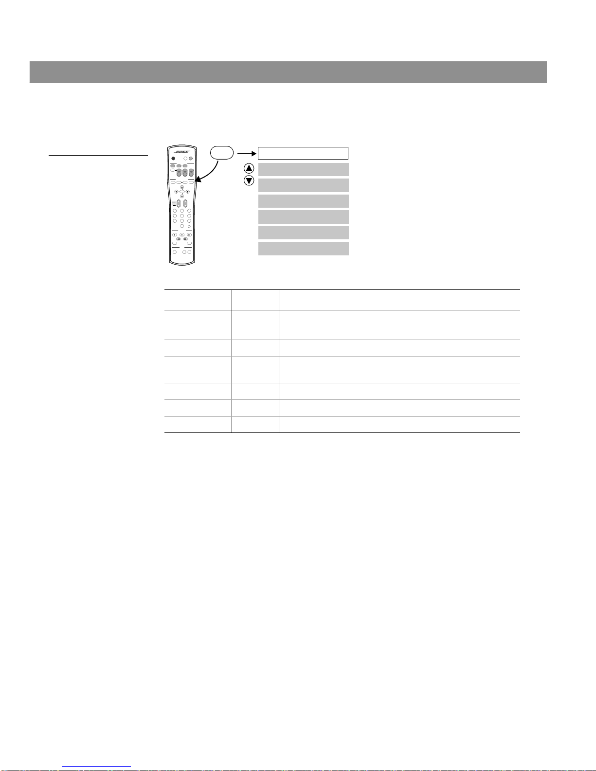
Changing CD settings
To change the CD settings, press the Settings button while the CD source is selected.
Figure 7 shows you a map of the CD settings menu.
Figure 7
The CD settings menu
Menu Item Settings What each setting does
Sleep Timer: Off
00:00
Timer not active.
Turns system off after set time expires (10 to 90 minutes).
Track: __ of __ Chooses a CD track.
Track Time: 0:00:00 Chooses a time in the current CD track. Use the numeric
keypad to enter a specific time.
CD Status: Displays information about the CD source.
Audio Setup See “Making audio adjustments” on page 29.
System Setup See “Changing the system setup” on page 32.
Sleep Timer
Track
Track Time
System Setup
CD Status
Audio Setup
Settings
AUDIO
SurroundSpeakers
SOURCE / INPUT
MENU / NAVIGATION
Seek
Volume
PLAYBACK
Pause PlayStop
Channel
Chapter
Preset
Track
Previous
Tune
Guide Exit
PowerPowerPower
TV Input
DVD
Menu
Repeat
FM/AM
Tape
2-3-5
+
-
Mute
Mute
All
Enter
1203
456
789
Shuffle
Settings
CD/DVD
AUXVCRTV
On
Off
Settings (CD)
AM259776_02_V.pdf • April 23, 2002
Page 26

26
Changing System Settings
Changing FM settings
To change the FM settings, press the Settings button while the FM sour ce is selected. Figure
8 shows you a map of the FM settings menu.
Figure 8
The FM settings menu
Menu Item Settings What each setting does
Sleep Timer: Off
00:00
Timer is not active.
Turns the system off after set time expires (10 to 90 minutes).
Station: _ _ _._ Tunes the FM tuner to the station frequency entered on the
numeric keypad.
Preset: __ of 25 Tunes the FM tuner to an FM preset station.
FM Status: Displays information about the FM source.
RDS info:
(For Europe only)
On
Off
Makes RDS information appear in the media center display.
Makes RDS information unavailable to the media center.
Output Mode Auto
Stereo
Mono
Automatically chooses stereo or mono for FM broadcasts
Always plays the FM broadcast in stereo (if available)
Always plays the FM broadcast in mono
Audio Setup See “Making audio adjustments” on page 29.
System Setup See “Changing the system setup” on page 32.
Sleep Timer
Station
Preset
System Setup
FM Status
Output Mode
Settings
AUDIO
SurroundSpeakers
SOURCE / INPUT
MENU / NAVIGATION
Seek
Volume
PLAYBACK
Pause PlayStop
Channel
Chapter
Preset
Track
Previous
Tune
Guide Exit
PowerPowerPower
TV Input
DVD
Menu
Repeat
FM/AM
Tape
2-3-5
+
-
Mute
Mute
All
Enter
1203
456
789
Shuffle
Settings
CD/DVD
AUXVCRTV
On
Off
Settings (FM)
Audio Setup
RDS Info
AM259776_02_V.pdf • April 23, 2002
Page 27

27
Changing System Settings
Changing AM settings
To change the AM settings, press the Settings button while the AM source is selected.
Figure 9 shows you a map of the AM settings menu.
Figure 9
The AM settings menu
Menu Item Settings What each setting does
Sleep Timer: Off
00:00
Timer is not active.
Turns the system off after set time expires (10 to 90 minutes).
Station: _ _ _ _ Tunes the AM tuner to the station frequency entered on the
numeric keypad.
Preset: __ of 25 Tunes the AM tuner to an AM preset station.
AM Status: Displays information about the AM source.
Audio Setup See “Making audio adjustments” on page 29.
System Setup See “Changing the system setup” on page 32.
Sleep Timer
Station
Preset
System Setup
AM Status
Settings
AUDIO
SurroundSpeakers
SOURCE / INPUT
MENU / NAVIGATION
Seek
Volume
PLAYBACK
Pause PlayStop
Channel
Chapter
Preset
Track
Previous
Tune
Guide Exit
PowerPowerPower
TV Input
DVD
Menu
Repeat
FM/AM
Tape
2-3-5
+
-
Mute
Mute
All
Enter
1203
456
789
Shuffle
Settings
CD/DVD
AUXVCRTV
On
Off
Settings (AM)
Audio Setup
AM259776_02_V.pdf • April 23, 2002
Page 28

28
Changing System Settings
Changing TV/VCR/AUX/TAPE settings
To change the settings for the TV, VCR, AUX, or TAPE source, press the Settings button while
one of these sources is selected. Figure 10 shows you a map of the settings menu when one
of these sources is selected.
Figure 10
The TV / VCR / AUX /
TAPE settings menu
Menu Item Settings What each setting does
Sleep Timer: Off
mm:ss
Timer not active.
Turns system off after set time expires (10 to 90 minutes).
TV, VCR, AUX or
TAPE Status:
Displays information about the TV / VCR / AUX / TAPE
source.
Audio Setup See “Making audio adjustments” on page 29.
Analog Input: -6/-3/0/3/6 Adjusts the TV / VCR / AUX / TAPE analog audio level. Use
this adjustment if an external analog source sounds much
louder or softer than the other sources.
Digital Input: -6/-3/0/3/6 Adjusts the TV / VCR / AUX / TAPE digital audio level. Use
this adjustment if an external digital source sounds much
louder or softer than the other sources.
System Setup See “Changing the system setup” on page 32.
Sleep Timer
TV/VCR/AUX/TAPE Status
Audio Setup
System Setup
Analog Input
Settings
AUDIO
SurroundSpeakers
SOURCE / INPUT
MENU / NAVIGATION
Seek
Volume
PLAYBACK
Pause PlayStop
Channel
Chapter
Preset
Track
Previous
Tune
Guide Exit
PowerPowerPower
TV Input
DVD
Menu
Repeat
FM/AM
Tape
2-3-5
+
-
Mute
Mute
All
Enter
1203
456
789
Shuffle
Settings
CD/DVD
AUXVCRTV
On
Off
Settings (Source)
Digital Input
AM259776_02_V.pdf • April 23, 2002
Page 29

29
Changing System Settings
Making audio adjustments
You can make some audio adjustments for each source individually. Figure 11 shows you
how to get to the Audio Setup menu:
1. Press the Settings button. A menu of the available settings for the current source
will be displayed on your TV screen.
2. Using the down navigation button ( ), scroll down the list and select (highlight)
Audio Setup
.
3. Press the Enter button and the audio settings will be displayed for the current source.
Figure 11
The audio setup
submenu
Settings: Audio Setup (source)
Movie EQ
Range Compression
Dolby Digital 1+1
Audio Status
Mono Decoding
Center Channel
Treble Compensation
Bass Compensation
Settings
Enter
AUDIO
SurroundSpeakers
SOURCE / INPUT
MENU / NAVIGATION
Seek
Volume
PLAYBACK
Pause PlayStop
Channel
Chapter
Preset
Track
Previous
Tune
Guide Exit
PowerPowerPower
TV Input
DVD
Menu
Repeat
FM/AM
Tape
2-3-5
+
-
Mute
Mute
All
Enter
1203
456
789
Shuffle
Settings
CD/DVD
AUXVCRTV
On
Off
Audio Setup
Settings (source)
Notes:
1. Does not appear for FM, AM, or CD.
2. Appears only when Dolby 1+1 is not available.
3. Appears only when a disc contains a Dolby Digital 1+1 audio track.
(Notes 1 and 2)
(Note 1)
(Notes 1 and 3)
Custom Equalization
Menu Item Settings What each setting does
Movie EQ: On
Off
Automatically sets bass and treble compensation for the proper playback of movie
sound tracks.
Movie EQ mode is Off.
Range
Compression:
On
Off
Automatically adjusts the volume to allow you to hear soft sounds (particularly dialogue)
and to prevent you from being overwhelmed by a loud special effect, such as an explosion. This feature is normally engaged when you turn the system on to DVD, TV, VCR,
AUX, or TAPE.
Range compression is off.
Dolby Digital 1+1: 1/2/Both Selects Track 1, Track 2, or both of the Dolby Digital 1+1 (dual mono) audio tracks.
AM259776_02_V.pdf • April 23, 2002
Page 30

30
Changing System Settings
Mono Decoding: On
Off
Automatically engages Bose® Videostage® 5 mono decoding circuitry when a Dolby
Digital bitstream indicates that it contains a mono program. This feature can process a
one-channel program into five-speaker sound, directing the signals so that dialogue
remains locked on-screen, while music and ambient effects fill the room. You experience a surround sensation, providing extra enjoyment when you watch older (that is,
pre-stereo) movies. This feature can be used for mono TV shows and movies when you
select TV, VCR, AUX, or TAPE.
Mono decoding is off.
Center Channel: –8 to 8 Focuses or softens the presentation of center-channel sound. In 2-speaker mode “--”
appears instead of a numeric value.
Audio Status: Displays system audio information. See the example in Figure 12.
Custom
Equalization
On
Off
– –
Makes audio adjustments based on the custom equalization process performed when
you played Disc 2. These audio adjustments compensate for your room furnishings,
speaker placement, and listening locations you selected during the process.
Erases the custom equalization adjustments and reverts to the settings that come with
the system.
Note: After choosing Of
f, press Erase on the media center within five seconds. This
erasing is not reversible. To restore the custom equalization adjustments, you must run
and complete the process on Disc 2 again.
You have not performed the custom equalization process on Disc 2.
Treble
Compensation:
–14 to +14
After custom
equalization:
–9 to +6
Decreases (–) or increases (+) the treble sound.
Rooms with few sound-absorbing furnishings, especially those with bare
floors and walls, may sound overly shrill or “bright.” Decreasing the treble
sound can be useful. Conversely, rooms with a lot of sound-absorbing
furnishings, such as upholstered furniture, wall-to-wall carpet, or heavy
drapes, can sound “dull” and may benefit by increasing the treble sound.
Different source materials, such as DVDs, CDs or radio stations, may also
vary in the amount of treble they have.
You can decrease the treble sound by lowering this setting to a negative
value from –1 to –14. T o increase the treble, raise this setting to a positive
value from +1 to +14.
Note: Completion
of the custom equalization process
compensates for
your room acoustics. Subsequently,
the treble and bass
controls operate
only over the range
from –9 to +6 and
should only be
needed for occasional adjustments
due to source material variations.
Bass
Compensation:
–14 to +14
After custom
equalization:
–9 to +6
Decreases (–) or increases (+) the bass sound.
Placement of the Acoustimass® module affects the amount of bass you
hear . Placing the module closer to the corner of the room will increase the
bass. Moving the module away from the corner will decrease the bass.
Different source materials, such as DVDs, CDs or radio stations, may also
vary in the amount of bass they have.
You can decrease the bass sound by lowering this setting to a negative
value from –1 to –14. To increase the bass, raise this setting to a positive
value from +1 to +14.
Menu Item Settings What each setting does
AM259776_02_V.pdf • April 23, 2002
Page 31

31
Changing System Settings
Figure 12
Status example: DVD audio
setup settings
Settings: Audio Setup (DVD)
Movie EQ: On
Range Compression: On
Audio Status:
Mono Decoding: On
Center Channel: 0
Displays information about volume and other
adjustments.
selects item
Audio
Volume: 55
Mute: OFF
Zone: 1
Room: A
Speakers: 5
Surround: +3
Treble Compensation: 0
Bass Compensation: 0
Custom Equalization: On
AM259776_02_V.pdf • April 23, 2002
Page 32

32
Changing System Settings
Changing the system setup
Press the Settings button to open the Settings menu on your TV screen. Using the down
arrow button ( ), scroll down the list and select (highlight) System Setup
. Press the Enter
button to display the System Setup menu. This section explains each item in the setup menu
in detail.
Figure 13
Map of the System Setup
Menus
Settings
Enter
AUDIO
SurroundSpeakers
SOURCE / INPUT
MENU / NAVIGATION
Seek
Volume
PLAYBACK
Pause PlayStop
Channel
Chapter
Preset
Track
Previous
Tune
Guide Exit
PowerPowerPower
TV Input
DVD
Menu
Repeat
FM/AM
Tape
2-3-5
+
-
Mute
Mute
All
Enter
1203
456
789
Shuffle
Settings
CD/DVD
AUXVCRTV
On
Off
Display Brightness
Display Language
DVD Setup
Record Out Format
Optical Source
Optical Input
Remote Control Setup
Send IR Commands
TV Power
Receive IR Commands
Tuner Spacing
Video Format
Aspect Ratio
Video Output
Video Black Level
Zone 2 Protocol
Zone 1 Protocol
DVD Autoplay
Auto Select Audio Track
Auto Subtitle
Parental Control Setup
Image Format
TV Brand
TV Device Code
AUX Device
VCR Brand
VCR Device Code
AUX Device Code
AUX Brand
Enter Password
Restrict Unrated Titles
Change Password
Change Password
Allowed Ratings
Confirm Password
Enter
Enter
System Setup
DVD Setup
System Setup
Settings (source)
Enter
Parental Control Setup
Enter
Change Password
Remote Control Setup
TV Tuner
AM259776_02_V.pdf • April 23, 2002
Page 33

33
Changing System Settings
System setup menu
The system setup menu contains settings that affect the entire system.
Menu Item Settings What each setting does
Display Brightness: 1 to 7 Determines the brightness level of the media center display (7 = brightest).
Display Language: English Presents on-screen display menus in the selected language.
Optical Source: TV / AUX /
VCR / TAPE
/ NONE
Assigns the OPTICAL INPUT to one of the four sources.
Optical Input: –6/–3/0/3/6 Adjusts the optical audio input level to match the input from the other sources.
Record Out Format: Original
PCM
No processing applied for RECORD DIGITAL OUTPUT.
Presents 2-channel, mixed-down Pulse Coded Modulation (PCM) on the
RECORD DIGITAL OUTPUT.
TV Power: Auto
Manual
Automatically turns on your TV whenever a video source is selected (TV on/off
detector required).
You must turn on your TV separately.
Send IR Commands: Off
On
No IR commands are sent by your system to control your TV, VCR and AUX
components.
Your system sends IR commands for all connected devices. This setting may
be useful to teach LIFESTYLE
®
remote commands to other IR remote controls.
Receive IR Commands: Off
On
IR commands are not received by your system.
IR commands from external equipment, such as universal remotes, are
received by your system.
Tuner Spacing: US
European
Sets channel spacing for AM/FM radio stations to the USA standard.
Sets channel spacing for AM/FM radio to the European standard (if available).
Video Format: NTSC
PAL
Sets video format for NTSC monitors.
Sets video format for PAL monitors.
Video Black Level: Normal
Extended
Sets the black level appropriate for most TVs.
Sets a black level that may be preferred for DVD playback on some TVs.
Video Output: Normal
YPbPr
Provides a video output at the COMPOSITE and S-VIDEO connectors.
Provides component video output using the COMPOSITE and S-VIDEO con-
nectors (component video adapter required).
Zone 1 Protocol: Normal
Legacy
Provides the correct output at the SPEAKER ZONE 1 connector for the new
Acoustimass® module that came with your system. Always use “Normal” for
zone 1.
Not used in zone 1 for this system.
Zone 2 Protocol: Normal
Legacy
Provides the correct output (variable level) at the SPEAKER ZONE 2 connector
for Bose® powered speaker systems, such as Acoustimass 5P and Acoustimass 20P.
Provides the correct output (fixed level) at the SPEAKER ZONE 2 connector
for other Bose speakers that use the SA-1 LIFESTYLE® amplifier.
AM259776_02_V.pdf • April 23, 2002
Page 34

34
Changing System Settings
DVD setup submenu
The DVD setup submenu lists options for how the DVD player should operate, including
Parental Control.
Parental control setup submenu
The parental control submenu lists options for how to restrict access to certain DVDs.
Menu Item Settings What each setting does
Auto Select
Audio Track:
On
Off
Where applicable, system automatically plays 5.1 channel
audio track when available on a DVD.
Audio track must be selected manually.
Auto Subtitle: On
Off
DVD subtitles are automatically displayed when the audio is
muted.
DVD subtitles are not displayed automatically.
DVD Autoplay: On
Off
DVD starts to play automatically when it is loaded into the
DVD player.
DVD is not started automatically when loaded.
Aspect Ratio: 4:3
16:9
If available, provides the 4:3 aspect ratio for standard TVs.
If available, provides the 16:9 aspect ratio for wide screen
TVs.
Image Format: Pan & Scan
Letterbox
Images are resized to fit a standard TV.
Images are resized to fit a wide screen TV.
If Aspect Ratio
is 16:9, Image Format is not applicable and
the setting is automatically shown as “--”.
Menu Item Settings What each setting does
Enter Password: _ _ _ _ Chooses a password to restrict access to DVDs above a
specified rating limit.
Restrict Unrated
Titles:
On
Off
Prevents viewing of unrated titles when password is set.
Allows unrated titles to play.
Create/Change
Password:
_ _ _ _ Lists options for how to create a new password or to change
a current password.
Allowed Ratings: 1 to 8 Blocks access to DVDs rated higher than the limit. See
“Using parental controls” on page 15.
AM259776_02_V.pdf • April 23, 2002
Page 35

35
Changing System Settings
Remote control setup submenu
This menu allows you to program your LIFESTYLE® remote to operate your TV, VCR and
cable/satellite box.
Menu Item Settings What each setting does
TV Tuner TV / VCR / AUX Choose a device that selects the channel for
viewing.
TV Brand: Brand1 / Brand2 / etc. Chooses the TV brand.
TV Device Code: Code1 / Code2 / etc. Chooses the IR code that the TV remote con-
trol uses. Press TV Power to test.
VCR Brand: Brand1 / Brand2 / etc. Chooses the VCR brand.
VCR Device Code: Code1 / Code2 / etc. Chooses the IR code that the VCR remote
control uses. Press VCR Power to test.
AUX Device: Cable / Satellite Chooses the type of device connected to the
AUX input.
AUX Brand: Brand1 / Brand2 / etc. Chooses the AUX component brand.
AUX Device Code: Code1 / Code2 / etc. Chooses the IR code that the remote control
of the AUX component uses. Press AUX
Power to test.
AM259776_02_V.pdf • April 23, 2002
Page 36

36
Reference
Changing the house code settings
Each LIFESTYLE® remote control uses a system of matching house codes to communicate
with its corresponding media center. If commands given from your remote ever conflict with
those of another nearby LIFESTYLE
®
system, you can easily set a new house code for your
system and its remote control(s) by doing the following:
1. Open the remote control battery cover and locate the miniature switches (Figure 14).
2. Move one or more of switches 1, 2, 3, or 4 in the opposite direction from its current
setting. Use a paper clip, ball point pen, or similar object.
Note: DO NOT change any other switch settings. Moving other switches may cause your
remote to not control your system.
3. Replace the battery cover.
4. Lift the media center door and press the All Off button.
5. Press and hold the Store key. Your current house code will appear in the media center
display window in the form of four rectangles which represent the positions of switches 1
through 4:
6. While holding the Store key, press any key on the remote control.
The display will change to show the new house code to confirm recognition of the
new code:
7. Release the Store key. The system remains off.
8. If you have additional remote controls, change the switches to match those of the first
remote control. It is not necessary to repeat steps 4-8.
Note: To verify your system’s house code, press Store while the system is off. The display
confirms the settings of switches 1-4.
Figure 14
Miniature house code
switches
HOUSE CODE:
Current house code = 0 0 0 0 (Switches 1 - 4 down.)
NEW HOUSE CODE:
New house code = 1 0 1 0
(Switch 1 up, 2 down, 3 up, and 4 down.)
123456789
123456789
House code switches (1-4).
Shown as set at the factory:
all switches down.
AM259776_02_V.pdf • April 23, 2002
Page 37

37
Reference
Setting up a second listening zone
Your LIFESTYLE® home entertainment system can direct sound from one or two sound
sources (such as CD, AM/FM tuner, TAPE, or AUX) to two different listening zones at the
same time.
What is a zone?
Each listening area, whether a room or a group of r ooms (including outdoor ar eas), is called a
zone. Your primary listening area is set up as zone 1.
What do I need for setting up a second zone?
• A Bose® powered speaker system that is compatible with your home entertainment system.
An existing stereo system can also be connected (special adapter required).
• The appropriate LIFESTYLE® system cable to connect the zone 2 speaker system to the
SPEAKER ZONES 2 connector on the rear panel of the media center.
• A second LIFESTYLE
®
system remote control to operate the zone 2 sound.
See your dealer or contact Bose for information on obtaining additional powered speakers,
remote controls, cables, and adapters for connecting additional equipment.
How do I set up a second remote to control zone 2?
1. Remove the battery compartment cover from the back side of the zone 2 remote.
2. Locate miniature switches 5 through 9 (Figure 15) and set them according to the table.
3. Make sure the house code switches (1, 2, 3, and 4) match those on your first remote.
4. Re-install the battery compartment cover back.
Figure 15
Miniature zone code
switches
123456789
123456789
Zone 1 & 2 Switch Settings
56789
To control zone 1: Down Up Down Down Down
To control zone 2: Up Down Up Up Down
Set switches 1-4 to match the settings
of 1-4 in your ZONE 1 remote.
Set switches 5-9 for ZONE 2.
AM259776_02_V.pdf • April 23, 2002
Page 38

38
Reference
Taking care of your LIFESTYLE
®
system
Caring for your system may include:
• Cleaning the system’s enclosures
• Cleaning your compact discs
• Replacing the remote control batteries
Cleaning the media center
• Use only a soft, dry cloth to clean the outside of the media center.
• Do not use any solvents, chemicals, or cleaning solutions containing alcohol, ammonia, or
abrasives.
• Do not allow liquids to spill into any openings.
• Do not use any sprays near the system.
Cleaning the speakers
• Clean the surface of your speakers with a soft, damp cloth. You can use an ammonia-free
window cleaner on a soft cloth to maintain the finish.
• Do not use any sprays near the system. Do not use any solvents, chemicals, or cleaning
solutions containing alcohol, ammonia, or abrasives.
• Do not allow liquids to spill into any openings.
• The speaker grille panels require no special care, although you may vacuum them car efully,
if necessary.
Cleaning discs
• Handle discs by their edges to prevent fingerprints and scratches (Figure 16).
• To remove stains or fingerprints from the surface of a disc, use a soft, lint-free, dry cloth.
Wipe in straight movements from the center of the disc to the outside. Do not use any
chemical products; they can damage the disc.
• Do not write on or attach labels to the surface of the disc.
• To minimize exposure to dust and dirt, replace discs in their cases after use. Store each
disc in its case, out of direct sunlight, high temperatures, and humidity.
Figure 16
Handling and
cleaning a disc
AM259776_02_V.pdf • April 23, 2002
Page 39

39
Reference
Replacing the remote control batteries
Replace the batteries when the remote control stops operating or its range seems reduced.
Alkaline batteries are recommended.
1. Slide open the battery compartment on the back of the remote (Figure 17).
2. Insert four AAA or IEC-LR3 1.5V batteries, or the equivalent, as shown. Match the + and –
symbols on the batteries with the + and – markings inside the compartment.
3. Slide the battery compartment cover back into place.
Figure 17
Installing the remote
control batteries
Troubleshooting
+
+
+
+
Battery
compartment
cover
Battery
compartment
AAA batteries (4)
Problem What to do
System doesn’t do anything
• Make sure the power connector is inserted securely into the media center, the power
cord is inserted securely into the Acoustimass
®
module, and the power pack and power
cord are plugged fully into operating AC wall outlets.
• Be sure to select a source (CD/DVD, AM/FM, etc.).
• Unplug the media center power supply for 60 seconds, then reconnect it. This allows the
unit to reset itself after a power surge or power interruption.
No sound • Increase the volume.
• Check to see if MUTE is lit on the display. If it is, press the Mute button on the remote
control to unmute the sound.
• Make sure the audio input cable is firmly seated in the media center SPEAKER ZONE 1
jack and the multi-pin connector on the other end is firmly seated in the Acoustimass
module AUDIO INPUT jack.
• Check speaker connections.
• Turn the media center off for 60 seconds, then on again, to restore communication
between the media center and the speakers.
• Check the connections for any external components. Make sure to select the correct
source for the desired input.
• Be sure the disc is placed correctly, label-side up, in the CD tray.
• Connect the FM and AM antennas.
• Make sure that the power switch on the Acoustimass module is set to ON (I).
AM259776_02_V.pdf • April 23, 2002
Page 40

40
Reference
No sound from center
speaker
• Make sure the center speaker cable is connected at both ends.
• Select 3- or 5-speaker mode.
Too much sound from
center speaker
• Decrease the Center Channel setting in the Audio Setup menu. See “Making audio
adjustments” on page 29.
No sound from surround
speakers
• Select 5-speaker mode.
• Press Surround +
• Make sure the video sound source is stereo and surround-encoded, and the component
used (TV, VCR, etc.) is stereo.
Surround speakers are too
loud
• In 5-speaker mode, press Surround –.
• Make sure that the left and right front speakers are connected to the front speaker jacks
(blue) and the left and right surround speakers are connected to the surround speaker
jacks (orange).
Remote control is inconsistent or does not work
• Check batteries and their polarity (+ and –). See “Replacing the remote control batteries”
on page 39.
• Operate the remote control closer to the media center.
• Move the remote (or the media center) a few feet to avoid an area of “dead spots.” See
note under “The remote control” on page 7.
• Make sure the media center power cable is firmly seated, uncoiled, and extended as
much as possible.
• Make sure the remote control and media center house codes match. See “Changing the
house code settings” on page 36.
System turns on by itself,
or behaves erratically
• Change the house code setting to prevent signals from conflicting with another nearby
LIFESTYLE
®
system.
• See “Changing the house code settings” on page 36.
Radio does not work • Make sure antennas are connected properly.
• Move AM antenna at least 20 inches (50 cm) from the media center.
• Adjust antenna position to improve reception.
• AM antenna must be upright.
• Move antennas farther from media center, TV, or other electronic equipment.
• You may be in an area of weak signal coverage.
The disc does not play • Check to see if the play symbol in the display is lit.
• After pressing the CD/DVD button, wait a few seconds before pressing Play.
• Make sure the disc is properly inserted (label side up).
• Eject the disc and try loading it again.
• The CD may be dirty. See “Cleaning discs” on page 38.
• The CD may be defective. Try another CD.
Problem What to do
AM259776_02_V.pdf • April 23, 2002
Page 41

41
Reference
FM sound is distorted • Adjust antenna position to reduce interference.
FM sound is noisy in sur-
round mode
• Weak FM stations will produce static in the surround speakers. Select the 2-speaker
mode to minimize noise.
Sound is distorted • Make sure speaker cables are not damaged and the connections are secure.
• Reduce the output level from any external components connected to the media center.
No tape, CD, VCR, or TV
sound.
• Check the connections.
• Make sure the component is turned on.
• Refer to the component owner’s manual.
You forgot your password • Enter a password of 2673 to access the parental controls and then create a
new password.
Media center display says:
NOT CONNECTED
• Make sure the audio input cable is firmly seated in the media center
SPEAKER ZONE 1 jack.
LIFESTYLE
®
remote does
not control your TV, VCR,
cable/satellite box, or
other external component.
• Make sure correct codes are set. See “Programming your LIFESTYLE® remote to control your TV” on page 19.
• Make sure that the front of the media center is not obstructed. The IR emitters that send
commands to your external components are behind the front panel display.
• If you still cannot control your external components successfully, you may need to connect the external IR emitter, included with your system, to the IR EMITTER jack on the
rear panel of the media center. See “Connecting the optional IR emitter cable” in your
LIFESTYLE
®
Installation Guide.
Your TV turns on and off
unexpectedly.
• Reposition the TV on/off detector on the back of your TV.
• Verify that the TV on/off detector is working properly by choosing TV Status in the
Settings (TV)
menu. When you turn on your TV, the status line that reads, “Detected TV
Power: Off” should change to “Detected TV Power: On”.
Problem What to do
AM259776_02_V.pdf • April 23, 2002
Page 42

42
Reference
Technical information
Media Center power pack power rating
USA/Canada: 120V 0.55A 50/60 Hz 33VDC 1.1A
Speaker system power rating
USA/Canada: 100-120V 50/60 Hz 350W
Media center inputs
TAPE: 2Vrms, maximum
AUX: 2Vrms, maximum
VCR: 2Vrms, maximum
TV: 2Vrms, maximum
DIGITAL: SPDIF (1 each for TV, VCR, TAPE, and AUX)
COMPOSITE VIDEO: NTSC or PAL format 1V
p-p
with sync 75 Ω
S-VIDEO: Luminance 1V
p-p
, Chrominance 0.3V
p-p
OPTICAL INPUT: SPDIF digital, mapped to input
FM antenna: 75 Ω
AM antenna: 12µH
TV SENSOR: Scan frequency sensing
Media center outputs
SPEAKER ZONES 1 and 2: Variable audio, user selectable
RECORD L and R: Fixed audio
RECORD DIGITAL: SPDIF
OPTICAL OUTPUT: SPDIF, –15 to –21 dbm
COMPOSITE VIDEO: NTSC or PAL 1V
p-p
with sync 75 Ω
S-VIDEO: Luminance 1V
p-p
, Chrominance 0.3V
p-p
Component video: NTSC or PAL 1V
p-p
with sync on Y
Remote control range
65 ft (20 m)
Dimensions/Weights
Finish
Media center: Aluminum
Cube speakers: Polymer painted
Acoustimass module: Vinyl veneer, Polymer
Media Center: 15.8" W x 11.0" D x 3.5" H
(40.1 cm x 27.9 cm x 8.9 cm)
8.2 lb (3.7 kg)
Cube speakers:
(2-wire conn.)
3.1" W x 4.0" D x 6.2" H
(7.8 cm x 10.2 cm x 15.7 cm)
2.4 lb (1.1 kg)
Cube speakers:
(plug-in conn.)
2.2" W x 3.2" D x 4.4" H
(5.6 cm x 8.1 cm x 11.2 cm)
1.0 lb (0.5 kg)
Acoustimass
®
module: 8.0" W x 24.5" D x 16.0" H
(20.3 cm x 62.2 cm x 40.6 cm)
35.9 lb (16.3 kg)
AM259776_02_V.pdf • April 23, 2002
Page 43

43
Reference
Accessories
For information on speaker mounting brackets and stands, additional remote controls, and
connecting additional Bose® powered loudspeakers, contact your Bose dealer or call Bose
customer service. See the address and phone number list included with your system.
Warranty
Your LIFESTYLE® home entertainment system is covered by a transferable warranty . See your
warranty card for details. Please be sure to fill out the information section on the card and
mail it to Bose.
Contacting customer service
For additional help in solving problems, contact Bose Customer Service. See the address and
phone number list included with your system.
AM259776_02_V.pdf • April 23, 2002
Page 44

©2002 Bose Corporation, The Mountain,
Framingham, MA 01701-9168 USA
259776 AM Rev.02 JN21093
AM259776_02_V.pdf • April 23, 2002
Page 45

" ,
"""
£liIiSBiiAti./
iJJilJD
H~lJiJe
Smlem-aimlJiJeml
B~slelJiJs
,,~
"~x"'"
"""x",,,,>;;%,<
;1m""
",~"",
Of"""__
<~,,,
,,~'"=~"§~
'"
"'"
",-«';"n,'O
~y'"
~
~
~
"' x ~" _
Imstallatiom
Guide
Guia
de
instalacion
Notice
d'installation
Page 46

A WARNING:
To
reduce the riskoffire or electric shock, do notexpose the systemtorain ormoisture.
To reduce the risk of fire or electric shock, do not expose the system to rain or moisture.
THE
CAUTION: TO REDUCE
DO
NOT
REMOVE COVER (OR BACK).
NO
USER-SERVICABLE PARTS INSIDE.
REFER SERVICING
These CAUTION marks are located on your
These CAUTIQN marks are located on your LIFESTYLE5 media center and AcoustimassB module enclosures:
The lightning flash with arrowhead symbol, withinanequilateral triangle, is intendedtoalert the usertothe presence
The lightning flash with arrowhead symbol, within an equilateral triangle, is intended to alert the user to the presence of
uninsulated dangerous voltage within the system enclosure that may beofsufficient magnitudetoconstitute a risk
&
~
A CAUTHON:
Class'1Haser
The
UCT according
UCT according to EN 60825-I A994 -i- Al 1. The CLASS 1 LASER PRQDUCT label is located
on the bottom ofthe media center.
on the bottom of the media center.
A CAUTION: Use
those specified herein
or repaired by anyone except properly qualified service personnel.
or repaired
Class B
This Class B digital apparatus meets all requirements ofthe Canadian Interference-Causing Equipment Regulations.
This Class B digital apparatus meets all requirements of the Canadian Interference-Causing Equipment Regulations.
uninsulated dangerous voltage within the system enclosure that may be of sufficient magnitude to constitute a risk of
electric shock.
electric shock.
Ia\,
The exclamation pointwithinanequilateral triangle,asmarked on the system,isintendedtoalert the usertothe pres-
The exclamation point within an equilateral triangle, as marked on the system, is intended to alert the user to the pres-
enceofimportant operating and maintenance instructionsinthis owner's guide.
ence of important operating and maintenance instructions in this owner’s guide.
To
prevent electric shock, match wide bladeofplugtowide slot, insert fully
= To prevent electric shock, match wide blade of plug to wide slot, insert fully
product
DVD
player contained within the media center is classified as a CLASS 1 LASER PROD-
toEN60825-1 :1994
Use of controls or adjustments or performance of procedures other than
of
ified herein may result in hazardous radiation exposure. The compact disc player should not be adjusted
by
anyone exceptproperly qualified service personnel.
emissions
within the media center is classified as a CLASS 1 LASER PRQD-
controlsoradjustmentsorperformanceofprocedures other than
may
resultinhazardous radiation exposure.
limits
RISK OF ELECTRIC SHOCK,
TO
QUALIFIED PERSONNEL.
L1FESTYLE®
-I-
A11. The CLASS 1 LASER PRODUCT label is located
media center and Acoustimass® module enclosures:
AFIN DE PREVENIRUNCHOC
LE COUVERCLE ARRIERE. IL NE SE TROUVE
LE COUVERCLE ARRliRE. IL NE SE TROUVE A L’INTiRIEUR
AUCUNE PIECE POUVANT ETRE REPAREE PAR
AUCUNE PI&X POUVANT iTRE RtPARgE PAR
L'USAGER. S' ADRESSER
The
compactdisc playershould notbeadjusted
ELECTRIQUE NE PAS ENLEVER
AL'INTERIEUR
A
UN
REPARATEUR COMPETENT.
CLASS
'I
KLASSE 1
N 1
LUOKAN
1
KLASS 1
lASER
PRODUCT
LASER
PRODUKT
LASER LAlTE
LISER APPARAT
LASER APPARAT
Batteries
Please dispose of used batteries properly, following any local regulations. Do not incinerate.
Please disposeofused batteries properly, following any local regulations. Do not incinerate.
Additio81aH
See the additional instructions on the
See the additional instructions on the Important Safety Information sheet enclosedinthe shipping carton.
PBease
Please take the time to follow this owner’s guide carefully. It will help you set up and operate your system properly, and enjoy all
Please take the timetofollow this owner's guide carefully. It will help you set up and operate your system properly, and enjoy all
of
its advanced features. Save your owner's gUide for future reference.
A CAUTION: No naked flame sources, such as lighted candles, should be
safety
read
dvanced
No naked flame sources, such as lighted candles, should be placed on the apparatus.
information
lmporfant Safety Mormation
this
oW81er's
features. Save your owner’s guide for future reference.
guide
sheet enclosed in the shipping carton.
placed
on the apparatus.
of
of
For
your
Serial numbers are located on the bottom of the media center and the bottom panel of the; ~~~us~irn~ss module.
Serial numbers are located on the bottom of the media center and the bottom panel of the Acoustimass module.
Media center serial number:
Media center serial number: Acoustimass module serial number:
Dealer name:
Dealer name: Dealer
Bose@ recommends that you keep your sales slip and warranty card together with this guide.
Bose®
02002 Bose Corporation. No part of this work may be reproduced, modified, distributed or othetwise used without prior wriflen permission.
©2002
Manufactured under license from Dolby Laboratories. “Dolby” and the double-D symbol are trademarks of Do/by Laboratories. Confidential
Manufactured under license from Dolby Laboratories. "Dolby"
Unpublished Works. 01992- 1997 Do/by Laboratories. A// rights reserved.
Unpublished Works. ©1992-1997 Dolby Laboratories. Allrights reserved.
“DTS” and ‘DTS Digital Surround” are registered trademarks oi Digital Theater Systems, Inc.
"DTS"
and
MEG Layer-3 audio compression technology licensed by Fraunhofer I/S and THOMSON multimedia.
MPEG Layer-3 audio compression technologylicensedbyFraunhofer liS
This product incorporates copyright protection technology that is protected by mefhod c/aims of certain U.S. patents and other inte(lecfual prop-
This
product
erty rights owned by Macrovision Corporation and other rights owners. Use of this copyright prot?ction technology musl be authorized by Mac-
erty rights
rovision Corporation, and is intended for home and other limited viewing uses on/y unless otherwIse authorized by Macrovision Corporation.
rovision Corporation,
Reverse engineering or disassembly is prohibited.
Reverse engineeringordisassembly is prohibited.
This product incorporates copyright protected technology and other infelleciual property rights owned by Cirrus Logic, /nc. and is subject to
This
product
copyright protection of the U.S. as well as other licensing restrictions and protections. Use of this copyright protected fech?ology is //m/ted solely
copyrightprotectionofthe
to use with the Cirrus Logic integrated circuits incorporated in this product. Reverse engineering or disassembly IS proh/b/ted.
to use with the Cirrus Logic integrated circuits incorporatedinthis product. Reverse engineeringordisassemblyis prohibited.
2
2
records
recommends that you keep your sales slip and warranty card together with this guide.
Bose Corporation. No
"DTS Digital Surround" are registered trademarksofDigital Theater Systems, Inc.
incorporates copyrightprotection technology thatisprotectedbymethod claimsofcertain
ownedbyMacrovision Corporation
and
incorporates copyright protected technology
partofthis work
is intended for home
U.S.as wellas otherlicensing restrictions
-.
Dealer phone:-.
maybereproduced, modified, distributedorothe/wise used without prior written permission.
and
and
otherrights owners. Useofthis copyright protection technology
and
other limited viewing uses only unless otherwise authorizedbyMacrovision Corporation.
and
otherintellectual property rights
~c~us~irn~ss mcsdule serial number: _.
phone:__
the double-D symbolare trademarksofDolbyLaboratories. Confidential
and
THOMSON multimedia.
and
protections. Useofthis copyright protected technologyis limited solely
ownedbyCirrus Logic, Inc.
Purchase date:
Purchase date: _
U.S.
patents
and
otherintellectualprop-
mustbeauthorizedbyMac-
and
is subject to the
-
t/?e
Page 47

Where
to
find
"ms
Introduction " ". . . . . . . . . . . . . . . . . . . . . . . . . . . . . . . . . . . . . . . . . . . . .
..
4
Welcome " . . . . . . . . . . . . . . . . . . . . . . . . . . . . . . . . . . . . . . . . . . . . . . . . . . . . . . . . . . .
..
4
Region nurnbers ". . . . . . . . . . . . . . . . .
..
4
Types ofdiscs you can play " ". . . . . . . . . . . . . . . . . . . . .
..
4
Symbols usedinthis guide 4
System Installation.."....
.
"....
5
Getting started 5
Cables and accessories " . . . . . . . . . . . . . . . . . . . . . . . . . . . . . . . . . . . . . . . . . . . . . . .
..
6
Placing your speakers 7
Left and right front speaker placement 7
Center speaker placement . . . . . . . . . . . . . . . . . . . . . . . . . . . . . . . . . . . . . . . . . . . . . . . .
..
8
Surround speaker placement . . . . . . . . . . . . . . . . . . . . . . . . . . . . . . . . . . . . . . . . . . . . . .
..
8
Acoustimass® module placement 9
Placing your media center 10
Connecting the speakerstothe Acoustimass module
11
Making atwo-wire speaker connection . . . . . . . . . . . . . .. . . . . . . . . . . . . . . . . . . . . . . .
..
11
Making a plug-in cable speaker connection 12
Connecting the Acoustimass module
to
the media center 13
Connecting the antennas . .. . . . . . . . . . . . . . . . . . . . . . . . . . . . . . . . . . . . . . . . . . . . . . . . . ...14
Connecting
an
FM antenna . . . . . .... ,
,....................
14
Connecting the AM antenna 14
Connecting
to
a cable radio provider 14
Connecting your
TVtothe system . . . . . . . . . . . . . . . . . . . . . . . . . . . . . . . . . . . . . . . . . . . . ...15
Making audio connections
..
". . . . . . . . . . . . . . . . . . . . . . . . . . . . . . . . . . . . . . . . . . . . ...15
Making video connections
".
"15
Connecting your
VCRtothe system (optional) 16
Connecting your cable/satellite box
to
the system (optional)
17
Installing theTVon/off detector (optional) ". . . . . . . . . . . . . . . . . ...18
Turning
off
the
internal
speakersinyour
1'/
~
. Q v
o.
18
Making the temporary headset connection before connectingtopower 19
Connecting the system
to
power " . . . . . . . . . . . . . . . . . . . . . . . . . . . . . . . . . . ...19
Installing the remote control batteries "
"......................
20
Finishing the installation . . . . . . . . . . . . . . . . . . . . . . . . . . . . . . . . . . . . . . . . . . . . . . . . . . . . .
..
21
Save the headset for possible future use
".......................
22
Reference
....
"...................................................................
23
Using alternate system connections 23
To play
VCR
audio (notTVaudio) through your system " 23
To play
TV
audio through your system with
VCR
audio fedtothe
TV
24
Setting up a second listening zone 25
What is a zone? "
".............
25
What do I need for setting up a second zone?
".................
25
How do
i set up a speakersystem
in
a second zone? "
"..........
25
Connecting external equipment . . . . . . . . . . . . . . . . . . . . . . . . . . . . . . . . . . . . . . . . . . . . . . .
..
26
Connecting record/playback equipment " ". . . . . . . . . . .
..
26
Connecting other playback equipment "
".....
27
Using digital audio connections . . . . . . . . . . . . . . . . . . . . . . . . . . . . . . . . . . . . . . . . . . . . . . .
..
27
Using optical digital audio connections . . . . . . . . . . . . . . . . . . . . . . . . . . . . . . . . . . . . . . . . .
..
27
Connecting the optional
IR
emitter cable " 28
Accessories
"................................
28
Warranty " ". . . . . . . . . . . . . . . . . . . . . . . . . . . .
..
28
Contacting customer service
".........................................
28
Technical information 29
Page 48

Welcome
Region
Types
numbers
of
discs
Thank you for purchasing a
Of
y@a.m
h~ve
sa.m©©essfa.mliy
Set
Up
Ga.mide,
p~ge
21.
Of
ru@t,
the
ii1lst~li~ti@i1I.
Region numbers are assigned to ayers and discs a~~ordir~g to where they are sold.
Region numbers are assignedtoDVD
Look for the region number mark
Look for the region number marked on the carton or on the bottom of the mediacenter.
For example, a region 1 IX/ player should be marked like this:
For example, a region 1
Your system can play only discs marked with the same region number.
Your system can play only
you
can
The DVD player in your system can play the following types of discs:
The
@ Video DVDs
play
DVD
playerinyour system can play the following types ofdiscs:
©@i1Igr~ta.ml~ti@ns!
ii1lf@rm~ti@i1I
LiFESTYLE®
ni1lst~ned
provided
DVD
player should be marked like this: It+HH-+i!
DVD
discs marked with the same region number.
home entertainment system.
y@a.mw
m~w
UfESlYlEG'
Y@a.m
©~i1I
i1I@W
skipt@"finnshirug
@n
the
f@lI@wing
players and discs according to where they are sold.
he carton or on the bottom of the media center.
p~ges
system
will
a.msirug
the
ga.mide
irust~n~ti@i1I"
1¥@a.m
v n::n: 0
the
Qa.mi©k
thw@a.mgh
@i1I
the
Symbols
L . .J
used
C[DMPACT
@ Audio CDs 00
[DiGiTAL
o CD-Rs or CD-R/Ws
o MP3 CDs
in
this
1
I
, A box with dotted lines identities what parts may vary with different systems or in different
J
guide
The symbols that appear in this guide are intended to aid in your understanding of this mate-
The symbolsthat appearinthis guide
rial. Those symbols include:
rial. Those symbols include:
A boxwith dotted lines identifies what parts may vary with different systems
countries.
countries.
AlJiliK:D
are
intendedtoaidinyour understanding ofthis mate-
orindifferent
,4 gray circle with a number inside it indicates text that explains a similarly numbered step on
A gray circle with a number inside it indicatestext that explains a similarly numbered step on
the Quick Set Up Guide.
the Quick Set Up Guide.
4
4
Page 49

qnpow ~sswwgsno3~
Getting
started
After unpacking your new system, save all packing materials. The original packing materials
provide the safest way
to
transport your system if necessary.Ifany part of your system
is
missing orappears damaged, contact your authorized
Bose®
dealer immediately, or contact
Bose directly. Refer
to
the Bose address list included with your system.
The instructions in this section tell you how
to
connect your system as shown in Figure1.For
alternate systerrf connections, see "Using alternate system connections" on page 23.
Figure
"I
System connection diagram
Left front
speaker
Centerfront
speaker
Right
front
speaker
Cable TV
or
satellite Input
Right surround
speaker
VCR left & right audio
VCR video
AUX left & right audio (if available)
Rear speaker
outputs
TV left & right audio
r,m"~mm~~~~"""w,m,~,~m
;=~~~";;V~id~e~o='ou~t~u~t
~~-I
TV
TV
power
detector
I
Frontspeaker
outputs
Speaker
zone
i
output
Page 50

Cables
and
accessories
Figure 2
Cables
and
Cab/es and accessories
included with your system
included with your system
accessories
The following items are included with your system.
Surround speaker cables
Surround speaker cables
Front speaker cables
Front speaker cables
Stereo audio cable
Stereo audio cable
Video cable (6 ft)
Video cable(6ft)
TV on/off detector
TV on/off detector
~;
S-Video cable
S-Video cable
Rubber feet for
Rubber feet for
Acoustirnass’ module
Acoustimass® module
,
- - - --.- -.- - 1
r
cm ‘:‘*, 1
I
L ._--
Optional
OR
..
Rubber feet for
Rubber feet for
cube speakers
cube speakers
~._-
FM antenna
FM
-
-
-
antenna
IR
emitter cable
1,\
-_.-
.,
.J
I
Component video adapter
Component video adapter
” :,,‘
‘/
1’ , ’
/
#iscs1 &2 ’
Discs 1
<~\ ,’ ,
&2
._
,
-----
,-------_
; Media center power supply AC pawer cord
Media center power supply AC power cord I I
I
I
I
I
I
120 VAC power cord 230
(U~/~anada)
(US/Canada) (Europe)
I
230 VAC power cord 240
(UK/Singapore) (Australia)
L
6
Wledia center power supply
Media center power supply
...
----------,I-
115/230
dual power cords
dual powercords
(US/Europe)
(US/Europe)
-
VAG
230 VAC power cord I ( 120 V/AC: power cord
VAG
power cord I I 120
VAG
power cord 230
.,
, ,
I I
I I
I I
I I
I I
I I
I I
I I
I I
I I
I I
I I
I I
I I
---
,
- - -.. ..- _ - - --. .-
Acoustimass module AC power cord
Acoustimass module
VAG
power cord
I I (US/Canada)
I I
I I
I I (UK/Singapore)
.JL
VAG
power cord
Headset
for custam equalization process
for custom equalization process
115/230 VAC
dual power cords
dual power cords
(US/Europe)
(US/Europe)
Headset
AC
power cord
230 VAC power cord /
230 VAC power cord I
(Europe) I
240
VAG
power cord I
_
___
(Australia)
.
- - -1
I
I
I
I
I
I
I
I
I
I
I
I
I
I
I
I
I
I
..1
Page 51

your
speakers
When you place yourspeakers accordingtothe guidelines below, a combinationofreflected
and direct sound provides the audio atmosphere
of
a home theater.
You
may experiment with
the piacement and orientation
of
the speakerstoproduce the sound rnost pleasingtoyou.
A CAUTDON: Choose a stable
and
level surface for your speakers. Vibration can cause the
speakers
to
move, particularlyonsmooth surfaces like marble, glass, or highly polished
wood. If you arejJlacing the center speaker on top
of
the television, attach the rubber feet
provided
to
the bottomofthe speaker.
You
may obtain additionairubber feetbycontacting
Bose®
customer service. Refertothe Bose address list included with yoursystem.
Note:
00
not place a cube speakeronits side, as this diminishes performance.
Left
and
right
front
speaker
placement
To
best match sound and picture, the left and right front speakers should be placed at the
edge
of
the TV picture (Figure
3).
@
Place
tJ"",e
speakersupto3feet(1m)
from
the
edgeofthe
T'J
screen
and
line
themupvvith
the centerofthe TV screen.
Bose recommends a maximum distance
of
3 feet(1m)
from the edgeofthe TV screen so
that the sound does
not
become
too
separated from the picture.
You
may wishtovary this
distance based on room conditions and personal preference. The front cables allow the
cube speakers
to
be placed upto20 feet
(6.1m)from
the
Acoustimass® module.
@ Direct one cube
of
each speakerarray forward. Direct the other cube toward the wallorin a
different direction
to
create reflected sound. See the illustrationofreflected sound patterns
in Figure 40n page
8.
:3
Left surround
Page 52

Figure
Speakerplacement
Speaker placement and
reflection rays
4
and
Left
Left
surround
surround
Left
front
Center
Right
front
Acoustimass®
module
Right
Right
surroldncl
surrounc]
Center
The sound from the center speaker should appear to come directly from the center of the pic-
The sound from the center speaker should appeartocome directly from the centerofthe pic-
ture. The center speaker cable allows up to 20 feet (6.1 m) distance from the Acoustimass
ture. The center speaker cable allows up
module.
module.
1.
)
N@te:
of
the center speaker.
2. Align the speaker with the front of the TV screen (not pushed to the back of the TV).
2.
3. Birect each of the cubes slightly away from center, to create a wider area of direct sound.
3.
) N@te: Ifyou
the shelf. Placing speakers in an enclosed space can change the tonal quality of the sound.
the shelf. Placing speakersinan enclosed space can change the tonal qualityofthe sound.
Surround
The rear surround speakers create an area of sound around the listener. Place them in the back
The rear surround speakers createanareaofsound around the listener. Place theminthe back
half of your room. Direct the cubes slightly away from the listeners so that you cannot pinpoint the
half
exact location of the sound source. The surround cables allow up to 50 feet (15.2 m) distance
exact location ofthe sound source. The surround cables allow up
from the Acoustimass module.
from the Acoustimass module.
4. Place the speakers at ear height (when seated) or higher, if possible.
1.
2. Adjust the rear surround speakers to direct the sound to the front and back of the listener.
2.
speaker
lace -the center speaker directly above or below the center 04 the W screen, or a% the
Place the center speaker directly aboveorbelow the centeroftheTVscreen, or at the
lose& convenient location.
closest convenient location.
if it will sit directly on the TV be sure to attach the protective rubber feet to the bottom
Ifit will sit directly on the
placement
TV,besuretoattach the protective rubber feettothe bottom
to
20 feet
(6.1m)distance from the Acoustimass
e center speaker.
Align the speaker with the frontofthe TV screen (not pushedtothe backofthe
Direct eachofthe cubes slightly away from center,tocreate a wider areaofdirect sound.
:
If you put the speakers in a bookcase unit, be sure to place them al the front edge of
put
the speakers
speaker
of
your room. Direct the cubes slightlyaway from the listeners so that you cannot pinpointthe
Place the speakers at ear height (when seated) or higher, if possible.
Adjust the rear surround speakerstodirect the soundtothe front and backofthe listener.
in
a bookcase unit, be sure
placement
to
place them at the front edge
to50feet
(15.2m)distance
TV).
of
8
8
Page 53

3a~o d!~. hu alnpoLu
‘JOOIJ aya 6upeq
aya pue panln:, Al$qG!ls
sno&lKu”.Jo3 qgl\n ‘a6pa
s! afxyns s!yl .pua ycxzq
6UOl aya. uo a! XEld
aya uo alnpoLu aq~ puws
ION oa
Acoustimass@
module
placement
)
Note:
Nowisa
good
timetofind the serial numberon the bottomofthe module, before you
proceed. Copy thatnumber onto your warranty card
andinthe space provided on page 2
of
this guide.
Follow these guidelinestoselect a location
for
the Acoustimass module:
@ Place the Acoustimass module along the same wail as the
TV,orclosetothe same end
of
the room as the front speakers (see Figure
4).
)
Note:Toavoid interference with theTVpicture, place the Acoustimass module at least
18
inches (45em) from the
TV
.,
Place the Acoustimass module so thatthe grillewith the
Bose®
emblem faces into the room
or
along the walltoavoid blocking the sound outputorcreating
too
much bass.
@ For best bass performance, DO NOT place the Acoustimass module
at
equal distances
from
any
tvvo
vvallsorfromavvall
and
the
ceiling.
@ For convenience, you
may
wanttoslide the Acoustimass module undera tableorbehind a
cabinet. However,
DO
NOT allow furnitureordrapestoblock
the ventilation openingsofthe
module.
@ Place the Acoustimass modulewithin reach
of
the audio input cable, speaker cables, and
an AC power (mains) outlet.
@ Place the Acoustimass module on the floor on its long edge
or
layitdown
on its largest
side.
DO
NOT stand it on either end. See Figure
5.
5
and
wrong place-
BEST
For best ventilation,
place it on the long
edge, with connectors
facing the floor.
ALTERNATE
Place it on its largest
side.
DONaT
stand the moduleon the
back
end. This surface is
slightly curved and the
module may
tip
over.
DO NOT
stand the moduleon
the front grille. The
weight
of
the module
can
damage
the
grille.
@ Once you have selected a position for the module, place the four self-adhesive rubberfeet
nearthe cornersofthe bottom surface. The rubber feet provide increased stability and protection from scratches.
A CAUTiON: DO NOT cover the ventilation openings
of
the Acoustimass module.
The
slots on
the endprovide ventilation for the built-in electronic circuitry,
and
should notbeblocked.
A
__
. _ _ _
_..
.
..
. . .
..
..
. . • , , , ,
~
CAUTION:
Ihe
magnetic field trom the Acoustlmassmodule IS notan Immediate
nSk
to
your
video tapes, audio tapes,
and
other magnetic media. However, you shouldnot store tapes
directly on ornear the Acoustimass module.
Page 54

Placing
your
media
,)
center
Note:
you proceed. Copy that number onto your warranty card
page2of
page 2 of this guide.
Select a location for the media center, keeping
Select a loca’rion for the media center, keeping in mind the colliding g~i~~line~:
o Do not blockthe front
Nowis a
IVOW is a good time to find the serial number or) the bottom of the media centet; before
roceed. Copy that number onto your warranty card and in the space provided on
good
time to find the serial number on the bottomofthe media center, before
andinthe space provided on
this guide.
in
mind the following guidelines:
of
not block the front 04 the media cent
front cover and open the CD tray
nt cover and open the CD tray of the
that you can clearly view the display window
that you can clearly view the display wi
for a description
for a description of the front of the media center,
of
the media center. Make sure you allow enough roomtolift up the
of
the CD/DVD player. Also, position the media center so
the frontofthe media center.
Make WE yau allow enough room to lift up the
/DVD player. Also, position the me
to the right of the CD tray cover.
to
the rightofthe CD tray cover. See Figure 6
center so
8 Figure 6
Front~awresofmedm
center
center
o Place the media center close enough
Place the media center close enough to other sound ~~~r~e~ FV and VCB) %a allow for easy
cable connections. If you need additional audio and/or video cables
cable connections. If you need addi
components, see your dealeror call
components, see your dealer or call se@ customer service.
included with your system.
included with your system.
o Place the mediacenter within 30 feet
Place the media center within 30 feet (9.1 m) of the ~~~~~~irn~~~~ module (the length of the
audio inputcable).
audio input cable).
= For convenience, uniil your system is completely installed and tested, keep the media
,)
s
Note:
center where you have easy access to its rear connection panel.
center where you have easyaccess
Front
enough room to lift up this door.
enough room
For convenience, until your system is completely installed
cw- Make sure you have
nt
door
- Make sureyou have
to
lift up this door.
\
to
othersound sources
nal audio and/or video cables to connect all af your
Bose®
to
customer service. Refertothe Bose address list
(9.1m)of
the Acoustimass® module (the lengthofthe
its rear connection panel.
Display
this information while using your system.
this information while using yoursystem.
(TV
and
VCR)toallow for easy
to
connect allofyour
efer “6~ the EQX.Z a&%+ess list
and
tested, keep the media
window
- Make sure you can view
- Make sure you can view
10
10
Disc
open for you to insert a disc.
open for you
- Make sure nothing blocks this tray as it slides
tray
- Make sure nothing blocks this tray
to
insert a disc.
as
it slides
Page 55

Connecting
the
speakers
to
the
Acoustimass®
module
)
Note:
Before you startmaking system connections, make sure that the media center, the
Acoustimass module,
and
anyadditional equipment are not connectedtoAC
power.
The five dual-cube speakers that come with your system will either have a two-wire cable
connector (Figure
7)ora plug-in cable connector (Figure 8 on page 12). Identify your type
of
speaker and then follow the corresponding instructions.
)
N@te:
To
length~n
the speakercables, use heavy-duty
RCA
extension cables, or splicein18-
gauge or thicker
cord
(connecting +
to
-I-
and--to
-).Topurchase extension cables, see your
dealer
or
electronics store, or call Bosif' customerservice. Refertothe Bose address list
included with your system.
Makingatwo-wire
speaker
connection
In
a two-wire connection (Figure 7), the wire marked with a red collar is positive
(+)
and the
plain one is negative (-). These wires match the positive
(red)
and negative (black) terminals
on the back
of
each speaker.
)
Note:
The
surround speaker cables are joined together for your convenience, providing
an
easy-to-use cable for connecting the surround speakers.Torun the cablesindifferent directions from the Acoustimass module, simply pull apart the cables as needed.
_
..
---------
A two-wire connection type
speaker
\
Terminal tab
1. Match the correct cable
to
the corresponding speaker location. Front speaker cables
have blue connectors at one end, with L(left), R (right), or C (center) molded into the connectors. The red collars on the
+ wire are labeled
LEFT,
RIGHT,
and CENTER. Surround
speaker cables have orange connectors at one end, with L (left) or R (right) molded into
the connectors. The red collars on the
+ wire are labeled LEFT and
RIGHT.
2. Connect the wire end
of
one speakercable to the terminals on the rearofthe matching
speaker. Press the terminal tab on the back
of
the speaker and insert the marked wire
(+)
into the red terminal and the plain wire H into the black terminal. Release the tab
to
secure the wire. Repeat this step for eachofthe five speakers.
3. Connect each cable
to
the corresponding jack on the Acoustimass module (Figure 90n
page 12). Plug the blue connectors into the matching left front, center, and right front
jacks. Plug the orange connectors into the matching left surround and right surround
jacks.
Page 56

Makingaplug-in
In
a plug-in cable connection (Figure
In a plug-in cable connection (Figure 8), the positive and negative wires are oriented to ensure
proper polarity.
proper polarity.
cable
speaker
8),
the positive and negative wires
connection
are
orientedtoensure
Figure
A plug-in cable type
A plug-in cable type
speaker
speaker
Figure
Speaker connections to the
Speakerconnections to the
Acoustimass module
Acoustimass module
8
9
1.
Match the correct cabletothe corresponding speaker location. Front speaker cables
1. Match the correct cable to the corresponding speaker location. Front speaker cables
have blue RCA connectors at one end, with l (left), R (right), or C (center) molded into
have blue RCA connectors at one end, with L. (left), R (right), or C (center) molded into
both the RCA connectors and the speaker connectors at the other end. Surround
both the RCA connectors and the speaker contvxtors at the other end. Surround
speaker cables have orange RCA connectors at one end, with k (left) or R (right) molded
speaker cables have orange RCA connectors at one end, with l (left) or R (right) molded
into both the RCA connr;dors and the speaker connectors at the other end.
into both the RCA connectors and the speaker connectors at the other end.
2. Insert the speaker connector of each cable fully into the jack on the rear of each of the
2.
Insert the speaker connector of each cable fully into the jackonthe rear of each of the
five speakers. Match the ridge of the connector to the notch at the top of the jack.
five speakers. Match the ridge of the connector
3. Connect each cable to the corresponding jack on the ~cous~imass~ module (Figure 9).
3.
Connect each cabletothe corresponding jack on the Acoustimass® module (Figure
Plug the blue connectors into the matching left front, center, and right front jacks. Plug
Plug the blue connectors into the matching left front, center, and right front jacks. Plug
the orange connectors into the matching left surround and right surround jacks.
the orange connectors into the matching left surround and right surround jacks.
Front. speakers
Front speakers
Left
Center
Center
Right
Right
to
the notch at the top ofthe jack.
Surround speakers
Surround speakers
LeA Right
Left Right
9).
L
To SURROUND R
12
Page 57

the
Acoustimass®
module
to
the
media
center
Connect the Acoustimass moduletothe media centerwith the audio input cable (Figure 10).
)
N@'I;@):
Be sure that each connector is fully inserted into each jack.
1.
Plug the small black multi-pin connector(flat side facing up) into the SPEAKER ZONES
jack labeled
"1"
on the
backofthe media center.
2.
Insert the
te~ephone-style
RJ-45 connector on the other endofthe
audio input cable into
the AUDIO INPUT
jack
on theAcoustimass module. When properly connected, it should
lock in place.
)
N@'I;e:
Referto"Setting up a secondlistening zone" on
page25for information on connecting
a secondzone.
N@'I;e:
Press tabtorelease cable connector.
When
fully inserted into the jack, the connector
locks
in
place.
A CAUTHON: Do
not
place strain on the audioinput cable, especially on the connectiontothe
Acoustimass module. Placing excessive strain on the cable may cause damage
to
the cable
connection
at
the Acoustimass module.
When
disconnecting the cable from the Acoustimass
module,
be
sure to press the tab on the connector.
Page 58

Connecting
the
antennas
Connections for the
andFMantennas
and
FM
antennas
AM
The rear panelofthe media center provides connections for AM and
The rear panel of the media center ~r~vi~~~ connections far AM and FM an&nnas (Figure 1 I).
8e
suretounwrap the bundled antenna wires and straighten themasmuchaspossible
Be sure to unwrap the ~un~l~~ a~~~~n~ wires and ~~r~i~h~~n “Ihem as much as possible to
ensure the best reception.
ensure %he best recep%ion.
)
Note:
installer. Follow all safety instructions suppliedwith the antenna.
-
Outdoor antennas
* Outdoor antennas rnay be used. To install an outdoor antenna, consult a qualified
ler: Follow all safety instructions supplied with the antenna.
AM antenna
AM antenna
lead
maybeused.Toinstall an outdoorantenna, consult a qualified
FM
dipole
antenna lead
FM
antennas (Figure 11).
to
Connecting
Plug the connector on Zhe FM dipole antenna lead into the FM ~n~~~n~ jack. Spread ou”t: the
Plug the connector on the
antenna arms. Change “rhe ~ri~n~~~i~n sf “rhe antenna arms to get optimum FM recep”rion.
antenna arms. Change the orientation
Place the antenna as far from the media center and other ~orn~~n~~~~ as possible;.
Place the antenna as far from the media center and other components as possible.
Connecting
)
= To mount the AM antenna on a wall, follow the instruciions enclosed with the antenna.
Note:
1.
1. Plug the connector on the AM antenna lead into the AM antenna jack.
2.
2.
3.
3.
To
Plug %he connector art “the AM ~n~~n~~ lead into %he AM ~n~~nr~a jack.
Sand Zhe loop an”cenna art “the baset following “xhe in~~ruc~i~~~ enclosed wilh “the AM
Stand the loop antenna on the base, following the instructions enclosed with the AM
antenna.
antenna.
Move the AM loop antenna as far as ~~~~i~l~, at lead 20 inches (50 cm), from the media
Move the AM loop antennaasfar as possible, at least 20 inches
center, and al: IeasZ 2 fee% (60 cm) from the Acous”limass@ module. ~x~~rirn~n~ with the
center, and at least 2 feet
~rien~a~i~n of the loop for ~~~irnurn F&I reception.
orientation
Connecting
e cable TV providers make FM radio signals available ~hrQug~ “rhe cable service to your
Some cable TV providers make
e. This connedion is made to “the external FM jack on the back panel of the media center.
home. This connection is made
lo connect “co this service, co&act your cable TV provider for assistance.
To
connect to this service, contact your cableTVprovider for assistance.
u
)
r( Make sure that the cab/e radio installatior?<includes a signal splitter so that only the FM
Note:
radio band. not the cableTVband,isreceivedbythe media center.Ifnecessary, con/act a
qualified installer.
Make sure that
radio band, not the cable TV band, is received by the media center. If necessary, contact a
crualified installer.
an
the
mount the
of
the loop for optimum AM reception.
to a
FM
antenna
FM
dipole antenna lead into the
of
the antenna arms to get optimum
AM
antenna
AM
antenna on a wall, follow the instructions enclosed with the antenna.
(60
cm) from the Acoustimass® module. Experiment with the
cable
tl7(-';
radio
to
cable radio installatiof/tincludes a signal splitter so thatonly the FM
provider
FM
radio signals available through the cable servicetoyour
the external
FM
jackon the back panelofthe media center.
FM
antenna jack. Spread out the
FM
reception.
(50
cm), from the media
14
Page 59

Connecting
your
TV
to
the
system
The media center provides audio and video connections
for
your
TV.
See Figure 12.
Making
audio
connections
Using the supplied stereo audio cable,
connect
the left
(L)
and right
(R)
audio
outputsonthe
rear panel
of
yourTVto
the
land
R TV audio inputs on
the
rear panelofthe
media
center
(Figure 12).
Making
video
connections
These connections will vary accordingtothe
typeofcable you use as described below.
Composite
video
Using
the
supplied video cable
(With
yellow connectors),
connect
the
COMPOSITE video
out-
putonthe
rear panelofthe media
centertothe VIDEO INPUTon
the
rear panelofyour
TV
(Figure 12).
$@vide@
The S-VIDEO OUTPUT provides a higher quality picture on
your
TV than
the
COMPOSITE
VIDEO OUTPUT. This
jack
is provided on many TVs.Tomakethis connection you will need
to
use
the
S-video
cable included
with
your
system.
C@mp@rnernt
video
Some
newer televisions are equipped with
component
video input jacks.
Component
video
consists
of
three separate video signals
ry,
Pb, and
Pr)
which deliver a very high quality
pic-
turetoyour
Tv.
_._-------
Media center-to- TV video
and
audio connections
Page 60

Component video adapter
connections
To make component video connections, you will need video-grade cables for the Y, Pb,
and Pr jacks and the
osea component video adapter (Figure 13)* This adapter plugs into the
S-VIDEO and ~~~~~~IT~ outputs Your system will
correct signals to these jacks
when you change the video output setting to YPbPr
Ll~~~~~~ 28/35 system
operaling guide for instructions on how to change sy ings.
:
Componenf video jacks are often color-coded and it is essential that you match the
color-coded connections with fhe cables.
Media Center
Comsonent video adanter
Pr
(Red)
Y
(Green)
Pb (Blue)
The type of video connection used with your TV must match the type of connection used with
your VCR, if you choose to connect it tu the system. If you connected your TV to the COM-
ITE VIDEO QUT~UT, connect your VCR output to the COMP
SITE VIDEO INRJT. If you
connected your TV to the ~-Vl~~~ OUTPUT, connect your VGR to the ~-Vl~~~ INPUT. If
your VCR does not have an ~-Vl~~~ output, you may be able to connect your VCR composite video autput directly to your T%
a If your VCR did not come vvifh the slereo audio and video cables required to connect it
r LIFESTYLP sysfem, confacf your local electronics store or authorized Bose dealer.
The rear panel of the media center ~r~vi~es audio and video connections for your VCR.
1~ Using the supplied st
dia cable, connect the left (L) and right (R) audio outputs on
the rear panel of your
o the k and R VCR audio inputs on the rear panel of the
media center.
2. Using the supplied video cable, connect the ~~M~~
ITE video input on the rear panel of
the mectia center to the VI
EO OUT on the rear panel of your VCR.
.” You should not connect the video output of your LIFESTYLE@ system to a VCR, since
playing copy-protected DVDs may result in poor picture quality
Media center-to-VCR video
and audio connections
16
To
make component video connections, you will need video-grade cables fortheY,Pb,
and Prjacks and the
Bose®
component video adapter (Figure 13). This adapter plugs into the
S-VIDEO and COMPOSITE outputs. Your system will send the correct signals
to
these jacks
when you change the video output setting
to
YPbPr. See your
UFESTYLEFJ
28/35 system
operating guide for instructions on how
to
change system settings.
) N@te: Component video jacks are often color-coded
anditis
essential that you match the
color-coded connections with the cables.
Figure
13
Component0deoadapmr
connections
Media Center
S-VIDEO
OUTP~
COMPOSITE
VIDEO
OUTP~j-----
Component video adapter
Your
TV
---ID>IPr
(Red)
---ID>IY
(Green)
--~Pb
(Blue)
Connecting
your
VCR
to
the
system
(optional)
The typeofvideo connection used with yourTVmust match the typeofconnection used with
your
VCR,
if you choosetoconnect ittothe system. If you connected yourTVto
the COM-
POSITE VIDEO OUTPUT, connect your
VCR
outputtothe COMPOSITE VIDEO INPUT.Ifyou
connected your TV
to
the S-VIDEO OUTPUT, connect your
VCRtothe S-VIDEO INPUT. If
yourVCR does not have
an
S-VIDEO output, you may be abletoconnect your
VCR
compos··
ite video output directly to your
TV.
) N@te:
If
your
VCR
did
notcome with the stereo audio
and
video cables required to connectit
to your
LIFESTYLE!"
system, contact your local electronics store orauthorized Bose dealer.
The rear panel
of
the media center provides audio and video connections for your VCR.
1.
Using the supplied stereo audio cable, connect the left
(L)
and right
(R)
audio outputs on
the rear panel
of
your VCRtothe
Land
RVCR audio inputs on the rear panelofthe
media center.
2. Using the supplied videocable, connectthe COMPOSITE video input on the rear panel
of
the media centertothe VIDEO OUT on the rear panelofyour VCR.
) N@te:
You
should not connect the video outputofyour
LIFESTYLe
system to a
VCR,
since
playing copy-protected
OVOs
may resultinpoor
picture quality
Figure
14
Media center-to-VCR video
andaudio connections
16
Page 61

your
cable/satellite
box
to
the
system
(optional)
The typeofvideo connection used with yourTVand VCR must match the typeofconnection
used with yourcable/satellite box, ifyou choose
to
connect ittothe system. Ifyou connected
your
TVtothe COMPOSITE VIDEO OUTPUT, connect your cable/satellite box outputtothe
COMPOSITE VIDEO
INPUT.
If you connected your TV to the S-VIDEO OUTPUT, connect your
cable/satellite box
to
the S-VIDEO
INPUT.
J N@te:
If
yourcable/satellite box
did
notcome with the stereo audio
and
video cables required
to
connect ittoyour
LIFESTYLE!"
system, contactyour local electronics storeorauthorized
Bose dealer.
The rear panel
of
the media center provides audio and video connections for your cable/sat-
ellite box.
1.
Using a stereo audio cable, connect the left
(L)
and right
(R)
audio outputs (if available) on
the rear panel
of
your cable/satellite boxtothe
Land
RAUX
audio inputs on the rear
panel
of
the media center.
J N@te: For convenience, untilyour system
is
completelyinstalled
and
tested, you
may
want
to
postpone making this connectiontothe media center
AUX
jacks.
The
AUXjacks are required
for use with
a temporary headset connection during the final installation steps.
2.
Using a video cable, connect the VIDEO OUTon the rear panelofyour cable/satellite box
to the COMPOSITE video input on the rear panel
of
your VCR. If your VCR is already connected there, you may instead connect the VIDEO OUT from your cable/satellite box
directly
to
your media center's COMPOSITE video input
(as
shown in Figure 15).
box
video
and
audio
VCR
not
Cable/satellite box
IS
~I
Page 62

Installing
the
TV
on/off
detector
(optional)
TU on/off defecfor insfalled
TV
on/off
on
on your 7V
detectorinstaffed
your
TV
The TV on/offdetector senses whether yourTVis onoroff. This enables the media center
The TV on/off detector senses whether your TV is on or off. This enables th
automatically switch theTVon, as needed, when another video source
au~~ma~i~ally switch the T!f on, as needed, when another video source
box, etc.) is selected. If you choose not to usethe sensor, you will need to turn the
box, etc.) is selected. If you choose no% to 1~se the sensor, you will need to turn the TV an s@p-
arately each time it is needed.
arately each time it is needed.
) N@te: This device will not work with LCD
) N@te:
.”
This device will not work with LCD and plasma TVs, so you may want to skip these
steps.
steps.
1. Plug the connectoron the end
1. Plug the ~~nne~~or on the end of the cord into the TV ~~~~~~ jack on the back of the
media center.
media center.
2.
Position the TV on/off detector on the backofyourTVas showninFigure 16.
2. Position the 4v on/off detector on the back of your TV as shown in Figure 16.
00
NOTuse the mounting strip
.*
DO NOT use the mounting strip yet to affix the detector Wait until your system is oper-
ating
and
you can determine that the sensoris working properly from this location. Refer to
and you can determine that the sensor is working properly from this location. Refer to
“Testing the TV on/off detector” in your L.lFESTYLP Operating Guide.
'Testing the
Back
afTV
TV
on/offdetector"inyour LIFESTYLe" Operating Guide.
and
plasma
of
the cord into the TV SENSOR jack on the backofthe
yet
to affix the detector.
TVs,
so you may want to skip these
Wait
Mounting the detector
Mounting the detector
sing the mounling strip
using the mounting strip
(DVD,
cable/satellite
(D
TV
untilyour system is
on sep-
to
oper
Turning
off
the
a center rear panel
TV SENSOR
jack
) N@te:
mounting the detectot:
mounting the detector.
internal
When you listen to TV sound through your ~1~~~~~~~ system, the speakers in your TV
When you listentoTV
should not be on. Use the on-screen menus in your TV to select ““internal ~~~a~er~~ Off” (your
should not be on. Usethe on-screen menusinyourTV to select "Internal Speakers: Off" (your
on-screen message may be different). Y’ou can ~ISO lower the volume of your TV to its lowest
on-screen message may be different).
setting. Refer to your TV owner’s guide for detailed instructions.
setting. Refer
If you have a projection TK the bottom rear of the enclosure is the best location for
If
you have a projection
speakers
to
yourTVowner's guide for detailed instructions.
in
sound through your
TV,
the bottom rearofthe enclosure is the bestlocation for
your
TV
You
L1FESTYLE®
can also lower the volumeofyourTVto
system, the speakersinyour
TV
its lowest
18
Page 63

Making
the
temporary
headset
connection
before
connecting
to
power
Plug the special headset connector into the AUX jacks on the rear ofthe media center (Figure
17).
This is for temporary use during steps for "Finishing the installation" on page 21.
Headsetconnection for use
in the final setup steps
Figure
17
Connecting
the
system
to
power
Connect the two AC power (mains) cordsinthe following order:
1.
Plug the small endofthe Acoustimass® module power cord into the AC powerjackon the
connector panel
of
the Acoustimass module (Figure
18).
Plug the other endofthe power
cord into an AC (mains)
outlet
2.
Turn the Acoustimass module POWER switchtoon ( I
).
Figure
18
Power connectionofthe
Acoustimass moduler
......
Connector panel
Power switch
Page 64

!Figure
Powerconnectionofthe
media center
media
19
ten ter
Power supply
Installing
!Figure
Remote control battery
Remote control battery
installation
installation
20
the
A CAUTiON: For dual voltage units, make sure the voltage setting on the bottom
centerpower supply matches the
you are not sure about appropriate power rating.
you are notsure aboutappropriate powerrating.
Plug the small round connector of the media center power supply cable into the DC POW
Plug the small round connectorof the media center power supply cable into the DC POWER
jack on the back of the media center (Figure 19). Insert the power supply line cord connector
jack on the back
into the power supply and plug the cord into an AC: (Maine) outlet.
into the power supply and plug the cord into
remote
Slide the battery compartment cover off of the back of the remote. Find the polarity markings
Slide the battery compartment cover off of the back of the remote. Find the polarity markings
(+ and -) inside the compartment and install the four batteries accordingly. Slide the cover
(+
and-)inside the compartment and install the four batteries accordingly. Slide the cover
back on the remote and snap it closed.
back on the remote and snap it closed.
Replace the batteries when the remote control stops operating or its range seems reduced.
Replace the batteries when the remote control stops operating or its range seems reduced.
Alkaline batteries are recommended.
Alkaline batteries
) N@te:
ing Guide for information on how to prevent conflicts with other LIFESTYLE’ music systems.
ing Guide for information on how
compartment
s For dual voltage units, make swre the voltage setting on the bottom of the media
r power supply matches the local power rating. Check with local electrical authorities if
of
the media center (Figure
control
= Do not change the settings of the factory-preset miniature switches. See your Operat-
s
00
not change the settingsofthe factory-preset miniature switches. See your Operat-
Four
(4)
Battery
cover\
batteries
are
AM
(IEC-LR3)
batteries
recommended.
local power rating. Check with local electrical authorities
19).
Insert the power supply line cord connector
anAC(mains) outlet.
to
prevent conflicts with other
LlFESTYLE®
of
the media
music systems.
if
20
20
Page 65

‘FWX?aq Ie!Dads B pue s3s!p dn@s OM$ kiu!u!e$us=, uo&m ~~EX.LE e S! ure~sk rnoA qgm pepnlx!l
the
installation
Included with your system is a small carton containing two setup discs and a special headset.
21
of
the small car-
o Setup Disc 1 verifies that your system's speakers are connected correctly and ensures
complete performance from your new system.
o Setup Disc2 leads you through
an
important custom equalization process, whichtailors the
sound
of
your
UFESTYLE@
system for the acousticsofyour listening area.
o The special headset, referred to
by
Disc2,enables you to take acoustic measurements in
your room during the custom equalization process. Put it on only when the disc indicates.
Play these discs after you have set up your system and made all ofthe connections. Allow
approximately 20 minutes
to
complete the process.
You
may wanttodo it when the acoustic
measurements will not disturb anyone else.
To
get
started:
1.
Turn
your television on.
2.
Lift up the mediacenter front cover and press the
Open/Close
button.
3.
Insert Disc 1 into the tray (label side up) and press the
Open/Close
button again.
4.
On
the remote control, press the CD/DVD button.
5.
As the disc beginstoplay, listen carefully and follow the instructions giventoyou. The
instructions will tell you whentoplay Disc
2.
)
Note:
Disc 2 will indicate when you should
putonthe specialheadset. For the greatest com-
fort during the equalization process, the headset
is specificallydesigned
to
be worn above
your
ears.
Page 66

Save
When you have played both discs and followed their instructions, the installationofyour
When you have played both discs and followed their i~s~r~~~ion~~ the i~s~alla~i~n of your
LlFESTYLE@
LlF~~~YL~~ DVD system is corn~le~~~ and ils ~e~~rrn~nc~ is &doted to your particular lis-
tening area.
tening area.
Moving the system
moving the system to another room or significantly changin
(relocating seating, furniture, speakers or the Acoustimass® module) will change your listening
(relocating seating, furniktre, s~e~~~rs or the ~co~s~imass~ rno~~le) will change your listening
environment. At that time, then, be sure to repeat the steps
environment. At Zhat time, then, be sure to repeat the steps in “~it~ishin~ your ins~ella~i~n” on
page
page 21 to cus$omize the system for the altered lidening envir~~rn~n~~
Keep the headset and discstogether
Keep the headset and discs together in their original apron and &ore them in a safe l~c~~i~n,
You are now ready “ro enjoy the ~e~~rrn~~c~!
You
the
headset
DVD system is completed and its performance is tailored to your particular lis-
21
to customize the system for the altered listening environment.
are now ready to enjoy the performance!
for
possible
to
another room or significantly changing the arrangementofthe room
future
in
their original carton and store themina safe location.
use
in
the arrangement of the room
"Finishing your installation" on
22
22
Page 67

Using alternate
system
connections
The following describes alternate waystoconnect your
VCR
andTVto
your UFESTYLI?
home entertainment system.
To
play
VCR
audio
(not
TV
audio)
through
your
system
Connect the VqR audio outputstotheTVor
VCR
inputs of the media centerasin
Figure 1on
page
5,
but do notconnect theTVaudio outputs.
in this configuration, your
VCR
audioisplayed through your system, but theTVaudio is
played directly from the
TV.
You
must have the
VCR
turned ontohear any surround sound
effects.
Diagram
of
a typical system
left
front
speaker
Centerfront
speaker
Right front
speaker
I
~
...
m.~~
•••
m_~m.~.~"'~"~~
tmm.m.m
...m..
~~~m~.~~
..
_~m~j
AUX left &right audio (if available)
TV
CableTV
or
satellite
input
~I
Video output
VCR video
TV power detector
VCR left
& right audio
Speaker
zone 1
output
Page 68

To
play
Connect the VCR audio outputs to the audio inputsofthe
Connect the VCR audio outputs ta the audio inputs of the TV. Connect the TV audio outputs
to
the TV inputs on the media center.
ta the TV inputs on the media center.
In
this configuration, the
In this configuration, the ~1~~~~~~~~ system TV slurps must always be selected.
TV
audio
through
UFESTYLE@
your
system
system TV source must always be selected.
with
VCR
audio
TV.
Connect the TV audio outputs
fed
to
the
TV
Diagram
Diagram of a typical system
of
a typical
system
Left front
Front speaker outputs
Rear speaker outputs
Speakei
Speaker
z0ne 1
zone 1
QUtpUt
output
Left front
weaker
speaker
VCR
Center front
Centerfront
zweaker
speaker
AUX left & right audio (if available)
video
VCR left & right audio
Right front
Right front
speaker
speaker
Right surround
speaker
Input from cable
provider
Media center
TV left & right
TV left & right audio
audio
Video output
TV power detector
TV
I
24
Page 69

up
a
second
listening
zone
Your
UFESTYLE®
home entertainment system can direct sound from one or
two
sound
sources (such as CD, AM/FM tuner,
TAPE,orAUX)totwo
different listening zones at the
same time.
What
is
a zcme?
Each listening area, whether a room or a groupofrooms (including outdoor areas), is called a
zone. Your primary listening area
is
set up as zone
1.
What
doIneed
for
setting
upasecond
zone?
@ A
Bose®
powered speaker system thatis compatiblewith yourhome entertainment system.
An
existing stereo system can also be connected (special adapter required).
@ The appropriate
L1FESTYLE®
system cabletoconnect the zone 2 speaker systemtothe
SPEAKER ZONES 2 connector on the rear panel
of
the media center.
@ A second
L1FESTYLE®
system remote controltooperate the zone 2 sound.
See your dealer or contact Bose for information on obtaining additional powered speakers,
remote controls, cables, and adapters for connecting additional equipment.
How
doIset
upaspeaker
system
inasecond
zone?
1.
Choose a location for the speaker system in zone
2.
2.
Connect the audio input cable from the zone 2 systemtothe SPEAKER ZONES 2 output
on the rear panel
of
the media center.
3.
When power is connected and you are readytoset up your second remote control, see
"Setting up a second listening zone"
in
your
L1FESTYLE®
system operating guide.
Zone 2 speakerconnections
Zone 2 stereo adapter kit cable
(Mini-DIN connector is marked "FIX")
Note:
Before using
~..
Control yourzone 2 speak-
ers, you mayneed
to
Left change the "Zone 2
channel Protocol" setting for
the zone 2 speakers
Right channel you are using. See
"Changing the System
Setup" in youroperating guide.
)
Note:
For zone2,use only cables that have a mini-DIN connector marked
"FIX".
Cables
marked "VAR" shouldnot
be
used, unless specifiedinthe owner's guide for the product.
24
Page 70

Connecting
external
Other equipment can be ~~~~~~~~~ to yew system using ~~a~~~~~ WC.4 audio cables.
Other equipment can be connectedtoyour system using standard RCA audio cables. Be
sure
sure to match the red c~nn~~~~r 40 the (right) channel an the white (or black) connector “co
the L (left) channel. A Y adapter can be used to connect mono sources. The a~~r~~ria~~
the L (left) channel. A Y adapter can be used to connect mono sources. The appropriate
cables are available at most electronic stores.
cables are available at most electronic stores.
equipment
to
match the red connectortothe R(right) channel and the white (or black) connector
to
Record/playback connec-
Record/playback connec-
tions
tions
Connecting
The rear panelofthe media center provides input
for a cassette tape deck.
record/playback
Media center connector panel
Media center connector panel
equipment
(TAPE)
and output (RECORD) connections
Record/playback component
26
26
Page 71

~
I
CD changerorother playback equipment
Connecting
other
playback
equipment
Other playback components such asanaudio CD changer can be connectedtothe AUX
inputs on the rear panel
of
the mediacenter.
AUXinput connections
Using
digital
audio
connections
If your
TV,
VCR, tape deck,orAUX component has electrical digital audio connections, you
may connect them
to
the media center using the corresponding DIGITAL connector.
You
will
need a
7512
cable with RCA connectors (such as a video cable).
)
NtJ'B;e:
Your
system's DTS
decoding
is limited to
playing
back
CDs
and
DVDs with DTS audio
tracks. DTS
decodingofbitstreams from external sources is
not
supported.
and
your system
cannot
provide DTS bitstreams to external devices.
Using
optical
digital
audio
connections
If your
TV,
VCR, tape deck,orAUX component hasanoptical digital audio connection, you
may connect it
to
the media center using the OPTICAL INPUT/OUTPUT connectors.
You
will
need
an
optical digital cabletomake this connection.
)
NtJ'B;@:
Before you can listen to a source through the OPTICAL input. you
need
to assign the
OPTICAL connection to
TV,
VCR,
TAPEorAUX. See
your
operating
guide
for instructions on
using the system settings menus.
Page 72

Connecting
the
optionallR
emitter
The IF3 (infrared) emitter cable is designed for optional use with system components that are
TheIR(infrared) emittercable is designed for optional use with system components that are
connected to the media center, but placed where they cannot receive IR signals from it. This
connected
can resolve the problem when a ~a~icular component does not respond to LIFE
can resolve the problem when a particular component does not respond
remote control commands.
remote control commands.
to
the media center, but placed where they cannot receiveIRsignals from it. This
cable
to
LIFESTYLE'"
Figure:!'!
Optional IR emitter cable
OptionallR emitter cable
connection to the media
connection to the media
ten ter
center
By plugging an emitter into the media center and placing it near the component, you can
By plugging
make sure that the ~1~~~~~~~ remote control signals reach that component.
make sure that the
To use
1. Insert the 3.5 mm plug info the IR EMI
1.
Insert the 3.5 mm plug into theIREMITTER jack on the rearofthe media center
(Figure 27).
(Figure
2.
Place the flat side at the other end of the cable against theIRreceiver window on the
front of the component.
front of the component.
Note:
works with your other components. Refer
how to do that.
to
how
3. Confirm that IW signals now work to control that corn~on~n~” Move the emitter around, as
3.
Confirm thatIRsignals now worktocontrol that component. Move the emitter around, as
necessary, to find the best position.
necessary,
4. Use the double-sided tape enclosed with the emitter to affix i,t in the proper position.
4.
Use the double-sided tape enclosed with the emittertoaffix itinthe proper position.
an
emitter into the media center and placing it near the component, you can
L1FESTYLE®
the
emitter:
27).
There is a procedure you must follow to program the LIFESTYLE@ remote so that it
There
is
a procedure you must follow
wifh your other components, Refer to the LIFESTYLE@ Operating Guide for details on
do that.
to
find the best position.
remote control signals reach that component.
ER jack on the rear of the media center
ceiver window on the
to
program the LIFESTYLe' remote so thatit
to
the LIFESTYLe' Operating Guide for details on
.” If you have questions, or need to obtain a replacement emitter, contact BosB cus-
Note:
)
tomer service. Refer
If
omer service. Refer to the Bose address list included with your system.
you have questions,orneedtoobtain a replacement emitter, contact
Accessories
For infarma~ion on speaker mounting brackets and stands, additional remote controls, and
For information on speaker mounting brackets and stands, additional remote controls, and
connecting additional Bose powered loudspeakers, contact your Bose dealer or call Bose
connecting additional Bose powered loudspeakers, contact your Bose dealer or call Bose
customer service.
customer service.
Warranty
Your ~I~~~T~~E~ home en~~~ai~rnen~ system is covered by a transferable limited warranty.
Your
L1FESTYLE®
See your warranty card for details. Please be sure to fill out the information section on the
See your warranty card for details. Please be sure to fill out the information section on the
card and mail it to Bose.
card and mail it
Contacting
28
28
customer
For additional help in solving problems, contact Bose customer service.
For additional helpinsolving problems, contact Bose customer service. See the address and
phone number list provided with your system.
phone number list provided with yoursystem.
service
BosffY
cus-
to
the Bose address list included with your system.
home entertainment system is covered by a transferable limited warranty.
to
Bose.
t
ee the address and
Page 73

Technical
information
8.2 Ib (3.7 kg)
2.4 Ib
(1.1
kg)
1.0 Ib (0.5 kg)
35.9 Ib (16.3 kg)
15.8" W x 11.0" D x 3.5" H
(40.1
cm
x 27.9
cm
x 8.9 em)
3.1" W x 4.0" D X 6.2" H
(7.8
cm
x 10.2 em x 15.7 em)
2.2" W x 3.2" D x 4.4" H
(5.6 em x
8.1
em x 11.2 em)
8.0" W x 24.5" D x 16.0" H
(20.3 em x 62.2 em x 40.6
em)
Cube speakers:
(2-wire
c@nn.)
Cube speakers:
(plug-in
c@nn.)
Ac@ustimass®
module:
Media
Center
power
pack
power
rating
USA/Canada: 120V'\J 0.55A50/60 Hz 33VDC
=-=
1.1
A
International: 220-240V",-, 0.30A 50/60 Hz 33VDC=-= 1.1A
Dual voltage:
115/230V~
0.55A 50/60 Hz 33VDC=-= 1.1A
Speaker
system
power
rating
USA/Canada:
100-120V~
50/60 Hz 350W
International: 220-240Vr'J50/60 Hz 350W
Dual voltage: 100-120/220-240V"'-, 50/60 Hz 350W
Media
center
inputs
TAPE:
2Vrms, maximum
AUX: 2Vrms, maximum
VCR: 2Vrms, maximum
TV:
2Vrms, maximum
DIGITAL: SPDIF(1each
for
TV,
VCR,
TAPE,
and AUX)
COMPOSITE VIDEO: NTSCorPAL
format 1V
p_p
with sync 75 Q
S-VIDEO:
luminance
1V
p_p
,
Chrominance 0.3V
p_p
OPTICAL INPUT: SPDIF digital, mappedtoinput
FM
antenna: 75 Q
AM antenna:
12IJH
TV SENSOR: Scan frequency sensing
Media
center
@utputs
SPEAKER ZONES 1 and 2: Variable audio, user selectable
RECORD
land
R:
Fixed audio
RECORD DIGITAL: SPDIF
OPTICAL OUTPUT:
SPDIF,
-15to-21
dbm
COMPOSITE VIDEO: NTSCorPAL
1V
p_p
with sync 75 Q
S-VIDEO:
luminance
1V
p_p
,
Chrominance 0.3V
p
_
p
Component video: NTSCorPAL
1V
p
_
p
with sync on Y
Rem@te
c@ntr@1
range
65 ft (20
m)
Dimensi@ns/Weights
Media Center:
Finish
Media center: Aluminum
Cube speakers: Polymer painted
Aeoustimass module: Vinyl veneer, Polymer
Page 74

Better
02002 Bose Corporation, The Mountain.
©2002 Bose Corporation, The Mountain.
Framingharn, MA 01701-9168 USA
Framingham,
264343 AM Rev.00 JN10719
264343 AM
sound
MA
Rev.OO
throughresearch®
01701-9168 USA
JN10719
Page 75

ration
ross, Co Monaghan
(042)9661988
FAX
(042)
9661998
dapsri
Bose
K.K.,
Shibuya YT
BlJl·I.~;l'·
28-3 Maruyama-cho
Shibuya-ku, Tok
TEL
3-5489-0
BoseB
11;$5GI;i
Ed@.m
T!;~
0299-3901 1
NOrge
Bose AlS, Solheimsgate
11
N-2001, Lillestmm
TEL 63-817380
Osferrelch
Bose Ges.m.b.H.,
Vienn~
Busine
Wienerbergstrasse 7
(10.
A
..
1100 Vienna
TEL 01-60404340.
Schw_fz
Bose AG, Rffinenbergerstrasse 13
4460-Gelterkinden
TEL 061-9815544
Sverige
Bose AlS, Johannefredsgatan 4
S-43153
Molndal
TEL
3 0
UnlfefJ
Bose Limited
1 Ambley Green
Gillingham Business Park
Gillingham, Kent MEa ONJ
TEL 0870-741-4500
FAX
0870-741 -4545
World
Wide
Web
www.bose.com
©2001 Bose Corpora,tior
..•.•••.....
>.",;1
The Mountain, Framingham,MA
01701-~1'68
Page 76

*y3oqs
cy$Dala ,IO a~!j e u! ynsal p/no3 $izq$ syBd $no-yoqs
.noA m3u .M~JP~ W!AA~S
pamyoq~n~ ue 01 pamg3~ aq 0% asog 1183 awaj~
+spmzq iaq$.o 10
sa&?~lo~
snoKiX%ep 0%
nOA
asodxa
these
instrtncti@ns-
for
all components
these
instwucti@ns - forfuture reference.
all
warnings
- on the product andinthe
all
instwucti@ns.
tnse
this
apparattns
near
waterbr
not
use this productnear a
in
a
or
any-
or
moistureare present.
@nly
withadry
cl@th - and as directed
Corporation. Unplugthisproductfrom
bl@ck
ai'by
vei'btilati@i'b @pei'bings.
ii'b
accordance
with
the
To
ensure
of
the product andtoprotect it
do
not place the product
or
similar surface that mayblock
or
a cabinet that may
install
near
amy
heat
s@tnrees, stnch
heat
registers,
stoves@rother
(incltndii'bg
amplifiers)
that
pro-
defeat
the
safety
ptnrp@se@fthe
@r
grotnndimg-type
pltng. A
p@l.:nr-
h.:ns
two
bl.:ndes
with
one
wider
other.
A gr@tnmdii'bg-type pltng
h.:ns
.:nnd
.:n
third
grotnnding
prong.
The
bl.:nde@rthird
pr@i'bg
.:nre
provided
for
If
the
provided
pltng
does
not
fit
@tntlet,
c@i'bstnlt
.:ni'b
electrici",m
f@r
@f
the
@bs@lete @tntlet.
the
power
cord
from
being
w.:nlked
p.:nrtictnlarlyatpltngs, C@rive-
receptacles,
.:ni'bd
the
point
where
from
the
.:npp.:nrattns.
speci-
the
mantnfacttnrer.
with
the
cart,
stand,
tripod,
@r
table
specified
by
@r
s@ld
with
the
Wheri
.:n
c.:nrtistnsed,
when
m@vii'bg
the
t@
irijtnry
from
tip-over.
this
app.:nrattns dtnring
lightriing
@r
whei'b tnntnsed
for
I@ng
periods
@f
14.
Refer
all
servicii'bgt@qtn.:nlified
service
person-
riel.
Servicii'bgisreqtnired
when
the
app.:nratus
has
been
d.:nmagedinany
way:
stnchaspower-
stnpply
cord@rplugisd.:nm.:nged;
liquid
has
beei'b
spilled@robjects
h.:nve
f.:nlleri irit@
the
app.:nratus;
the
.:npparattns
h.:ns
beeri
exposed
t@
r.:nin@rmoisture,
does
n@t
@per.:nte
i'bormally,
@r
has
beeri
dropped
- Do not attempttoservicethis
productyourself. Openingorremoving covers may
expose you
to
dangerousvoltagesorotherhazards.
Please call Bose
to
bereferredtoan
authorized
servicecenter near you.
15.T@preverit
risk@ffire@relectric
shock,
avoid
@verlo.:ndirig
wall
@utlets, extEmsi@n
cords,
@r
integral
c@lwenierice
receptacles.
16.D@n@t
let
objects@rliquids
enter
the
product
-
as they maytouch dangerous voltage points
or
short-out parts that could resultina fire or electric
shock.
11.
See
product
enclosl.lre
bottom
for
s.:nfety
rel.:nted
markings,
Information
about
products
that
generate
electrical
noise
If applicable, this equipment has been tested and found
to
comply with the limits for a Class B digital device,
pursuant to Part 15
of
the FCC rules. These limits are
designed
to
provide reasonable protection against
harmful interference
in
a residential installation. This
equipment generates, uses, and can radiate radio
frequency energy and, if not installed and used
in
accordance with the instructions, may cause harmful interference to radio communications. However, this is no
guarantee that interference will not occur
in
a partiCUlar
installation. If this equipment does cause harmful interference
to
radioortelevision reception, which can be
determined byturning the equipment off and on, you are
encouraged totry to correct the interference by one
or
moreofthe following measures:
o Reorient
or
relocate the receiving antenna.
e Increase the separation between the equipment and
receiver.
e Connect the equipment
toanoutlet on a different
circuit than the one to which the receiver
is
connected.
e Consult the dealer or
an
experienced radiol1V techni-
cian for help.
N@te: Unauthorized modification
of
the receiverorradio
remote controlcould void the user's authoritytooperate
this equipment.
This product complies with the Canadian ICES-003 Class
B specifications.
Page 77

kfm ‘u1txj6uymj ‘u!ewnoyy aqi
‘uo!yzjodlo3 asog ~00~~
(H Wd ‘OGZ IHV 33’4)
wawk apomala
(1-Z-01-8 UO!WS 33N)
srogmpuo:, 6uyxmoq
(OZ-018 ‘JO!WS 33N)
yn af%eymp euualu
i-<?---
Antenna leadinwire
Ground clamp
---/f-
.....
JI'
Antenna discharge unit
f!I<f---t-(NEC
Section
810-20)
k--;r---Grounding
conductors
Electric service
I..-/--r---(NEC
Section
810-21)
_________
equipment.
----t>tJ::r~-;/
_ Ground clamps
----
"'-Power
service grounding
electrode system
(NEC
ART
250,
Part
H)
Antenna
grounding
Exampleofantenna groundingasper National Electrical
Code, ANSI/NFPA
70.
Note
to
CATV
system
Installer
This reminderisprovided to call the
CATV
system
installer's attention to Article 820-40
of
the
NEG
(of
USA)
that provides guidelinesfor proper grounding.Inparticular,
it specifies that the cable ground shall be connected
to the grounding system
of
the building,asclose to the
point
of
cable entryasis
practical.
U~M~
proper
power
s@urces- Plug the productinto
a proper power source, asdescribed in theoperating
instructions
or
as marked on the
product
Av@id
power
Iil1es- Use extreme care when
installing an outside antenna system
to
keep from
touching power lines
or
circuits, as contaqt with
them may be fatal. Do not install external antennas
near overhead powerlines
or
otherelectric light
or
powercircuits, norwhere an antennacan fall into
such circuits
or
powerlines.
Gr@L!l1d.:nn
@utd@@r~mtel1l1.:n$
-If
an external
antenna
or
cablesystem isconnectedtothis
product, be sure the antenna
or
cablesystem is
grounded. This will providesome protection against
voltage surges and built-up static charges.
Section 810
of
the National Electrical Code ANSII
NFPA No. 70 provides information with respect
to
propergroundingofthemast and supporting
structure, grounding
of
the lead-in wiretoan antenna
discharge unit, sizeofgrounding conductors,
location
of
antenna-discharge unit, connection
to
grounding electrodes, and requirements
for
the
ground electrode. Refer
to
the antenna grounding
illustration on this page.
©2001 Bose Corporation,
Page 78

OUR COMMITMENT TO
YOU
We
take great prideindesigning eachofour products with the goalofproviding the high-
est accuracy musical performance possible in the price range
of
that product. We strive to
reproduce the musical sounds as closely as possible to those
of
the original performance.
And we sHive to avoid flashy sounds such as those associated with accentuated bass
andlor treble frequencies. While those sounds may be initiany attractive to the novice,
they are notreal and are not enduring. In addition, we use only the highest quality parts
and the latest assembly and quality control techniques to ensure the reliability and long
life
of
our products.
Our reputation rests on our steadfast pursuit
of
this policy in sound systems for the home,
the automobile, and businesses.
At
Bose®
we reinvest 100%ofour earnings back into the company. This enables us to
support research that continually gives lise to new technologies for improving sound
reproduction.
When you purchase any product from Bose, we encourage you to compare it, as we do, to
competitive products for musical accuracy.
We
believe that this process will enhance your
appreciation
of
the product you select.
With best wishes from all
of
usatBose for many yearsofenjoyable listening.
Page 79

L-
Page 80

, =
~""
'"
""
="
~
~)
,,~
~
~~~v"
"'~
'""",
A!v1
Antenna
• AM antenne • AM-Antenne •
AntenadeAM
• Antenne
AM•Antenna
AM•AM
antenne•AM-antenn
~
"
~
"
:x~""
'"
~
%"~
~'"
"
Lifestyle®
40/50
systems
Lifesty
le®
20125/30 systems
20"~55"
--oj
50-140 em
Lifestyle®
40/50
systems
Lifestyle® 20125/30 systems
© 1998 Bose Corporation, The Mountain, Framingham,
MA
01701-9168 USA ,JN98848 AM199858
Rev.01
PN199858
Rev.O"t
Page 81

CCll/iilllled
from
other
side
Plefjse complete
return
1m
::
(f)
w
5
Cl..
w
<:..:l
<:..:l
::2
0:::
::5
~
~
w
Cl..
(f)
::z::
0:::
u::
18
In
the
last
six
(6)
months
has
anyoneinyour
household
purchased
anyofthe
following
items
through
the
mail
and/or
over
the
Internet?
A.
MailB.Internet
1.
Books/magazines
0 0
2.
Children's
products
0 0
3.
Clothes
0 0
4.
Insurance/financial
products
0 0
5.
MusicNideo/DVD
0 0
6.
Travel
0 0
7.
Other
0 0
19c
0
Check
hereifyoudonot
wishtoreceive
information
from
otherreputable
companies
that
offer
new
and
exciting
products
and
services.
19b
0
Check
hereifyoudonot
wanttohear
about
other
Bose
products.
i
9a
0
Some
Bose'
systems
contain
software
whichiscritical
for
their
operation.
We
may
offer
software
upgradesinthe
futuretoenhance
your
system
functionality.
Please
check
hereifyoudonot
wanttobe
contacted
regarding
software
upgrades.
17
Education:
(Please
check
which
category
appliestoyou)
1.
0
Some
high
school
2.
0
Completed
high
school
3.
0
College
degree
4.
0
Graduate
degree
PLEASE
FOLD
AND
SEAL
WITH
TAPE
BEFORE
MAILING.
DO
NOT
STAPLE.
• •
16
Which
best
describes
your
family
income?
1.0
Under
$15,000
7.0$100,000-$124,999
2.0$15,000-$24,999
8.0$125,000-$149,999
3.0$25,000-$34,999
9.0
$150,000-$174,999
4.0$35,000-$49,999
10.0$175,000-$199,999
5.0$50,000-$74,999
11.0$200,000-$249,999
6.0$75,000-$99,999
12.0$250,000orover
,
~.---------------------.........l.
r
-------------------------
Model
NameorNumber:
_
I
Serial
~jumber(s):
__..__
I
I
I
Dealer's
Name:
Dealer's
Address:
Date
Purchased:
-----_._----_._._-----------
Please
refertoyour
Owner's
Guide
for
the
tistofWarranty
Service
Centers.
Piease
semi
any
correspondence
regarding
prodllct
informatioll
or
warranty
services
to:
BOSe
Corporation,
The
Mountain,
Framingham,MAi:l'1701-9168
(508)
879-1330Ortoil-free
(000)
444-BflSE
c)
Labeling
and
shipping,
freight
prepaid,toBose"
Corporation,
Product
and
Technical
Support,
The
Mountain,
Framingham,MA01701-9168orthe
one
providedbyBose
Corporation.
You
may
also
writetothis
addresstoobtain
information
about
this
limited
warranty.
d)
Placing
any
necessary
return
authorization
number
prominentlyonthe
outsideofthe
car-
ton.
(Cartons
not
bearingareturn
authorization
number
where
required
willberefused.)
Exclusive
Remedy:
This
limited
warrantyisfully
transferable
provided
that
the
current
owner
furnishes
the
original
proofofpurchase
fromanauthorized
Bose
dealer.
THE
MAXIMUM
LIABILITYOFBOSE
SHALL
NOT
EXCEED
THE
ACTUAL
PURCHASE
PRICE
PAIDBYYOU
FOR
THE
PRODUCT.INNO
EVENT
SHALL
BOSEBELIABLE
FOR
SPECIAL,
INCIDENTAL,
CONSEQUENTIALORINDIRECT
DAMAGES.
Some
placesdonot
allow
limitationsonthe
exclusionorlimitationofrelief,
special,
incidental,
,
consequentialorindirect
damages,orthe
limitationofliabilitytospecified
amounts,sothe
above
limitationsorexclusions
may
not
applytoyou.
Other
conditions:
This
limited
warranty
gives
you
specific
legal
rights,
and
you
may
also
have
other
rights
which
vary
from
countrytocountryorstatetostate.
This
limited
warrantyisvoidifthe
label
bearing
the
serial
number
has
been
removedordefaced.
11IIII11IIII11IIII11IIII
I
Bose
Corporation
thanks
you
for
your
recent
Bose
product
purchase.
We
knowitwill
give
you
yearsofsatisfaction.
For
your
benefit,werecommend
that
you
record
your
serial
number(s),
foundonthe
product(s),
and
other
purchase
informationonthis
card
and
keepitwith
your
personal
records
aiong
with
proofofpurche.se.lf
necessary,
this
information
will
allow
us[0better
serve
your
needs.
Page 82

Please Keep This Warranty Inf@rmati@n
Card With Your
Owrmer's
Guide.
Bose®
Product
Whatiscovered:
All
parts
defectiveinmaterial
and
workmanship.
This
limited
warranty
does
not
cover
a
defect
that
has
resulted
from
improperorunreasonable
useormaintenance,
accident,
excess
moisture,
improper
packing,
lightning,
power
surges,orunauthorized
tampering,
alterationormodification.
LimitationonLiability:
THE
PROVISIONSOFTHIS
L1MITEO
WARRANTY
AREINLIEUOFANY
OTHER
WRITTEN
WAR
..
RANTY,
WHETHER
EXPRESSORIMPLIED,
WRITTENORORAL,
INCLUDING
ANY
WARRANTY
OF
MERCHANTABILITYORFITNESS
FORAPARTICULAR
PURPOSE.
Notwithstanding
the
above,
where
applicable,ifyou
qualifyasa
"consumer"
under
the
Magnuson-Moss
Warranty
Act,
then
you
maybeentitledtoany
implied
warranties
allowedbylaw
for
the
period
olthe
express
war-
rantyasset
forth
below.
Some
statesdonot
allow
limitationsonhow
longanimplied
war-
ranty
lasts,sothe
above
limitation
may
not
applytoyou.
For
how
iong:
The
Bose
Limited
Warranty
lasts
one
year
from
the
purchase
date
for
electronic
products,
systems,
and
powered
speaker
components,
and
five
years
for
speaker
components
that
are
not
self-powered
(ampJified).lntegrated,
stereo,
and
home
theater
systems
haveaone
year
Limited
Warranty.
Additionally,
the
131"
marine
speakers
haveathree
year
Limited
Warranty.
Powered
component
speakers
haveaone
year
Limited
Warranty
term
for
the
elec-
tronics
and
five
years
for
the
speakers.
The
HeadsetXhasatwo
year
Limited
Warranty,
excluding
the
ear
cushions,
which
havea6month
Limited
Warranty.
The
QUietComfort™
headset
hasa1year
Limited
Warranty.
Please
see
your
Owner's
Guide
for
details.
For
the
Limited
Warrantyonprofessional
products,
please
refertoyour
Owner's
Guide
for
details.
What
wewmdo:
We
will,atour
sole
option,
repairorreplace
any
defective
parts
withinareasonable
period
of
time
and
freeofcharge.
Whatwewiil
not
do:
Pay
shippingortransportation
charges
from
youtous.
What
you
mustdoto
obtain
Warranty
Service:
1.
Return
product
with
proofofpurchase
fromanauthorized
Bose
dealertoa
Bose
Service
Agency,
or
2.
Return
product
with
proofofpurchase
fromanauthorized
Bose
dealer
directlytoBose
Corporation.Ifyou
electtoreturn
the
product
directlytoBose
Corporation,
the
following
pro
..
cedures
mustbefollowed.
a)
Contact
Bose
Corporation
for
specific
return
and
shipping
instructions,
which
will
include
but
may
notbelimited
to;
b)
Properly
packing
the
productinthe
original
carton
for
shipping.Ifyou
needanew
car-
ton,
contact
Bose
Corporation
foranew
carton
availableata
nominal
charge;
Warranty
information
continuedonother
side
CONTINUEDONOTHER
SIDE
•
--...............
..
'
..
15a
Please
letusknow
how
you
are
enjoying
your
new
Bose"
products.
We
value
your
comments:
•
•
,
15b
0Ifyour
comments
were
selected
for
useinradio
(Paul
Harveyorsome
other
radio
:
personality)ortelevision
broadcast,
print
advertising,orother
media,
please
check
:
hereifyou
permit
these
commentstobe
used
with
referencetoyour
name.
:
~
State:
1.0Yes2.0
No
5.0
Headset
6.0Other
Bose
speakers
7.0
Other
........
.1
!
...J.....
1
Male
Female
Male
Female
1.0
2.0
1.0
2.0
1._.
.
...i_,
Month
Year
I
1.0
2.0
1.0
2.0
.L...JL-l
..
..
.1.
Month
Year
Your
gender:
1.0Male
2.0
Female
L_.........
. .
..
! L
....
_..
....L_.L.._..:
....
-'
Including
yourself.
whatisthe
total
numberofpeople
livinginyour
household?
(Example:
01,
02,
03,04...
)
5.0
Catalog
6.0Other
Web
site
7.0
Other
7
Where
was
product
purchased:
1.0Bose®
1-800
number
2.0Bose
Web
site
3.0Bose
store
4.0Retail
store
Name:
8a
Do
you
own
any
other
Bose
products?
8b
Which
ones?
1.0Lifestyle"
system
2.0Wave·
radio/Acoustic
Wave"
system
3.0Automobile
sound
system
4.0Acoustimass·
speakers
11
Dateofbirth
(month/year)ofthe
other
adults
and
childreninyour
household:
12
13
Your
marital
status:1.0
Married2.0
Single
14
For
your
primary
residence,doyou:1.0
Own2.0
Rent
6
Please
indicate
the
serial
number(s)ofthis
product.
(FoundontheIDlabel
attachedtoyour
productorconsult
your
owner's
manual
for
the
location.)
?erial
number(s):
9
Date
of
lLQ.ill
birth:
(month/day/year)
10
318C
State/Province:
Initial:
i
Country:
0
Acoustimass10speakers
0
Acoustimass15speakers
0
3'2-1
entertainment
system
NEW
0
Lifestyle®5music
system
0
Lifestyle®12theater
system
0
Lifestyle®20music
system
0
Lifestyle®28entertainment
system
NEW
0
Lifestyle®35entertainment
system
NEW
0
Lifestyle'"50theater
system
0
Lifestyle@
powered
speakers
0
VCS-1O@center
speaker
0
Headset
X
0
QuietComfort™
headset
NEW
0
Other,
please
specify
IM!PO~TAI\!TI
~ETURI\!
IMMEDIATII:LYI
by
email.
 Loading...