

Bose Lifestyle 25 Series II Owner's Manual

The Bose® Lifestyle® 25 Series II System
Owner’ s Guide
October 29, 2001
AM196575_05_V.pdf
Safety Information
AVIS
RISQUE DE CHOC ÉLECTRIQUE
NE PAS OUVRIR
ATTENTION : POUR RÉDUIRE LE RISQUE DE DÉCHARGE
ÉLECTRIQUE, NE RETIREZ PAS LE COUVERCLE (OU
L’ARRIÈRE). IL NE SE TROUVE ÀL’INTÉRIEURAUCUNE
PIÈCE POUVANT ÊTRE RÉPARÉE PARL’USAGER.
S’ADRESSER À UN RÉPARATEUR COMPÉTENT.
WARNING:
To reduce the risk of fire or electric shock, do not expose the system to rain or
moisture.
CAUTION
RISK OF ELECTRICAL SHOCK
CAUTION: TO REDUCE THE RISK OF ELECTRIC SHOCK,
DO NOT REMOVE COVER (OR BACK).
NO USER-SERVICABLE PARTS INSIDE.
REFER SERVICING TO QUALIFIED PERSONNEL.
These CAUTION marks may be located on the back panel and bottom of your Lifestyle
CAUTION
DO NOT OPEN
®
music center and the bottom panel of your Acoustimass® module:
The lightning flash with arrowhead symbol, within an equilateral triangle, is intended to alert
the user to the presence of uninsulated dangerous voltage within the system enclosure that
may be of sufficient magnitude to constitute a risk of electric shock.
The exclamation point within an equilateral triangle, as marked on the system, is intended to
alert the user to the presence of important operating and maintenance instructions in this
owner’s guide.
CAUTION:
To prevent electric shock, match wide blade of plug to wide slot, insert fully.
Class 1 laser product
This compact disc player is classified as a CLASS 1 LASER product. The CLASS 1 LASER
CLASS 1 LASER PRODUCT
KLASSE 1 LASER PRODUKT
LUOKAN 1 LASER LAITE
KLASS 1 LASER APPARAT
procedures other than those specified herein may result in hazardous radiation exposure. The
compact disc player should not be adjusted or repaired by anyone except properly qualified
service personnel.
PRODUCT label is located on the bottom
of the unit.
CAUTION:
Use of controls or adjustments or performance of
Class B emissions limits
This Class B digital apparatus meets all requirements of the Canadian Interference-Causing
Equipment Regulations.
Batteries
Please dispose of used batteries properly, following any local regulations. Do not incinerate.
Additional safety information
See the additional instructions on the Important Safety Information page enclosed with this
owner’s guide.
Please read this owner’s guide
Please take the time to follow this owner’s guide carefully. It will help you set up and operate
your system properly, and enjoy all of its advanced features. Save your owner’s guide for
future reference.
2 October 29, 2001 AM196575_05_V.pdf
Product manufactured under license from Dolby Laboratories. “Dolby” and the double-D symbol are trademarks of
Dolby Laboratories.

Important Safety Instructions
1. Read these instructions – for all components
before using this product.
2. Keep these instructions – for future reference.
3. Heed all warnings – on the product and in the
owner’s guide.
4. Follow all instructions.
5. Do not use this apparatus near water or
moisture – Do not use this product near a
bathtub, washbowl, kitchen sink, laundry tub, in a
wet basement, near a swimming pool, or anywhere else that water or moisture are present.
6. Clean only with a dry cloth – and as directed
by Bose® Corporation. Unplug this product from
the wall outlet before cleaning.
7. Do not block any ventilation openings.
Install in accordance with the
manufacturer’ s instructions – To ensure
reliable operation of the product and to protect it
from overheating, put the product in a position
and location that will not interfere with its proper
ventilation. For example, do not place the product
on a bed, sofa, or similar surface that may block
the ventilation openings. Do not put it in a built-in
system, such as a bookcase or a cabinet that may
keep air from flowing through its ventilation
openings.
8. Do not install near any heat sources, such
as radiators, heat registers, stoves or other
apparatus (including amplifiers) that produce heat.
9. Do not defeat the safety purpose of the
polarized or grounding-type plug. A polar ized plug has two blades with one wider
than the other . A grounding-type plug has
two blades and a third grounding prong. The
wider blade or third prong are pr ovided for
your safety . If the provided plug does not fit
in your outlet, consult an electrician for
replacement of the obsolete outlet.
10. Protect the power cord from being walked
on or pinched, particularly at plugs, convenience receptacles, and the point where
they exit from the apparatus.
11. Only use attachments/accessories specified by the manufacturer .
12. Use only with the cart, stand, tripod,
bracket or table specified by the
manufacturer or sold with the
apparatus. When a cart is used,
use caution when moving the
cart/apparatus combination to
avoid injury from tip-over .
13. Unplug this apparatus during lightning
storms or when unused for long periods of
time – to prevent damage to this product.
14. Refer all servicing to qualified service personnel. Servicing is required when the apparatus
has been damaged in any way: such as powersupply cord or plug is damaged; liquid has
been spilled or objects have fallen into the
apparatus; the apparatus has been exposed to
rain or moisture, does not operate normally , or
has been dropped – Do not attempt to service this
product yourself. Opening or removing covers may
expose you to dangerous voltages or other hazards.
Please call Bose to be referred to an authorized
service center near you.
15. T o prevent risk of fir e or electric shock, avoid
overloading wall outlets, extension cords, or
integral convenience receptacles.
16. Do not let objects or liquids enter the product –
as they may touch dangerous voltage points or
short-out parts that could result in a fire or electric
shock.
17. See product enclosure for safety related
markings.
Information about products that
generate electrical noise
If applicable, this equipment has been tested and found
to comply with the limits for a Class B digital device,
pursuant to Part 15 of the FCC rules. These limits are
designed to provide reasonable protection against
harmful interference in a residential installation. This
equipment generates, uses, and can radiate radio
frequency energy and, if not installed and used in accordance with the instructions, may cause harmful interference to radio communications. However, this is no
guarantee that interference will not occur in a particular
installation. If this equipment does cause harmful interference to radio or television reception, which can be
determined by turning the equipment off and on, you are
encouraged to try to correct the interference by one or
more of the following measures:
• Reorient or relocate the receiving antenna.
• Increase the separation between the equipment and
receiver.
• Connect the equipment to an outlet on a different
circuit than the one to which the receiver is connected.
• Consult the dealer or an experienced radio/TV techni-
cian for help.
Note:
Unauthorized modification of the receiver or radio
remote control could void the user’s authority to operate
this equipment.
This product complies with the Canadian ICES-003 Class
B specifications.
AM196575_05_V.pdf October 29, 2001 a
2
2
Important Safety Instructions
18. Use proper power sources – Plug the product into
a proper power source, as described in the operating
instructions or as marked on the product.
19. Avoid power lines – Use extreme care when
English
installing an outside antenna system to keep from
touching power lines or circuits, as contact with
them may be fatal. Do not install external antennas
near overhead power lines or other electric light or
power circuits, nor where an antenna can fall into
such circuits or power lines.
20. Ground all outdoor antennas – If an external
antenna or cable system is connected to this
product, be sure the antenna or cable system is
grounded. This will provide some protection against
voltage surges and built-up static charges.
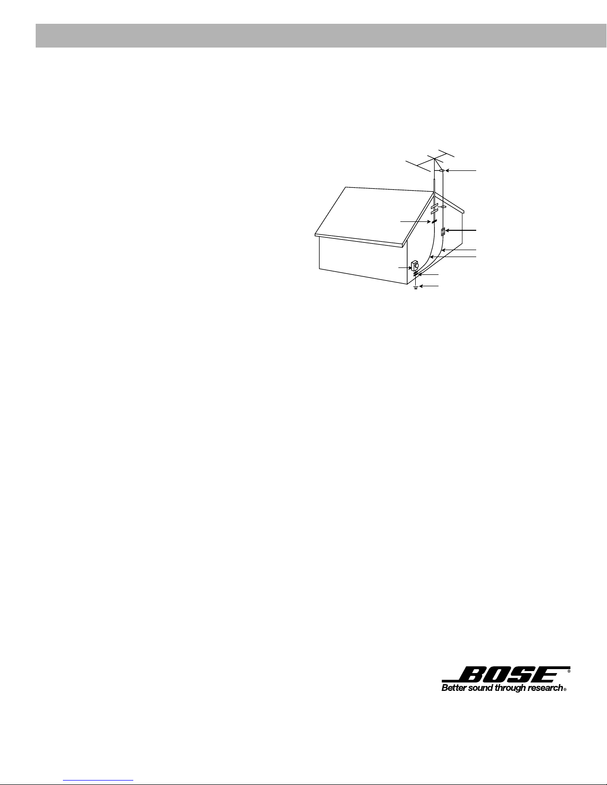
Section 810 of the National Electrical Code ANSI/
NFPA No. 70 provides information with respect to
proper grounding of the mast and supporting
structure, grounding of the lead-in wire to an antenna
discharge unit, size of grounding conductors,
location of antenna-discharge unit, connection to
grounding electrodes, and requirements for the
ground electrode. Refer to the antenna grounding
illustration on this page.
Antenna grounding
Example of antenna grounding as per National Electrical
Code, ANSI/NFPA 70.
Antenna lead in wire
Ground clamp
Electric service
equipment
Ground clamps
Power service grounding
electrode system
(NEC ART 250, Part H)
Antenna discharge unit
(NEC Section 810-20)
Grounding conductors
(NEC Section 810-21)
Note to CATV system installer
This reminder is provided to call the CATV system
installer’s attention to Article 820-40 of the NEC (of USA)
that provides guidelines for proper grounding. In particular, it specifies that the cable ground shall be connected
to the grounding system of the building, as close to the
point of cable entry as is practical.
2
b October 29, 2001 AM196575_05_V.pdf
2
©2001 Bose Corporation,
The Mountain, Framingham, MA
01701-9168 USA
255805 AM Rev.00 JN10494

Where to find…
Contents
Setting Up
Before you begin........................................................................................................... 4
Unpacking the carton ................................................................................................... 5
Selecting the locations for your Lifestyle® 25 Series II system ..................................... 6
Connecting the speakers and Lifestyle® music center.................................................. 9
Connecting your home theater components to the Lifestyle® 25 system ................... 12
Connecting the antennas ............................................................................................ 16
Installing the batteries in the remote control .............................................................. 17
Setting radio channel spacing for dual voltage and 120V systems ............................ 17
Operating Your Lifestyle® 25 System
Turning on the music center ....................................................................................... 18
The music center display ............................................................................................ 18
The music center controls .......................................................................................... 19
The Lifestyle® 25 remote control ................................................................................. 19
The system controls.................................................................................................... 20
Additional system controls ......................................................................................... 21
Listening to your Lifestyle
Operating the special features .................................................................................... 23
Chimes ........................................................................................................................ 23
Listening to digital sound............................................................................................ 24
Listening to compact discs ......................................................................................... 24
Listening to the radio .................................................................................................. 27
Using the system with external components.............................................................. 28
Maintaining Your Lifestyle® 25 System
Fine-tuning your system ............................................................................................. 29
Using two listening zones ........................................................................................... 30
Changing the house code settings ............................................................................. 32
Taking care of your Lifestyle® 25 system .................................................................... 33
Troubleshooting ..........................................................................................................34
Warranty period .......................................................................................................... 35
Customer service ........................................................................................................ 35
Product Information
Technical information.................................................................................................. 36
Accessories................................................................................................................. 36
Index .................................................................................................................................37
Bose® Corporation ....................................................................................inside back cover
®
25 system ........................................................................ 22
For your records
Serial numbers are located on the bottom of the music center and the bottom panel of the
Acoustimass® module.
Music center serial number:______________________________________________________
Acoustimass module serial number: ______________________________________________
Dealer name: __________________________________________________________________
Dealer phone: _______________________ Purchase date: ___________________________
We suggest you keep your sales slip and warranty card together with this owner’s guide.
AM196575_05_V.pdf October 29, 2001 3

Setting Up
Before you begin
Thank you for purchasing the Bose® Lifestyle® 25 Series II system. This complete audio home
entertainment system offers superb sound, elegance, technology, and simplicity for music
and home theater. Your system is fully compatible with digital program material and includes:
• A Lifestyle
• Inputs for two video sound sources, a digital sound source, and a tape deck (or other
auxiliary source)
• Capability for operating two listening zones
• Powered Acoustimass® speakers with a hideaway Acoustimass module and five cube
speaker arrays
• An easy-to-use remote control
®
music center with built-in AM/FM radio and six-disc CD changer
Realism and impact
Your Lifestyle® 25 Series II home theater system is equipped with an all new Videostage
decoder that uses digital signal processing. The result is increased surround sound realism
and impact both for movie soundtracks and music recordings. Built-in Dolby Digital decoding
of inputs from DVD, digital TV, next-generation cable boxes, and satellite receivers provides
“5.1” capability – up to five discrete audio channels directed into five independent cube
speaker arrays, plus rich bass sound from the Acoustimass module. The Videostage decoder
processes analog formats, as well as two or even single-channel PCM and Dolby Digital
bitstreams, and helps to deliver the acoustic experience of the movies right in your home.
®
Compatibility
Your system is fully compatible with:
• Digital-audio bitstreams. Look for the symbol
PCM on DVD-Video discs. Your Lifestyle® 25 Series II system cannot process MPEG-2
or DTS digital bitstreams.
• Surround-sound sources such as VCRs, stereo TVs, cable boxes and satellite
receivers. Videostage decoding directs stereo information to the surround channels, so
the sound of stereo broadcasts and rented or recorded tapes can approach that of
your DVD discs.
• Surround-encoded analog or digital audio signals. Look for the terms Surround or
Dolby Surround, or the symbol
preceding a TV broadcast.
• Stereo program material from TV, FM, CD, and cassette. Videostage decoding
delivers five channels, even when the original source contained only one or two.
• Monaural program material. Videostage decoding can process a one-channel
program into five-channel sound and direct the result to five independent speakers.
Dialogue remains locked on-screen, while music and ambient effects fill the room.
3
1
on tapes and discs, or the word “surround”
or the terms Dolby Digital or
Automatic sound level monitoring and control
Your enjoyment of movies at home is enhanced by Digital Dynamic Range® compression. This
technology automatically monitors and adjusts the volume to allow you to hear soft sounds,
particularly dialogue, and to prevent you from being overwhelmed by a loud special effect
(e.g., a crash or explosion). This feature is especially useful for late night movie viewing – it
eliminates the need for you to constantly adjust the volume level. (See pages 22-23.)
4 October 29, 2001 AM196575_05_V.pdf
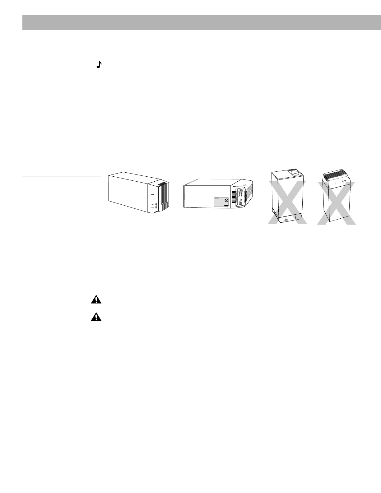
Unpacking the carton
®
T
HE
B
OSE
S
PECIAL
E
DITION
L
IFESTYLE
M
USIC
S
YSTEM
C
D
Carefully unpack your system. Save all packing materials for possible future use. The
original packing materials provide the safest way to transport your Lifestyle® 25 system. If
any part of the product appears damaged, do not attempt to use the system. Notify Bose
or your authorized Bose dealer immediately.
Check to be sure your Lifestyle
Note:
bottom of the music center. Then write them on your warranty card and in the spaces
provided on page 3.
CAUTION:
removed before turning on the system.
WARNING:
practice to avoid injury.
WARNING:
children.
Figure 1
What comes with your
Lifestyle
• Lifestyle® music center
• AC power (mains) pack*
• FM antenna
• AM loop antenna
• Antenna base
• Remote control
• 3 AA batteries
• Acoustimass module
• 5 cube speaker arrays
• AC power (mains) cord*
• Audio input cable
• 5 speaker cables
• 8 self-adhesive rubber feet
• Stereo cable
• CD magazine
• Lifestyle® system CD
• Test CD
®
25 Series II system:
(3 front and 2 surround)
AC power cord
Rubber
Setting Up
®
25 system contains the parts identified in Figure 1.
Find the serial numbers on the bottom panel of the Acoustimass® module and the
Ensure the three shipping screws on the bottom of the music center are
The Acoustimass module weighs 33 pounds (15 kg). Use good lifting
To avoid danger of suffocation, keep the plastic bags out of the reach of
Acoustimass
module
Audio input cable
AA
batteries
FM antenna
Test CD
Lifestyle
®
AC power pack
Remote control
Antenna
base
Lifestyle
®
music center
CD magazine
®
system CD
®
5 cube speaker arrays
Front speaker cables
(blue connectors)
feet
®
T
r
e
b
l
e
B
a
s
s
Surround speaker cables
(orange connectors)
Stereo cable
®
AM loop
antenna
*
Power cord and pack shown above are USA/Canada versions.
Dual voltage systems include 1 power cord, 1 adapter , and 2 power packs.
The power cords and packs for Europe, UK/Singapore, and Australia are shown below.
Europe
AM196575_05_V.pdf October 29, 2001 5
UK/Singapore
Australia

Setting Up
Selecting the locations for your Lifestyle® 25 Series II system
When you place your speakers according to the guidelines below, a combination of reflected
and direct sound provides the audio atmosphere of a home theater. You may experiment with
the placement and orientation of the cubes to produce the sound most pleasing to you. For
more discussion of speaker placement and room acoustics, see “Fine-tuning your system”
on page 29.
Speaker locations
Follow these guidelines to select locations that provide the maximum home theater effect
from your Lifestyle® 25 system (Figures 2 and 3).
CAUTION:
cube speakers to move, particularly on smooth surfaces like marble, glass, or highly polished
wood. If you are placing the center speaker on top of the television, use the smaller of the two
sets of rubber feet provided. You may obtain additional rubber feet (part no. 178321), free of
charge, by contacting Bose® Customer Service (see listings on the inside back cover).
Left and right front speakers
The sound from the left and right front speakers should seem to appear at the edge of the
picture, so that the acoustic image is close to the size of the visual image (Figure 2).
1. Place the cubes so that they line up with the center of the TV screen.
2. Place them up to 3 feet (1 m) from the edge of the TV screen.
We recommend a maximum distance of 3 feet (1 m) so that the sound does not become
too separated from the picture. You may wish to vary this distance based on room conditions and personal preference. The front cables allow the cube speakers to be placed up
to 20 feet (6.1 m) from the Acoustimass module.
3. Direct one cube of each array forward. Direct the other cube toward the wall or in a
different direction to create reflected sound. (See the illustration of reflected sound patterns in Figure 3.)
Note:
TV without affecting picture quality.
Choose a stable and level surface for your speakers. Vibration can cause the
The cube speakers are magnetically shielded so you can place them close to the
Center speaker
The sound from the center speaker should appear to come directly from the center of the
picture (Figure 2). The center speaker cable allows up to 20 feet (6.1 m) distance from the
Acoustimass module.
1. Place the center speaker directly above or below the center of the TV screen, or at the
closest convenient location.
2. Align the speaker with the front of the TV screen (not pushed to the back of the TV).
3. Direct each of the cubes slightly away from center, to create a wider area of direct sound
(Figure 3).
Note:
If you put the speakers in a bookcase unit, be sure to place each one at the front
edge of the shelf. Placing speakers in an enclosed space can change the tonal quality of the
sound. This effect is minimized if the shelves are filled with books.
6 October 29, 2001 AM196575_05_V.pdf
Setting Up
Figure 2
Recommended front speaker
locations
Figure 3
Speaker placement
Center
Left front
®
Right front
Surround speakers
The surround (rear) speakers create an area of sound around the listener. Place them in the
back half of your room. Direct the cubes so that you cannot pinpoint the exact location of the
sound source (Figure 3). The surround cables allow up to 50 feet (15.2 m) distance from the
Acoustimass® module.
Left
front
Center
Right
front
Acoustimass
module
Left
surround
Right
surround
1. Place the speakers at ear height or higher, if possible.
2. Adjust the rear surround speakers to direct the sound to the front and back of the listener.
AM196575_05_V.pdf October 29, 2001 7
Setting Up
Figure 4
Acoustimass module positions
Acoustimass® module
Follow these guidelines to select a location for the Acoustimass module.
Note:
18 inches (45 cm) from the TV.
1. Place the Acoustimass module along the same wall as the TV, or close to the same end of
2. Select a convenient location – under a table, behind a sofa. Do not allow furniture or
3. Place the Acoustimass module within reach of the audio input cable, speaker cables, and
4. Select a position for the Acoustimass module (Figure 4). For proper ventilation, place it on
To avoid interference with the TV picture, place the Acoustimass module at least
the room as the front speakers (see the example along the front wall in Figure 3).
drapes to block the ventilation openings of the module.
an AC power (mains) outlet.
the long edge, with the connectors facing the floor. An alternate position is on its largest
side, with the bass and treble controls facing up. Do not place the module on either end,
as shown by the last two views in Figure 4.
®
R
I
G
H
T
R
I
G
H
T
F
R
O
N
T
R
E
A
Preferred
position
®
T
r
e
b
l
e
B
a
s
s
Alternate position
®
R
L
E
F
T
C
R
E
E
N
A
T
R
E
R
L
E
F
T
F
R
O
N
T
O
U
T
P
U
T
S
T
O
C
U
B
E
S
P
E
A
K
E
R
S
®®
5. Once you have selected a position for the module, place the four self-adhesive rubber feet
near the corners of the bottom surface. The rubber feet provide increased stability and
protection from scratches.
6. Aim the port (the round opening) into the room or along the wall to avoid blocking the port
or creating too much bass.
7. For best bass performance, do not place the port at equal distances from any two walls or
from a wall and the ceiling.
CAUTION:
Do not cover the ventilation openings of the Acoustimass module. The slots on
the end provide ventilation for the built-in electronic circuitry, and should not be blocked.
CAUTION:
The magnetic field from the Acoustimass module is not an immediate risk to your
video tapes, audio tapes, and other magnetic media. However, you should not store tapes
directly on or near the Acoustimass module.
Music center
Select a location for the music center.
1. Allow enough room to open the CD player cover.
2. Place the music center close enough to the sound sources (TV, VCR, DVD player etc.) to
allow for cable length. If you need additional audio and/or video cables to connect all of
your components, see your dealer or call Bose®.
3. Place the music center within 30 feet (9.1 m) of the Acoustimass module (the length of the
audio input cable).
8 October 29, 2001 AM196575_05_V.pdf
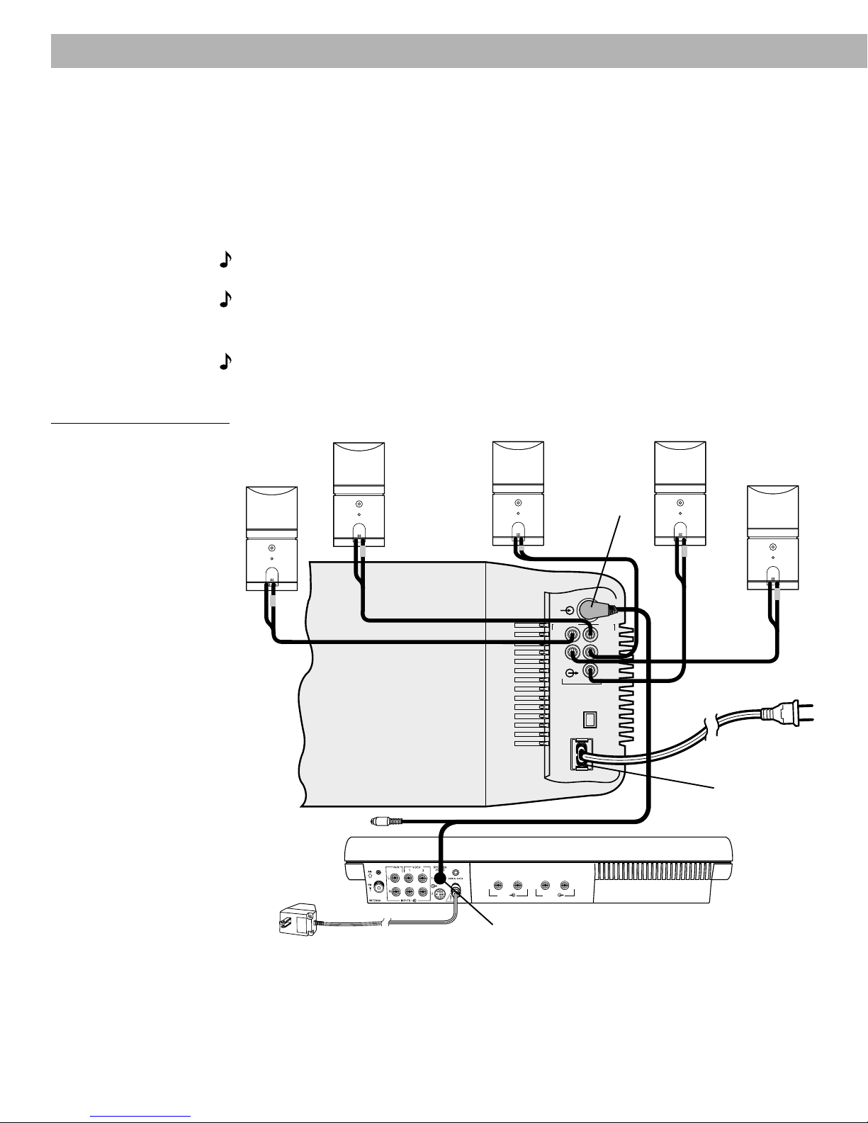
Connecting the speakers and Lifestyle® music center
Once you have selected locations for your music system, connect the speakers.
CAUTION:
begin hooking up the system.
Connecting the cube speaker arrays to the Acoustimass
module
Each speaker cable contains two wires. The wire marked with a red collar is positive (+) and
the plain one is negative (–). These wires match the positive (red) and negative (black) terminals on the back of each speaker. To lengthen the cable, use heavy-duty RCA extension
cables or splice in 18-gauge or thicker cord (connecting + to + and – to –). To purchase
cables, see your dealer or electronics store, or call Bose® customer service.
Note:
use cable for connecting the surround speakers. To run the cables in different directions from
the Acoustimass module, simply pull apart the cables as needed.
1. Match the correct cable to the corresponding speaker location.
• Front speaker cables have blue connectors at one end, with L, R, or C molded into the
• Surround speaker cables have orange connectors at one end, with L or R molded into
2. Connect the wire end of one speaker cable to the terminals on the rear of the matching
cube speaker array.
a. Press the terminal tab on the back of the cube array to insert the marked wire into the
b. Repeat this step for each of the five cube speaker arrays. (See Figure 5.)
Make sure all components are unplugged from the power outlet before you
The surround cables are joined together for your convenience, providing an easy-to-
connectors. The red collars on the + wire are labeled LEFT, RIGHT, and CENTER.
the connectors. The red collars on the + wire are labeled LEFT and RIGHT.
red terminal and the plain wire into the black terminal. Release the tab to secure the
wire.
Setting Up
®
Figure 5
Speaker cable connections to
the cube speaker array
CAUTION:
Make sure no strands of wire from any terminal touch any other terminal.
Bridged wires create short circuits that affect proper operation of your system.
3. Connect each cable to the corresponding jack on the Acoustimass module.
a. Plug the blue connectors into the matching left front, center, and right front jacks.
b. Plug the orange connectors into the matching left surround and right surround jacks.
AM196575_05_V.pdf October 29, 2001 9
Setting Up
Connecting the Acoustimass® module to the Lifestyle® music
center
Connect the Acoustimass module to the music center with the audio input cable (Figure 6).
1. Plug the small black multi-pin connector (flat side facing up) into the jack marked
SPEAKER ZONE 1 on the rear of the music center.
2. Insert the single right-angle multi-pin connector on the other end of the audio input cable
into the AUDIO INPUT jack on the Acoustimass module. Align the connector at the angle
shown in Figure 6.
Note:
your home theater components...” on page 12.
Note:
3. Extend the audio input cable as much as possible, since it includes an antenna for the
Note:
second zone.
Connect your digital signal source to the female RCA connector. See “Connecting
Be sure that each connector is fully inserted into each jack.
remote control.
Refer to “Using two listening zones” on page 30 for information on connecting a
Figure 6
Music center and speaker
connections
Right
surround
speaker
To digital signal
source
Right front
speaker
Center
speaker
AUDIO
INPUT
RIGHT
LEFT
OUTPUTS TO
CUBE SPEAKERS
Right-angle
connector
into AUDIO
INPUT
FRONTSURROUND
RIGHT
CENTER
LEFT
Left front
speaker
Left
surround
speaker
Audio
input
cable
AC power jack
10 October 29, 2001 AM196575_05_V.pdf
AC power pack
LR
TAPE IN
LR
TAPE OUT
Multi-pin connector into SPEAKER ZONE 1
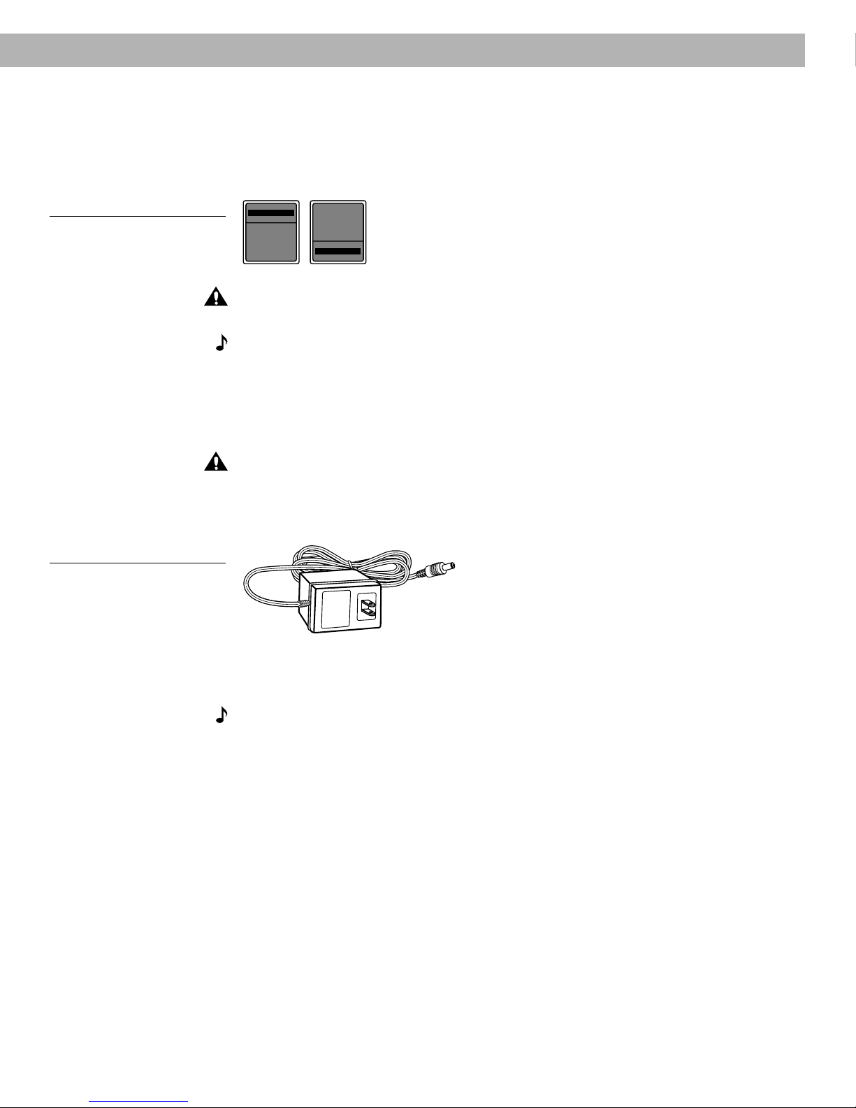
Figure 7
Dual voltage Acoustimass
module: voltage selector switch
settings
Setting Up
Connecting the Acoustimass® module power (mains) cord
1. On a dual voltage system, the voltage selector switch is preset at the factory to be correct
for your area. Check to be sure it is set for the proper voltage (Figure 7). Use 115V for
North America; 230V for Europe and Australia. In Europe, use the adapter plug provided. If
you are in doubt, contact your local electric utility for the appropriate voltage setting.
230 V
115 V
Figure 8
The AC power pack
(model PS71 shown)
CAUTION:
2. Plug the small end of the power (mains) cord into the Acoustimass module AC power jack.
Note:
Make sure the voltage selector switch is set correctly.
Do
not
plug the AC power cord into a power outlet until all component connections
are complete.
Connecting the music center AC (mains) power pack
The Lifestyle® music center comes with a 120V AC (mains) power pack for use in the USA
and Canada or an appropriate 230V or 240V power pack for international use. (See Figures 1
and 8.) Dual voltage models include both 120V and 230V power packs.
CAUTION:
Be sure to use the correct power pack for your area. Using the wrong one may
damage your power pack or your music center.
• Model PS71, 120V in North America • Model PS72, 230V in Europe
• Model PS74, 230V in UK or Singapore • Model PS77, 240V in Australia
1. Firmly insert the small connector on the end of the AC (mains) power pack cable into the
AC POWER jack on the back of the Lifestyle® music center.
2. Make sure that the power pack reaches an AC (mains) outlet.
Note:
Do
not
plug the AC power pack into a power outlet until all component connections
are complete.
AM196575_05_V.pdf October 29, 2001 11
 Loading...