

Bose Entero 440, Entero 4100, Entero 4400, Entero 840, Entero 4200 Installation & Operation Manual

Bose®Entero®440/840/4100/4200/4400 multi-channel power amplifier
Installation & operations manual
Installationsvejledning
Installationsanleitung
Guía del instalador
Manuel de l’installateur
Guida all’installazione
Installatiehandleiding
Installationshandbok

The manufacturer reserves specification privileges. Information in this manual is subject to change without prior notice or obligation.
Der Hersteller behält sich das Recht vor, Änderungen im Sinne des technischen Fortschritts durchzuführen, die u.U. noch nicht in dieser
Bedienungsanleitung berücksichtigt wurden.

3
1. Important Safety Instructions 4
2. Declarations of Conformity 5
3. Caution 5
4. Getting Started 6
4.1 Unpacking
4.2 Installation
4.3 Panel Front View
5. Rear Panel Connections 7
5.1 Entero
®
440 (four channel version) and 840 (eight channel version)
5.2 Entero 4100, 4200, 4400
6. Air Ventilation and Cooling Requirements 8
7. AC Power Connection 8
8. Power Switching / Remote On/Off-Switching 9
9. Front Indicators and Control 10
10. Audio Input Connections 11
10.1 Balanced and unbalanced Inputs, Levels
10.2 Input Level Controls
10.3 Grounding
10.4 Decibel Explanation
10.5 Equalisation
11. Loudspeaker Output Connections 13
11.1 Output Wiring
11.2 Output Connectors
11.3 100 Volt Systems
12. Operation Modes 14
12.1 Stereo Operation
12.2 Parallel Operation
12.3 Bridged Operation
13. Noise Gate Option 15
14. Technical Data 16
15. Troubleshooting 17
16. Warranty Period 18
17. Service 18
Table of Contents
English Dansk Deutsch Español Français
Italiano
Nederlands
Svenska
1. Important Safety Instructions
English
1. Important safety instructions
WARNING: These units are electrical appliances. To reduce the risk of fire or electric shock, do not expose
them to rain or moisture; do not disassemble the unit.There are no user-serviceable parts inside. Refer
servicing to qualified service personnel.
The lightning flash with arrowhead symbol, within an equilateral triangle, signifies the
presence of uninsulated dangerous voltage within the system enclosure that may be of
sufficient magnitude to constitute a risk of electrical shock.
The exclamation point, within an equilateral triangle, as marked on the system, signifies the
presence of important operating and maintenance instructions in this guide.
1. Read, Follow, and Save All Instructions – Read the complete safety and operating instructions for all
components before using this product. Follow all instructions. Save the instructions for future reference.
2. Pay Attention to Warnings – Observe all warnings on the product and in this guide.
3. Do Not Use Near Water or Moisture – Do not use this product near a bathtub, washbowl, kitchen sink,
laundry tub, in a wet basement, near a swimming pool, or anywhere else that water or moisture is present.
4. Cleaning – Unplug system units from the mains outlet before cleaning. Do not use liquid cleaners or
aerosol cleaners. Use a damp cloth for cleaning.
5. Object and Liquid Entry – Never push objects of any kind into this unit through openings as they may
touch dangerous voltage points or short-out parts that could result in a fire or electric shock. Never spill
liquid of any kind on the unit.
6. Attachments – Do not use attachments not recommended by Bose®Corporation as they may cause
hazards.
7. Maintain Proper Ventilation – To ensure reliable operation of the product and to protect it from
overheating, put the product in a position and location that will not interfere with its proper ventilation. Do
not put it in a built-in system, such as a bookcase or a cabinet, that may keep air from flowing through its
ventilation openings.
8. Use Proper Power Sources – Plug the product into a proper power source, as described in the operating
instructions or as marked on the product. If you are not sure of the type of power supply you plan to use,
consult your appliance dealer or local power company.
9. Avoid Overloading – To prevent the risk of fire or electric shock, do not overload wall outlets, extension
cords, or integral convenience receptacles.
10. Be Careful with Accessories – Mount the product only as recommended by Bose Corporation. Do not
put this product on an unstable cart, stand, tripod, bracket, or table. The product may fall, causing serious
injury to a person or damage to the product. For advice on use of a particular cart, stand,
tripod, bracket, or table, contact Bose Corporation.
If you must move your product and cart combination, do so very carefully. Quick stops,
excessive force, and uneven surfaces may cause it to overturn.
4

English
11. Protect the Power Cord – Route all power supply (mains) cords so that they are not likely to be
walked on or pinched. Pay particular attention to cords at plugs, at outlets on the product, and at the
point where the cord connects to the product.
12. Take Precautions against Lightning and Power Line Surges – To prevent damage to this product
during a lightning storm, or if the product will not be used for an extended period of time, unplug its
power cord from the wall outlet and disconnect the antenna or cable system.
13. Do not defeat the safety purpose of the polarized or grounding-type plug – A polarized plug has
two blades with one wider than the other. A grounding-type plug has two blades and a third grounding
prong. The wide blade or the third prong are provided for your safety. When the provided plug does not
fit into your outlet, consult an electrician for replacement of the obsolete outlet.
14. Servicing – Do not attempt to service this unit yourself as opening or removing covers may expose to
dangerous voltage or other hazards. Refer all servicing to qualified service personnel.
15. Obtain Service When It Is Indicated – Unplug the unit from the outlet.The product should be serviced
only by authorised service personnel when:
A. the power supply cord or the plug has been damaged, or
B. objects have fallen or liquid has spilled into the product, or
C. the product has been exposed to rain or water, or
D. the product does not appear to operate normally or exhibits a marked change in performance. Adjust
only those controls which are covered by the instructions for use, as an improper adjustment of other
controls may result in damage and will often require extensive work by a qualified technician to restore
the units to their normal operation, or
E. the product has been dropped or the cabinet damaged.
2. Declarations of Conformity
The manufacturer of this amplifier hereby declares that this product is in accordance with the following
standards:
EMC Regulation 89/336/EEC (Electromagnetic Compatibility)
EN-55103-1
EN-55103-2
IEC 60065 6thEdition
3. Caution
To reduce the risk of electrical shock, do not remove the cover. There are no user serviceable parts inside,
refer all servicing to qualified personnel. If opened by qualified personnel, disconnect the amplifier
completely from the main power. Replace fuses only with same type. Avoid damaging the AC plug or
cord. It can potentially causing a shock hazard.The unit should only be connected to an AC power supply
of the correct voltage. Damage caused by incorrect power voltage is not covered by warranty.
To reduce the risk of fire or electrical shock, do not expose this appliance to rain or moisture. Do not use
this unit in damp areas or near water.
The amplifier must be adapted slowly to extreme temperature changes. These extreme changes can
cause moisture development inside the amplifier that can cause failure and/or electrical shock.
5
2. Declarations of Conformity
4. Getting Started
English
Though the Entero®amplifiers are quite simple to operate and are covered by a solid steel chassis,
improper use can be dangerous.The amplifiers can put out very high voltages and a sizable current at
frequencies up to 30kHz.
NEVER isolate the ground of the AC power cord (the non-fused earthed protective conductor) to
eliminate hum-problems. See chapter ‘Grounding’ too.
Always use safe operating techniques! Incompetent and improper servicing can void the warranty.
4. Getting Started
4.1 Unpacking
Upon unpacking, please inspect the amplifier. If you find any damage, notify your supplier immediately.
Be sure to save the carton and all packing materials in case you have to send the product to the supplier.
Please use only the original factory packing. If the shipment carton is unavailable, contact your local
dealer to obtain a replacement unit.
4.2 Installation
The amplifiers will mount in standard 19-inch racks having sufficient depth. For the installation 4 metric
M6 bolts should be used. It is recommended using all four front mounting holes to properly secure the
power amplifier in the rack and use a stable installation support at the rear of the amplifier to avoid
torsion at the front panel.
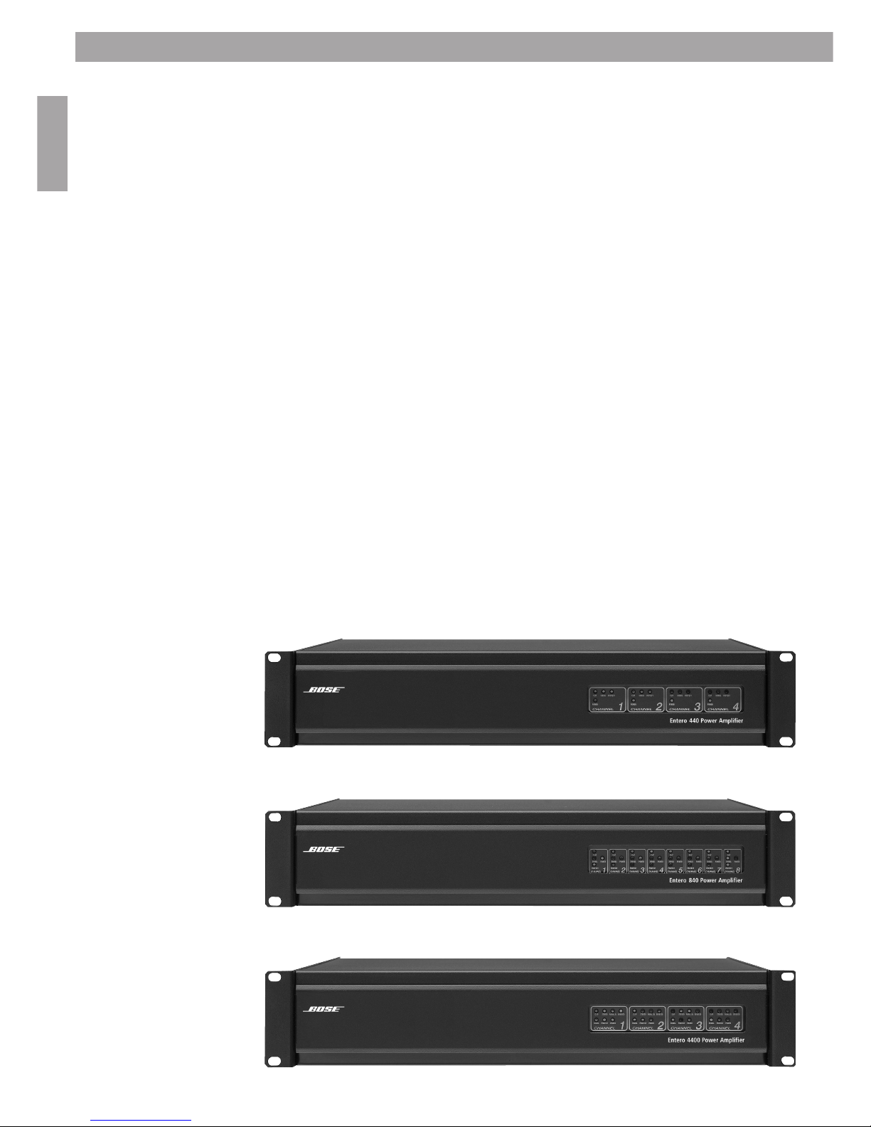
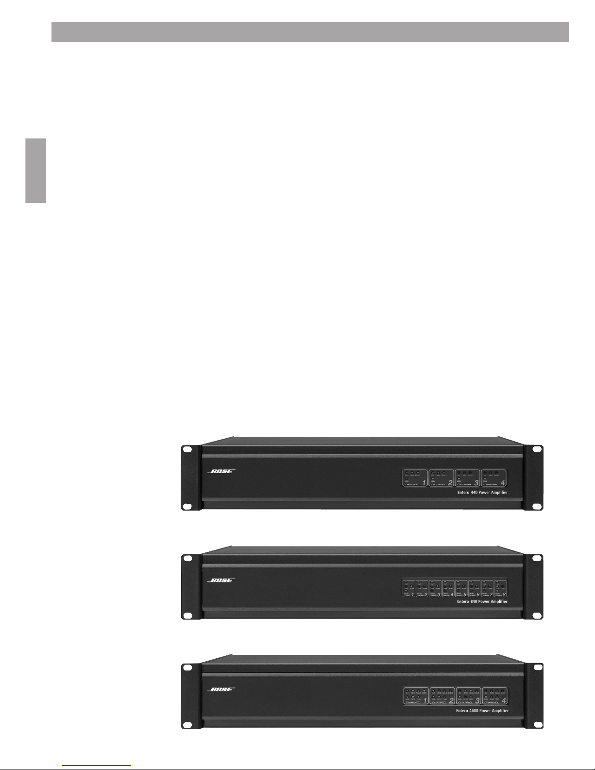
4.3 Panel Front View
Bose Entero 440:
Bose Entero 840:
Bose Entero 4100, 4200, 4400:
6
English
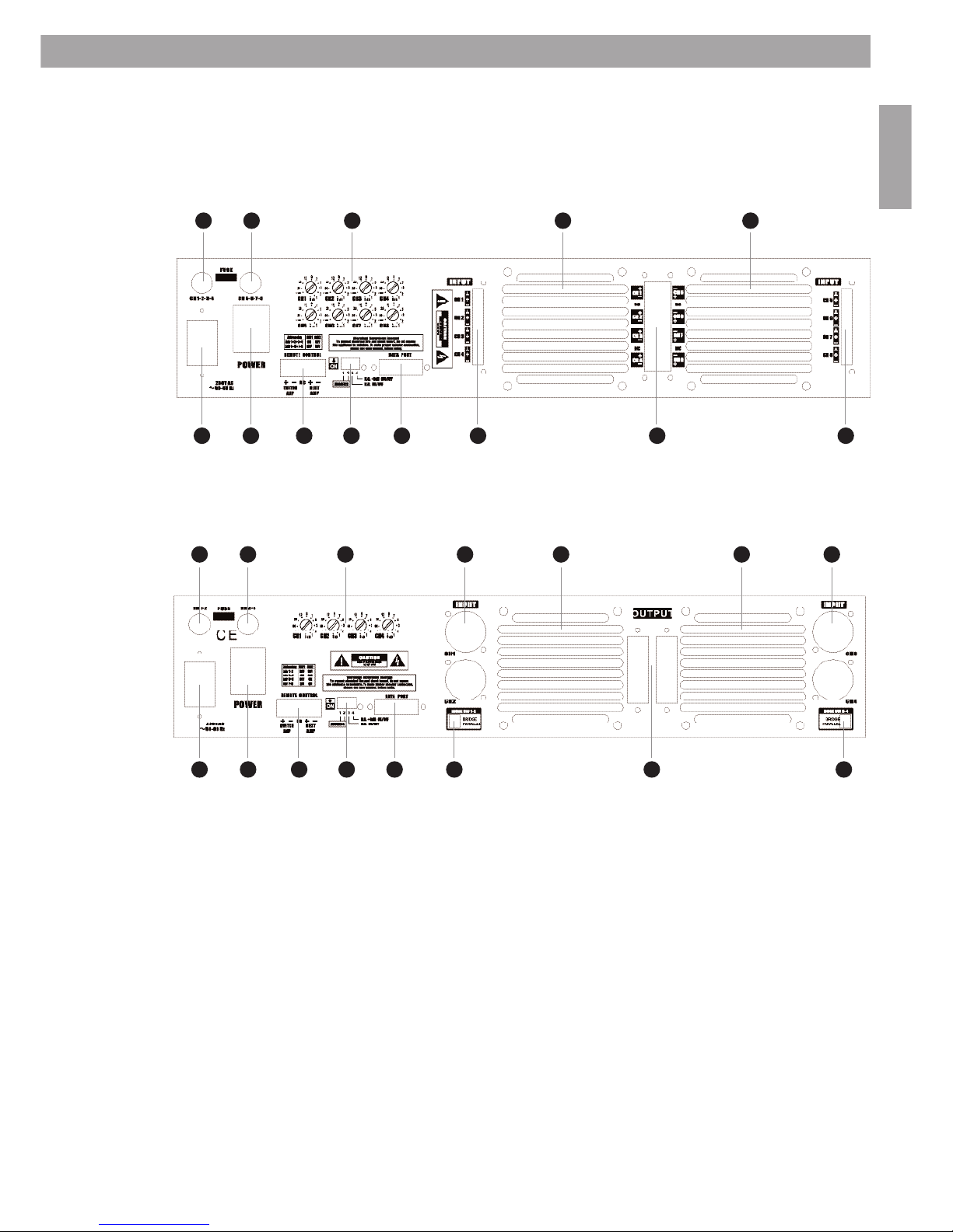
5. Rear Panel Connections
Entero®440 (four channel version) and 840 (eight channel version)
Entero 4100/4200/4400
Legend
1. Power Connector
2. Main Power Switch
3. Fuse Power Supply 1
4. Fuse Power Supply 2
5. Remote Power Switch Connector
6. DIP Switch for Channel Address and Noise Gate
7. Sub-D Connector for Future Control Connection
8. Phoenix Input Connectors
9. Phoenix Input Connectors (Entero 840 only)
10. XLR / TRS Input Connector, Channel 1 and 2
11. XLR / TRS Input Connector, Channel 3 and 4
12. Phoenix Output Connector, Channel 1 to 4 (and 5 to 8, Entero 840 only)
13. Level Control, Channel 1 to 4 (and 5 to 8, Entero 840 only)
14. Cooling / Fan
15. Cooling / Fan
16. DIP Switch for Stereo, Parallel and Bridge Mode, Channel 1 and 2
17. DIP Switch for Stereo, Parallel and Bridge Mode, Channel 3 and 4
7
3
1 2 5 6 7 9 12 8
4 14 1513
5. Rear Panel Connections
3 10 11
1 2 5 6 7 16 12 17
4 14 1513
6. Air Ventilation and Cooling Requirements
English
6. Air Ventilation and Cooling Requirements
The amplifier is equipped with a forced air-cooling system with variable speed and temperature
controlled fans to guarantee low operating temperature and minimal ventilation noise.The air flow
takes place from the front of the amplifier to the rear.
In case any heat sink becomes too hot, the temperature sensor opens the respective output relay,
disconnecting the output load from the particular channel. In case the power transformer gets
overheated, a different sensor causes the output relays on all channels to open and to interrupt the
outputs.After cooling down to the appropriate operating temperature the relay contacts are closed
again automatically.
It is important to have adequate air ventilation space behind the amplifier to allow a proper air flow.
In case the amplifier is mounted into a closed rack, do not cover the front of the rack with doors. When
using racks with a closed backside, use fans on the rear rack panel (air flow to the inside of the rack).
For larger installations in rooms with insufficient ventilation or at temperatures above 25°C, we
recommend use of ventilation plates (1RU) between the amplifiers.
At room temperatures above 30°C we recommend use of airconditioning
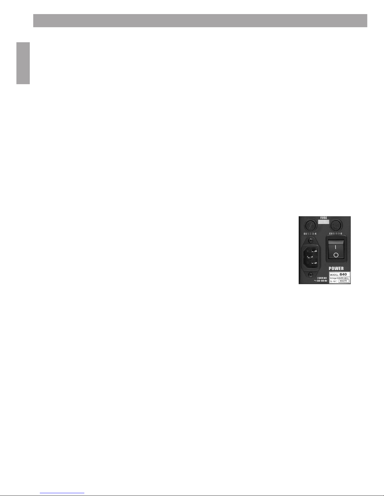
7. AC Power Connection
The power amplifier must be connected only with the supplied three-wire safety
power cord with protective conductor (non-fused earthed conductor). Check for
the proper mains voltage before connecting the power cord. Damages caused
by wrong supplied power voltage will not be covered by warranty.
Always turn off and disconnect the amplifier from the mains voltage before
making any audio connections.
The power fuses are located on the back panel of the amplifier and can be
accessed from the outside. Use only the appropriate fuses as labeled.
After properly mounting and connecting the AC cord and the audio connections,
the unit can be switched on.
Number of separate power transformers integrated in the power supply of the different models:
Bose®Entero®440: 1 power transformers (4 channels per transformer)
Bose Entero 840: 2 power transformers (4 channels per transformer)
Bose Entero 4100: 2 power transformers (2 channels per transformer)
Bose Entero 4200: 2 power transformers (2 channels per transformer)
Bose Entero 4400: 2 power transformers (2 channels per transformer)
The POWER indication LED indicates that the amplifier has been turned on. The PROTECT - LED
will also light up and indicate active protection relays.This LED will turn off after about 2 seconds.
8

English
8. Power Switching / Remote On/Off-Switching
There are two options to switch the amplifier on and off.
Option 1 – Local Switching:
A power switch is located at the rear panel of the amplifier. This switch is connected as a regular power
switch with plain on/off switching. If the unit is switched on with this power switch, the remote
switching options are disabled. For remote switching options, the regular power switch should be always
in the OFF-position.
Option 2 – Remote Switching with 12 VDC-Control Voltage:
The PHOENIX terminal connection is used for remote switching with control voltage (DC).Terminal 1 and
2 are used as control voltage input. Supplying the control voltage to these terminals will switch the
amplifier ON.Additionally the terminals 4 and 5 will be fed with the control voltage after a delay of one
second. These terminals can be connected to the terminals 1 and 2 of the next amplifier for sequential
switching. Up to 20 units can be daisy-chained this way for sequential switching of the entire group of
amplifiers.
The control voltage doesn’t need to be supplied continuously, only a short impulse is necessary to initiate
the switching-on procedure of the amplifier, but the control voltage must be supplied until the last
amplifier in the daisy-chain setup is switched on.
By supplying the inverted DC control voltage to terminal 1 and 2, the amplifier will be switched off. As for
the switching-on procedure, this control voltage will be fed to the terminals 4 and 5 as supply of the
control voltage for the next daisy-chained amplifier. For the switching-off sequence, no delay is engaged.
All amplifiers are switched of at the same moment.
As long as no control voltage is fed to the terminals 1 and 2, the amplifier will stay in the actual state
(on or off).
Remote Switching PHOENIX Connector:
1 – Amplifier Switching POSITIVE terminal
2 – Amplifier Switching NEGATIVE terminal
3 – not connected
4 – Control Voltage supply for sequential switching of
next amp POSITIVE terminal
5 – Control Voltage supply for sequential switching of
next amp NEGATIVE terminal
Control Voltage: 12 VDC / 40mA per amplifier.
9
8. Power Switching / Remote on/Off-Switching
1 2 3 4 5

9. Front Indicators and Control
English
9. Front Indicators and Control
The amplifier is not equipped with any kind of manual level control knobs at the front panel of the
amplifier.
LED Indicators
4 resp. 7 LEDs for each amplifier channel: CLIP, SIGNAL,
PROTECT and POWER,additional three LEDs to indicate
the amplifier mode (Entero®4100, 4200 and 4400 only).
Entero 440/840 Entero 4100/4200/4400
LED COLOR FUNCTION
POWER Blue Indicates, that the amplifier is powered up.
CLIP Red Indicates, that the input is overloaded.
The LED starts illuminating as soon as the signal is 0,5 dB under full power.
SIGNAL Green Indicates, that signal reaches the output stage of the amplifier.
PROTECT Red This LED will light up as soon a protection circuit has been activated or if one of the
output relays has been activated. When the amplifier is switched on, this LED
illuminated for approximately 1.5 seconds.
MODE Amber Three amber LEDs indicate, which mode (Stereo, Parallel, Bridge) is selected
(Entero 4100/4200/4400 only!)
10
English
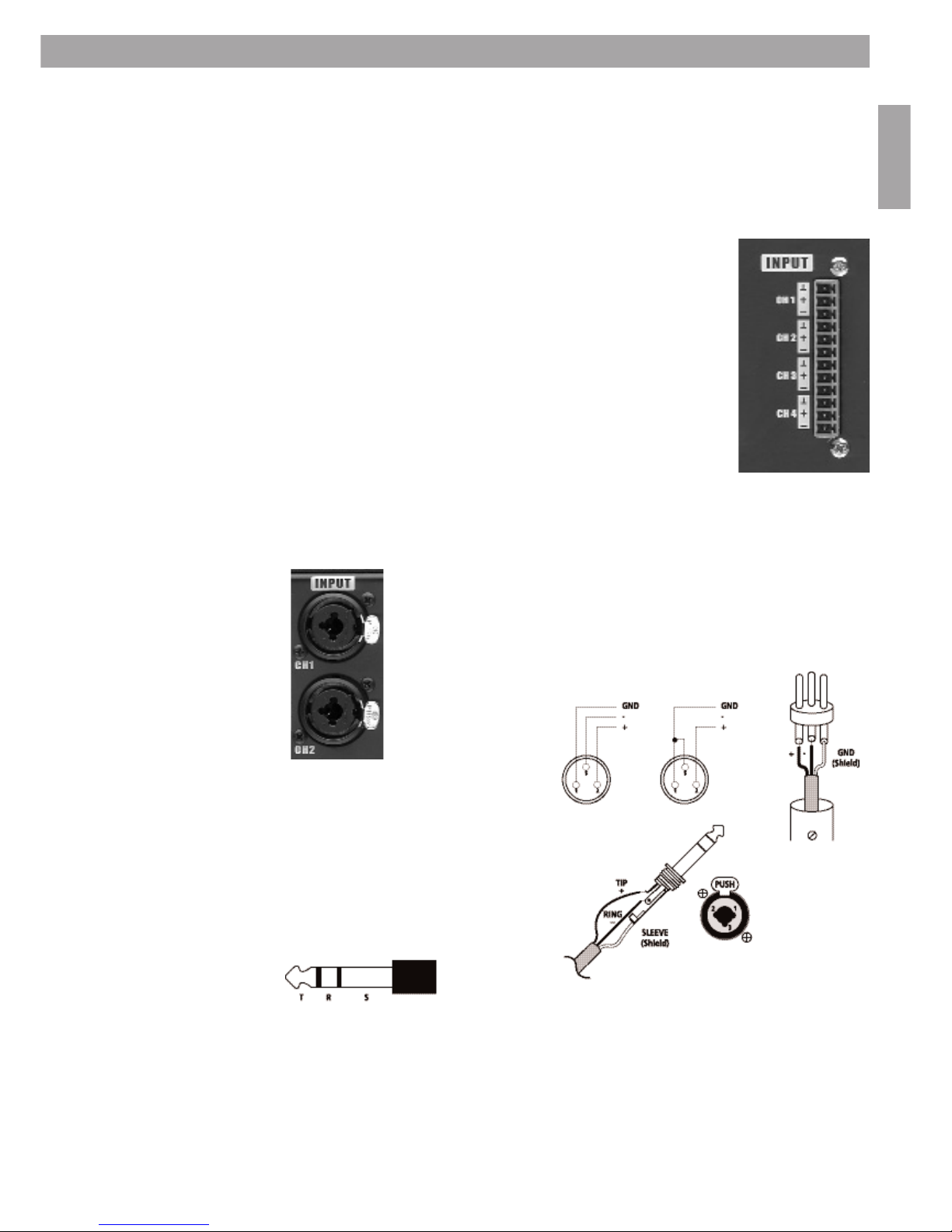
10.Audio Input Connections
Always turn off the amplifier before making audio connections!
Entero®440/840:
The Entero 440 and 840 are equipped with 12-pin PHOENIX input connectors.
PHOENIX input connector channel 1 to 4:
Pin 1: ground, channel 1
Pin 2: signal positive, channel 1
Pin 3: signal negative, channel 1
Pin 4: ground, channel 2
Pin 5: signal positive, channel 2
Pin 6: signal negative, channel 2
Pin 7: ground, channel 3
Pin 8: signal positive, channel 3
Pin 9: signal negative, channel 3
Pin 10: ground, channel 4
Pin 11: signal positive, channel 4
Pin 12: signal negative, channel 4
Entero 840 is equipped with two 12-pin PHOENIX connectors
for channel 1 to 4 and channel 5 to 8 respectively.
Entero 4100/4200/4400:
The Entero 4100, 4200 and 4400 power amplifier models are equipped with four
combined XLR/TRS input connectors.The combined connectors can be used for
regular XLR connectors and for 6,3 mm TRS jacks, mounted in the same connector
chassis.The audio inputs are electronically balanced. For XLR-connection, use a
male connector.
Standard pinout for XLR connectors:
1 = Ground, Shield
2 = Signal Positive
3 = Signal Negative
Standard pinout for the 6,3 mm TRS-jack:
Tip = Signal Positive
Ring = Signal Negative
Sleeve = Ground, Shield
11
10. Audio Input Connections

10. Audio Input Connections
English
10.1 Balanced and unbalanced Inputs, Levels
The amplifier can accept unbalanced or balanced lines. For optimum performance and with longer cable
runs, use balanced lines whenever possible.The driving device should be equipped with a balanced
output. With short cables inside one rack the issue is not that critical.
A balanced connection provides excellent noise immunity from interference and ground loops.A balanced
audio connection is accomplished by using a differential pair of signals, isolating them from ground.
While these connections provide great noise immunity, care must be used when connecting balanced and
unbalanced equipment together.
10.2 Input Level Controls
All models are equipped with rotary level controls for each channel at the rear side of the amplifier. The
level control knobs are digital rotary dip controllers with 16 dedicated steps.The values are indicated on
the rear panel.
10.3 Grounding
The chassis ground of the amplifier is connected with the ground of the AC power cord (the non-fused
earthed protective conductor). As soon as several devices are connected with each other in a signal
chain, a ground loop is created. Ground loops are caused when current flows from the analog ground
plane of one piece of equipment to the ground plane of another. A compensating current travels between
the different devices on the shields of the audio cables.This is mostly causing hum-problems.
Using a proper cabling, ground loops should be avoided.
NEVER isolate the ground of the AC power cord (the non-fused earthed protective conductor) to
eliminate hum-problems.This is a violation of the law and dangerous !
10.4 Decibel Explanation
A decibel is a logarithmic scale commonly used to express differences in signal levels. It is useful in audio
because it can express a wide dynamic range with relatively small numbers (or a small movement on a
meter), and it more closely matches how we perceive sound.
The measurement quoted in dB describes the ratio between the quantity of two levels, the level being
measured and a reference.The absolute quantity of the signal is not relevant. This means that decibels
are always comparing one quantity to another. For example, when we measure gain in dB, we are
comparing the output level to the input level.
To describe an absolute value, the reference point must be known. There are different reference points
defined.
dBV represents the level compared to 1 Volt RMS. 0dBV = 1 Volt with no reference to impedance.
dBu represents the level compared to 0,775 Volt RMS on an unloaded, open circuit.
dBm represents the power level compared to 1 mWatt.This is a level compared to 0,775 Volt RMS across
a 600 Ohm load impedance.
1dBV equals +2.2dBu, +4dBu equal 1.23 Volt RMS, the reference level of -10dBV is the equivalent to a
level of -7.8dBu.
Headroom is a measure (usually in dB) of how much higher the peaks of a signal can be compared to the
nominal level without clipping. That is, it compares the peak level (in volts RMS) to the nominal level (in
volts RMS). The difference between the two (in dB) is the headroom.
12

English
10.5 Equalisation
For use with active equalised Bose®loudspeakers, please use the Panaray®System Digital Controller or the
appropriate EQ cards.The EQ cards must be EQ card series II-s. To install the cards, the amplifier must be
opened. For instructions, please refer to the EQ card manual which comes with the card.
11.Loudspeaker Output Connections
The impedance of the connected loudspeaker line could be between 2 Ohm and 16 Ohm. The minimal
connected loudspeaker impedance is 2 Ohm. In BRIDGE operation mode the minimal connected
impedance must be 4 Ohm.
11.1 Output wiring
Use heavy gauge wire for speaker connections. The greater the distance between the amplifier and the
speakers, the larger the diameter the wire should be.This will minimize power losses across the wire and
improve damping of the speaker. Wire thickness specifications (gauges) get larger as the wire gets
thinner. So a 14-gauge wire is thicker than 18-gauge wire.
11.2 Output Connectors
The Loudspeaker cables should be connected to the PHOENIX output connectors. Channel numbers and
the polarity are labeled on the connectors.
11.3 100 Volt Systems
For 100 Volt applications, the speaker output connections may be connected to a transformer package
Trapack 2 or Trapack 4. See table below.
TRAPACK 2 TRAPACK 4
Entero
®
440
Entero 840 Yes N o
Entero 4100
Entero 4200
No Yes
Entero 4400
13
11. Loudspeaker Output Connections

12. Operation Modes
English
12.Operation Modes
On the rear of the amplifier you’ll find two mode-select DIP switches with each two single switches for
the operation modes PARALLEL and BRIDGE (Entero®4100, 4200 and 4400 only). In case both single
switches are OFF, the amplifier channels are in the regular STEREO mode.
12.1 Stereo Operation
In the Stereo operation mode, each channel will work independently from each other. Input connector 1
will generate signal on output connector 1 and so on.
If EQ cards are required, see chapter 10.5; each channel needs its own EQ card.
12.2 Parallel Operation
Entero®440/840
Both inputs of the channel pair must be fed with the same signal by connecting the input cable parallel
to both input connectors.
If EQ cards are required, see chapter 10.5; each channel needs its own EQ card.
Entero 4100/4200/4400
For parallel operation, turn the amplifier off and set the mode select switch of the chosen power
amplifier pair to the PARALLEL position. Both channels are then driven by the signal connected to the
first channel of the pair (channel 1 and 2 by input 1, channel 3 and 4 by input 3).
Only the inputs of channel 1 and 3 are active, channels 2 and 4 are out of circuit.
If EQ cards are required, see chapter 10.5; only channel 1 and 3 need their own EQ card.
12.3 Bridged Operation
Channels can be used in BRIDGE mode. Channel 1 and 2 and channel 3and 4 can be used as an
independent channel pair.
Entero 440/840
Switch the amplifier off.The input signal should be wired to the first channel of the channel pair in the
regular mode and wired to the second channel in inverse mode (the positive pole to the negative pin and
the negative pole to the positive pin).
The amplified signal is available at the positive pins of both channels of the channel pair (positive pin of
channel 1 and positive pin of channel 2). Be careful to make these connections in the proper way.
The load impedance for the bridged operation is between 4 and 16 Ohm.
If EQ cards are required, see chapter 10.5; each channel needs its own EQ card.
Entero 4100/4200/4400
Switch the amplifier off and set the respective DIP switch to BRIDGED.The input signal for a channel pair
should be fed to the first input connector (channel pair 1 and 2: input 1, channel pair 3 and 4: input 3).
The output signal is available between the positive output pins of both channels (output signal of
channel 1 and 2 at 1+ and 2+, output signal of channels 3 and 4 at 3+ and 4+).
The load impedance for the bridged operation is between 4 and 16 Ohm.
If EQ cards are required, see chapter 10.5; each channel needs its own EQ card.
14

English
13.Noise Gate Option
The Entero power amplifier is equipped with a noise gate option to avoid reinforcing noise fed to the
amplifier input by the input signal chain. The noise gate can be switched on or off. All noise gate options
are selectable through the DIP switch at the rear panel of the amplifier.
The threshold for the noise gate is nominally set for an input signal of -54dBu and can be switched to an
input signal of -48dBu.
Noise Gate Parameters:
NG Nominal Threshold: -54dBu RMS input signal
NG Optional Threshold: -48dBu RMS input signal
NG Tail Time: 4 seconds
NG Attack Time: max. 500us, typically 200us
NG Active Attenuate: -90dB
The noise gate settings can be changed under regular amplifier operation without switching the unit off.
DIP SW 3: On=NG Enabled OFF=NG Disabled
DIP SW 4: On=NG Threshold +6dB OFF=NG Threshold Nominal
15
13. Noise Gate option

14. Technical Data
English
14.Technical Data
Features and specifications are subject to change without prior notice.
Bose®Entero®Multi-Channel Power Amplifier 440 840 4100 4200 4400
Number of Channels 4 8 4 4 4
Power Output (in Watt) per Channel at 8 Ohm (all channels driven) THD < 0,05% 60 60 100 200 400
Power Output (in Watt) per Channel at 4 Ohm (all channels driven) THD < 0,05% 80 80 160 310 450
Power Output (in Watt) per Channel at 2 Ohm (all channels driven) THD < 0,05% 100 100 250 400 550
Power Output (in Watt) per two-channel Bridge Mode 8 Ohm THD < 0,05% 160 160 320 620 900
Power Output (in Watt) per two-channel Bridge Mode 4 Ohm THD < 0,05% 200 200 500 800 1100
Power bandwidth at full power +0dB, –3dB 20Hz-80kHz 20Hz-80kHz 20Hz-80kHz 20Hz-80kHz 20Hz-80kHz
Frequency Response Full Power +0dB, –0,2dB 20Hz-20kHz 20Hz-20kHz 20Hz-20kHz 20Hz-20kHz 20Hz-20kHz
THD at 1kHz, 8 Ohm, all channels driven, less than 0,05% 0,05% 0,05% 0,05% 0,05%
Input Characteristic electronically balanced
Input Connectors Phoenix Euroblok / XLR Combo Phoenix Terminals 3.81 mm XLR Combo
Output Connectors (Phoenix Euroblok terminals) 5mm 5mm 7,62mm 7,62mm 7,62mm
Input Impedance 18,4 kOhm 18,4 kOhm 18,4 kOhm 18,4 kOhm 18,4 kOhm
Input Sensitivity for maximum power 8 Ohm < 0,05% n/a n/a 3,4 dBu 4,6 dBu 6,4 dBu
Maximum Input Signal 21 dBu 21 dBu 21 dBu 21 dBu 21 dBu
Minimal Load Impedance 2 Ohm, 4 Ohm in bridge mode
Channel Crosstalk (at 1kHz) >65 dB >65 dB >72 dB >72 dB >72 dB
Channel Crosstalk (at 10kHz) >54 dB >54 dB >58 dB >58 dB >58 dB
Noise (A-weighted) at 8 Ohm >101 dB >101 dB >106 dB >106 dB >106 dB
Damping factor >500:1 >500:1 >700:1 >700:1 >700:1
Noise-Gate Option On / Off - DIP switch
Noise-Gate nominal threshold -54 dBu RMS input level
Noise-Gate optional threshold (DIP switch) -48 dBu RMS input level
Noise-Gate tail time 4 seconds
Noise-Gate attack time max. 500 µs, typically 200 µs
Noise-Gate active attenuation -90 dB
Remote power switching control voltage 12 VDC 12 VDC
Mains Fuse F 10A F 10A T 10A T 10A T 10A
Power Consumption Full Power Four Channels at 8 Ohm (in Watt) 712 1408 1747 2380 3438
Power Consumption 1/3 Power Four Channels at 8 Ohm (in Watt) 295 590 412 545 800
Power Consumption 1/8 Power Four Channels at 8 Ohm (in Watt) 152 307 220 289 396
Number of independent power supplies 1 2 2 2 2
Number of independent power transformers 1 2 2 2 2
Weight 18 kg 19 kg 19 kg 20 kg 21 kg
Dimensions in mm (W x H x D) 88 x 483 x 454 (2U)
16

English
17
15. Troubleshooting
15.Troubleshooting
If you are having trouble or suspect a problem with the Bose®Entero®Multi-Channel Amplifier,
try some simple troubleshooting before contacting an authorised Bose Service Center.
Problem
No sound, no power
(Usually an indication of a
power supply problem, either
in the power line itself or the
amplifier’s power supply.)
(Usually signal-source, bad
cable or partial output short
circuit related.)
Power on, low output
or no output
(Usually signal-source, bad
cable or partial output short
circuit related.)
Playback mixed with hum
Distortion
(Usually caused by excessive
loss in the input controls when
the mixer/ equalizer/crossover
does not produce enough
output. Also caused by overdriving that results in output
clipping, or current limiting
caused by excessively low load
impedances.)
Care
Unnatural sound
(Some parts of the frequency
band do not sound balanced
with the rest of the band.)
What to do
• Amplifier power off. Turn on.
•Power cord is disconnected.
•Poor fit between the plug and AC receptacle.Try another receptacle.
•Power off at AC receptacle. Check with tester or lamp.
• Blown amplifier fuse. Replace fuse.
• Open thermal breaker. Allow amplifier to cool and the breaker
will reset itself.
• Input level controls set too low. Check and reset at source, pre-amp or
gain control 13 (see section 5)
• Check to see if problem is at the source. Move the input connections
to another amplifier you know is working.
• Be sure that there are no small strands of wire touching similar strands
coming from the other wire in the cable.
• Make sure the speakers are functioning correctly.
• If you are using bridged-mono mode, make sure the Mode Switch
is set correctly.
• Use a voltmeter to determine if the power line voltage is dropping
excessively when the amplifier is driven hard.
• Check or replace the connecting cables.
• Make sure that each screw terminal connection is tight.
• Signal cables may have been routed too closely to AC cables,
power transformers, motors or other EMI inducing device.
• Connect another source to the power amplifier inputs.
If the hum stops, the problem lies with the original source component.
• Input level controls set too high. Check and reset.
• Check speaker connections and verify that all screw connections
are tight and that there are no stray strands of wire to cause
short circuits.
•Verify that the total load impedance presented to the amplifier is within
the limits described in this manual for the mode of operation selected.
• Wipe the front panel and chassis with a soft, dry cloth.
•For stubborn spots, use a mild dish soap or detergent sparingly
applied to a soft cloth.
• Don’t use alcohol, ammonia, or other strong solvents.
• Check the EQ cards.Verify that the EQ card corresponds to the model
speaker being used and that the EQ card is installed in the proper
channel. Verify that the speakers are connected to the same channel that
the corresponding EQ card is installed in.

16. Warranty Period
English
18
16.Warranty Period
Bose warrants the Bose®Entero®Multi-Channel Amplifier with a 5-year transferable, limited warranty.
17.Service
If you experience problems with your Bose Entero Multi-Channel Amplifier, contact your authorised Bose
Professional Systems dealer. The dealer will verify any defects and arrange for service.
Return it to Bose within ten days of purchase.

3
1. Vigtige sikkerhedsinstruktioner 4
2. Overensstemmelseserklæring 5
3. Forsigtig 5
4. Sådan kommer du i gang 6
4.1 Udpakning
4.2 Installation
4.3 Frontpanel
5. Stik på bagsiden 7
5.1 Entero
®
440 (firkanalsversion) og 840 (ottekanalsversion)
5.2 Entero 4100, 4200, 4400
For yderligere information om installation af Entero-forstærkerne
se den engelske del af denne manual.
Dansk
Indholdsfortegnelse
1. Vigtige sikkerhedsinstruktioner
1. Vigtige sikkerhedsinstruktioner
ADVARSEL! Enhederne er elektriske apparater. Enhederne må ikke udsættes for regn eller fugt af hensyn
til risikoen for brand eller elektrisk stød. Enhederne må ikke skilles ad. Enhederne indeholder ingen dele,
der kan serviceres af brugeren. Overlad serviceringen til kvalificeret servicepersonale.
Den ligesidede trekant med et lyn med pilehoved angiver, at der i forstærkerens kabinet kan
være uisoleret, farlig spænding, der kan være så kraftig, at der er risiko for elektrisk stød.
Den ligesidede trekant med et udråbstegn, der er placeret på forstærkeren, angiver, at denne
vejledning indeholder vigtige betjenings- og vedligeholdelsesinstruktioner.
1. Læs, følg, og gem alle vejledninger – Læs hele afsnittet med sikkerheds- og betjeningsvejledning for
alle komponenterne, inden produktet tages i brug. Følg alle instruktioner. Opbevar instruktionerne, så du
kan finde dem igen.
2. Vær opmærksom på advarselssymboler – Følg alle advarsler på produktet og i denne vejledning.
3. Anvend ikke produktet i nærheden af vand eller i fugtige omgivelser – Anvend ikke produktet i
nærheden af badekar, håndvask, køkkenvask, vaskekar, i en fugtig kælder, nær et svømmebassin eller andre
former for vand eller fugt.
4. Rengøring – Fjern netledningen til alle systemenhederne fra stikkontakten inden rengøringen. Undlad
brug af flydende rensemiddel eller rensespray. Brug en fugtig klud til rengøring.
5. Indføring af genstande og væsker – Indfør aldrig genstande i enheden, da de kan komme i kontakt med
steder med farlig spænding eller kortslutte dele og medføre brand eller elektrisk stød. Undlad at spilde
nogen form for væske på enheden.
6. Tilslutninger – Undlad at foretage tilslutninger, der ikke er anbefalet af Bose
®
Corporation, da de kan
medføre fare.
7. Sørg altid for grundig ventilation – Du kan sikre stabil funktion og beskyttelse mod overophedning ved
at anbringe produktet i en position og på et sted, der ikke hindrer korrekt ventilation. Placer ikke
forstærkeren i et lukket 19" rack eller som f.eks. en bogreol eller et skab, hvor der ikke kan komme luft
gennem ventilationsåbningerne.
8. Brug korrekte strømkilder – Slut produktet til en korrekt strømkilde, som beskrevet i brugervejledningen
eller som markeret på produktet. Hvis du ikke er sikker på, hvilken type strømforsyning du skal bruge, skal
du kontakte din forhandler eller forsyningsselskabet.
9. Undgå overbelastning – Undgå at overbelaste stikkontakter, forlængerledninger eller stikdåser af hensyn
til risikoen for brand og elektrisk stød.
10. Vær forsigtig med tilbehør – Monter kun ekstraudstyr på forstærkeren efter Bose Corporations
anbefalinger. Undlad at anbringe forstærkeren på ustabile rulleborde, standere, beslag, ophæng eller borde.
Forstærkeren kan falde ned og medføre personskade eller skade på produktet. Kontakt
Bose Corporation for oplysninger om, hvordan du anvender bestemte rulleborde, standere,
beslag, ophæng eller borde.
Hvis du vil flytte produktet på et rullebord, skal det ske meget forsigtigt. Hurtige
standsninger, overdreven kraft og ujævne overflader kan medføre, at bordet vælter.
4
Dansk

11. Beskyt netledningen – Sørg for, at alle netledninger føres, så de ikke trædes på eller klemmes. Vær
særligt opmærksom på ledningen ved stikket, udgange på produktet og det punkt, hvor ledningen er
tilsluttet produktet.
12. Tag forholdsregler mod lynnedslag og spændingsafvigelser – Fjern netledningen fra stikkontakten,
og frakobl antennen eller kabeltilslutningen i tordenvejr, eller hvis produktet ikke skal anvendes i en
længere periode.
13. Omgå ikke sikkerheden ved at bruge stik, der ikke er polariserede eller har jordforbindelse –
Et polariseret stik har to ben, hvoraf det ene er bredere end det andet. Et jordforbundet stik har to ben
og et tredje til jordforbindelse. Det brede ben eller tredje ben er der for din sikkerhed. Hvis det
medfølgende stik ikke passer i stikkontakten, skal du kontakte en elektriker for at få stikkontakten
udskiftet.
14. Servicering – Forsøg ikke selv at servicere produktet, da du ved at åbne eller fjerne panelerne kan blive
udsat for farlig spænding eller anden risiko. Overlad al serviceringen til kvalificeret servicepersonale.
15. Tilkald service, når det er påkrævet – Fjern netledningen til enheden fra stikkontakten. Service af en
autoriseret tekniker er påkrævet, når:
A. Netledningen eller stikket er beskadiget.
B. Genstande eller væsker ved uheld er kommet ind i produktet.
C. Produktet er blevet udsat for vand.
D. Produktet ikke synes at fungere normalt eller udviser markante tegn på reduceret ydelse. Juster kun de
betjeningsfunktioner, der er dækket af brugervejledningen, da fejlagtig justering af andre
betjeningsfunktioner kan medføre beskadigelse, og der ofte kræves omfattende reparationer af
kvalificeret tekniker, før enhederne igen fungerer normalt.
E. Produktet er blevet tabt, eller der er skader på kabinettet.
2. Overensstemmelseserklæring
Producenten af denne forstærker erklærer hermed, at dette produkt er i overensstemmelse med følgende
standarder:
EMC-direktivet 89/336/EØF (elektromagnetisk kompatibilitet)
EN-55103-1
EN-55103-2
IEC 60065, 6. udgave
3. Forsigtig
Undlad at fjerne kabinetdele, da der er risiko elektrisk stød. Produktet indeholder ingen dele, der kan
serviceres af brugeren. Service skal udføres af kvalificeret personale. Fjern netledningen til forstærkeren
fra stikkontakten, inden serviceteknikeren åbner kabinettet. Udskift kun sikringer med andre sikringer af
samme type. Undgå at beskadige vekselstrømsstikket eller -ledningen. Beskadigelsen kan medføre risiko
for stød. Enheden må kun tilsluttes en vekselstrømsforsyning med korrekt spænding. Skader der opstår
som følge forkert spænding er ikke dækket af garantien.
Apparatet må ikke udsættes for regn eller fugtighed af hensyn til risikoen for brand eller elektrisk stød.
Anvend ikke enheden i fugtige omgivelser eller i nærheden af vand.
Forstærkeren skal tilpasses langsomt til ekstreme temperaturændringer. Disse ekstreme ændringer kan
forårsage dannelse af fugt i forstærkeren, som kan føre til fejlfunktion og/eller elektrisk stød.
5
Dansk
2. Overensstemmelseserklæring
4. Sådan kommer du i gang
Selvom Entero-forstærkerne er lette at betjene og er beklædt med et solidt stålchassis, kan forkert
anvendelse være farlig. Forstærkerne kan udsende kraftige spændinger og stærk strøm på frekvenser op
imod 30 kHz.
Forsøg IKKE at isolere vekselstrømsledningens jordforbindelse (ingen sikring på jordbenet) for at
eliminere problemer med brummen. Se også kapitlet Jordforbindelse.
Betjen altid forstærkeren på sikker måde! Inkompetent og forkert servicering kan gøre garantien
ugyldig.
4. Sådan kommer du i gang
4.1 Udpakning
Undersøg forstærkeren, når du har pakket den ud. Hvis du finder nogen form for beskadigelse, skal du
straks kontakte leverandøren. Gem kassen og det øvrige indpakningsmateriale for det tilfælde, at du skal
sende produktet til leverandøren. Anvend kun den originale indpakning fra fabrikken. Hvis du ikke
længere har forsendelseskassen, kan du kontakte din lokale forhandler og få en ny.
4.2 Installation
Forstærkeren monteres i almindelige 19"-racks, der er tilstrækkeligt dybe. Til installationen skal du bruge
4 metriske M6-skruer. Det anbefales, at du bruger alle fire monteringshuller forpå til at sikre forstærkeren
i racket og sørger for, at forstærkeren er stabilt understøttet ved bagsiden, så du undgår vridning ved
forsiden.
4.3 Forsidevisning
Bose Entero 440:
Bose Entero 840:
Bose Entero 4100, 4200, 4400:
6
Dansk
 Loading...