

Page 1
BOSE
®
PANARAY
®
SOUND SYSTEM
CVT-5 CONSTANT
VOLTAGE
TRANSFORMER
OWNER’S GUIDE
1
Page 2

Contents
CVT-5 Constant Voltage Transformer
For The Panaray
®
502®A Controlled Array ............................... 3
Before You Begin… ............................................................ 3
Attaching the CVT-5 Transformer
To The 502A Array .............................................................. 4
Electrical Connections ........................................................ 9
Note On Painting ............................................................... 11
Note On Replacement Parts ................................................ 11
For Information .................................................................. 12
2
Page 3
CVT-5 Constant Voltage Transformer
For The Panaray
®
502®A Controlled
Array
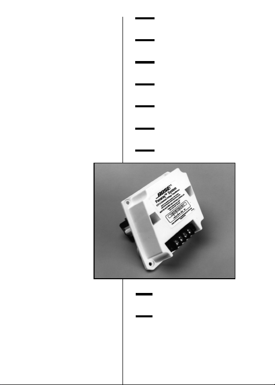
Thank you for purchasing the Bose® CVT-5 Constant Voltage Transformer
for the Panaray 502A Controlled Array. The CVT-5 is an integral, factorydesigned 70/100V transformer engineered for quick installation on the
502A array. The transformer handles up to 150W of power (in four
different taps) to accommodate a variety of distributed voice-only
application requirements. The compact, custom molded enclosure of the
CVT-5 attaches flush to the rear of the 502A array. This provides an
aesthetic advantage and a good fit when you use the CVT-5 transformer
in conjunction with Bose Panaray mounting accessories.
Before You Begin…
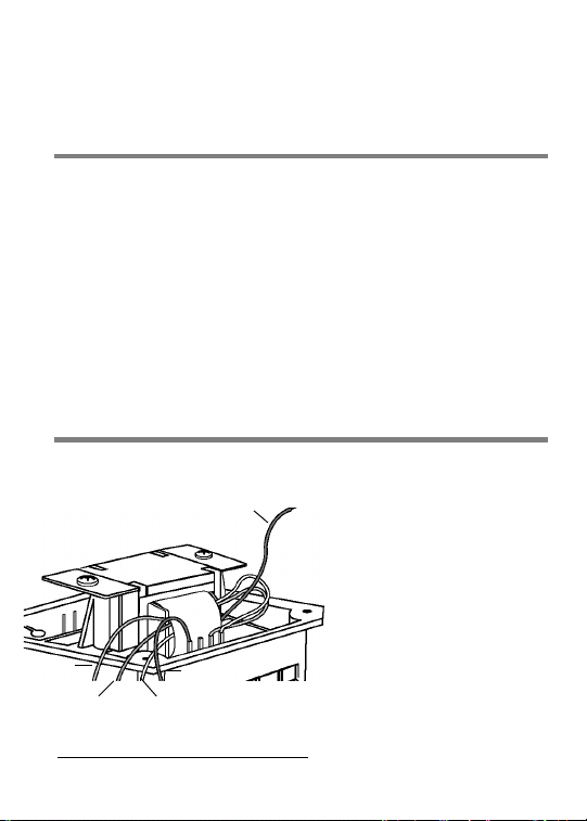
The transformer’s symmetrical housing allows you to attach the CVT-5
with its speaker terminals pointing away from or toward the 502A
array’s four rear attachment
points (Figure 1).
Before making the
attachment, consider which
orientation requires the
Blue
(75W)
Green
(38W)
White
(19W)
Black
(–)
least speaker cable. That may
help you decide the orientation
you prefer.
Figure 1
3
Page 4

Attaching The CVT-5 Transformer To
The
502®A Array
1. Use a Phillips head screwdriver to remove the
four screws that secure the connector plate to
the rear of the 502A array (Figure 2).
2. Use a small slot screwdriver to carefully pry the
connector away from the rear baffle. Pull it out a
short distance (Figure 3).
3. Use wire cutters to cut the two wires near the
solder terminals on the inside of the connector
panel (Figure 3). Put the panel aside.
Strip 1¦2" (12 mm) of insulation from the end of the two wires
4.
inside the 502A array.
4
Page 5
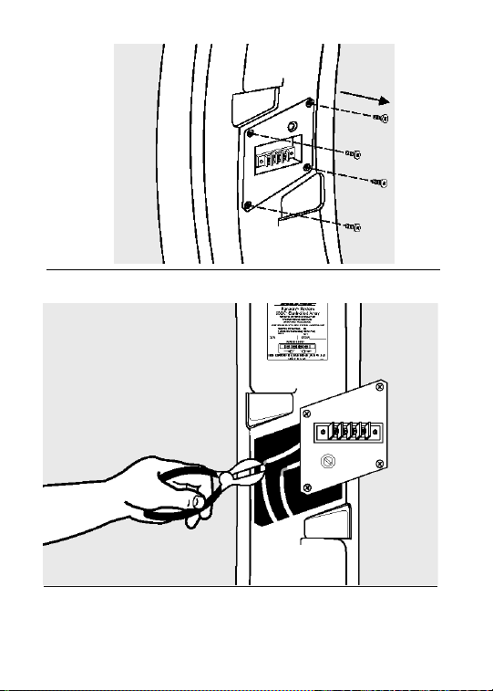
Figure 2
Figure 3
5
Page 6

5. A. Identify the positive output lead from the trans-former
according to the system’s power require-ments (see
table below). That lead’s power rating indicates where
you will “tap” the transformer.
Red ................................................ 150W
Blue ........................................ 75W
Green ..................................... 38W
White ...................................... 19W
B. Pull the cutaway tip of the insulation off that lead.
C. Clip the three unused leads off at the transformer
windings (Figure 4a).
D. Connect the positive lead, which is hanging loose, to
the red wire inside the array (Figure 4b).
E. Connect the black wire on the CVT-5 transformer to the
black wire inside the array.
Note: Soldering and insulating with electrical tape is the method
®
recommends for connecting wires. Using a small crimp-type
Bose
butt splicer is also acceptable.
We do not recommend wire nuts, terminal blocks, or similar
solderless devices, which could rattle inside the 502
®
A array or
touch the rear of one of the driver cones during use of the system.
6
Page 7

–
Figure 4a
+
Figure 4b
7
Page 8

6. Press the CVT-5 transformer housing down into
the flange in the orientation you prefer.
7. Use the four screws removed from the connector
plate to secure the CVT-5 to the array (Figure 5).
Figure 5
8
Page 9

Electrical Connections
Notice the arrangement of terminals on the back of the
CVT-5 transformer housing (Figure 6).
1. For 70V systems, connect the positive or hot
speaker lead coming from the amplifier to the
terminal labeled +70V. For100V systems,
connect the positive lead to the terminal labeled
+100V.
Figure 6
9
Page 10

2. Connect the ground or negative lead to the
terminal labeled GND. Do not use the terminal
marked N/C, which has no function.
3. For parallel connections in a chain, connect the
next array’s cable to the same terminals used
above.
Note: Bose® recommends using solder-type spade lugs on the ends
of the speaker cables. To make parallel connections efficiently, you
can attach the ends of the incoming and outgoing cables to a
single pair of spade lugs, which then attach to the selected
terminals.
If you do not use spade lugs, make sure that the incoming and
outgoing cables are of the same diameter. That will ensure an equal
force on them from the terminal strip flanges.
10
Page 11

Note On Painting
If you plan to paint the 502®A arrays, Bose® recommends
installing each CVT-5 transformer first, so you can paint
the 502A/CVT-5 assemblies all at once.
Before painting, mask off the label on the rear of the
transformer housing to preserve identification of the input
terminals.
For full instructions on painting the Panaray® components
and accessories, please consult the Bose Panaray
Installation Guide.
Note On Replacement Parts
If you have trouble installing or operating the CVT-5 Constant
Voltage Transformer, contact Bose Technical Service. Call (800)
367-4008 or (508) 366-9896. Or refer to the “For Information” listing
on page 12.
11
Page 12

For Information
USA
1-800-444-BOSE (2673) 8:30
a.m. to 9 p.m. ET
Canada
1-800-444-BOSE (2673)
9 a.m. to 5 p.m. ET
European Headquarters
Bose B.V., Nijverheidstraat 8,
1135 GE Edam, Netherands
TEL 0 2993-71055
FAX 0 2993-68163
Australia
Bose Australia, Inc.,
11 Muriel Avenue,
Rydalmere, N.S.W. 2116
TEL 02 684-1022
FAX 02 684-1665
Belgique/België
Bose N.V., Essenestraat
15,1740 Ternat
TEL 02-5826200
FAX 02-5823717
Danmark
Bose A/S, Industrivej 7, 2605
Brøndby
TEL 4343-7777
FAX 4343-7818
Deutschland
Bose GmbH, Max-Planck-Straße
36, Postfach 1125,
61381 Friedrichsdorf,
TEL 06172-71040
FAX 06172-710419
Epaña
Bose Products B.V., Avda.
Aragón 334, 28022 Madrid
TEL 01-3290210
FAX 01-7472080
France
Bose S/A, 6, rue Saint Vincent,
78100 Saint-Germain-en-Laye
TEL 01-30610461
FAX 01-30614105
Ireland
12
Page 13

Bose Ltd., Castleblayney Road,
Carrickmacross,
Co Monaghan
TEL 042-61988
FAX 042-61998
Italia
Bose S.p.A., Via Luigi Capucci
12, 00147 Rome TEL
06-5127641/2
FAX 06-5115438
Nederland
Bose B.V., Nijverheidstraat
8,1135 GE Edam
TEL 02993-66661
FAX 02993-68166
Norge
Bose A/S, Sundkroken 9H,
2008 Fjerdingby
TEL 63-838703
FAX 63-838704
Schweiz
Bose A.G., Rünenbergerstrasse
13A,
4460 Gelterkinden
TEL 061-995544
FAX 061-995502
Sverige
Bose A/S, Blandsädsgatan 2D,
43146 Mölndal
TEL 031-878850
FAX 031-274891
United Kingdom
Bose U.K. Ltd., Trinity Trading
Estate, Sittingbourne,
Kent ME10 2PD
TEL 0795-475341/5 FAX
0795-427227
Other Locations
Bose Service, Otis Street Park,
Building 3, PO Box 5045,
Westborough, MA 01581-5045
USA
TEL (508) 366-9896 FAX
(508) 366-8443
13
Page 14

14
©1996 Bose Corporation, The Mountain,
Framingham, MA 01701-9168 U.S.A.
JN93712 PN172164 Rev. 01 AM172164 Rev. 01
 Loading...