

Page 1
Companion® 3 Multimedia
Speaker System
Product Description
The Companion 3 multimedia speaker system is a stereo system designed to be used as a computer sound
system. It can be used with any analog audio source. It has a bass module with a 6.5 inch dual voice coil
woofer in a slot ported design. The two satellite speakers connect to the bass module and are easily mounted
to a monitor with brackets, or can be placed on a desk or other desired surface. A wired remote control pod is
used to control volume and mute/un-mute functions. It also has a second input and a stereo headphone output.
Manufacturing Information - Early Version / Later Version
There are two different versions of the Companion 3 - Early Version / Later Version. From the outside there is
basically no difference but the boards inside are different. Please note the differences are documented in the
Electronic Part list. If a part numbers has changed from the early version or a part number has been added to
the later version a number 4 will be shown in Notes column. The product codes can be used to determined the
version. The product code for the early version is 033935 and the product code for the later version is 033061.
These product codes are the first six digits of the serial number and are located on the bottom of the system.
The serial number should be used to determined where the system was manufactured before attempting a
repair.
©2007 Bose Corporation
Reference Number 271885-SM Rev. 11
Service Manual
Electronic copy only
Page 2

Contents
Safety Information .............................................................................................................................3
Electrostatic Discharge Sensitive (ESDS) Device Handling ....................................................... 3
Specifications....................................................................................................................................4
Part List Notes ..................................................................................................................................5
Figure 1. Bass Module Assembly Exploded View ................................................................................6
Bass Module Assembly Parts List ...................................................................................................6
Figure 2. Amplifier Module Assembly Exploded View ...........................................................................7
Amplifier Module Assembly Parts list..............................................................................................7
Figure 3. Packing Exploded Veiw ........................................................................................................ 8
Packing Parts List .............................................................................................................................8
Electrical Parts List .................................................................................................................... 9-19
Main PCB Assembly Parts List................................................................................................... 9-17
Power Supply PCB Assembly Parts List ................................................................................. 17-19
Disassembly Procedures ......................................................................................................... 20-22
Test Procedures ....................................................................................................................... 23-25
Theory of Operation ................................................................................................................. 26-28
Revision History .............................................................................................................................29
Theory of Operation ................................................................................................................. 26-28
Warranty
The Bose® Companion® 3 MultiMedia Speaker System is covered by a 1-year, transferable limited
warranty.
Proprietary Information
THIS DOCUMENT CONTAINS PROPRIETARY INFORMATION OF BOSE
CORPORATION WHICH IS BEING FURNISHED ONLY FOR THE PURPOSE OF
SERVICING THE IDENTIFIED BOSE PRODUCT BY AN AUTHORIZED BOSE
SERVICE CENTER OR OWNER OF THE BOSE PRODUCT, AND SHALL NOT
BE REPRODUCED OR USED FOR ANY OTHER PURPOSE.
Caution: The Companion 3 MultiMedia Speaker System contains no user serviceable parts.
To prevent warranty infractions, refer servicing to warranty service centers or factory service.
2
Page 3

Safety Information
1. Parts that have special safety characteristics are identified by the symbol on the schematics
or by special notes on the parts list. Use only replacement parts that have critical characteristics
recommended by the manufacturer.
2. Make leakage current or resistance measurements to determine that exposed parts are acceptably
insulated from the supply circuit before returning the unit to the customer. Use the following checks to
perform these measurements:
A. Leakage Current Hot Check- With the unit completely reassembled, plug the AC line cord directly
into a 120V AC outlet. (Do not use an isolation transformer during this test). Use a leakage current
tester or a metering system that complies with the American National Standards Institute (ANSI)
C101.1 “Leakage Current for Appliances” and the Underwriters Laboratories (UL) 6500/IEC 60056
paragraph 9.1.1. With the unit AC switch first in the ON position and then in the OFF position, measure from a known earth ground (metal waterpipe, conduit, etc.) to all exposed metal parts of the unit
(antennas, handle bracket, metal cabinet, screwheads, metallic overlays, control shafts, etc.) especially any exposed metal parts that offer an electrical return path to the chassis. Any current measured
must not exceed 0.5 milliamp. Reverse the unit power cord plug in the AC outlet and repeat the test.
ANY MEASUREMENTS NOT WITHIN THE LIMITS SPECIFIED HEREIN INDICATE A POTENTIAL
SHOCK HAZARD THAT MUST BE ELIMINATED BEFORE RETURNING THE UNIT TO THE CUSTOMER.
B. Insulation Resistance Test Cold Check- (1) Unplug the power supply and connect a jumper wire
between the two prongs of the plug. (2) Turn on the power switch of the unit. (3) Measure the resistance with an ohmmeter between the jumpered AC plug and each exposed metallic cabinet part on
the unit. When testing 3 wire products, the resistance measured to the product enclosure should be
between 2 and infinite MOhms. Also, the resistance measured to exposed input/output connectors
should be between 4 and infinite MOhms. When testing 2 wire products, the resistance measured to
exposed input/output connectors should be between 4 and infinite MOhms. If it is not within the limits
specified, there is the possibility of a shock hazard, and the unit must be repaired and rechecked
before it is returned to the customer.
Electrostatic Discharge Sensitive (ESDS)
Device Handling
This unit contains ESDS devices. We recommend the following precautions when repairing, replacing
or transporting ESDS devices:
•Perform work at an electrically grounded work station.
•Wear wrist straps that connect to the station or heel straps that connect to conductive floor mats.
•Avoid touching the leads or contacts of ESDS devices or PC boards even if properly grounded.
Handle boards by the edges only.
•Transport or store ESDS devices in ESD protective bags, bins, or totes. Do not insert unprotected
devices into materials such as plastic, polystyrene foam, clear plastic bags, bubble wrap or plastic
trays.
3
Page 4

Specifications
Mechanical
Dimensions: Bass Module: 8 5/8 “H x 7 1/8” W x 14” D
(21.8 x 18 x 35.56 cm)
Satellite Speaker: 3 1/2” H x 2 1/2” W x 2 3/8” D
(8.89 x 6.35 x 6.10 cm)
Control Pod: 2 1/2 “D x 1 1/8” H
(6.35 x 2.79 cm)
Weight: Bass Module: 15.4 lbs (6.98 kg) unpacked
Satellite Speaker: 0.5 lbs (0.23 kg) each
Packaged System 19.95 lbs (9.06 kg) packed
Finish: Bass Module: Scratch-resistant, satin-finish
vinyl
Satellites: Painted polymer finish
Bass Box: Slot ported
Bass Box Port Tuning: 45 Hz
Electrical
Power Rating: USA/Canada: 115 VAC 50/60 Hz
Japan 100 VAC 50/60 Hz
Euro 230 VAC 50/60 Hz
Nominal System
Bandwidth:
Maximum SPL: 100 dB (A weighted) pink
Output: Bass: 60 Watts
Satellites: 18 Watts per channel
40 Hz to 15 kHz
noise signal
4
Page 5

Part List Notes
1. This part is not normally available from Customer Service. Approval from the Field Service Manager
is required before ordering.
2. The individual parts on the PCBs are listed in the Electrical Part list.
3. This part is critical for safety purposes. Failure to use a substitute replacement with the same
safety characteristics as the recommended replacement part might create shock, fire and/or other
hazards.
4. The part number listed was included in the latest version of the Companion 3. The Main board and
the Power board for the latest version can be identified by the part number stamped on the component side of the board.
Power Board - 285350-001
Main Board - 280066-001
5. The part number listed is an assembly part number. The individual parts of the assembly might not
be available separately.
6. This part is referenced for informational purposes only. It is not stocked as a repair part. Refer to
the next higher assembly for a replacement part.
5
Page 6
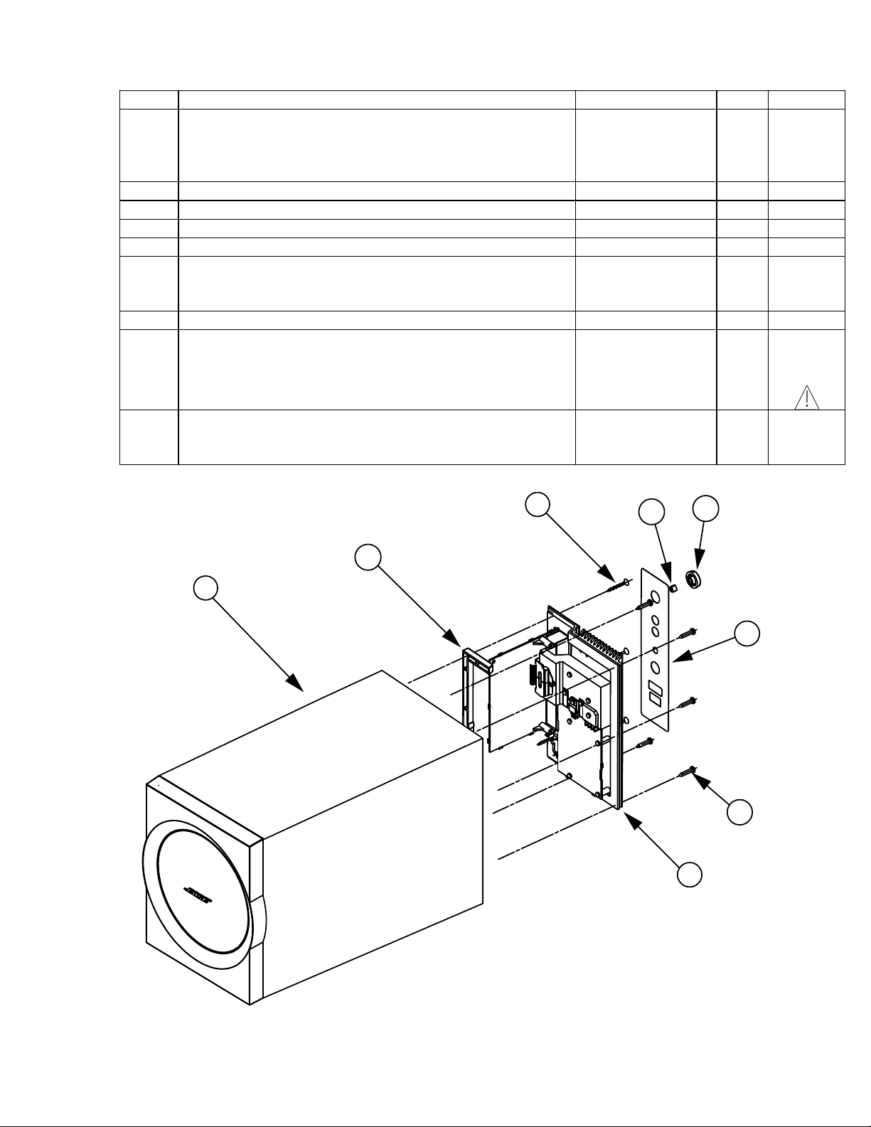
Item Description Part Number Qty. Note
1 BASS MODULE ASSY, US/CANADA, 120V
BASS MODULE ASSY, JAPAN, 100V
BASS MODULE ASSY, EURO, 230V
(Complete package, includes Amp Mod Assy.)
2 CLEAT, ABS 271817-001 1
3 SCREW, 4 x 1, THDF, FLHD, 82 DEG, PH 274151-16 3
4 CLIP, SPRING, KNOB 262542 1
5 KNOB, VOL CNTL, BLK 271860-001 1
6 LABEL, I/O, US/CANADA, 120V
LABEL, I/O, JAPAN, 100V
LABEL, I/O, EURO, 230V
7 SCREW, TF, 4 x 3/4, PAN, PH, BLK 273556-12 5
8 MOD ASSY, AMP, 120V
MOD ASSY, AMP, 220V, EURO
MOD ASSY, AMP, 100V JAPAN
*282451-001
*282451-002
*282451-003
272079-001
272079-002
272079-003
*307876-011
*307876-033
*307876-022
1
1
1
1
1
1
1
5
5
5
3
3,4
3,4
- XFORMER, TORROID, 105W, 15VDC, 7A
TRANSFORMER, TOROID, 100V, 60Hz
TRANSFORMER, TOROID, 230V, 50Hz
*Capacitor C7 on the new power supply board may need to be replaced, see Service Bulletin 271885-B4
X3
3
271818-001
N/A
277613-001
4
1
5
2
1
6
X5
7
Figure 1. Bass Module Assembly Exploded View
6
8
Page 7
23
1
4
5
6
7
8
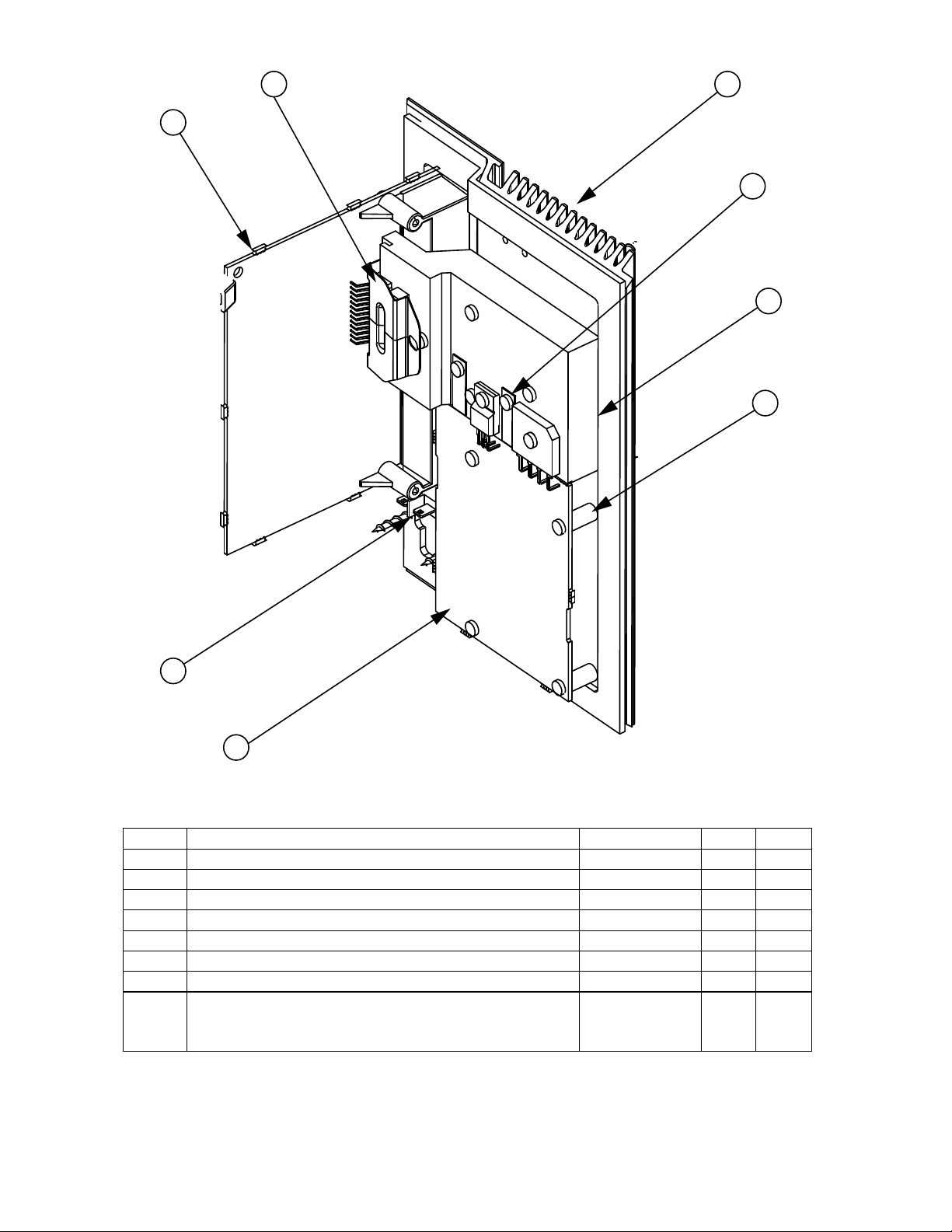
Figure 2. Amplifier Module Assembly
Item Description Part Number Qty. Note
1 PCB ASSY, MAIN 280109-01 1 6
2 BRACKET, METAL, IC 271859 1 6
3 HEATSINK, EXTRUDED, COMP 3 271856 1 6
4 CLIP, THERMAL, THERMISTOR 272964-001 1 6
5 HEAT SPREADER, ALUM 279844-001 1 6
6 SCREW, TAPP, 6-13x.625, PAN, XRC/S 172783-10 4
7 CONN, SWITCH, POWER, 3P 273115-001 1 6
8 PCB ASSY, PS, 120V, US
PCB ASSY, PS, 100V, JAPAN
PCB ASSY, PS, 240V, EURO
*Capacitor C7 on the new power supply board may need to be replaced, see Service Bulletin 271885-B4
307872-011
307872-022
307872-033
1
1
1
4
4
4
7
Page 8
X2
16
4
17
1
2
3
6
5
10
15
78
11 12
X2
9
13 14
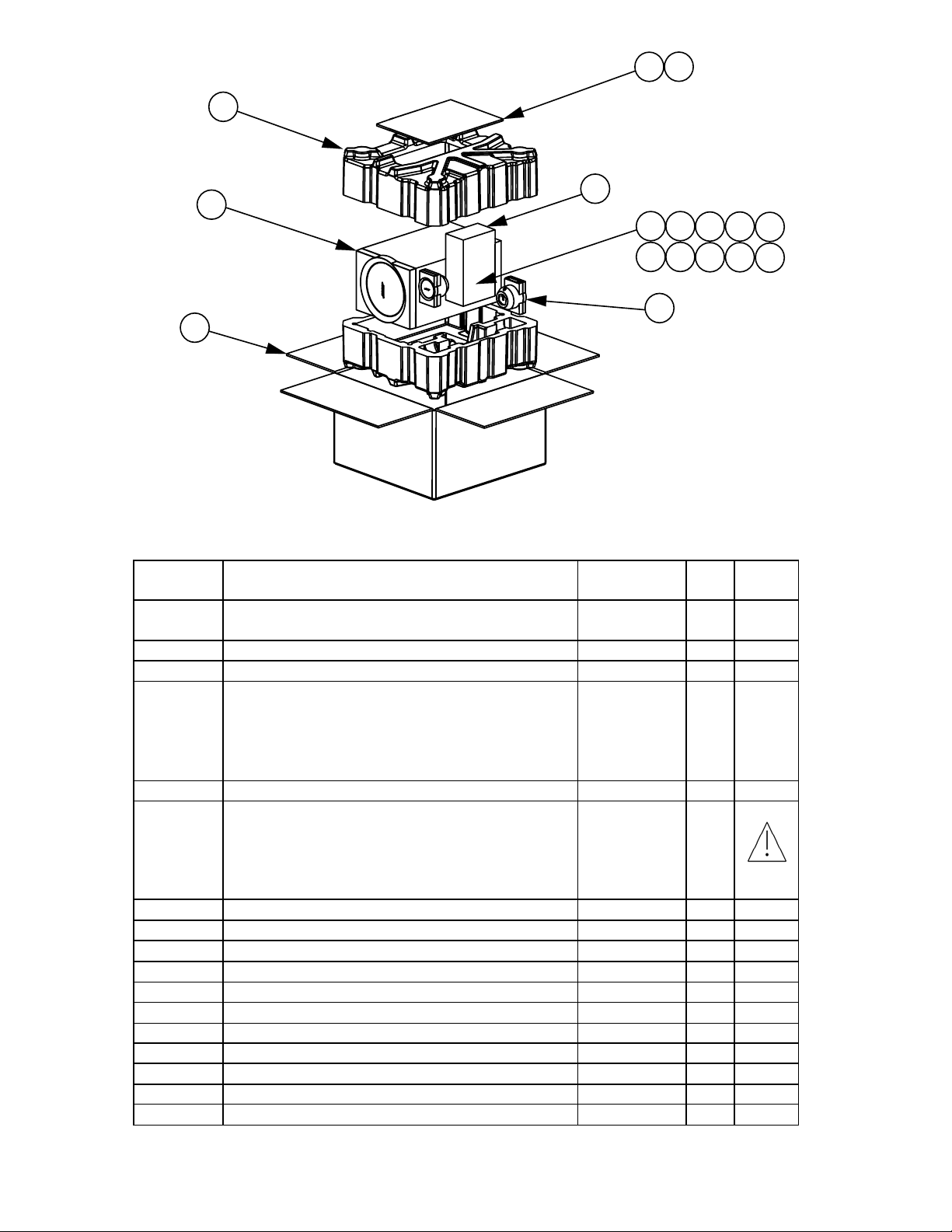
Figure 3. Packaging Exploded View
Item
Number
1 OWNER’S GUIDE US/CANADA
OW NER ’ S GUI DE 5 LA NG
2 BA G , PO LY, 14.38 x 9.87 x 2 mi l 1 03 351 1
3 PACKING TUBE, 4.75 x 2.75 x 7.69 273522 1
4 BASS MOD ULE ASSY, US/CANADA, 120V
BASS MODULE ASSY, EUR O, 230V
BASS MODULE ASSY, JAPAN , 100V
(Compl ete package, i ncl u des Amp M od
Assy.)
5 CONTROL POD (NON-REPAIRABLE) 307874-001 1 5
6 LINE CORD, 100 V, BLK, JAPAN
LINE C ORD, 120V, BLK, US/CANADA
LINE C ORD, 220V, BLK, EURO
LINE CORD , 23 0V, BLK, UK
LINE C ORD, 240V, BLK, AUS
7 BRACKET, SAT, LEFT 271880-001 1
8 BRACKET, SAT, RGHT 271881-001 1
9 CABLE, INPUT, 3.5MM, 6FT, BLK 2719 94-001 1
10 SCREW, MACH , M 4 x 0.5, PAN 272963-08 2
11 BA G , PO LY, 14.38 x 9.87 x 2 mi l 1 03 351 1
12 FASTENER, RD, CLR, 21MM OD, PSA 273164 2
13 FEET, CLEAR, SATELLITE 178321-04 16
14 FEET, RUBBER, BRACKET 260465 4
15 SAT ASSY, BLACK/GRAY 271827-019 2
16 CARTON, RSC, P RINTED 272410 1
17 PACKING, EPS, FILLERS 272409 2
Description Part
Number
271883-001
272956
282451-001
282451-002
282451-003
264514-001
262814-001
148203
134725
284243-001
Qty. Notes
1
1
1
1
1
1
1
1
1
1
5
4,5
4,5
3
8
Page 9

ELECTRICAL PARTS LIST
Main PCB Assembly
Resistors
Reference
Designator
R1 1.00K, 0805, 1/10W, 1% 133625-1001
R4 1.00K, 0805, 1/10W, 1% 133625-1001
R2 1.00K, 0805, 1/10W, 1% 133625-1001
R3 1.00K, 0805, 1/10W, 1% 133625-1001
R5 2.00K, 0805, 1/10W, 1% 133625-2001
R6 JUMPER, CHIP, 0805 133627
R101 1.21K, 0805, 1/10W, 1% 133625-1211
R102 1.30K, 0805, 1/10W, 1% 133625-1301
R103 9.53K, 0805, 1/10W, 1% 133625-9531
R104 10.0K, 0805, 1/10W, 1% 133625-1002
R105 127K 0805, 1/10W, 1% 133625-1273
R106 127K 0805, 1/10W, 1% 133625-1273
R107 10.0K, 0805, 1/10W, 1% 133625-1002
R108 10.0K, 0805, 1/10W, 1% 133625-1002
R109 2.00K, 0805, 1/10W, 1% 133625-2001
R110 10.0K, 0805, 1/10W, 1% 133625-1002
R111 10.0K, 0805, 1/10W, 1% 133625-1002
R125 2.55K, 0805, 1/10W, 1% 133625-2551
R126 200K, 0805, 1/10W, 1% 133625-2003
R127 47.5K, 0805, 1/10W, 1% 133625-4752
R128 1.10K, 0805, 1/10W, 1% 133625-1101
R129 21.5K, 0805, 1/10W, 1% 133625-2152
R130 330 OHM, 0805, 1/10W, 1% 133625-3300
R131 6.81K, 0805, 1/10W, 1% 133625-6811
R132 17.4K, 0805, 1/10W, 1% 133625-1742
R133 1.62K, 0805, 1/10W, 1% 133625-1621
R134 2.00K, 0805, 1/10W, 1% 133625-2001
R135 1.00K, 0805, 1/10W, 1% 133625-1001
R136 1.82K, 0805, 1/10W, 1% 133625-1821
R137 10.0K, 0805, 1/10W, 1% 133625-1002
R138 2.00K, 0805, 1/10W, 1% 133625-2001
R139 1.50K, 0805, 1/10W, 1% 133625-1501
R140 1.50K, 0805, 1/10W, 1% 133625-1501
R201 1.21K, 0805, 1/10W, 1% 133625-1211
R202 1.30K, 0805, 1/10W, 1% 133625-1301
R203 9.53K, 0805, 1/10W, 1% 133625-9531
R204 127K 0805, 1/10W, 1% 133625-1273
R205 10.0K, 0805, 1/10W, 1% 133625-1002
R206 127K 0805, 1/10W, 1% 133625-1273
R207 10.0K, 0805, 1/10W, 1% 133625-1002
R208 10.0K, 0805, 1/10W, 1% 133625-1002
R209 10.0K, 0805, 1/10W, 1% 133625-1002
R210 10.0K, 0805, 1/10W, 1% 133625-1002
R211 2.00K, 0805, 1/10W, 1% 133625-2001
Description Part Number Note
9
Page 10

ELECTRICAL PARTS LIST
Main PCB Assembly
Resistors (continued)
Reference
Designator
R225 100K, 0805, 1/10W, 1% 133625-1003
R226 100K, 0805, 1/10W, 1% 133625-1003
R227 JUMPER, CHIP, 0805 133627
R229 2.55K, 0805, 1/10W, 1% 133625-2551
R230 200K, 0805, 1/10W, 1% 133625-2003
R231 47.5K, 0805, 1/10W, 1% 133625-4752
R232 1.10K, 0805, 1/10W, 1% 133625-1101
R233 21.5K, 0805, 1/10W, 1% 133625-2152
R234 330 OHM, 0805, 1/10W, 1% 133625-3300
R235 6.81K, 0805, 1/10W, 1% 133625-6811
R236 17.4K, 0805, 1/10W, 1% 133625-1742
R237 1.62K, 0805, 1/10W, 1% 133625-1621
R238 2.00K, 0805, 1/10W, 1% 133625-2001
R239 1.00K, 0805, 1/10W, 1% 133625-1001
R240 1.82K, 0805, 1/10W, 1% 133625-1821
R241 10.0K, 0805, 1/10W, 1% 133625-1002
R242 2.00K, 0805, 1/10W, 1% 133625-2001
R243 1.50K, 0805, 1/10W, 1% 133625-1501
R244 1.50K, 0805, 1/10W, 1% 133625-1501
R301 1.00K, 0805, 1/10W, 1% 133625-1001
R301 100 OHM, 0805, 1/10W, 1% 133625-1000 4
R301 100 OHM, 0805, 1/10W, 1% 133625-1000 Euro /UK /Aus
R302 1.00K, 0805, 1/10W, 1% 133625-1001
R302 100 OHM, 0805, 1/10W, 1% 133625-1000 4
R302 100 OHM, 0805, 1/10W, 1% 133625-1000 Euro /UK /Aus
R305 10.0K, 0805, 1/10W, 1% 133625-1002
R306 10.0K, 0805, 1/10W, 1% 133625-1002
R307 1.20 OHMS, 2512, 1W, 5% 181895-1R20 Euro /UK /Aus
R308 1.00K, 0805, 1/10W, 1% 133625-1001
R309 100 OHM, 0805, 1/10W, 1% 133625-1000
R310 100 OHM, 0805, 1/10W, 1% 133625-1000
R311 JUMPER, CHIP, 0805 133627
R311 1.00K, 0805, 1/10W, 5% 133626-1025 4
R312 JUMPER, CHIP, 0805 133627
R312 1.00K, 0805, 1/10W, 5% 133626-1025 4
R314 1.00K, 0805, 1/10W, 1% 133625-1001
R315 1.00K, 0805, 1/10W, 1% 133625-1001
R316 249 OHM, 0805, 1/10W, 1% 133625-2490
R317 249 OHM, 0805, 1/10W, 1% 133625-2490
R318 100K, 0805, 1/10W, 1% 133625-1003
R319 249 OHM, 0805, 1/10W, 1% 133625-2490
R320 1.00K, 0805, 1/10W, 1% 133625-1001
R323 487K, 0805, 1/10W, 1% 133625-4873
R324 1.21K, 0805, 1/10W, 1% 133625-1212
Description Part Number Note
10
Page 11

ELECTRICAL PARTS LIST
Main PCB Assembly
Resistors (continued)
Reference
Designator
R325 1.21K, 0805, 1/10W, 1% 133625-1212
R327 20.0K, 0805, 1/10W, 1% 133625-2002
R327 JUMPER, CHIP, 0805 133627 4
R327 JUMPER, CHIP, 0805 133627 Euro
R328 JUMPER, CHIP, 0805 133627
R329 16.2K, 0805, 1/10W, 1% 133625-1622
R330 78.7K, 0805, 1/10W, 1% 133625-7872
R331 2.00K, 0805, 1/10W, 1% 133625-2001
R334 100K, 0805, 1/10W, 1% 133625-1003
R335 100K, 0805, 1/10W, 1% 133625-1003
R336 2.2 OHM, 0805, 1/10W, 5% 133626-2R25
R336 10 OHM, 2512, 1W, 5% 181895-10R0 Euro
R337 402 OHM, 0805, 1/10W, 1% 133625-4020
R337 162 OHM, 0805, 1/10W, 1% 133625-1620 Euro
R338 14.0K, 0805, 1/10W, 1% 133625-1402
R339 1.00K, 0805, 1/10W, 1% 133625-1001
R340 10.0K, 0805, 1/10W, 1% 133625-1002
R347 2.00K, 0805, 1/10W, 1% 133625-2001
R348 2.00K, 0805, 1/10W, 1% 133625-2001
R349 JUMPER, CHIP, 0805 133627
R350 JUMPER, CHIP, 0805 133627
R350 JUMPER, CHIP, 0805 133627 Euro
R351 JUMPER, CHIP, 0805 133627
R351 100 OHM, 0805, 1/10W, 1% 133625-1000 4
R351 100 OHM, 0805, 1/10W, 1% 133625-1000 Euro
R352 1.00K, 0805, 1/10W, 1% 133625-1001
R353 1.00K, 0805, 1/10W, 1% 133625-1001
R354 1.00K, 0805, 1/10W, 1% 133625-1001 4
R354 1.00K, 0805, 1/10W, 1% 133625-1001 Euro
R355 1.00K, 0805, 1/10W, 1% 133625-1001
R356 499K, RES, 0805, 1/10W, 1% 133625-4993 4
R357 10.0K, 0805, 1/10W, 1% 133625-1002 4
R358 1.1 OHM, SMD, FUSE, 1/10W, 5% 192349-1R1A
R359 1.1 OHM, SMD, FUSE, 1/10W, 5% 192349-1R1A
R360 1.1 OHM, SMD, FUSE, 1/10W, 5% 192349-1R1A
R360 1.1 OHM, SMD, FUSE, 1/10W, 5% 192349-1R1A Euro/UK/Aus
Description Part Number Note
3,4
3,4
3,4
3
R361 1.1 OHM, SMD, FUSE, 1/10W, 5% 192349-1R1A
R361 1.1 OHM, SMD, FUSE, 1/10W, 5% 192349-1R1A Euro/UK/Aus
R362 JUMPER, CHIP, 0805 133627 Euro
R401 100K, 0805, 1/10W, 1% 133625-1003
R402 10.0K, 0805, 1/10W, 1% 133625-1002
11
3,4
3
Page 12

ELECTRICAL PARTS LIST
Main PCB Assembly
Resistors (continued)
Reference
Designator
R403 221 OHM, 0805, 1/10W, 1% 133625-2210
R404 10.0K, 0805, 1/10W, 1% 133625-1002
R405 1.00K, 0805, 1/10W, 1% 133625-1001
R406 1.00K, 0805, 1/10W, 1% 133625-1001
R407 1.00K, 0805, 1/10W, 1% 133625-1001
R408 1.00K, 0805, 1/10W, 1% 133625-1001
R409 5.90K, 0805, 1/10W, 1% 133625-5901
R410 5.90K, 0805, 1/10W, 1% 133625-5901
R950 2.55K, 0805, 1/10W, 1% 133625-2551
R951 4.12K, 0805, 1/10W, 1% 133625-4121
R952 1.0M, 0805, 1/10W, 1% 133625-1004
R953 10.0K, 0805, 1/10W, 1% 133625-1002
R954 750 OHM, 0805, 1/10W, 1% 133625-7500
R956 88.7K, 0805, 1/10W, 1% 133625-8872
R957 1.21K, 0805, 1/10W, 1% 133625-1211
R958 10.0K, 0805, 1/10W, 1% 133625-1002
R959 1.00K, 0805, 1/10W, 1% 133625-1001
R960 36.5K, 0805, 1/10W, 1% 133625-3652
R961 36.5K, 0805, 1/10W, 1% 133625-3652
R962 1.0M, 0805, 1/10W, 1% 133625-1004
R963 26.7K, 0805, 1/10W, 1% 133625-2672
R964 750 OHM, 0805, 1/10W, 1% 133625-7500
R965 15.4K, 0805, 1/10W, 1% 133625-1542
R966 1.21K, 0805, 1/10W, 1% 133625-1213
R967 1.00K, 0805, 1/10W, 1% 133625-1001
R968 4.99K, 0805, 1/10W, 1% 133625-4991
R969 JUMPER, CHIP, 0805 133627
R970 20.0K, 0805, 1/10W, 1% 133625-2002
R971 10.0K, 0805, 1/10W, 1% 133625-1002
R972 49.9K, 0805, 1/10W, 1% 133625-4992
R973 1.21K, 0805, 1/10W, 1% 133625-1211
R974 1.00K, 0805, 1/10W, 1% 133625-1001
R975 10.0K, 0805, 1/10W, 1% 133625-1002
R976 5.90K, 0805, 1/10W, 1% 133625-5901
R977 100 OHM, 0805, 1/10W, 1% 133625-1000
R978 100K, 0805, 1/10W, 1% 133625-1003
R979 10.0K, 0805, 1/10W, 1% 133625-1002
R980 4.99K, 0805, 1/10W, 1% 133625-4991
R981 100K, 0805, 1/10W, 1% 133625-1003
R982 1.00K, 0805, 1/10W, 1% 133625-1001
R983 1.00K, 0805, 1/10W, 1% 133625-1001
R986 Potentiometer, 10K, +/- 20%, 1B 273741-001
R987 1.54K, 0805, 1/10W, 1% 133625-1541
Description Part Number Note
12
Page 13

ELECTRICAL PARTS LIST
Main PCB Assembly
Capacitors
Reference
Designator
C001 10000pf, MONO, 100V, 20% 180630-103 4
C002 10000pf, MONO, 100V, 20% 180630-103 4
C101 2.2uF, 1206, X7R, 10V, 20% 260361-2253
C102 .0068uF, BOX, 85C, 100V, 5% 137127-682
C103 .033uF, BOX, 85C, 63V, 5% 137127-333
C104 1000pF, 0805, COG, 50V, 5% 133622-102
C105 100pF, 0805, COG, 50V, 5% 133622-101
C110 68pF, 0603, COG, 50V, 5% 188454-680 Euro/UK/Aus
C111 68pF, 0603, COG, 50V, 5% 188454-680 Euro/UK/Aus
C112 68pF, 0603, COG, 50V, 5% 188454-680 Euro/UK/Aus
C125 .12uF, BOX, 85C, 50V, 5% 137127-124
C126 .12uF, BOX, 85C, 50V, 5% 137127-124
C127 .18uF, BOX, 85C, 50V, 5% 137127-184
C128 .01uF, BOX, 85C, 100V, 5% 137127-103
C129 .01uF, BOX, 85C, 100V, 5% 137127-103
C130 .0015uF, BOX, 85C, 100V, 5% 137127-152
C131 .0056uF, BOX, 85C, 100V, 5% 137127-562
C132 .12uF, BOX, 85C, 50V, 5% 137127-124
C133 .12uF, BOX, 85C, 50V, 5% 137127-124
C134 1000pF, 0805, COG, 50V, 5% 133622-102
C201 2.2uF, 1206, X7R, 10V, 20% 260361-2253
C202 .0068uF, BOX, 85C, 100V, 5% 137127-682
C203 .033uF, BOX, 85C, 63V, 5% 137127-333
C204 100pF, 0805, COG, 50V, 5% 133622-101
C210 68pF, 0603, COG, 50V, 5% 188454-680 Euro/UK/Aus
C225 .12uF, BOX, 85C, 50V, 5% 137127-124
C226 .12uF, BOX, 85C, 50V, 5% 137127-124
C227 .18uF, BOX, 85C, 50V, 5% 137127-184
C228 .01uF, BOX, 85C, 100V, 5% 137127-103
C229 .01uF, BOX, 85C, 100V, 5% 137127-103
C230 .0015uF, BOX, 85C, 100V, 5% 137127-152
C231 .0056uF, BOX, 85C, 100V, 5% 137127-562
C232 1000pF, 0805, COG, 50V, 5% 133622-102
C233 .12uF, BOX, 85C, 50V, 5% 137127-124
C234 .12uF, BOX, 85C, 50V, 5% 137127-124
C235 .1uF 0805, X7R, 10%, 25V 181264-104
C236 10uF, EL, SMD, 105, 25V, 20% 255071-100E
C237 .1uF, 0805, X7R, 10%, 25V 181264-104
C238 10uF, EL, SMD, 105, 25V, 20% 255071-100E
C239 .1uF, 0805, X7R, 10%, 25V 181264-104
C240 68pF, 0603, COG, 50V, 5% 188454-680 Euro/UK/Aus
C241 68pF, 0603, COG, 50V, 5% 188454-680 Euro/UK/Aus
C301 100pF, 0805, COG, 50V, 5% 133622-101
C302 3300pF, 0805, X7R, 50V, 10% 133623-332
C303 100pF, 0805, COG, 50V, 5% 133622-101
C305 3300pF, 0805, X7R, 50V, 10% 133623-332
Description Part Number Note
13
Page 14

ELECTRICAL PARTS LIST
Main PCB Assembly
Capacitors (continued)
Reference
Designator
C306 1uF, EL, SMD, 105, 50V, 20% 255071-1R0H
C307 1uF, EL, SMD, 105, 50V, 20% 255071-1R0H
C308 100pF, 0805, COG, 50V, 5% 133622-101
C309 .015uF, 0805, X7R, 50V, 10% 133623-153 Euro/UK/Aus
C310 100pF, 0805, COG, 50V, 5% 133622-101
C311 10uF, EL, SMD, 105, 25V, 20% 255071-100E
C312 100pF, 0805, COG, 50V, 5% 133622-101
C313 100uF, EL, SMD, 105, 25V, 20% 255071-101E
C314 10uF, EL, SMD, 105, 25V, 20% 255071-100E
C315 10uF, EL, SMD, 105, 25V, 20% 255071-100E
C316 0.1uF, 0805, X7R, 50V 133623-104
C317 0.1uF, 0805, X7R, 50V 133623-104
C318 .022uF, 0805, X7R, 50V, 10% 133623-223
C318 .1uF, 0805, X7R, 10%, 25V 181264-104 Euro/UK/Aus
C319 .022uF, 0805, X7R, 50V, 10% 133623-223
C319 .1uF, 0805, X7R, 10%, 25V 181264-104 Euro/UK/Aus
C320 .47uF, 0805, X7R, 16V, 5% 196995-474
C321 .015uF, BOX, 85C, 100V, 5% 137127-153
C322 47UF, EL, SMD, 105, 25V, 20% 255071-470E
C324 .015uF, BOX, 85C, 100V, 5% 137127-154
C325 0.1uF, 0805, X7R, 50V 133623-104
C326 100pF, 0805, COG, 50V, 5% 133622-101
C326 .01uF, 0805, X7R, 50V, 10% 133623-103 4
C326 .01uF, 0805, X7R, 50V, 10% 133623-103 Euro/UK/Aus
C327 .1uF, BOX, 85C, 50V, 5% 137127-104
C328 100pF, 0805, COG, 50V, 5% 133622-101
C328 .01uF, 0805, X7R, 50V, 10% 133623-103 4
C329 .1uF, BOX, 85C, 50V, 5% 137127-104
C330 100pF, 0805, COG, 50V, 5% 133622-101
C330 .01uF, 0805, X7R, 50V, 10% 133623-103 4
C330 .01uF, 0805, X7R, 50V, 10% 133623-103 Euro/UK/Aus
C331 100pF, 0805, COG, 50V, 5% 133622-101
C331 .01uF, 0805, X7R, 50V, 10% 133623-103 4
C331 .01uF, 0805, X7R, 50V, 10% 133623-103 Euro/UK/Aus
C332 1000pF, 0805, COG, 50V, 5% 133622-102
C333 100pF, 0805, COG, 50V, 5% 133622-101
C333 1000pF, 0805, COG, 50V, 5% 133623-102 Euro/UK/Aus
C333 .01uF, 0805, X7R, 50V, 10% 133623-103 4
C334 100pF, 0805, COG, 50V, 5% 133622-101
C334 1000pF, 0805, COG, 50V, 5% 133623-102 Euro/UK/Aus
C334 .01uF, 0805, X7R, 50V, 10% 133623-103 4
C335 100pF, 0805, COG, 50V, 5% 133622-101
C335 1000pF, 0805, COG, 50V, 5% 133623-102 Euro/UK/Aus
C335 .01uF, 0805, X7R, 50V, 10% 133623-103 4
C336 100pF, 0805, COG, 50V, 5% 133622-101
Description Part Number Note
14
Page 15

ELECTRICAL PARTS LIST
Main PCB Assembly
Capacitors (continued)
Reference
Designator
C336 1000pF, 0805, COG, 50V, 5% 133623-102 Euro/UK/Aus
C336 .01uF, 0805, X7R, 50V, 10% 133623-103 4
C337 10uF, EL, SMD, 105CC, 25V, 20% 255071-100E
C338 1000pF, 0805, COG, 50V, 5% 133622-102
C339 1000pF, 0805, COG, 50V, 5% 133622-102
C340 1000pF, 0805, COG, 50V, 5% 133622-102
C341 1000pF, 0805, COG, 50V, 5% 133622-102 4
C341 1000pF, 0805, COG, 50V, 5% 133622-102 Euro/UK/Aus
C342 47uF, EL, SMD, 105CC, 25V, 20% 255071-470E 4
C342 47uF, EL, SMD, 105CC, 25V, 20% 255071-470E Euro/UK/Aus
C343 1000pF, 0805, COG, 50V, 5% 133622-102 4
C343 1000pF, 0805, COG, 50V, 5% 133622-102 Euro/UK/Aus
C348 .01uF, 0805, X7R, 50V, 10% 133623-103 Euro/UK/Aus
C349 .01uF, 0805, X7R, 50V, 10% 133623-103 Euro/UK/Aus
C350 .01uF, 0805, X7R, 50V, 10% 133623-103 Euro/UK/Aus
C351 .01uF, 0805, X7R, 50V, 10% 133623-103 Euro/UK/Aus
C352 68pF, 0603, COG, 50V, 5% 188454-680 Euro/UK/Aus
C353 68pF, 0603, COG, 50V, 5% 188454-680 Euro/UK/Aus
C354 68pF, 0603, COG, 50V, 5% 188454-680 Euro/UK/Aus
C355 68pF, 0603, COG, 50V, 5% 188454-680 Euro/UK/Aus
C360 .01uF, 0805, X7R, 50V, 10% 133623-103 Euro/UK/Aus
C401 10uF, EL, SMD, 105C, 25V, 20% 255071-100E
C402 .01uF, 0805, X7R, 50V, 10% 133623-103
C403 .01uF, 0805, X7R, 50V, 10% 133623-103
C404 1000pF, 0805, COG, 50V, 5% 133622-102
C950 10uF, EL, SMD, 105C, 25V, 20% 255071-100E
C951 68pF, 0603, COG, 50V, 5% 188454-680 Euro/UK/Aus
C952 68pF, 0603, COG, 50V, 5% 188454-680 Euro/UK/Aus
C953 .12uF, BOX, 85C, 50V, 5% 137127-124
C954 .12uF, BOX, 85C, 50V, 5% 137127-124 4
C954 .12uF, BOX, 85C, 50V, 5% 137127-124 Euro/UK/Aus
C954 Film, 16V, 0.12uF, 5%, SMT 274313-124J
C955 10uF, EL, SMD, 105C, 25V, 20% 255071-100E
C956 .01uF, BOX, 85C, 100V, 5% 137127-103
C957 10uF, EL, SMD, 105C, 25V, 20% 255071-100E
C959 1000pF, 0805, COG, 50V, 5% 133622-102
C960 Film, 16V, 0.12uF, 5%, SMT 274313-124J
C960 .12uF, BOX, 85C, 50V, 5% 137127-124 4
C960 .12uF, BOX, 85C, 50V, 5% 137127-124 Euro/UK/Aus
C961 Film, 16V, 0.12uF, 5%, SMT 274313-124J
C961 .12uF, BOX, 85C, 50V, 5% 137127-124 4
C961 .12uF, BOX, 85C, 50V, 5% 137127-124 Euro/UK/Aus
C962 .0015uF, BOX, 85C, 100V, 5% 137127-152
C963 1000pF, 0805, COG, 50V, 5% 133622-102
C964 1000pF, 0805, COG, 50V, 5% 133622-102
C965 1000pF, 0805, COG, 50V, 5% 133622-102
Description Part Number Note
15
Page 16

ELECTRICAL PARTS LIST
Main PCB Assembly
Capacitors (continued)
Reference
Designator
C966 1000pF, 0805, COG, 50V, 5% 133622-102
C968 .01uF, 0805, X7R, 50V, 10% 133623-103
C969 10uF, EL, SMD, 105C, 25V, 20% 255071-100E
C970 1uF, EL, SMD, 105C, 50V, 20% 255071-1R0H
C971 .47uF, BOX, 85C, 50V, 5% 137127-474
C977 68pF, 0603, COG, 50V, 5% 188454-680 Euro/UK/Aus
C980 68pF, 0603, COG, 50V, 5% 188454-680 Euro/UK/Aus
C983 68pF, 0603, COG, 50V, 5% 188454-680 Euro/UK/Aus
C988 68pF, 0603, COG, 50V, 5% 188454-680 Euro/UK/Aus
Description Part Number Note
Inductors
Reference
Designator
L301 330 OHM, BEAD, FERRITE, 0805, 1.5A 267539-331 Euro/UK/Aus
Description Part Number Note
Diodes
Reference
Designator
D301 SOT-23, BAV 99 147239 Euro/UK/Aus
D301 ZEN, SOD-123, .5W, 5%, 10V 174265-5240
D302 SOT-23, BAV 99 147239
D303 SOT-23, BAV 99 147239
D304 SOT-23, BAV 99 147239
D305 SOT-23, BAV 99 147239
D306 SOT-23, BAV 99 147239 4
D306 SOT-23, BAV 99 147239 Euro/UK/Aus
D401 DUAL, SOT-23, BAW56 180738
D402 DUAL, SOT-23, BAW56 180738
D403 SOT-23, BAV 99 147239
D951 SOT-23, BAV 70 147249
D952 SOT-23, BAV 99 147239
D954 DUAL, SOT-23, BAW56 180738
D955 SOT-23, BAV 99 147239
ZR301 ZEN, SOD-123, .5W, 5%, 10V 174265-5240 Euro/UK/Aus
Description Part Number Note
16
Page 17

ELECTRICAL PARTS LIST
Main PCB Assembly
Transistors
Reference
Designator
Q303 BPLR, N, 50V, 800mA, SOT23 148770
Q303 NPN, 1.3W, SOT-223 258416-001 Euro/UK/Aus
Q303 NPN, SOT223, 40V, 200mA, 1W 275431 4
Q304 BPLR, P, 40V, 200mA, SOT23 148596
Q305 BPLR, N, 40V, 200mA, SOT23 146819
Q306 BPLR, P, 40V, 200mA, SOT23 148596
Q307 BPLR, P, 40V, 200mA, SOT23 148596
Q308 BPLR, N, 40V, 200mA, SOT23 146819
Q309 BPLR, N, 40V, 200mA, SOT23 146819
Q401 BPLR, N, 40V, 200mA, SOT23 146819
Q402 BPLR, P, 40V, 200mA, SOT23 148596
Q403 BPLR, P, 40V, 200mA, SOT23 148596
Q950 BPLR, N, 40V, 200mA, SOT23 146819
Q951 BPLR, P, 40V, 200mA, SOT23 148596
Q952 BPLR, P, 40V, 200mA, SOT23 148596
Q953 BPLR, N, 40V, 200mA, SOT23 146819
Q954 BPLR, P, 40V, 200mA, SOT23 148596
Description Part Number Note
Integrated Circuits
Reference
Designator
U102 IC, 0P AMP QUAD, SOIC-14, NJM2059 187472
U125 IC, 0P AMP QUAD, SOIC-14, NJM2059 187472
U201 IC, 0P AMP QUAD, SOIC-14, NJM2059 187472
U3 IC, 0P AMP QUAD, SOIC-14, NJM2059 187472
U301 IC, POWER AMP, 4x45W, 25-PIN 271833-001
U401 IC, TRANS, DUAL, SOIC-16, NJM13700 188650-001
U950 IC, TRANS, DUAL, SOIC-16, NJM13700 188650-001
U951 IC, 0P AMP QUAD, SOIC-14, NJM2059 187472
Description Part Number Note
Miscellaneous
Reference
Designator
J301 CONN, HEADER, 3 POS, .156 133220-03
J302 CONN, JACK, 3.5mm, PCB MNT, STEREO 177154-01
J302 CONN, JACK PHONE, 3.5MM 269841-001 4
J302 CONN, JACK PHONE, 3.5MM 269841-001 Euro/UK/Aus
J305 CONN, HEADER, INLINE, PCB MNT, 4P 133220-04
J307 CONN, RCA, DUAL, PC MOUNT 272376-001
J308 CONN, MINI DIN, R/A, 9-PIN 273227-001
Description Part Number Note
17
Page 18

ELECTRICAL PARTS LIST
Power Supply PCB Assembly
Resistors
Reference
Designator
R1 1.00K, 0805, 1/10W, 1% 133625-1001
R2 1.00K, 0805, 1/10W, 1% 133625-1001
R3 1.00K, 0805, 1/10W, 1% 133625-1001
R4 1.00K, 0805, 1/10W, 1% 133625-1001
R5 2.00K, 0805, 1/10W, 1% 133625-2001
R6 10.0 OHM, 0805,1/10W,1% 133625-10R0 4
R6 10.0 OHM, 0805,1/10W,1% 133625-10R0 Japan
R6 10.0 OHM, 0805,1/10W,1% 133625-10R0 Euro/UK/Aus
R6 JUMPER, CHIP, 0805 133627
R7 412 OHMS, 0805, 1/10W, 1% 133625-4120
R8 JUMPER, CHIP,0805 133627
R9 412 OHMS, 0805, 1/10W, 1% 133625-4120
R10 JUMPER, CHIP,0805 133627
R11 10.0 OHM, 0805,1/10W,1% 133625-10R0
RT1 22K, THERMISTOR, RADIAL, 1/4W, 5% 177557
RT2 22K, THERMISTOR, RADIAL, 1/4W, 5% 177557
VR1 VARISTOR, MET OX, 275V, 140 JOULE 273545-001
VR1 VARISTOR,MET OX, 300V, 140 JOULE
VR1 VARISTOR, MET OX, 175V, 140 JOULE
Description Part Number Note
TUBING,HEAT SHRINK, .75 INCH
TUBING,HEAT SHRINK, .75 INCH
273545-002
267807
273545-003
267807
Euro/UK/Aus
Japan
Capacitors
Reference
Designator
C1 1.0uF, BOX, 85, 100V, 5% 137127-105
C2 .22 uF, 0805, X7R, 10%, 25V 181264-224
C3 .047uF, 0805, X7R, 50V, 10% 133623-473
C4 .1uF, 0805, X7R, 10%, 25V 181264-104 4
C4 .1uF, 0805, X7R, 10%, 25V 181264-104 Japan
C4 .1uF, 0805, X7R, 10%, 25V 181264-104 Euro/UK/Aus
C4 .22 uF, 0805, X7R, 10%, 25V 181264-224
C5 .1uF, 0805, X7R, 10%, 25V 181264-104
C7 39000 uF, EL, AL, 25V 260693-3931E Euro/Japan
C7 33000 uFD, EL, AL, 25V, 4T 260693-3331E
C8 .22UF, FILM, X2, 275VAC, 15MM 268166-224B
Description Part Number Note
Inductors
Reference
Designator
L1 Choke, Common mode, with header 277667-001 4
L1 Choke, Common mode, with header 277667-001 Japan
L1 Choke, Common mode, with header 277667-001 Euro/UK/Aus
Description Part Number Note
18
Page 19

ELECTRICAL PARTS LIST
Power Supply PCB Assembly
Diodes
Reference
Designator
BR1 RECTIFIER, BRIDGE, 8A, 400V 260684-400
D1 13V, ZEN, SOD-123, .5W, 5% 174265-5243
D2 SOT-23, BAV 99 147239
Description Part Number Note
Transistors
Reference
Designator
Q1 BPLR, P, 40V, 200mA, SOT23 148596
Q2 BPLR, P, 40V, 200mA, SOT23 148596
Q3 MFET, N, 55V, TO-220FP 257359-001
Q4 BPLR, P, 40V, 200mA, SOT23 148596
Q5 BPLR, P, 40V, 200mA, SOT23 148596
Description Part Number Note
Miscellaneous
Reference
Designator
F1 FUSE, 4.0A, 125V, .60X.19, SLOBLO, US
F1 FUSE, 2.0 AMPS, AXIAL, EURO 269855-02000
F1 FUSE, 4.0A, 125V, .60X.19, SLOBLO, JAPAN 135677-12
J1 CONN, HEADER, LOCKING, TOP ENTRY 193369-002
J2 CONN, HEADER, 3.96mm, 7-pin 272385-07
J3 CONN, HEADER, 3 POS, .156 133220-03
J5 CONN, AC LINE, PC MOUNT 272684-001
J5 CONN, AC LINE, PC MOUNT 277580-001 Japan/Euro
J6 HEADER, SIDE ENTRY, LOCKING, ALT 272685-07A
Description Part Number Note
FUSE, 3.15A, 250V, 5.5X21mm, SLO-BLO, US
135677-12
298780-3150
3
3
3
3
3
3
19
Page 20

Disassembly Procedures
1. Module Assembly Removal
1.1 Remove the knob from the unit.
1.2 Peel back the label and remove it.
Note: Use double side tape like 3M
double-coated tape number 655 when
replacing the label or use a new label.
1.3 Remove the three silver Phillips-head
screws located on the right hand side (under
the label) and the five Phillips-head or T-15
Torx head screws around the heat sink fins.
1.4 Slide the electronic module back slightly.
20
Page 21

Disassembly Procedures
1.5 Disconnect the two connectors
shown and remove the module
assembly.
Speaker
Connector
Transformer
Connector
1.6 Disconnect the two connectors on
the power supply PCB.
1.7 Remove the seven T-15 Torx
screws shown, to remove the power
supply PCB.
Note: The PCB is mounted on standoffs which will become loose when
removing the screws.
Note: The main PCB is glued to the
heat sink assembly however it can be
repaired without having to remove it.
Power supply PCB
ConnectorMain PCB
Connector
21
Page 22

2. Power Transformer Removal
2.1 Remove the module assembly,
perform procedure 1.
2.2 Remove the bolt at the center
of the power transformer.
2.3 Remove the transformer and
shield-can from the bass box.
Note: If the new power transformer has a blue mark on it, align
the mark toward the PCB assembly for best performance. Refer to
the service bulletin, part number
271885-B1 for more details.
Disassembly Procedures
3. Woofer Removal
3.1 The Grille on the bass module is glued
into place. The woofer is not replaceable.
Replace the bass box assembly if the
woofer is defective.
4. Satellite Removal
4.1 Satellite speakers are not repairable.
22
Page 23

Test Procedures
Test Equipment required:
1. Audio Signal Generator
2. Oscilloscope
3. Digital Multimeter
Test Set up
Connect the satellites to the output jacks on the bass module.
Connect the control pod to the DIN jack on the bass module.
Connect a signal generator to the audio input cable and connect the cable to the input jack on the
bass module.
1. Bass Module Air Leak test
1.1 Apply a 40 mVrms, 40 Hz signal to the input of the bass module.
1.2 Set the volume knob on the control pod to maximum (fully clockwise), and set the bass control to
it’s center detent (flat) position.
1.3 Listen carefully for air leaks along all glued joints, around the heat sink, connectors and at the
woofer mounting location.
1.4 Repair any air leaks around the heat sink and connectors. Replace any bass module that has air
leaks around the bass box or woofer mounting location.
2. Bass Module Sweep Test
2.1 Apply a 200 mVrms, 100 Hz signal to the input of the bass module.
2.2 Set the volume knob on the control pod to maximum (fully clockwise), and set the bass control to
it’s center detent (flat) position.
2.3 Listen carefully as you sweep the bass module from 100 Hz to 300 Hz, then from 300 Hz to 100
Hz.
2.4 Listen carefully for buzzes, rattles, or other extraneous noises from the woofer, cabinet, plastic
trim parts, or heat sink. A slight whooshing sound from the port (at approximately 45 Hz) is acceptable.
2.5 Repair any noise heard from around the heat sink and connectors. Replace the bass module if it
has noises from the woofer or cabinet area.
23
Page 24

Test Procedures
3. Bass Module Tone Control Test
3.1 Apply a 90 mVrms, 100 Hz signal to the input of the bass module.
3.2 Set the volume knob on the control pod to maximum (fully clockwise), and set the bass control to
it’s center detent (flat) position.
3.3 Rotate the tone control fully clockwise and counter clockwise.
3.4 Verify that the bass level cleanly increases and decreases in level (without any scratchy noise).
4. Satellite Sweep Test
4.1 Apply a 2 Vrms, 100 Hz signal to the input of the bass module.
4.2 Set the volume knob on the control pod to maximum (fully clockwise), and set the bass control to
it’s center detent (flat) position.
4.3 Sweep the satellite speakers from 100 Hz to 3 kHz then from 3 kHz to 100 Hz.
4.4 Listen carefully for buzzes, rattles, or other extraneous noises from the Twiddler™ speakers,
plastic satellite enclosure, grille, or internal wires.
4.5 Replace any satellite that is found to be defective.
5. Satellite Air Leak Test
5.1 Apply a 2 Vrms, 200 Hz signal to the input of the bass module.
5.2 Set the volume knob on the control pod to maximum (fully clockwise), and set the bass control to
it’s center detent (flat) position.
5.3 Listen carefully for air leaks along edges of the satellite and near the grille where the Twiddler
speaker is installed.
5.4 Replace any satellite that is defective.
24
Page 25

Test Procedures
6. Control Pod Functional Test
6.1 With the system completely set up, turn on the system using the power switch located on the bass
module.
6.2 Set the volume knob on the control pod to maximum (fully clockwise), and set the bass control to
it’s center detent (flat) position.
6.3 Touch the center of the control pod . Verify that the LED turns from green to orange and orange to
green with each touch.
6.4 Verify that the sound is muted and un-muted when the LED changes color and that there is no
audible pop when switching from mute to un-mute.
6.5 Rotate the control pod ring, verify that the volume increases and decreases and that the ring
moves smoothly.
6.6 Replace any control pod that is defective.
25
Page 26

Theory of Operation
The Companion® 3 Multimedia Speaker System is a 2.1 (two channel stereo with one channel
subwoofer) system designed to be used as a computer sound system.
The Bass Module electronics contain signal processing circuitry and the amplifiers for the woofer and
satellites. A 120 volt AC input (for US variant), 14 volt DC power supply powers the electronics. The
power supply is located on a separate PC board.
The signal processing electronics in the bass module include equalizers, bass summing, TrueSpace™
processing, level compression, to prevent clipping at high volume, and protection circuitry.
The crossover frequency between bass and satellites is 300 Hz. The system is rated at 60 watts to
the woofer and 18 watts to each satellite. The bass box is tuned to 45 Hz.
The following is a detailed description of the circuitry on the power supply, amp board, and remote
board.
1.0 Power Supply (refer to the schematic diagram 271839)
The power supply is located on the heat sink of the module and is the smaller PCB of the two. The
120 volt AC is received from the AC inlet jack and switch at J1. The AC is fused by the 4 amp F1 fuse.
VR1 protects against high voltage surges. The 120 volts is sent out to the 15 VAC, 7 amp toroid
transformer mounted to the interior of the bass box on J2. The 15 VAC secondary voltage comes
back into the board on J2. The 15 VAC is converted to 15-20 volts DC by bridge rectifier BR1.
Q1, Q2 and Q3 form a pre-regulator to keep the DC output voltage at 14 VDC. The 13 volt zener D1
serves as a reference to Q1. When the input AC goes one diode drop above the zener voltage, Q1
turns on. This turns off Q2, allowing Q3 to turn off, which disconnects the input rectified AC from
charging C7, the 3300 uF filter capacitor above 14 volts. This makes the voltage at C7 stay at about
14 volts. C2, C3 and C4 slow down the turn on of Q3 to reduce interference from this circuit to the
amplifier.
When the rectified voltage is lower than 14 volts, Q1 turns off, turning on Q2 and then Q3, allowing
C7 to charge whenever the ratified voltage from BR1 is above the voltage left on C7. The 14 VDC is
sent to the amplifier board over J3.
RT1 is a 22K thermistor at room temperature. It is mounted on the heat sink between BR1 and Q3. It
senses the system temperature and sends a signal to the main amp board to help reduce system gain
when the heat sink is getting too hot.
2.0 Main Amplifier Board (refer the schematic diagram 271838)
On sheet 1 of 3, location (D8), is the A input. U3, (D7) buffers the inputs to be sent to the remote
control through J308. The remote mixes the A with the B input, on the remote, and sends the signal
back to the main PCB though J308. The control pod is further described in section 3.
26
Page 27

Theory of Operation
2.0 Main Amplifier Board (continued) (refer the schematic diagram 271838)
The signals coming into J308 (C7) are sent to sheet 3 of 3 (L_VOL and R_VOL). Three amplifiers in
U201 (D8-4) are the equalizers for the right channel and U125, (A8-4) are the equalizers for the left
channel. U951 (C8-3) in conjunction with U950 (C-2), the voltage controlled amplifier, form the bass
summer and dynamic bass equalizer.
The three stage equalizers for the equalizer perform the bass cutoff, mid-range cut, and high end
boost, in that order. They are 4-pole Salen-Key elliptical filters.
The bass signal is formed from the two inputs summed and low pass filtered by U951. The bass level
is detected by U125, D951, D952, Q950, Q951 and Q952 (B-6) forming an active peak detector. C955
and C957 filter the detected peaks to form the control voltage for the VCA in U950. When the bass
level is very low, the signal is boosted by U951. U950 is in the negative feedback path for U951, and
when its gain is low, U951 gain goes up, boosting the bass. U950 gain goes down when control
current generated by Q952 goes down, as controlled by peak detector circuit.
Q953, Q954 and D954 (D-2) form the peak detector on the bass outputs. Peaks near the negative rail
are conducted through D954 and Q953 to charge C969. Voltage on C969 is converted to a current by
Q954 which controls the VCA in U950. U950 is in the negative feedback loop of U951, so when U950
gain is high, less bass is output. Near clipping detected by the peak detector is converted to high
current by Q954, causing high gain in U950, reducing the gain in U951 and less bass. R980 and
C969 determine the attack time of the compressor, and R981 and C969 determine the release time.
Also on sheet 3 of 3, U201 (A-3) is the virtual ground generator. The 10 volt line is divided by two
R225 and R226, filtered by C970 and C235, and input to U201. The 5 volts generated by U201 is
used by all the signal processing circuitry as the virtual ground reference.
The right and left outputs, EQ_R and EQ_L are sent to page 2 of 3 (B3). U102 (B3) forms the true
space processing and the satellite signal compressors. TrueSpace™ processing consists of U102B
and U102D which act a low pass filters with a -3 dB point of 3 kHz. This signal is subtracted from the
opposite channel signal by U102A and U102C.
R204 and R105 determine how much TrueSpace signal is subtracted. The 127K compared to the 10K
value of the main signal inputs gives a TrueSpace signal of -18 dB relative to the main signal. To keep
the levels the same in mono conditions, the same amount of low pass filtered signal is added back to
the main channel of itself, through R106 and R206.
The satellite compressor consist of D401, D402, and Q401 (D7) which detect the right and left channel level, charging C401 when the R+, R-, L+ and L- signals get near the negative rail. The compressor attack time is determined by R403, and the release time is determined by R404. When C401
charges negatively, Q402 and Q403 convert this to current which increases the gain of U401A and
U401B. U401 is in the negative feedback path of U102A and U102C, and higher gain reduces the
gain through the satellite channels. Therefore, high signal levels near clipping reduces the gain of the
satellite channels, compressing the signals.
The compressed signals are sent to the main amplifier on sheet 1 of 3 over signals Sat_Drv_L and
Sat_Drv_R. The bass signal from the bass compressor on sheet 3 of 3, BASS_DRV, is sent to two
stages of bass equalization at U3B and U3D (D7). These form the 40 - 50 Hz boost, and the 100 Hz
cut for the bass box equalization.
27
Page 28

Theory of Operation
2.0 Main Amplifier Board (continued) (refer the schematic diagram 271838)
The two satellite signals, and the bass signal are sent to the power Amp IC, U301 (C3). One channel
of the power Amp IC is used for each satellite, and the bass signal uses two channels of the power
chip to drive both of the woofer voice coils.
The Amp IC can provide up to 40 watts into 2 ohms per channel. The woofer coils are 2 ohms each,
and 60 watts total is specified for the woofer drive. Each satellite can receive 18 watts each into their
4 ohm impedance.
The mute signal from the remote unit comes in through J308, is slowed down by C314 to prevent
pops.
The 10 volts for the signal processing circuitry is generated by D301, a 10 volt zener, and Q303 in an
emitter follower configuration. Q303 is specified up to 500 ma, and the entire remote and signal
processor consumes about 100 ma.
For thermal protection, Q304, Q305, and Q307 (A5) process the voltage generated by the thermistor
on the power supply and R337 and generate a current that goes higher as the temperature rises. This
current is summed into the three compressors, reducing the gain through the system at high temperatures. This prevents the heat sink from getting too hot. R337 determines the voltage division ratio and
therefore the haet sink maximum temperature.
Q308 and Q309 (D5) form a voltage detector that determines when power has reached sufficient
voltage for proper power amplifier operation. If the DC voltage falls below 10 volts, the power amplifier
will be muted. This prevents power up and down pops.
3.0 Control Pod Remote (refer to schematic diagram 272092)
The remote receives the A input signal from the bass module over J4. This is summed with the B input
on the remote control by U2. U2 drives the volume control pot R31. The adjusted volume is sent to U4
to drive the headphone outputs J5 and connector J4 back to the bass module. U1 buffers the 5 volts
reference to the sleeve of J5. J5 is a switched jack, and the switch mutes the main speakers when a
headphone plug is inserted. This grounds the mute signal, which is active low.
U3 is a touch sensor switch. When the operator touches the touch sensor pad on the remote, which is
connected electrically to WT1 and WT2, the QT113 chip will sense this and toggle the standby line.
This changes the LED (DS1) color from yellow to green. The green led is always on, and the red led
glows during standby, as driven by Q1, to mix with the green to show yellow color. U3 output also
drives the standby line to the bass module power amplifier. Standby is active high on the remote, and
inverted in the bass module to the active low signal required by the power amplifier.
The remote amplifiers are powered by the 10 volt supply coming in at J4 from the bass module. The
virtual ground from the bass module comes in as the VCCD2 signal reference from the signal processing. ZD1 is a 4.7 volt zener which generates the local power supply voltage from the 10 volt input.
R41 is the current limiting resistor for ZR1. This 4.7 volts powers U3.
At each I/O connector, resistors, capacitors, diodes, and spark gaps are present on each signal to
protect against RF emissions, susceptibility, and ESD.
28
Page 29

p
g
p
g
y
q
SERVICE MANUAL REVISION HIST OR Y
Date Revision
10/03 00 Document released at revision
5/05 01 Later version part num b ers
5/05 02 Part number change to F1 on
6/05 03 Deletion of part numbers:
6/05 04 Part numbers for C7 and J5
9/05 05 Bass Module part number
11/05 06 Added part numbers for the
3/06 07 Changed part list notes on
4/07
6/07
8/07 09 Part number changes
3/12/08 10 Added fuse part number
6/15/09 11 Added transformer part
1/7/10 11 Changed part number 178321-
Level
08
08
Description of Change Change Driven By Pages
00
added to Manual
Power board.
277574-001 Main Board US
lat er version
280109-001 Main Board
EURO
.
added to include Overseas
art numbers.
changed becaus e of
manufacturin
Japan and Euro rear labels
page 4. Note number 6 now
ref ers to – part is f or
informational use onl
Main board part number
271861-1 replaced by 280109-
01.
New part number for power
supply board –
307872-011 – 120V
307872-022 – 100V
307872-033 – 240V
Mod Assembly
307876-011- 12 0V
307876-022- 10 0V
307876-033- 24 0V
Control Pod
307874-001
298780-3150
number
08 to 178321-04
location.
.
A ffected
Service Manual
Release
Change to Main
Board, Power board
and Am
chan
Part number 271861-
1 should be used for
the main board for all
4,6
Part number change
271861-1 replaced
by 280109-01
Power supply
redesigned.
supply and Control
Two ver sions of the
Power PCB, need
two versions of the
lifier board.
Bill of Material
e at the factory
Regions
17
17
Part numbers
becam e available
Improved power
pod.
fuse.
Service Center
uest
re
ECN 46966 8
All
All
18,28,29
6
5
6
6
5, 7
18
6
29
Page 30

SPECIFICATIONS AND FEATURES SUBJECT TO CHANGE WITHOUT NOTICE
Bose Corporation
The Mountain
Framingham Massachusetts USA 01701
P/N 271885-SM REV.11 04/2007 (H):
http://serviceops.bose.com
 Loading...