

Bosch XFE 01.1-FB-01, XFE 01.1-FB-20, XFE 01.1-FB-03, XFE 01.1-FB-10 Operating Instructions Manual
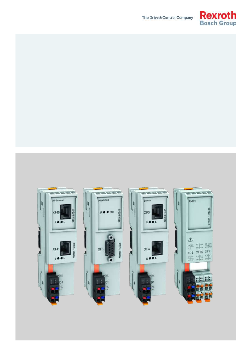
IndraControl
XFE 01.1
Extension Modules Profibus, RT-Ethernet, Sercos, CAN
Operating Instructions
R911345570
Edition 04

Bosch Rexroth AG Extension Modules Profibus, RT-
Ethernet, Sercos, CAN
Change Record
Edition Release
Notes
Date
Edition 01 2014-10 First edition
Edition 02 2016-08 CAN modules and Sercos modules supplemented
Edition 03 2016-10 Corrections
Edition 04 2017-02 Explosion protection notes and type plate supplemented
Copyright
© Bosch Rexroth AG 2017
This document, as well as the data, specifications and other information set
forth in it, are the exclusive property of Bosch Rexroth AG. It may not be reproduced or given to third parties without its consent.
Liability
The specified data is intended for product description purposes only and shall
not be deemed to be a guaranteed characteristic unless expressly stipulated in
the contract. All rights are reserved with respect to the content of this documentation and the availability of the product.
Editorial Department
Development Automation Systems Control Platform BoSc (MaKo/MePe)
RS-5a81c5d9d4f9f2ee0a6846a5006d8d2a-4-en-US-3

Extension Modules Profibus, RTEthernet, Sercos, CAN
Bosch Rexroth AG
Table of Contents
Table of Contents
Page
1 About this documentation..................................................................... 1
1.1 Overview on target groups and product phases.................................... 1
1.2 Scope..................................................................................................... 1
1.3 Related documents................................................................................ 2
1.4 Customer feedback................................................................................ 2
2 Product identification and scope of delivery......................................... 3
2.1 Product identification and type plate.................................................... 3
2.2 Scope of delivery................................................................................... 3
3 Use of the safety instructions................................................................ 4
3.1 Structure of the safety instructions....................................................... 4
3.2 Explaining signal words and safety alert symbol................................... 4
3.3 Symbols used......................................................................................... 5
3.4 Signal graphic explanation on the device.............................................. 5
4 Intended use.......................................................................................... 5
5 Spare parts, accessories and wear parts.............................................. 6
5.1 Connector 24 V...................................................................................... 6
5.2 Connector set for the CAN module........................................................ 6
5.3 Bus base module .................................................................................. 6
5.4 End clamp.............................................................................................. 6
5.5 Wear parts............................................................................................. 6
6 Ambient conditions................................................................................ 7
7 Technical data........................................................................................ 8
7.1 Voltage supply and current consumption.............................................. 8
8 Standards.............................................................................................. 9
8.1 Standards used...................................................................................... 9
8.2 CE marking........................................................................................... 10
8.2.1 Declaration of conformity.................................................................... 10
8.3 UL/CSA certified.................................................................................. 10
8.4 Explosion protection certification (XFE01.1-FB-03, XFE01.1-FB-20)... 11
8.4.1 Power matrix........................................................................................ 13
DOK-CONTRL-XFE**EXTMOD-IT04-EN-P
I

Bosch Rexroth AG
Table of Contents
Extension Modules Profibus, RT-
Ethernet, Sercos, CAN
Page
8.4.2 Standards used.................................................................................... 13
8.5 Marine and offshore certification (XFE01.1-FB-03, XFE01.1-FB-20).... 13
9 Interfaces............................................................................................. 14
10 Mounting, demounting and electric installationI................................. 16
10.1 Housing dimensions............................................................................. 16
10.2 Installation notes................................................................................. 16
10.3 Mounting.............................................................................................. 19
10.4 Demounting......................................................................................... 20
10.5 Electric installation.............................................................................. 21
10.5.1 External power supply unit ................................................................. 21
10.5.2 Voltage supply for the control and for the extension modules............ 23
10.5.3 24 V voltage supply.............................................................................. 24
11 Commissioning.................................................................................... 24
12 Device description............................................................................... 24
12.1 LEDs..................................................................................................... 25
12.1.1 LEDs on extension modules................................................................. 25
12.1.2 LED on XD1 plug.................................................................................. 26
13 Error causes and troubleshooting........................................................ 26
13.1 Error cases after commissioning the CAN module............................... 27
14 Maintenance........................................................................................ 28
14.1 General information............................................................................. 28
14.2 Regular maintenance tasks.................................................................. 28
15 Ordering information........................................................................... 29
15.1 Type code............................................................................................. 29
15.2 Accessories and spare parts................................................................ 30
16 Disposal............................................................................................... 30
16.1 General information............................................................................. 30
16.2 Return.................................................................................................. 30
16.3 Packaging............................................................................................. 30
17 Service and support............................................................................ 30
II
DOK-CONTRL-XFE**EXTMOD-IT04-EN-P

Extension Modules Profibus, RTEthernet, Sercos, CAN
Index.................................................................................................... 33
Bosch Rexroth AG
Table of Contents
Page
DOK-CONTRL-XFE**EXTMOD-IT04-EN-P
III

Bosch Rexroth AG Extension Modules Profibus, RT-
Ethernet, Sercos, CAN
IV
DOK-CONTRL-XFE**EXTMOD-IT04-EN-P
Presales Aftersales
Selection
Mounting
(assembly/installation)
Engineering
Commissioning
Operation
Decommissioning
Product
phases
Target
groups
Activities
Design engineer
Programmer
Technologist
Process
specialist
Select
Prepare
Design
Construct
Mechanic/
electrician
Unpack
Mount
Install
Programmer
Commissioning engineer
Parameterize
Program
Configure
Simulate
Technologist
Process specialist
Optimize
Test
Machine
operator
Maintenance
technician
Service
Operate
Maintain
Remove
faults
Create
the NC program
Mechanic/
electrician
Disposal company
Dismount
Dispose
Extension Modules Profibus, RTEthernet, Sercos, CAN
About this documentation
Bosch Rexroth AG
1 About this documentation
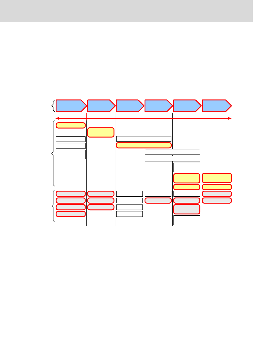
1.1 Overview on target groups and product phases
In the following illustration, the framed activities, product phases and target
groups refer to the present documentation.
Example: In the product phase "Mounting (assembly/installation)", the target
group "mechanic/electrician" can execute the activity "install" using this documentation.
Fig. 1-1:
tivities of the target group
This document instructs the technical staff of the machine manufacturer on how
to safely perform the mechanical and electrical installation and on how to commission the device.
Required qualification: Individual who is able to assess the tasks assigned and
to identify possible safety risks owing to qualification in the subject, knowledge
and experience. The individual should also be familiar with the standards and
regulations.
1.2
Scope
This document is valid for all variants of the modules, whose type code starts
with: XFE01.1-FB ...
The type code specifications are located on the type plate of the module. Also
refer to chapter 2 "Product identification and scope of delivery" on page 3.
DOK-CONTRL-XFE**EXTMOD-IT04-EN-P
Assigning the present documentation to the target groups, product phases and ac-
1/37

Bosch Rexroth AG
About this documentation
Extension Modules Profibus, RT-
Ethernet, Sercos, CAN
1.3 Related documents
Title Part number and document type
Rexroth IndraControl XM2x
Controls
Tab. 1-1: Related documents
R911340667
Operating Instructions
For related documents, go to the "Rexroth Media Directory" at http://
www.boschrexroth.com.
1.4 Customer feedback
Customer requests, comments or suggestions for improvement are of great importance to us. Please email your feedback on the documentations to Feed-
back.Documentation@boschrexroth.de. Directly insert comments in the elec-
tronic PDF document and send the PDF file to Bosch Rexroth.
2/37
DOK-CONTRL-XFE**EXTMOD-IT04-EN-P
U
0.6 A
Made in Germany
IndraControl S20
SN: 7260007123456BC
FD: 12W16
7260
FW: 101
N
N
I-V-C-B-T-V
Functional
Safety
Type
Approved
FI: 001
CERTIFIED
www.tuv.com
ID 10000000000
MNR: R911172531 -AA0
Bosch Rexroth AG, Bgm.-Dr.-Nebel-Str. 2
DE-97816 Lohr Hotline: +49 9352 405060
DC 24 V
I
Ex ec IIC Gc
IECEx TUR 16.0049 U
TÜV 16 ATEX 7949 U
II 3G
"IND.CONT.EQ"
32FB
16 channels
Wire Range 24-16
2700729
1 2 3 4 5 6 7 8 9
101112
13
14
15
16
17
1819
Extension Modules Profibus, RTEthernet, Sercos, CAN
Product identification and scope of delivery
Bosch Rexroth AG
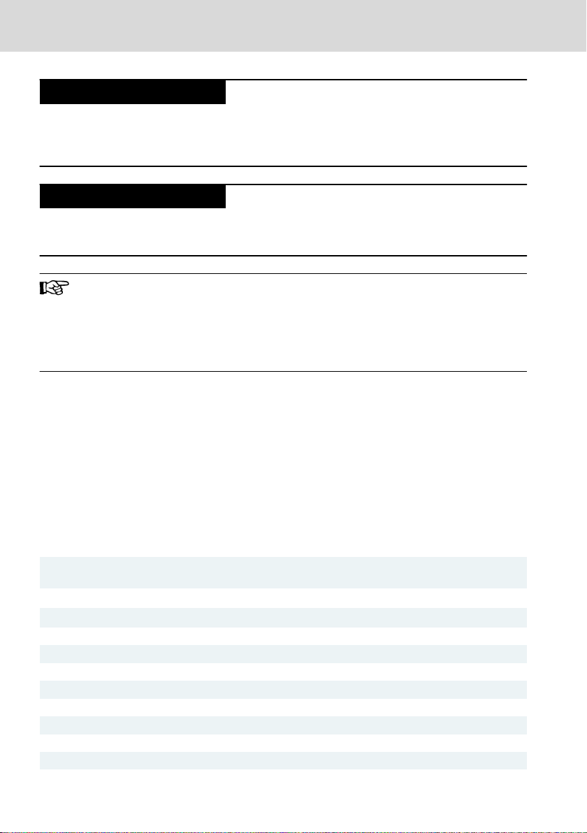
2 Product identification and scope of delivery
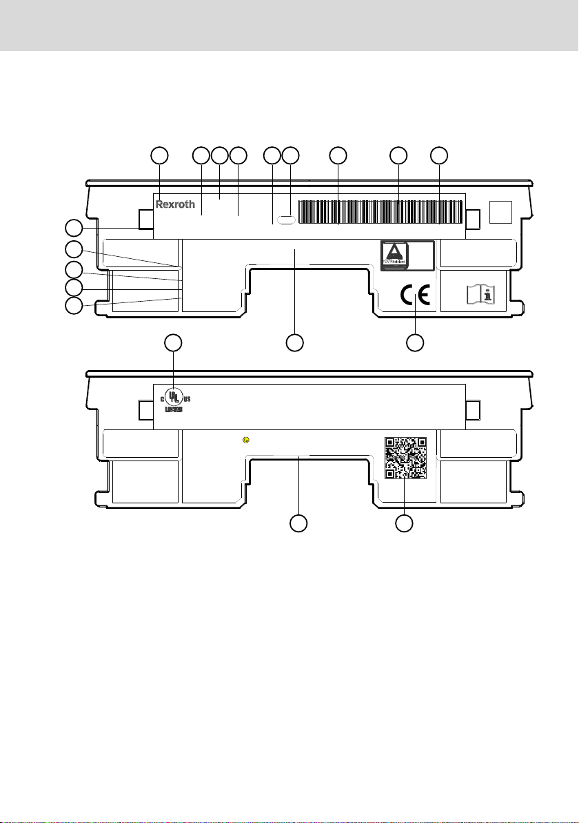
2.1 Product identification and type plate
1 Word mark
2 Part number
3 Device name
4 State of revision
5 Functional index
6 Plant number
7 Serial number
8 Serial number as barcode
9 Date of manufacture (yyWww)
10 CE conformity marking
Fig. 2-1: Exemplary type plate
2.2
Scope of delivery
● Extension module
● Bus base
● 24 V power connector XA-CN01
DOK-CONTRL-XFE**EXTMOD-IT04-EN-P
11 Company address
12 Underwriters Laboratories Inc. mark
13 Check digit
14 Nominal current
15 Nominal voltage
16 Manufacturing country
17 Software release
18 QR code
19 Explosion protection marking
3/37
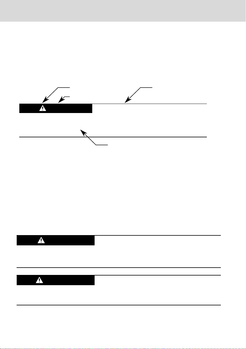
Burns and chemical burns due to wrong
battery treatment!
CAUTION
Safety alert symbol
Signal word
Consequences and
source of danger
Avoiding danger
Do not open the batteries and do not heat them over 80 °C.
DANGER
WARNING
Bosch Rexroth AG
Use of the safety instructions
● Safety instructions
Extension Modules Profibus, RT-
Ethernet, Sercos, CAN
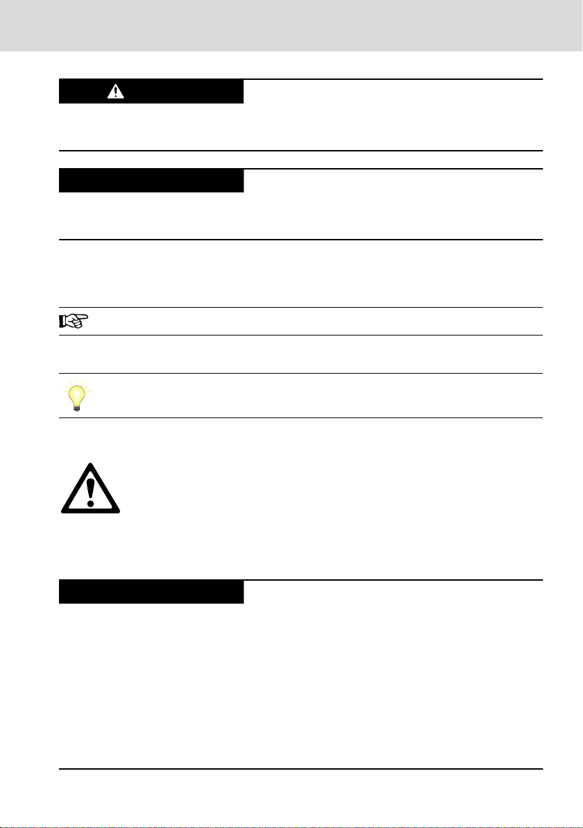
3 Use of the safety instructions
3.1 Structure of the safety instructions
The safety instructions are structured as follows:
Fig. 3-1: Structure of the safety instructions
3.2 Explaining signal words and safety alert symbol
The safety instructions in this documentation contain specific signal words (danger, warning, caution, notice) and, if necessary, a safety alert symbol (according
to ANSI Z535.6-2006).
The signal word is used to draw attention to the safety instruction and also provides information on the severity of the hazard.
The safety alert symbol (a triangle with an exclamation point), which precedes
the signal words danger,warning and caution is used to alert the reader to personal injury hazards.
In case of non-compliance with this safety instruction, death or serious injury
will occur.
In case of non-compliance with this safety instruction, death or serious injury
can occur.
4/37
DOK-CONTRL-XFE**EXTMOD-IT04-EN-P
CAUTION
NOTICE
krax
NOTICE
Extension Modules Profibus, RTEthernet, Sercos, CAN
In case of non-compliance with this safety instruction, minor or moderate injury
can occur.
In case of non-compliance with this safety instruction, material damage can occur.
Bosch Rexroth AG
Intended use
3.3 Symbols used
Hints are represented as follows:
This is an information.
Tips are represented as follows:
This is a tip.
3.4 Signal graphic explanation on the device
Prior to the installation and commissioning of the device, refer to the
device documentation.
4 Intended use
Risk of damaging the device if not expressly stated accessories, mounting parts and other components, cables, lines and software and firmware are used.
The IndraControl extension modules may exclusively be used with the accessories and add-on components specified in this documentation. Components that
are not expressly mentioned must neither be attached nor connected. The same
applies to cables and lines.
Only to be operated with the component configurations and combinations expressly defined and with the software and firmware specified in the corresponding functional description.
DOK-CONTRL-XFE**EXTMOD-IT04-EN-P
5/37

Bosch Rexroth AG
Spare parts, accessories and wear parts
The IndraControl extension modules can be used for complex connections to
controls that cannot be operated at the S20 bus, such as interface modules to
Profinet, Profibus, CAN and Sercos or Safety connection.
The IndraControl extension modules may only be operated under the mounting
and installation conditions, the position and the ambient conditions (temperature, degree of protection, humidity, EMC etc.) specified in this documentation.
5
Spare parts, accessories and wear parts
Extension Modules Profibus, RT-
Ethernet, Sercos, CAN
5.1 Connector 24 V
Ordering code Part number Description
XA-CN01 R911173741 24 V plug
Tab. 5-1: Connector, 24 V
5.2 Connector set for the CAN module
Ordering code Part number Description
S20-CNS 2S-O/D/UI/E1/E2 R911173804 Connector set for the 24 V module and the
Tab. 5-2: Connector set CAN module
CAN module
5.3 Bus base module
Ordering code Part number Description
XA-BS11 R911173772 Bus base module for extension modules
Tab. 5-3: Bus base module for extension bus
5.4 End clamp
Ordering code Part number Description
SUP-M01-ENDHALTER R911170685 2 pieces of snap-on end brackets for 35
Tab. 5-4: End clamp
mm NS 35/7.5 or NS 35/15 carrier plate;
width: 9.5 mm
5.5 Wear parts
There are no wear parts in the extension modules.
6/37
DOK-CONTRL-XFE**EXTMOD-IT04-EN-P

NOTICE
Extension Modules Profibus, RTEthernet, Sercos, CAN
Bosch Rexroth AG
Ambient conditions
6 Ambient conditions
In operation
Ambient temperature in oper-
ation
Ambient temperature during
storage and transport
Permitted air humidity 5 % to 95 % acc. to DIN EN 61131-2
Operating altitude Up to 3,000 m above sea level acc. to DIN 61010-1
Mechanical strength
①
Overvoltage category 2
Contamination level 2
Degree of protection IP20 acc. to DIN EN 60 529
Protection class III, DIN EN 61010-2-201
① The vibration stress specifications assume the use of industrial-suited RJ45 plug connec-
tions. The "Industrial RJ45 plug" of the company Yamaichi is recommended (Y-ConPlug-41). The cables are available as accessories (RKB0020). To protect against vibration,
secure the cables with a short distance (< 20 cm).
Tab. 6-1: Ambient conditions
Up to 2,000 m:
-25 °C to +60 °C
2,000 m to 3,000 m:
-25 °C to +55 °C
–40 °C to +85 °C
Condensation not allowed
Vibration stress:
● Oscillations, sinusoidal in all three axes acc. to DIN EN 60068-2-6
5-9 Hz with an amplitude of 3.5 mm
9-150 Hz with 5 g peak acceleration
● Broadband noise acc. to DIN EN 60068-2-64
5-20-150 Hz with 0.572 g, 5 h per axis
Shock stress: Shock resistance in all three axes acc. to DIN EN
60068-2-27
11 ms semi-sinusoidal 30 g
Failure of the product due to contaminated air
● The ambient air must not contain acids, alkaline solutions, corrosive agents,
salts, metal vapors and other electrically conductive contaminants in high
concentrations
● Housing and installation compartments must at least comply with the degree
of protection IP 54 according to DIN EN 60529
DOK-CONTRL-XFE**EXTMOD-IT04-EN-P
7/37
NOTICE
NOTICE
Bosch Rexroth AG
Technical data
Defective product due to gases jeopardizing
functions
Due to the risk of corrosion, avoid sulphurous gases (e.g. sulphur dioxide (SO2)
and hydrogen suphide (H2S)). The product is not resistant against these gases.
Failure of the product due to overheating
To avoid overheating and a trouble-free operation of the product, the ambient air
has to circulate. Also refer to chapter 10.2 "Installation notes" on page 16
This is a product that corresponds to the limit values of the emitted
interference of class A (industrial environments), but not of class B
(residential area and small enterprises).
When using the product in residential areas or small enterprises, the
operator has to take actions to prevent radio interferences (also refer to DIN EN 55022).
7
Technical data
Extension Modules Profibus, RT-
Ethernet, Sercos, CAN
Weight 0.120 kg
Degree of protection IP 20 acc. to DIN EN 60 529
Tab. 7-1: Technical data
7.1 Voltage supply and current consumption
The following specifications include the values acc. to EN 61131-2.
Infeed U
L
Maximum voltage range allowed 18 V DC to 31.2 V DC (incl. all tolerances and rip-
Current consumption from U
Power consumption from U
Reverse voltage protection of the supply voltage Diode
Fuse protection Internal protective fuse, 4 A
Transient protection Present, suppressor diodes
Voltage dips at current supply interfaces Up to 10 ms without impairment
Electrical isolation and isolation of the voltage ranges
Profibus extension module
24 V supply with FE to XF8 845 V AC, 50 Hz, 1 min
8/37
L
L
24 V DC PELV/SELV (safety extra-low voltage)
ple)
0.2 A max.
4.8 W max.
DOK-CONTRL-XFE**EXTMOD-IT04-EN-P
 Loading...