

Bosch XFE 01.1-FB-01, XFE 01.1-FB-20, XFE 01.1-FB-03, XFE 01.1-FB-10 Operating Instructions Manual
Page 1
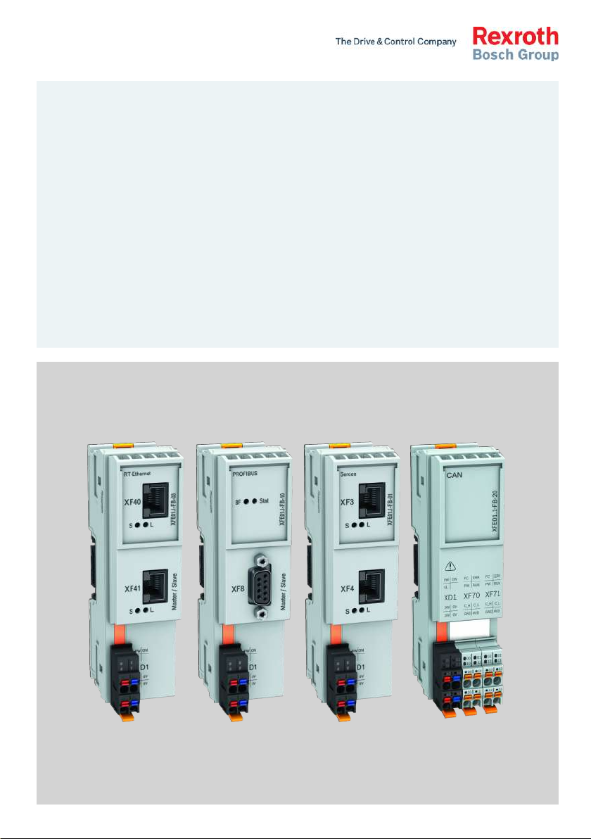
IndraControl
XFE 01.1
Extension Modules Profibus, RT-Ethernet, Sercos, CAN
Operating Instructions
R911345570
Edition 04
Page 2

Bosch Rexroth AG Extension Modules Profibus, RT-
Ethernet, Sercos, CAN
Change Record
Edition Release
Notes
Date
Edition 01 2014-10 First edition
Edition 02 2016-08 CAN modules and Sercos modules supplemented
Edition 03 2016-10 Corrections
Edition 04 2017-02 Explosion protection notes and type plate supplemented
Copyright
© Bosch Rexroth AG 2017
This document, as well as the data, specifications and other information set
forth in it, are the exclusive property of Bosch Rexroth AG. It may not be reproduced or given to third parties without its consent.
Liability
The specified data is intended for product description purposes only and shall
not be deemed to be a guaranteed characteristic unless expressly stipulated in
the contract. All rights are reserved with respect to the content of this documentation and the availability of the product.
Editorial Department
Development Automation Systems Control Platform BoSc (MaKo/MePe)
RS-5a81c5d9d4f9f2ee0a6846a5006d8d2a-4-en-US-3
Page 3

Extension Modules Profibus, RTEthernet, Sercos, CAN
Bosch Rexroth AG
Table of Contents
Table of Contents
Page
1 About this documentation..................................................................... 1
1.1 Overview on target groups and product phases.................................... 1
1.2 Scope..................................................................................................... 1
1.3 Related documents................................................................................ 2
1.4 Customer feedback................................................................................ 2
2 Product identification and scope of delivery......................................... 3
2.1 Product identification and type plate.................................................... 3
2.2 Scope of delivery................................................................................... 3
3 Use of the safety instructions................................................................ 4
3.1 Structure of the safety instructions....................................................... 4
3.2 Explaining signal words and safety alert symbol................................... 4
3.3 Symbols used......................................................................................... 5
3.4 Signal graphic explanation on the device.............................................. 5
4 Intended use.......................................................................................... 5
5 Spare parts, accessories and wear parts.............................................. 6
5.1 Connector 24 V...................................................................................... 6
5.2 Connector set for the CAN module........................................................ 6
5.3 Bus base module .................................................................................. 6
5.4 End clamp.............................................................................................. 6
5.5 Wear parts............................................................................................. 6
6 Ambient conditions................................................................................ 7
7 Technical data........................................................................................ 8
7.1 Voltage supply and current consumption.............................................. 8
8 Standards.............................................................................................. 9
8.1 Standards used...................................................................................... 9
8.2 CE marking........................................................................................... 10
8.2.1 Declaration of conformity.................................................................... 10
8.3 UL/CSA certified.................................................................................. 10
8.4 Explosion protection certification (XFE01.1-FB-03, XFE01.1-FB-20)... 11
8.4.1 Power matrix........................................................................................ 13
DOK-CONTRL-XFE**EXTMOD-IT04-EN-P
I
Page 4

Bosch Rexroth AG
Table of Contents
Extension Modules Profibus, RT-
Ethernet, Sercos, CAN
Page
8.4.2 Standards used.................................................................................... 13
8.5 Marine and offshore certification (XFE01.1-FB-03, XFE01.1-FB-20).... 13
9 Interfaces............................................................................................. 14
10 Mounting, demounting and electric installationI................................. 16
10.1 Housing dimensions............................................................................. 16
10.2 Installation notes................................................................................. 16
10.3 Mounting.............................................................................................. 19
10.4 Demounting......................................................................................... 20
10.5 Electric installation.............................................................................. 21
10.5.1 External power supply unit ................................................................. 21
10.5.2 Voltage supply for the control and for the extension modules............ 23
10.5.3 24 V voltage supply.............................................................................. 24
11 Commissioning.................................................................................... 24
12 Device description............................................................................... 24
12.1 LEDs..................................................................................................... 25
12.1.1 LEDs on extension modules................................................................. 25
12.1.2 LED on XD1 plug.................................................................................. 26
13 Error causes and troubleshooting........................................................ 26
13.1 Error cases after commissioning the CAN module............................... 27
14 Maintenance........................................................................................ 28
14.1 General information............................................................................. 28
14.2 Regular maintenance tasks.................................................................. 28
15 Ordering information........................................................................... 29
15.1 Type code............................................................................................. 29
15.2 Accessories and spare parts................................................................ 30
16 Disposal............................................................................................... 30
16.1 General information............................................................................. 30
16.2 Return.................................................................................................. 30
16.3 Packaging............................................................................................. 30
17 Service and support............................................................................ 30
II
DOK-CONTRL-XFE**EXTMOD-IT04-EN-P
Page 5

Extension Modules Profibus, RTEthernet, Sercos, CAN
Index.................................................................................................... 33
Bosch Rexroth AG
Table of Contents
Page
DOK-CONTRL-XFE**EXTMOD-IT04-EN-P
III
Page 6

Bosch Rexroth AG Extension Modules Profibus, RT-
Ethernet, Sercos, CAN
IV
DOK-CONTRL-XFE**EXTMOD-IT04-EN-P
Page 7
Presales Aftersales
Selection
Mounting
(assembly/installation)
Engineering
Commissioning
Operation
Decommissioning
Product
phases
Target
groups
Activities
Design engineer
Programmer
Technologist
Process
specialist
Select
Prepare
Design
Construct
Mechanic/
electrician
Unpack
Mount
Install
Programmer
Commissioning engineer
Parameterize
Program
Configure
Simulate
Technologist
Process specialist
Optimize
Test
Machine
operator
Maintenance
technician
Service
Operate
Maintain
Remove
faults
Create
the NC program
Mechanic/
electrician
Disposal company
Dismount
Dispose
Extension Modules Profibus, RTEthernet, Sercos, CAN
About this documentation
Bosch Rexroth AG
1 About this documentation
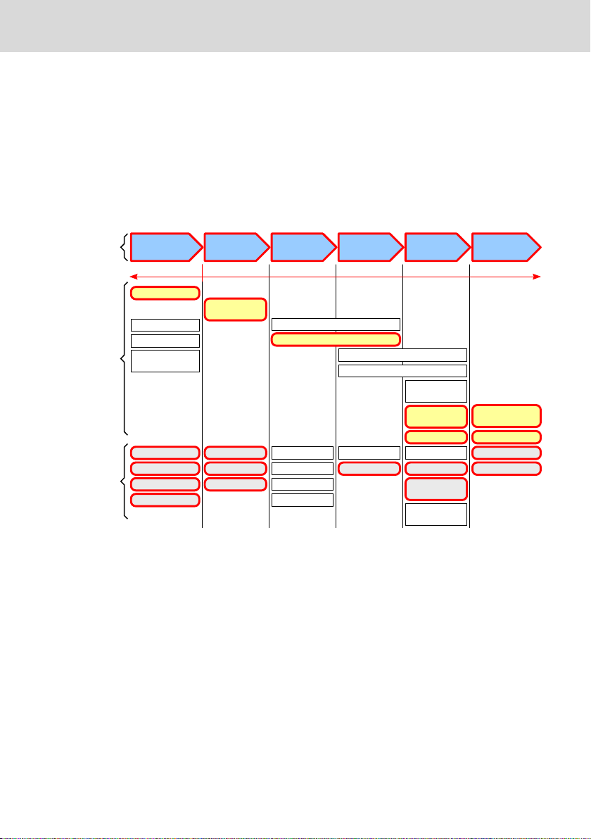
1.1 Overview on target groups and product phases
In the following illustration, the framed activities, product phases and target
groups refer to the present documentation.
Example: In the product phase "Mounting (assembly/installation)", the target
group "mechanic/electrician" can execute the activity "install" using this documentation.
Fig. 1-1:
tivities of the target group
This document instructs the technical staff of the machine manufacturer on how
to safely perform the mechanical and electrical installation and on how to commission the device.
Required qualification: Individual who is able to assess the tasks assigned and
to identify possible safety risks owing to qualification in the subject, knowledge
and experience. The individual should also be familiar with the standards and
regulations.
1.2
Scope
This document is valid for all variants of the modules, whose type code starts
with: XFE01.1-FB ...
The type code specifications are located on the type plate of the module. Also
refer to chapter 2 "Product identification and scope of delivery" on page 3.
DOK-CONTRL-XFE**EXTMOD-IT04-EN-P
Assigning the present documentation to the target groups, product phases and ac-
1/37
Page 8

Bosch Rexroth AG
About this documentation
Extension Modules Profibus, RT-
Ethernet, Sercos, CAN
1.3 Related documents
Title Part number and document type
Rexroth IndraControl XM2x
Controls
Tab. 1-1: Related documents
R911340667
Operating Instructions
For related documents, go to the "Rexroth Media Directory" at http://
www.boschrexroth.com.
1.4 Customer feedback
Customer requests, comments or suggestions for improvement are of great importance to us. Please email your feedback on the documentations to Feed-
back.Documentation@boschrexroth.de. Directly insert comments in the elec-
tronic PDF document and send the PDF file to Bosch Rexroth.
2/37
DOK-CONTRL-XFE**EXTMOD-IT04-EN-P
Page 9
U
0.6 A
Made in Germany
IndraControl S20
SN: 7260007123456BC
FD: 12W16
7260
FW: 101
N
N
I-V-C-B-T-V
Functional
Safety
Type
Approved
FI: 001
CERTIFIED
www.tuv.com
ID 10000000000
MNR: R911172531 -AA0
Bosch Rexroth AG, Bgm.-Dr.-Nebel-Str. 2
DE-97816 Lohr Hotline: +49 9352 405060
DC 24 V
I
Ex ec IIC Gc
IECEx TUR 16.0049 U
TÜV 16 ATEX 7949 U
II 3G
"IND.CONT.EQ"
32FB
16 channels
Wire Range 24-16
2700729
1 2 3 4 5 6 7 8 9
101112
13
14
15
16
17
1819
Extension Modules Profibus, RTEthernet, Sercos, CAN
Product identification and scope of delivery
Bosch Rexroth AG
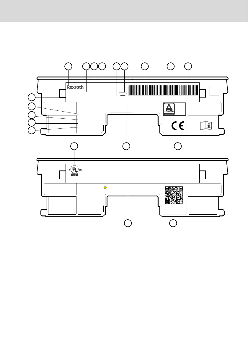
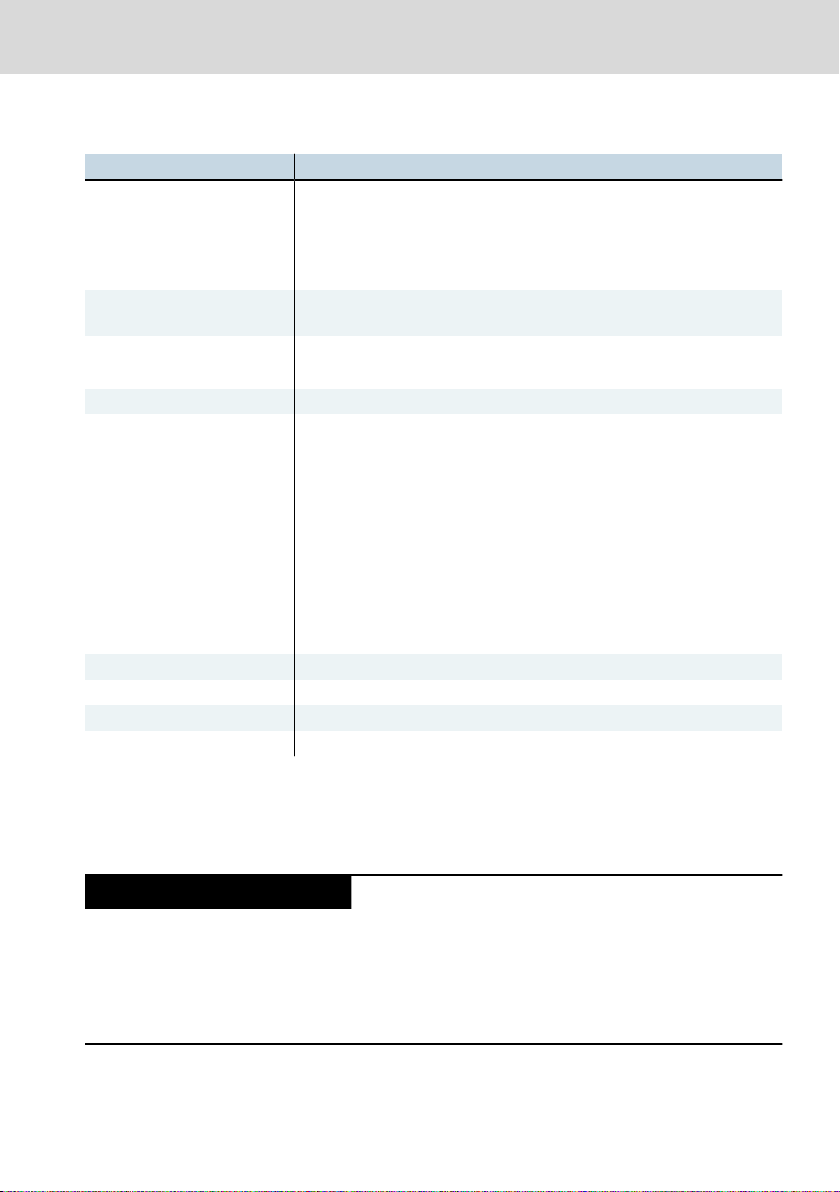
2 Product identification and scope of delivery
2.1 Product identification and type plate
1 Word mark
2 Part number
3 Device name
4 State of revision
5 Functional index
6 Plant number
7 Serial number
8 Serial number as barcode
9 Date of manufacture (yyWww)
10 CE conformity marking
Fig. 2-1: Exemplary type plate
2.2
Scope of delivery
● Extension module
● Bus base
● 24 V power connector XA-CN01
DOK-CONTRL-XFE**EXTMOD-IT04-EN-P
11 Company address
12 Underwriters Laboratories Inc. mark
13 Check digit
14 Nominal current
15 Nominal voltage
16 Manufacturing country
17 Software release
18 QR code
19 Explosion protection marking
3/37
Page 10
Burns and chemical burns due to wrong
battery treatment!
CAUTION
Safety alert symbol
Signal word
Consequences and
source of danger
Avoiding danger
Do not open the batteries and do not heat them over 80 °C.
DANGER
WARNING
Bosch Rexroth AG
Use of the safety instructions
● Safety instructions
Extension Modules Profibus, RT-
Ethernet, Sercos, CAN
3 Use of the safety instructions
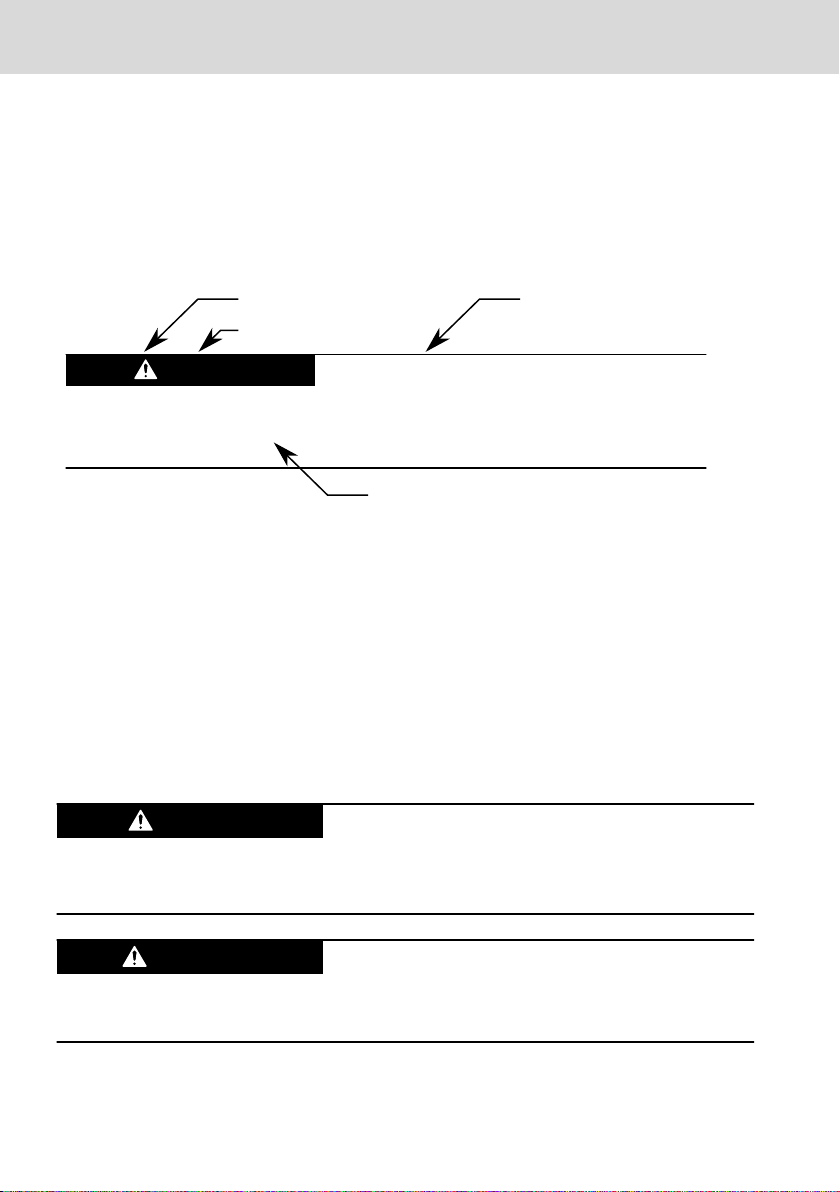
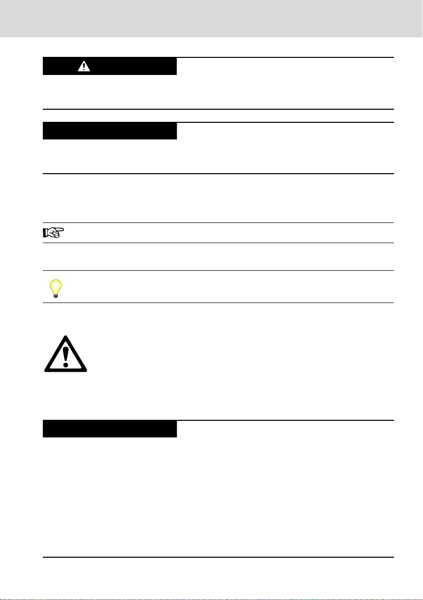
3.1 Structure of the safety instructions
The safety instructions are structured as follows:
Fig. 3-1: Structure of the safety instructions
3.2 Explaining signal words and safety alert symbol
The safety instructions in this documentation contain specific signal words (danger, warning, caution, notice) and, if necessary, a safety alert symbol (according
to ANSI Z535.6-2006).
The signal word is used to draw attention to the safety instruction and also provides information on the severity of the hazard.
The safety alert symbol (a triangle with an exclamation point), which precedes
the signal words danger,warning and caution is used to alert the reader to personal injury hazards.
In case of non-compliance with this safety instruction, death or serious injury
will occur.
In case of non-compliance with this safety instruction, death or serious injury
can occur.
4/37
DOK-CONTRL-XFE**EXTMOD-IT04-EN-P
Page 11
CAUTION
NOTICE
krax
NOTICE
Extension Modules Profibus, RTEthernet, Sercos, CAN
In case of non-compliance with this safety instruction, minor or moderate injury
can occur.
In case of non-compliance with this safety instruction, material damage can occur.
Bosch Rexroth AG
Intended use
3.3 Symbols used
Hints are represented as follows:
This is an information.
Tips are represented as follows:
This is a tip.
3.4 Signal graphic explanation on the device
Prior to the installation and commissioning of the device, refer to the
device documentation.
4 Intended use
Risk of damaging the device if not expressly stated accessories, mounting parts and other components, cables, lines and software and firmware are used.
The IndraControl extension modules may exclusively be used with the accessories and add-on components specified in this documentation. Components that
are not expressly mentioned must neither be attached nor connected. The same
applies to cables and lines.
Only to be operated with the component configurations and combinations expressly defined and with the software and firmware specified in the corresponding functional description.
DOK-CONTRL-XFE**EXTMOD-IT04-EN-P
5/37
Page 12

Bosch Rexroth AG
Spare parts, accessories and wear parts
The IndraControl extension modules can be used for complex connections to
controls that cannot be operated at the S20 bus, such as interface modules to
Profinet, Profibus, CAN and Sercos or Safety connection.
The IndraControl extension modules may only be operated under the mounting
and installation conditions, the position and the ambient conditions (temperature, degree of protection, humidity, EMC etc.) specified in this documentation.
5
Spare parts, accessories and wear parts
Extension Modules Profibus, RT-
Ethernet, Sercos, CAN
5.1 Connector 24 V
Ordering code Part number Description
XA-CN01 R911173741 24 V plug
Tab. 5-1: Connector, 24 V
5.2 Connector set for the CAN module
Ordering code Part number Description
S20-CNS 2S-O/D/UI/E1/E2 R911173804 Connector set for the 24 V module and the
Tab. 5-2: Connector set CAN module
CAN module
5.3 Bus base module
Ordering code Part number Description
XA-BS11 R911173772 Bus base module for extension modules
Tab. 5-3: Bus base module for extension bus
5.4 End clamp
Ordering code Part number Description
SUP-M01-ENDHALTER R911170685 2 pieces of snap-on end brackets for 35
Tab. 5-4: End clamp
mm NS 35/7.5 or NS 35/15 carrier plate;
width: 9.5 mm
5.5 Wear parts
There are no wear parts in the extension modules.
6/37
DOK-CONTRL-XFE**EXTMOD-IT04-EN-P
Page 13
NOTICE
Extension Modules Profibus, RTEthernet, Sercos, CAN
Bosch Rexroth AG
Ambient conditions
6 Ambient conditions
In operation
Ambient temperature in oper-
ation
Ambient temperature during
storage and transport
Permitted air humidity 5 % to 95 % acc. to DIN EN 61131-2
Operating altitude Up to 3,000 m above sea level acc. to DIN 61010-1
Mechanical strength
①
Overvoltage category 2
Contamination level 2
Degree of protection IP20 acc. to DIN EN 60 529
Protection class III, DIN EN 61010-2-201
① The vibration stress specifications assume the use of industrial-suited RJ45 plug connec-
tions. The "Industrial RJ45 plug" of the company Yamaichi is recommended (Y-ConPlug-41). The cables are available as accessories (RKB0020). To protect against vibration,
secure the cables with a short distance (< 20 cm).
Tab. 6-1: Ambient conditions
Up to 2,000 m:
-25 °C to +60 °C
2,000 m to 3,000 m:
-25 °C to +55 °C
–40 °C to +85 °C
Condensation not allowed
Vibration stress:
● Oscillations, sinusoidal in all three axes acc. to DIN EN 60068-2-6
5-9 Hz with an amplitude of 3.5 mm
9-150 Hz with 5 g peak acceleration
● Broadband noise acc. to DIN EN 60068-2-64
5-20-150 Hz with 0.572 g, 5 h per axis
Shock stress: Shock resistance in all three axes acc. to DIN EN
60068-2-27
11 ms semi-sinusoidal 30 g
Failure of the product due to contaminated air
● The ambient air must not contain acids, alkaline solutions, corrosive agents,
salts, metal vapors and other electrically conductive contaminants in high
concentrations
● Housing and installation compartments must at least comply with the degree
of protection IP 54 according to DIN EN 60529
DOK-CONTRL-XFE**EXTMOD-IT04-EN-P
7/37
Page 14
NOTICE
NOTICE
Bosch Rexroth AG
Technical data
Defective product due to gases jeopardizing
functions
Due to the risk of corrosion, avoid sulphurous gases (e.g. sulphur dioxide (SO2)
and hydrogen suphide (H2S)). The product is not resistant against these gases.
Failure of the product due to overheating
To avoid overheating and a trouble-free operation of the product, the ambient air
has to circulate. Also refer to chapter 10.2 "Installation notes" on page 16
This is a product that corresponds to the limit values of the emitted
interference of class A (industrial environments), but not of class B
(residential area and small enterprises).
When using the product in residential areas or small enterprises, the
operator has to take actions to prevent radio interferences (also refer to DIN EN 55022).
7
Technical data
Extension Modules Profibus, RT-
Ethernet, Sercos, CAN
Weight 0.120 kg
Degree of protection IP 20 acc. to DIN EN 60 529
Tab. 7-1: Technical data
7.1 Voltage supply and current consumption
The following specifications include the values acc. to EN 61131-2.
Infeed U
L
Maximum voltage range allowed 18 V DC to 31.2 V DC (incl. all tolerances and rip-
Current consumption from U
Power consumption from U
Reverse voltage protection of the supply voltage Diode
Fuse protection Internal protective fuse, 4 A
Transient protection Present, suppressor diodes
Voltage dips at current supply interfaces Up to 10 ms without impairment
Electrical isolation and isolation of the voltage ranges
Profibus extension module
24 V supply with FE to XF8 845 V AC, 50 Hz, 1 min
8/37
L
L
24 V DC PELV/SELV (safety extra-low voltage)
ple)
0.2 A max.
4.8 W max.
DOK-CONTRL-XFE**EXTMOD-IT04-EN-P
Page 15

NOTICE
Extension Modules Profibus, RTEthernet, Sercos, CAN
RT Ethernet extension module
24 V supply with FE to XF40 845 V AC, 50 Hz, 1 min
24 V supply with FE to XF41 845 V AC, 50 Hz, 1 min
XF40 to XF41 845 V AC, 50 Hz, 1 min
Sercos extension module
24 V supply with FE to XF3 845 V AC, 50 Hz, 1 min
24 V supply with FE to XF4 845 V AC, 50 Hz, 1 min
XF3 to XF4 845 V AC, 50 Hz, 1 min
CAN extension module
24 V supply to XF70 845 V AC, 50 Hz, 1 min
24 V supply to XF71 845 V AC, 50 Hz, 1 min
24 V supply to FE 845 V AC, 50 Hz, 1 min
XF70 to FE 845 V AC, 50 Hz, 1 min
XF71 to FE 845 V AC, 50 Hz, 1 min
XF70 to XF71 845 V AC, 50 Hz, 1 min
Tab. 7-2: Operating voltage and current consumption
Electronic damage due to polarity reversal or
due to a nominal current that is too low
The power supply unit has to be able to deliver the quadruple nominal current of
the protective fuse to ensure that the fuse reliably triggers in case of an error.
Bosch Rexroth AG
Standards
8
Standards
The products have been developed according to the German edition of the
standards published at the time of product engineering.
8.1
Standards used
Standard Meaning Edition
IEC 60204-1 Electrical equipment of machines 2007
IEC 61131-2 Programmable controllers 2008
IEC 60529 Degrees of protection provided by enclosures (IP Code) 2014
IEC 61010-2-201 Safety requirements for electrical equipment for measure-
ment, control and laboratory use
UL 61010-2-201 Safety requirements for electrical equipment for measure-
ment, control and laboratory use
Tab. 8-1: Standards used
DOK-CONTRL-XFE**EXTMOD-IT04-EN-P
2014
2014
9/37
Page 16

Bosch Rexroth AG
Standards
Extension Modules Profibus, RT-
Ethernet, Sercos, CAN
8.2 CE marking
8.2.1 Declaration of conformity
The electronic products described in the present operating instructions comply
with the requirements and the target of the following EU directive and with the
following harmonized European standards:
EMC directive 2014/30/EC
The electronic products described in the present operating instructions are in-
tended for use in industrial environments and comply with the following requirements:
Standard Title Edition
DIN EN 61000-6-4 Electromagnetic compatibility (EMC)
Part 6-4: Generic standards – Emission standard for industrial environments
DIN EN 61000-6-2 Electromagnetic compatibility (EMC)
Part 6-2: Generic standards – Immunity for industrial environments
Tab. 8-2: Standards for electromagnetic compatibility (EMC)
September
2011
March 2006
Loss of CE conformity due to modifications at the device.
CE marking applies only to the device upon delivery. After modifying
the device, verify the CE conformity.
8.3 UL/CSA certified
The devices are certified acc. to
● UL 61010-2-201 (Industrial Control Equipment) and
● C22.2 no. 142-M1987 (CSA)
However, there can be combinations or extension stages with a limited or missing certification. Thus, verify the registration according to the UL marking on the
device.
Loss of UL/CSA conformity due to modifications at the device.
UL and CSA marking applies only to the device upon delivery. After
modifying the device, verify the UL and the CSA conformity.
10/37
DOK-CONTRL-XFE**EXTMOD-IT04-EN-P
Page 17

II 3G
Ex ec IIC Gc
TÜV 16 ATEX 7949 U
IECEx TUR 16.0049 U
Extension Modules Profibus, RTEthernet, Sercos, CAN
Bosch Rexroth AG
Standards
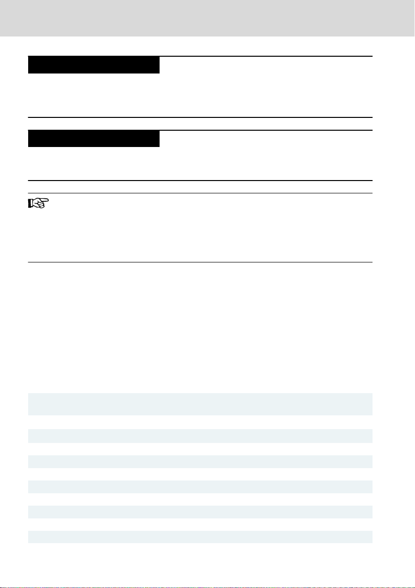
8.4 Explosion protection certification (XFE01.1-FB-03, XFE01.1FB-20)
Ex Explosion protection label
II Equipment group II: Explosive gas
3G Equipment category 3: Explosive at-
Ex Explosion protection label
ec Type of protection "Increased safety"
IIC Gas group IIC, hydrogen
Fig. 8-1: Exemplary type plate
atmospheres
mosphere (zone 2)
Gc Equipment protection level (EPL),
TÜV... ATEX EU type examination certificate
IECEx... IECEx certificate number
...U Component marking
rare and momentary explosive atmosphere (zone 2): Flammable
gases, vapors, mists
The approval numbers given on the type plate are marked at the end with an "X"
for devices and a "U" for components. "X" indicates special conditions to be observed together with the safety and health regulations given in the standards.
"U" indicates a component (Ex component) that may not be used on its own.
DOK-CONTRL-XFE**EXTMOD-IT04-EN-P
11/37
Page 18

DANGER
DANGER
Bosch Rexroth AG
Standards
Observe the following special conditions for a safe operation of the
devices and components:
● The explosion protection approval applies only to the components
XFE01.1-FB-03 and XFE01.1-FB-20.
● The explosion protection approval is only valid if the devices and
components approved by Bosch Rexroth are used as intended, refer to chapter 4 "Intended use" on page 5.
● The components may only be used together with the devices and
accessories approved by Bosch Rexroth. Otherwise, the explosion
protection approval does not apply.
● In case of unintended modifications at the device or at the com-
ponents, the explosion protection approval does also not apply.
For maintenance and troubleshooting, refer to chapter 14 "Main-
tenance" on page 28 and chapter 13 "Error causes and troubleshooting" on page 26.
● The components may only be used in an area with the minimum
pollution degree 2 as defined in IEC 60991-1.
● For the permitted ambient temperature range, refer to chapter 6
"Ambient conditions" on page 7.
● The components may only be installed in a housing (control cabi-
net) providing at least an ingress protection of IP54 in compliance
with IEC 60079-0.
● Take suitable actions to ensure that the supply voltage outside the
device or the component is always within the permitted voltage
range (±10%) acc. to EN 60079-0.
● Maintenance and repair work may only be carried out by the certi-
fied Rexroth service.
● Always store and transport the device or the component in the
original package.
Extension Modules Profibus, RT-
Ethernet, Sercos, CAN
Explosion hazard
Working at the components is only permitted if there is no explosive atmosphere.
Explosion hazard when exceeding or falling below the ambient temperature
Do not exceed the ambient temperature permitted, refer to chapter 6 "Ambient
conditions" on page 7
12/37
DOK-CONTRL-XFE**EXTMOD-IT04-EN-P
Page 19

Extension Modules Profibus, RTEthernet, Sercos, CAN
Bosch Rexroth AG
Standards
8.4.1 Power matrix
Components Max. internal current consumption Max. internal power consumption
XFE01.1-FB-03
200 mA 4.8 W
R911173397
XFE01.1-FB-20
200 mA 4.8 W
R911173957
Tab. 8-3: Power matrix of the approved components
If the housing surface (control cabinet) is 1m2, up to 87 W of internal power consumption of the individual devices and components
are permitted.
8.4.2 Standards used
Standard Title
EN 60079-0:2012 + A11:2013
IEC 60079-0:2011, modified + Corr.:2012
+ Corr.:2013
EN 60079-7:2015
IEC 60079-7:2015
Explosive atmospheres –
Part 0: Equipment –
General requirements
Explosive atmospheres –
Part 7: Equipment protection by increased safety "e"
Tab. 8-4: Standard used for explosion protection
8.5 Marine and offshore certification (XFE01.1-FB-03, XFE01.1FB-20)
The extension modules XFE01.1-FB-03, XFE01.1-FB-20 are suitable for the use in
marine and offshore applications and were approved by the following certification organizations:
● DNV-GL Det Norske Veritas, Germanischer Lloyd DCTC_30826-001
● ABS American Bureau of Shipping DCTC_30826-002
● RINA Registro Italiano Navale DCTC_30826-003
● LR Lloyd's Register DCTC_30826-004
● BV Bureau Veritas DCTC_30826-005
● BSH Bundesamt für Seeschifffahrt und Hydrographie DCTC 30826-006
For more information, refer to
gation/VorNavi.cfm?PageID=p669155.
DOK-CONTRL-XFE**EXTMOD-IT04-EN-P
www.boschrexroth.com/dcc/Vornavi-
13/37
Page 20

3
2
1
4
1
5
6
7 8
9
NOTICE
Bosch Rexroth AG
Interfaces
9 Interfaces
Fig. 9-1: Interfaces of the extension modules
Extension Modules Profibus, RT-
Ethernet, Sercos, CAN
Attaching and detaching connections under
voltage can damage the extension modules and
the control!
Switch off the supply voltage before attaching or detaching any connections!
No.
① XD1 Voltage supply 4-pin (4-wire)
RT Ethernet extension module
② XF41 Ethernet RJ45 socket
③ XF40 Ethernet RJ45 socket
Profibus extension module
④ XF8 Profibus D-SUB socket
Sercos extension module
14/37
Name Connection type Connector type
(Integrated)
8-pin
8-pin
9-pin
DOK-CONTRL-XFE**EXTMOD-IT04-EN-P
Mating connector and
cable
(From outside)
RJ45 plug
8-pin
RJ45 plug
8-pin
D-SUB plug
9-pin
Page 21

Extension Modules Profibus, RTEthernet, Sercos, CAN
Bosch Rexroth AG
Interfaces
No. Name Connection type Connector type
(Integrated)
Mating connector and
cable
(From outside)
⑤ XF3 Ethernet RJ45 socket
8-pin
⑥ XF4 Ethernet RJ45 socket
8-pin
RJ45 plug
8-pin
RJ45 plug
8-pin
CAN extension module
⑦ XF70 CAN CAN cable (4-pin) CAN cable (4-pin)
⑧ XF71 CAN CAN cable (4-pin) CAN cable (4-pin)
⑨ Fallback pushbutton
Tab. 9-1: Interfaces of the extension modules
Connector contact
Signal Function
XF70 or XF71
00 or 02 C_H CAN_H signal
01 or 03 C_L CAN_L signal
10 or 12 GND CAN ground
11 or 13 WID Adding the termination resistor to the CAN network
The resistor is enabled by connecting the plug contacts 10 (CAN
GND) and 11 (WID) or 12 (CAN GND) and 13 (WID).
Tab. 9-2: Pin assignment of XF70 and XF71
Plug name S20 plug
Connection method Spring-cage connection in direct plug-in technolo-
gy
Conductor cross-section
Rigid or flexible 0.2 mm2 to 1.5 mm
2
Conductor cross-section AWG 24 to 16
Tab. 9-3: Connection data of XF70 and XF71
DOK-CONTRL-XFE**EXTMOD-IT04-EN-P
15/37
Page 22

122.4
126.5
54.8 *
52.4
35
41.6
50.8
61.2
1
2
NOTICE
Bosch Rexroth AG
Mounting, demounting and electric installationI
Extension Modules Profibus, RT-
Ethernet, Sercos, CAN
10 Mounting, demounting and electric installationI
10.1 Housing dimensions
* The dimensions depend on the respec-
tive extension module
① Mounting rail TH 35 – 7,5 acc. to DIN EN
60715
Fig. 10-1: Housing dimensions
10.2
Installation notes
Comply with the required safety measures against electrostatic discharge (ESD)
acc. to EN 61340-5-1 when operating the extension modules.
● Shielding connection for the extension module
16/37
Danger of module destruction due to electrostatic discharge!
② Mounting rail center
DOK-CONTRL-XFE**EXTMOD-IT04-EN-P
Page 23

< 200
_
NOTICE
Extension Modules Profibus, RTEthernet, Sercos, CAN
Mounting, demounting and electric installationI
Bosch Rexroth AG
To ensure EMC safety, connect all shieldings directly at the control cabinet
entrance to a common FE ground line.
The shielding connection set for the S20 modules may not be set for
the extension modules.
● Mounting location
The extension modules have the degree of protection IP 20 and are thus intended for use in a closed control cabinet or control box (terminal box) of the
degree of protection IP 54 or higher.
● Mounting rail
Mount the extension modules on a 35 mm standard mounting rail. The preferred overall height of the mounting rail is 7.5 mm (corresponds to TH 35-7.5
acc. to EN 60715).
Mount the extension modules and the extension bus base modules as described in this chapter.
Install the extension modules on a horizontally mounted mounting rail.
The fastening distance of the mounting rails may not exceed 200 mm. This
distance is required to ensure stability while mounting and demounting the
control or the extension modules.
Fig. 10-2: Mounting rail fastening (in mm)
Electronic damage due to fastening elements
of the mounting rail
If screws and rivets are too high on the mounting rail, the bus base modules
do not really engage on the mounting rail. Use only screws and rivets with a
structural height of up to 3 mm to fasten the mounting rail.
● End clamp
– Fasten end clamps on both sides of the IndraControl XM station. End
clamps guarantee the correct fastening of the control and the modules connected to them on the mounting rail and they are used as lateral end elements.
– Always fasten the left end clamp of the station before mounting the con-
trol. This ensures the following:
– It impedes the shifting of the control.
– The installation place for the end clamps is guaranteed.
– If the control has to be replaced, there is sufficient space to separate
the control from the bus base modules.
DOK-CONTRL-XFE**EXTMOD-IT04-EN-P
17/37
Page 24

30 mm
30 mm
100 mm
100 mm
122.7
126.3
100
30 mm
Bosch Rexroth AG
Mounting, demounting and electric installationI
Extension Modules Profibus, RT-
Ethernet, Sercos, CAN
– They have a counterpressure against the engaging forces when mounting
the modules in series to the control.
● Do not route cables parallel to motor cables or other strong interference sour-
ces to avoid coupling of interferences
● The LED displays may not be hidden
● Observe the bending radius of the cables used when routing the connecting
lines
● Use strain reliefs for all cables
● Keep the maximum distance possible from interference sources
● Provide minimum distances for sufficient cooling. Refer to the operating in-
structions of the XM control, see fig. 10-3 "Minimum distances for the circula-
tion of ambient air" on page 18
Fig. 10-3: Minimum distances for the circulation of ambient air
In case of a several line design, the supply air has to be measured under each
line and its limit value has to be observed. For information on ambient temperatures, refer to chapter 6 "Ambient conditions" on page 7
● Additionally, provide sufficient distance for mounting, demounting, plugs and
cables
● Use only cables approved for temperatures of at least +60°C. In case of ambi-
ent temperatures above +55 C, use cables approved for temperatures of at
least +75°C.
18/37
DOK-CONTRL-XFE**EXTMOD-IT04-EN-P
Page 25

NOTICE
NOTICE
Extension Modules Profibus, RTEthernet, Sercos, CAN
Mounting, demounting and electric installationI
Bosch Rexroth AG
10.3 Mounting
Damages at the contacts by tilting the modules
Place the modules vertically on the mounting rail and remove the modules vertically from the mounting rail as well.
Fig. 10-4: Positioning and removing modules only vertically
Destruction of components due to mounting under voltage!
● Before mounting or demounting components, disconnect the control - includ-
ing its components - from voltage
● Connect the voltage only after the control and its components have been set
up
The extension bus base modules can only be mounted if the control
is not attached to the control bus base module.
Mounting IndraControl extension bus base modules
1. Press the extension bus base modules for the extension modules on the
top-hat rail on the left next to the control bus base module until all latchings are safely closed (see (A) in the following figure).
2. Move the first extension bus base module (see (B) to the right and connect
the extension bus base module with the bus base module of the control
(see (D) in the following figure).
3. Move the other extension bus base modules to the right until all bus base
modules are connected with each other (see (C) in the following figure).
DOK-CONTRL-XFE**EXTMOD-IT04-EN-P
19/37
Page 26

A
B
D
C
NOTICE
Bosch Rexroth AG
Mounting, demounting and electric installationI
Fig. 10-5: Connect extension bus base modules among each other and with the control bus base module
4. Fit the extension modules and the XMx control on the bus base module.
Extension Modules Profibus, RT-
Ethernet, Sercos, CAN
10.4 Demounting
To demount, use a common tool such a slotted screwdriver with a
2.5 mm blade.
Demounting steps
Destruction of components due to demounting
under voltage!
Before mounting or demounting components, disconnect the control - including
its components - from voltage.
Removing extension module from top-hat rail
1. Remove the left end clamp.
2. Use a suitable tool (e.g. slotted screwdriver) and put it first into the upper
and then into the lower disengaging mechanism (base latch) of the control
and disengage the control (see (A) in the following figure). The base latches are locked in the open position.
3. Remove the extension module vertically to the mounting rail (see (B) in the
following figure). The base latches engage again in idle position.
20/37
DOK-CONTRL-XFE**EXTMOD-IT04-EN-P
Page 27

A
A
B
WARNING
Extension Modules Profibus, RTEthernet, Sercos, CAN
Fig. 10-6: Removing extension module from top-hat rail
Mounting, demounting and electric installationI
Bosch Rexroth AG
10.5 Electric installation
Danger of personal injury due to incorrect
mounting or electric installation!
● Any dangerous system states, which might cause personal injury, must be pre-
vented!
● Protection upon direct and indirect contact must be ensured by the specified
measures (connection to protective conductor, insulation, etc.).
10.5.1 External power supply unit
All control components are supplied from 24 V voltage supplies.
Use the Bosch Rexroth power supply unit VAP01.1H-W23-024-010-NN, part num-
ber R911171065, for the logic supply. For further information on the external
power supply unit and on the creation of overvoltage categories, refer to the
documentation of the power supply unit.
All lines of the 24 V voltage supply have to be routed separately from lines carrying higher voltages.
All peripherals, such as digital sensors or actuators connected to the interfaces
of the control, also have to comply with the criteria of safety-separated circuits.
DOK-CONTRL-XFE**EXTMOD-IT04-EN-P
21/37
Page 28

FE
24 V
GND
1
2
3 3
4
5 5
Bosch Rexroth AG
Mounting, demounting and electric installationI
The same external power supply unit has to supply the 24 V voltage
supply of the XMx control and the extension modules. Connect the
voltage supply to the XD1 plugs of the XMxx control and then bridge
the cables to the power connectors XD1 of the extension modules,
refer to fig. 10-7 "Mandatory voltage supply" on page 22. Other
connection variants are not permitted.
Extension Modules Profibus, RT-
Ethernet, Sercos, CAN
① 24 V voltage supply
② Top-hat rail
③ Extension module
Fig. 10-7: Mandatory voltage supply
22/37
④ XM2x control
⑤ S20 Module
DOK-CONTRL-XFE**EXTMOD-IT04-EN-P
Page 29

FE
24 V
GND
1
2
3 3
4
5 5
Extension Modules Profibus, RTEthernet, Sercos, CAN
Bosch Rexroth AG
Mounting, demounting and electric installationI
① 24 V voltage supply
② Top-hat rail
③ Extension module
Fig. 10-8: Not allowed voltage supply
④ XM2x control
⑤ S20 Module
10.5.2 Voltage supply for the control and for the extension modules
The control is supplied via the XD1 plug.
Connect the power connector with cables with a conductor crosssection of AWG 16 (1.5 mm2).
Observe the color-coding of the plugs.
Only the "XA-CN01" power connector is permitted to connect the 24
V supply voltage (see chapter 5.1 "Connector 24 V" on page 6).
DOK-CONTRL-XFE**EXTMOD-IT04-EN-P
23/37
Page 30

a1
b1
b2
a2
Bosch Rexroth AG
Device description
Power connector XD1
Fig. 10-9: Power connector XD1
Connector contact Signal Function
a1, a2 UL +24 V +24 V DC supply voltage (UL)
b1, b2 GND GND (UL) (ground supply voltage)
Tab. 10-1: Pin assignment of the power connector XD1
10.5.3 24 V voltage supply
The voltage of 24 V can be supplied with or without electrical isolation. The CAN
extension module is provided with a GND/FE separation. The other extension
modules are provided with a low-ohmic GND/FE connection.
Extension Modules Profibus, RT-
Ethernet, Sercos, CAN
11
Commissioning
The extension modules can be directly operated. Programming or configuration
is not required.
Observe the operating instructions of the control, see chapter 1.3 "Related
documents" on page 2.
When commissioning the extension module "CAN", the internal, programmable
function block is loaded. After successful loading, the LED "ON" is green at the
voltage plug. Then, the internal, programmable function blocks of the control
"XMxx" are loaded. If these function block have been loaded successfully as
well, the display "ON" is green at the voltage supply plug of the control "XMxx".
In case of an error, the display LED is not on, refer to chapter 13 "Error causes
and troubleshooting" on page 26.
12
Device description
Use the extension modules "Sercos", "Profibus", "Profinet" and "CAN" for a field
bus with the same name at a control.
24/37
DOK-CONTRL-XFE**EXTMOD-IT04-EN-P
Page 31

LEDs
LEDs
LEDs
Extension Modules Profibus, RTEthernet, Sercos, CAN
Bosch Rexroth AG
Device description
12.1 LEDs
12.1.1 LEDs on extension modules
For the error diagnostics, multiple LEDs indicating the operating state of the extension module are located on its front.
Fig. 12-1: LED displays of the extension modules
LED Color Function
RT Ethernet extension module
S Orange LED is cyclically on: Data is sent
L Green LED is permanently on: Connection present
Profibus extension module
Stat Green LED is permanently on: Communication present
LED is acyclically on: Module not configured
LED is cyclically on: Module configured
BF Red LED is permanently on: No connection
LED flashes: Slave diagnostics
Sercos extension module
S Orange LED is cyclically on: Data is sent
L Green LED is permanently on: Connection present
CAN extension module
PW Green LED is permanently on: CAN voltage present
DOK-CONTRL-XFE**EXTMOD-IT04-EN-P
25/37
Page 32

ON
Bosch Rexroth AG
Error causes and troubleshooting
Extension Modules Profibus, RT-
Ethernet, Sercos, CAN
LED Color Function
ERR Red LED displays the bus error acc. to the CANopen standard "CiA 303
Part 3: Indicator Specification"
RUN Green LED displays the bus state acc. to the CANopen standard "CiA 303
Part 3: Indicator Specification"
Tab. 12-1: LEDs of the extension module
The LEDs are displayed as described after the control startup and
after the initialization of the extension modules!
12.1.2 LED on XD1 plug
Fig. 12-2: LEDs on the XD1 plug
The following function is assigned to the LED on the XD1 plug:
LED
Color Function
PW Green Internal voltages are present
ON Green Internally programmed function blocks are loaded
U
L
Tab. 12-2: LED function on the XD1 plug
Green 24 V supply voltage connected and within the permitted range
13 Error causes and troubleshooting
For operating and error displays, refer to chapter 12.1 "LEDs" on page 25
LED
Voltage power connector
PW LED is off Internal voltage error:
ON LED is off Internally programmed function block is not loaded
26/37
LED display Cause
● Voltage transformer is defective
● 24 V supply voltage is not connected
● 24 V supply voltage is connected with reverse po-
larity
DOK-CONTRL-XFE**EXTMOD-IT04-EN-P
Page 33

Extension Modules Profibus, RTEthernet, Sercos, CAN
Error causes and troubleshooting
Bosch Rexroth AG
LED LED display Cause
U
L
LED is off 24 V voltage errors:
● 24 V supply voltage is not connected
● 24 V supply voltage is connected with reverse po-
larity
Module-specific displays:
RT Ethernet
S LED is off No data is sent
L LED is off No connection present
Profibus
Stat LED is acyclically on Module not configured
BF LED is permanently on No connection
LED flashes Slave diagnostics
Sercos
S LED is off No data is sent
L LED is off No connection present
CAN
PW LED is off Voltage error of the CAN voltage
ERR LED is red Bus error, refer to the CANopen standard "CIA 303
Part 3: Indicator Specification"
RUN LED is off Communication error, refer to the CANopen standard
"CIA 303 Part 3: Indicator Specification"
Tab. 13-1: LED displays of the extension modules
13.1
Error cases after commissioning the CAN module
The following errors can be displayed when commissioning the CAN module, also refer to chapter 11 "Commissioning" on page 24:
1. Switch off the 24 V voltage supply for the XMxx control and the voltage
supply of the extension modules.
2. Keep the “Reset” pushbutton "SF2" at the Xmxx control pressed and switch
on the 24 V voltage supply. If either the display LED "DIA3" or the display
LED "DIA4" is on at the XMxx control, release the “Reset” pushbutton
"SF2".
3. If the display LED "ON" is on at the control XMxx, the error is eliminated.
If the display LED "ON" is not on at the control XMxx, press the “Fallback”
pushbutton of the CAN module. Proceed the following step.
4. Initiate the "Fallback mode" for the extension modules, whose display LED
"ON" is not on:
DOK-CONTRL-XFE**EXTMOD-IT04-EN-P
27/37
Page 34

NOTICE
Bosch Rexroth AG
Maintenance
Keep the “Fallback” pushbutton of the respective module pressed using a
plastic pen until the display LED "ON" at the extension module is on. This
loads a backup data set. Release the “Fallback” pushbutton.
Perform this step for all extension modules, whose display LED "ON" was
not on. After completing that for all extension modules, the display LED
"ON" of the XMxx control is on.
The "XMxx" control can only start if all connected extension modules
started without any errors. If the LED "ON" is not on at a connected
extension module with “Fallback” mode, actively initiate the “Fallback” mode.
Extension Modules Profibus, RT-
Ethernet, Sercos, CAN
14 Maintenance
14.1 General information
Maintenance work in the device is only permissible by skilled staff!
If hardware or software components have to be exchanged, please contact the
Bosch Rexroth Service or ensure that only skilled staff changes the respective
components.
14.2 Regular maintenance tasks
Include the following measures into the maintenance schedule:
● Check all plug and terminal connections of the components for proper tight-
ness and possible damage at least once a year
● Make sure that cables are not broken or crimped
● Replace damaged parts immediately
28/37
DOK-CONTRL-XFE**EXTMOD-IT04-EN-P
Page 35

Type short description
123456789101234
5
Example:
X F E 0 1 . 1 - F B - 1 0
01
Device type 1
I/O
box................... = X
02
Device type 2
Function extension
... = F
03
Extension type
Ext. board (detachable) = B
Ext. card (plug-in)
........ = C
Ext. module (modular) .
= E
04
Type of construction
Type 1
- PCIe ................. = 01
Type 2
– S20 .................. = 02
05
Design
HW
design .................................
= 1
06
Function type
Communication interface
..................
= CX
Field bus
........................................... = FB
I/O connection
.................................. = IO
Safety
............................................... = SY
1)
Memory, volatile
................................ = M0
07
Function (corresponding to the functiontype)
Field bus
No field bus
................................................ = 00
Sercos master
.............................................. = 01
Sercos slave
................................................ = 02
RT
-Ethernet configurable master ................. = 03
RT
-Ethernet configurable slave ................... = 04
Profibus master
...................................... = 10
Profibus slave
........................................ = 11
CAN Master (netX)
...................................... = 12
CAN Slave (netX)
........................................ = 13
CAN master 2 x (passive)
............................. = 20
CAN slave 2 x (passive)
............................... = 21
CAN master 4 x (passive)
............................. = 22
CAN slave 4 x (passive)
............................... = 23
Safety
Safe Logic to SIL3
....................................... = 01
1)
Note:
1)
Function type “SY” only available with function Safety “01”
Extension Modules Profibus, RTEthernet, Sercos, CAN
15 Ordering information
15.1 Type code
Bosch Rexroth AG
Ordering information
Fig. 15-1: Type code
DOK-CONTRL-XFE**EXTMOD-IT04-EN-P
29/37
Page 36

Bosch Rexroth AG
Service and support
Extension Modules Profibus, RT-
Ethernet, Sercos, CAN
15.2 Accessories and spare parts
For ordering information on accessories and spare parts, refer to chapter 5
"Spare parts, accessories and wear parts" on page 6.
16 Disposal
16.1 General information
Dispose the products according to the respective national standard.
16.2 Return
For disposal, our products can be returned free of charge. However, the products must be free of remains like oil and grease or other impurities.
Furthermore, the products returned for disposal must not contain any undue foreign substances or components.
Send the products free of charge to the following address:
Bosch Rexroth AG
Electric Drives and Controls
Bürgermeister-Dr.-Nebel-Straße 2
D-97816 Lohr am Main, Germany
16.3 Packaging
The packaging material consists of cardboard, plastics, wood or styrofoam.
Packaging material can be recycled anywhere.
For ecological reasons, please do not return empty packages to Bosch Rexroth.
17
Service and support
Our worldwide service network provides an optimized and efficient support.
Our experts offer you advice and assistance should you have any queries. You
can contact us 24/7.
Service Germany
Our technology-oriented Competence Center in Lohr, Germany, is responsible
for all your service-related queries for electric drive and controls.
Contact the Service Hotline and Service Helpdesk under:
Phone:
Fax: +49 9352 18 4941
E-mail: service.svc@boschrexroth.de
Internet: http://www.boschrexroth.com/
30/37
+49 9352 40 5060
DOK-CONTRL-XFE**EXTMOD-IT04-EN-P
Page 37

Extension Modules Profibus, RTEthernet, Sercos, CAN
Bosch Rexroth AG
Service and support
Additional information on service, repair (e.g. delivery addresses) and training
can be found on our internet sites.
Service worldwide
Outside Germany, please contact your local service office first. For hotline numbers, refer to the sales office addresses on the internet.
Preparing information
To be able to help you more quickly and efficiently, please have the following information ready:
● Detailed description of malfunction and circumstances
● Type plate specifications of the affected products, in particular type codes
and serial numbers
● Your contact data (phone and fax number as well as your e-mail address)
DOK-CONTRL-XFE**EXTMOD-IT04-EN-P
31/37
Page 38

Bosch Rexroth AG Extension Modules Profibus, RT-
Ethernet, Sercos, CAN
32/37
DOK-CONTRL-XFE**EXTMOD-IT04-EN-P
Page 39

Extension Modules Profibus, RTEthernet, Sercos, CAN
Index
Bosch Rexroth AG
Index
0 … 9
24 V voltage supply....................... 24
A
Accessories..................................... 6
Ambient conditions......................... 7
ANSI Z535.6-2006........................... 4
Atex............................................... 11
B
Bus base module............................ 6
C
CE marking................................... 10
Commission.................................. 24
Complaints..................................... 2
Connections at front side............. 14
Connector set, CAN module........... 6
Connector, 24 V.............................. 6
Criticism......................................... 2
Current consumption...................... 8
Customer Feedback........................ 2
D
Declaration of conformity............. 10
Demounting............................ 16, 20
Device description........................ 24
Dimensions................................... 16
Disposal........................................ 30
Distances...................................... 18
Distances for cooling.................... 18
Documents, related........................ 2
E
Electric installation................. 16, 21
Emitted interference....................... 8
End clamp................................. 6, 17
Error causes.................................. 26
Explosion protection..................... 11
H
Hazard warning............................... 4
Helpdesk....................................... 30
Hotline.......................................... 30
Housing dimensions...................... 16
I
IECEx............................................ 11
Installation.................................... 16
Installation notes.......................... 16
Intended use................................... 5
Interfaces...................................... 14
L
LEDs............................................. 25
LEDs on XD1 plug......................... 26
M
Maintenance schedule.................. 28
Minimum distances....................... 18
Mounting................................. 16, 19
Mounting location......................... 17
Mounting position......................... 17
Mounting rail................................. 17
O
Ordering information.................... 29
overheating..................................... 8
P
Packaging...................................... 30
Power connector 24 V..................... 6
Power supply unit......................... 21
Product identification..................... 3
R
Related documents......................... 2
Return........................................... 30
F
Feedback........................................ 2
DOK-CONTRL-XFE**EXTMOD-IT04-EN-P
S
Safety alert symbol......................... 4
Safety instructions.......................... 4
Scope of delivery............................ 3
Service hotline.............................. 30
33/37
Page 40

Bosch Rexroth AG
Index
Signal words................................... 4
Spare parts..................................... 6
Standards....................................... 9
Suggestions.................................... 2
Support........................................ 30
Symbols used................................. 5
T
Target groups.................................. 1
Technical data................................. 8
Troubleshooting............................ 26
Type code..................................... 29
Type plate....................................... 3
U
UL/CSA certified........................... 10
Use, intended.................................. 5
V
Voltage supply..................... 8, 23, 24
W
Warnings......................................... 4
Wear parts...................................... 6
Extension Modules Profibus, RT-
Ethernet, Sercos, CAN
34/37
DOK-CONTRL-XFE**EXTMOD-IT04-EN-P
Page 41

Extension Modules Profibus, RTEthernet, Sercos, CAN
Bosch Rexroth AG
DOK-CONTRL-XFE**EXTMOD-IT04-EN-P
35/37
Page 42

Bosch Rexroth AG Extension Modules Profibus, RT-
Ethernet, Sercos, CAN
36/37
DOK-CONTRL-XFE**EXTMOD-IT04-EN-P
Page 43

Extension Modules Profibus, RTEthernet, Sercos, CAN
Notes
Bosch Rexroth AG
Page 44

Bosch Rexroth AG
Electric Drives and Controls
P.O. Box 13 57
97803 Lohr, Germany
Bgm.-Dr.-Nebel-Str. 2
97816 Lohr, Germany
Phone +49 9352 18 0
Fax +49 9352 18 8400
www.boschrexroth.com/electrics
*R911345570*
R911345570
DOK-CONTRL-XFE**EXTMOD-IT04-EN-P
 Loading...