

Page 1
FlexiDome
XF&DN
Installation Instructions
Vandal resistant surveillance
EN
dome
Manuale d’installation
Caméra anti-vandalisme
FR
Installationshandbuch
Schlagfeste Kuppelkamera
DE
Manual de instalación
Burbuja de vigilancia
ES
antivandálica
Installatiehandleiding
Vandalismebestendige
NL
bewakingskoepel
Manuale di installazione
Cupola antivandalismo per
IT
sorveglianza
Manual de Instalação
Dome de vigilância
PT
anti-vandalismo
安装手册
防暴型监控球型摄像机
ZH
Page 2

Page 3
FlexiDome
XF & DN
| User Manual
EN | 2
SAFETY PRECAUTIONS
Danger
The lightning flash with arrowhead symbol, within an equilateral
triangle, is intended to alert the user to the presence of
uninsulated “dangerous voltage” within the product's enclosure
that may be of sufficient magnitude to constitute a risk to persons.
Warning
The exclamation mark within an equilateral triangle is intended to
alert the user to the presence of important operating and
maintenance (servicing) instructions in the literature
accompanying the appliance.
Caution
To reduce the risk of electric shock, do not remove cover (or
back). No user-serviceable parts inside. Refer servicing to
qualified service personnel.
Important Safeguards
1. Read these instructions.
2. Keep these instructions.
3. Comply with all warnings.
4. Follow all instructions.
5. Do not use this equipment near water.
6. Clean only with dry cloth.
7. Do not block any ventilation openings. Install in accordance with the
manufacturer’s instructions.
8. Do not install near any heat sources such as radiators, heat registers,
stoves, or other equipment (including amplifiers) that produce heat.
Bosch Security Systems | 2005-10 | V1.0
Page 4
FlexiDome
XF & DN
| User Manual
EN | 3
9. Do not defeat the safety purpose of the polarized or grounding-type
plug. A polarized plug has two blades with one wider than the other. A
grounding type plug has two blades and a third grounding prong. Both
the wide blade and the third prong are provided for your safety. If the
supplied plug does not fit into your outlet, consult an electrician for
advice.
10. Protect the power cord from being walked on or pinched particularly at
plugs, convenience receptacles, and the point where they exit from the
equipment.
11. Only use attachments/accessories specified by the manufacturer.
12. Unplug this equipment during lightning storms or when unused for
long periods of time.
13. Refer all servicing to qualified service personnel. Servicing is required
when the equipment has been damaged in any way, such as when
power supply cord or plug is damaged, liquid has been spilled or
objects have fallen into the equipment, the equipment does not operate
normally, or has been dropped.
14. An all-pole mains switch with a contact separation of at least 3mm in
each pole shall be incorporated in the electrical installation of the
building.
Caution
The Low Voltage power supply unit must comply with EN/UL
60950. The power supply must be a SELV-LPS unit or a SELV Class 2 unit (Safety Extra Low Voltage - Limited Power Source).
Bosch Security Systems | 2005-10 | V1.0
Page 5

FlexiDome
XF & DN
| User Manual
EN | 4
FCC Information
This equipment has been tested and found to comply with the limits for a
Class B digital device, pursuant to part 15 of the FCC Rules. These limits
are designed to provide reasonable protection against harmful interference
in a residential installation. This equipment generates, uses and can radiate
radio frequency energy and, if not installed and used in accordance with
the instructions, may cause harmful interference to radio communications.
However, there is no guarantee that interference will not occur in a
particular installation. If this equipment does cause harmful interference to
radio or television reception, which can be determined by turning the
equipment off and on, the user is encouraged to try to correct the
interference by one or more of the following measures:
• Reorient or relocate the receiving antenna.
• Increase the separation between the equipment and receiver.
• Connect the equipment into an outlet on a circuit different from that
to which the receiver is connected.
• Consult the dealer or an experienced radio/ TV technician for help.
Note
Any change or modification of the equipment not expressly approved by
Bosch could void the user's authority to operate the equipment. For
additional information or to speak to a representative, please contact the
Bosch Security Systems location nearest to you or visit our web site at
www.boschsecuritysystems.com
Bosch Security Systems | 2005-10 | V1.0
Page 6

FlexiDome
XF & DN
| Installation Manual
EN | 5
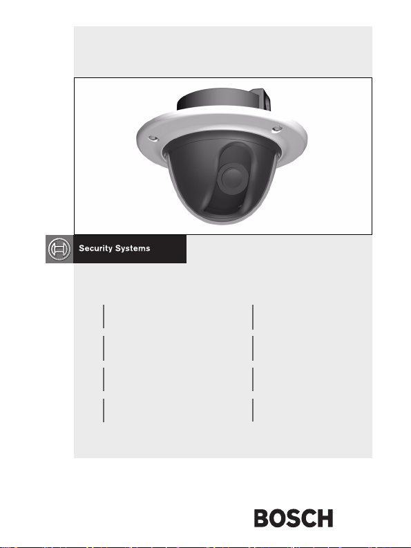
Introduction
The FlexiDomeXF camera is a small, discreet, high-security surveillance
dome containing a high-performance 1/3-inch CCD color camera with
integral varifocal lens. The integrated unit is mounted to an electrical box
or to a wall or ceiling. The sturdy construction and high impact resistant
polycarbon dome protect the camera module from damage.
The camera incorporates 15-bit digital signal processing for outstanding
picture performance under all lighting conditions. The FlexiDome
camera is easy to install and ready to use, and offers the best solution for
demanding scene conditions.
Features include:
• Impact-resistant dome
• Tamper-resistant housing
• Noise elimination, true color reproduction
• Adaptive dynamic range optimization
• Bilinx™ bi-directional coaxial communications
• Enhanced video motion detection
FlexiDome
DN
is the Day/Night camera version with mechanically
switching IR filter.
XF
Bosch Security Systems | 2005-10 | V1.0
Page 7
FlexiDome
XF & DN
| Installation Manual
EN | 6
Type number overview
FlexiDomeXF
Type number VDC-
Lens Varifocal
Standard PAL NTSC
Supply voltage 24 Vac, 50Hz or 12 Vdc 24 Vac, 60Hz or 12 Vdc
CCD type 1/3 "
FlexiDome
Type number VDN
Lens Varifocal Wide
Standard PAL NTSC
Supply voltage 24 Vac, 50Hz or 12 Vdc 24 Vac, 60Hz or 12 Vdc
CCD format 1/3 "
485V03-10
3-9.5 mm
F1.0-360
DN
495V03-10
3-9.5 mm
F1.0-360
VDC-
885V04-10
Varifocal
3.7-12 mm
F1.6-360
VDC-
485V03-20
Var ifo cal
3-9.5 mm
F1.0-360
Varifoca l Wide
VDN
495V03-20
3-9.5 mm
F1.0-360
VDC-
485V04-20
Varifocal
3.7-12 mm
F1.6-360
Unpacking
Unpack carefully and handle the equipment with care. The packaging
contains:
• Integrated FlexiDome camera
• Mounting hardware kit
• Special screwdriver for tamper resistant screw
• Lens adjustment cap
• Installation manual
Note
If equipment appears to have been damaged during shipment, repack it in
the original packaging and notify the shipping agent or supplier.
Bosch Security Systems | 2005-10 | V1.0
Page 8
FlexiDome
XF & DN
| Installation Manual
Caution
Installation should only be performed by qualified service
personnel in accordance with the National Electrical Code or
applicable local codes.
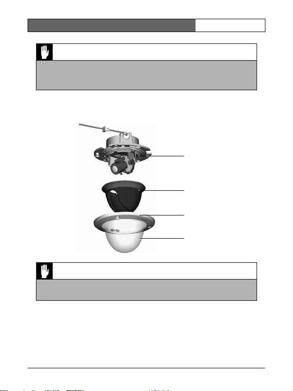
Disassembly
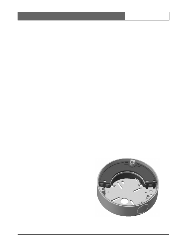
The camera/housing unit consists of the following parts:
Camera module and
mounting base
Inner liner
Trim rin g
Dome
Caution
The camera module is a sensitive device and must be handled
carefully. Do not drop when disassembling the unit.
EN | 7
To disasemble the unit proceed as follows:
• Using the special screwdriver, loosen the three tamper resistant screws
in the trim ring (the screws remain in place).
• Remove the trim ring with dome by pulling it off of the base.
• Remove the inner liner by pulling it off of the base.
Bosch Security Systems | 2005-10 | V1.0
Page 9
FlexiDome
XF & DN
| Installation Manual
EN | 8
Mounting the unit
The unit may be mounted in several different ways depending on the type
of surface, whether an electrical box is used and whether the connection is
via the rear or the side (surface mounted).
Caution
Installation should only be performed by qualified service
personnel in accordance with the National Electrical Code or
applicable local codes.
If the unit is surface mounted, use the separately available raised mounting
base (VDA 455SMB) and mount the unit onto this base.
Tips
• Refer to the dimensions drawing to find the exact position of the screw
holes and the entry hole for the wires.
• Partially screw in two screws for the keyholes and use them to
temporarily hang the camera while the connections are made.
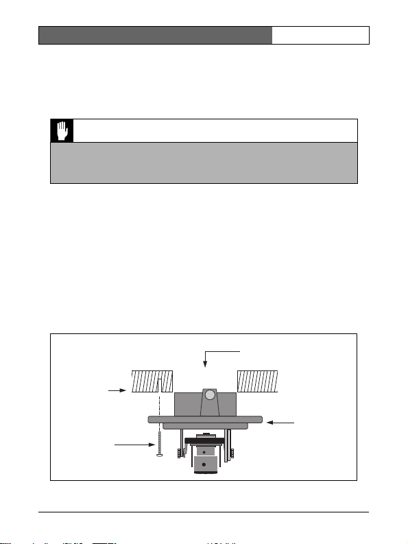
The following figures show the different ways of mounting the unit.
Figure 1 Rear connection - hollow surface
Wires
Strong surface
(four pre-drilled
8mm holes)
Three screws
(supplied)
Mounting
base
Bosch Security Systems | 2005-10 | V1.0
Page 10
FlexiDome
XF & DN
| Installation Manual
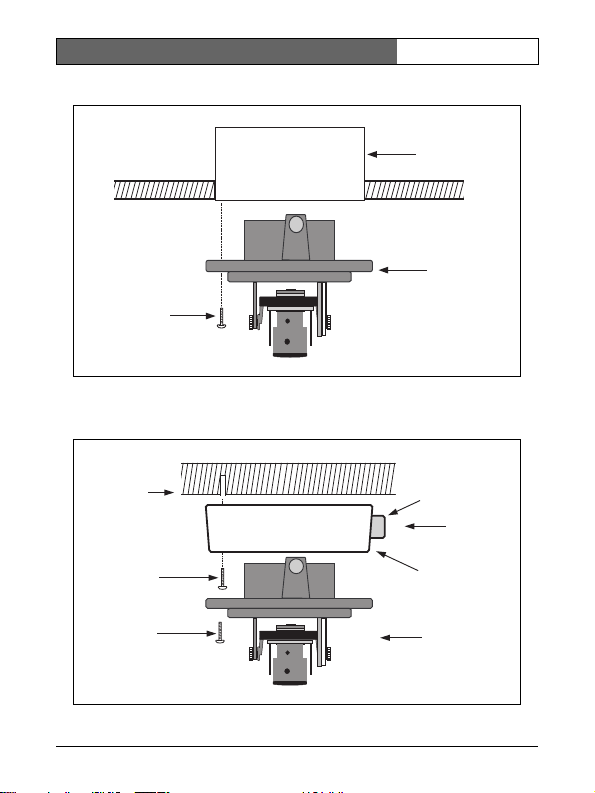
Figure 2 Connection to an electrical box (4S)
Two screws
(not supplied)
Figure 3 Surface mounting - side connection
EN | 9
S4 Electrical box
Mounting
base
Solid surface
(three pre-drilled
8mm holes)
Three screws
(supplied with
camera)
Three screws
(M5, supplied)
Bosch Security Systems | 2005-10 | V1.0
Conduit
Wires
Surface
mounting box
(VDA-455SMB)
Camera unit
and base
Page 11
FlexiDome
XF & DN
| Installation Manual
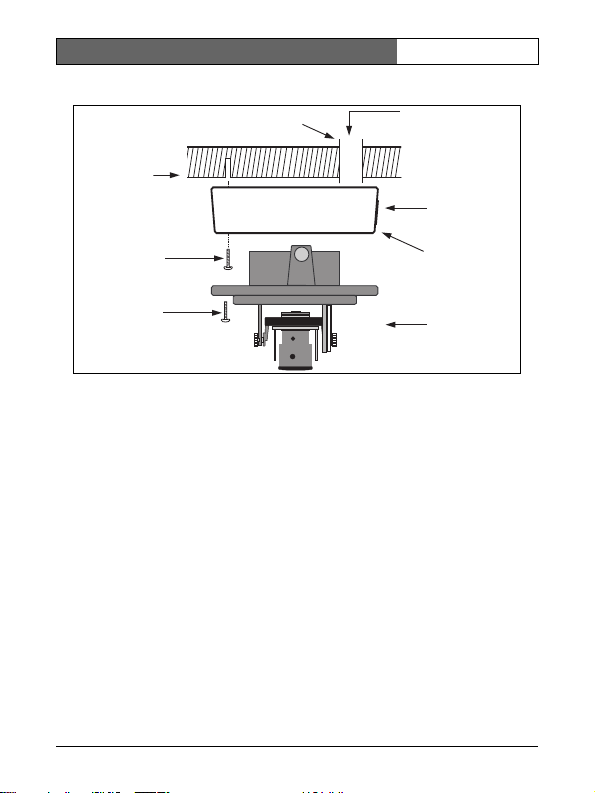
Figure 4 Surface mounting - rear connection
Conduit
Solid surface
(three pre-drilled
8mm holes)
EN | 10
Wires
Cap
Three screws
(supplied with
camera)
Three screws
(M5, supplied)
Surface
mounting box
(VDA-455SMB)
Camera unit
and base
Surface mounting
When using the surface mounting box:
• With a side connection, remove the cap covering the side entrance.
With a rear connection, leave the cap in place.
• Attach the conduit to the mounting base.
• Release the two clips at the bottom of the watertight connection
compartment to remove it from the mounting base.
• Open the cover of the watertight compartment in the mounting base by
releasing the 5 clips.
• Run the power and video wires through separate rubber grommets into
the watertight compartment.
• Run the cable from the camera into the watertight compartment
through the supplied grommet.
• Make the connection inside the watertight compartment and screw on
the cover to seal it.
Note
In order to ensure a watertight cable entry, use round cables of between 5
and 6 mm (0.2 - 0.24 inches) for power and video connection. Use some
silicon spray on the cable to help slide the grommets onto it.
Bosch Security Systems | 2005-10 | V1.0
Page 12
FlexiDome
XF & DN
| Installation Manual
EN | 11
Connection in outdoor applications
Safety precautions:
Coax grounding: If an outside cable system is connected to the unit,
ensure that the system is grounded.
U.S.A. models only - Section 810 of the National Electrical Code, ANSI/
NFPA No.70, provides information regarding proper grounding of the
mount and supporting structure, grounding of the coax to a discharge unit,
size of grounding conductors, location of discharge unit, connection to
ground electrodes, and requirements for the grounding electrode.
Power lines:
overhead power lines, electrical lights, or power circuits, or where it may
contact such power lines or circuits. When installing an outdoor system,
extreme care should be taken to keep from touching power lines or circuits,
as this contact may be fatal. U.S.A. models only - refer to the National
Electrical Code Article 820 regarding installation of CATV systems.
24 VAC power source:
source, this power source must comply with EN60950. When the unit is
intended to operate at 24 VAC, normal input voltage is between 12 VAC and
28 VAC. Voltage applied to the unit's power input should not exceed 28 VAC.
User supplied wiring, from 24 VAC supply to unit, must be in compliance
with electrical codes (Class 2 power levels). Do not ground the 24 VAC supply
at the terminals or at the unit's power supply terminals.
Connection: The unit has
connection terminals on flying
leads. In wet or outdoor
installations make use of the
VDA-455SMB accessory or use a
field wiring box with Nema3 or
IP55 protection level or better.
Make the connections inside the
water tight compartment. After
connections are made ensure that
the watertight compartment is
tightly closed and cables and
conduits are properly sealed to
prevent ingress of water.
An outdoor system should not be located in the vicinity of
This unit is intended to operate with a limited power
VDA-455SMB
Bosch Security Systems | 2005-10 | V1.0
Page 13
FlexiDome
XF & DN
| Installation Manual
EN | 12
Connection and set-up
Power and video connections
The wiring harness has a BNC connector to accept the video coax cable
(with male BNC connector) and two stripped low voltage power wires for
connection to a power connector. (A UTP adapter is available as an
accessory to allow a UTP video cable to be connected to the BNC
connector.)
Caution
Before proceeding, be sure to disconnect the power from the
cable to be installed into the unit. Be sure that the unit is of the
proper voltage type for the line power being used.
The easiest way to connect the low voltage power lines and the video
connection is as follows:
• Bring the building connections through the surface wire hole so that
they hang clear.
• Partially insert two screws into the pre-drilled holes (or adapter plate).
• Using the keyholes, hang the mounting base on one screw temporarily
and tilt the base slightly to gain access to the cable connections.
• Connect the BNC connector of the camera module to the video coax
cable.
• Connect the stripped power wires to the power supply connector.
Note
For a DC supply the polarity is not important. For an AC supply try to
maintain a consistent wiring polarity in multiple camera systems to help
avoid rolling when switching.
• In damp environments ensure that the connections are sealed. (The
surface mounting box has a sealed compartment for this.)
• Push the connections back through the surface wire hole.
• Secure the mounting base to the surface with three screws.
Bosch Security Systems | 2005-10 | V1.0
Page 14
FlexiDome
Setting up the camera
XF & DN
| Installation Manual
EN | 13
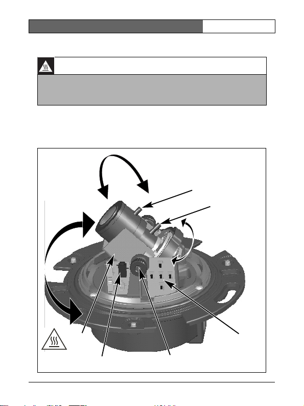
Warning: Hot Surface
The Heater will be HOT when in operation - DO NOT TOUCH.
Always switch the heater OFF, when working on the camera.
Refer to the installer menu (see Menu Structure) for instructions.
You can connect a monitor to the miniature 2.5mm jack socket on the
printed circuit board to help set up the camera. This socket provides a
composite video signal (with sync). An optional cable (code number
S1460) is available for making this connection.
Focus
Focal length
Heater
Monitor jack
Bosch Security Systems | 2005-10 | V1.0
Navigation
switches
Thumbwheels
Page 15
FlexiDome
XF & DN
| Installation Manual
EN | 14
Camera positioning
The physical default position of the camera is that the top of the image
corresponds to the indication TOP.
Caution
The CCD image sensors are highly sensitive and require special
care for proper performance and extended lifetime. Do not expose
them to direct sunlight or bright spotlights in operating and nonoperating conditions. Avoid bright lights in the field of view of the
camera.
The camera module position can be adjusted along three axes. When
adjusting the camera position ensure that the picture display on the
monitor is level. Set the camera to the desired position by performing the
following steps:
• For horizontal adjustment (pan), rotate the camera module in the base.
Do not rotate more than 360°.
• For vertical adjustment (tilt), loosen thumbscrews, position camera,
then gently tighten thumbscrews to secure camera.
• To obtain a horizontal horizon (for tilted ceilings or sidewall
mounting), rotate the base of the lens as necessary to align the picture
shown on the monitor. Do not rotate more than 340°.
Focal length and focus
Before adjusting, place the adjustment cap on the lens to ensure that the
image sharpnes is the same as when the dome is in place.
• To set the field of view of the varifocal lens, loosen the focal length
screw and turn the mechanism until the required view is displayed on
the monitor. (Image goes out of focus.)
• Focus the image on the monitor by loosening the focus screw and
turning the mechanism until the image is in focus.
• Readjust the focal length if necessary.
• Repeat these two adjustments until the desired view is in focus.
• Tighten both screws.
Remove the adjustment cap from the lens and the monitoring jack.
Bosch Security Systems | 2005-10 | V1.0
Page 16

FlexiDome
XF & DN
| Installation Manual
EN | 15
Heater
When using the camera at low temperatures, select the heater setting to
"Auto" in the Installer Menu (see Menu Structure).
Closing the unit
When the camera position is set and all adjustments have been made, close
the unit.
• Place the inner liner in position aligning its fin with the bracket on the
base.
• Place the dome onto the base and rotate until it clips into place. (If
necessary clean its surface with a soft cloth.)
• Place the sealing ring and the trim ring over the dome.
• Align the tamper resistant screws in the trim ring with a thread holes in
the mounting base.
• Use the special screwdriver supplied to tighten the three tamper
resistant screws.
Bosch Security Systems | 2005-10 | V1.0
Page 17

FlexiDome
XF & DN
| Installation Manual
EN | 16
Day/Night switching
The FlexiDomeDN Day/Night Camera is equipped with a motorized IR
filter. The IR filter can be removed in low-light or IR illuminated
applications.
If Auto switching mode is selected, the camera automatically switches the
filter depending on the observed light level. The switching level is
programmable. In Auto switching mode the camera prioritizes motion (the
camera gives sharp images without motion blur as long as the light level
permits) or color (the camera gives color pictures as long as the light level
permits). The camera recognizes IR illuminated scenes to prevent
unwanted switching to color mode.
There are two different methods of switching:
• via Bilinx™ communication, or
• automatically, based on the observed light levels.
Bosch Security Systems | 2005-10 | V1.0
Page 18

FlexiDome
XF & DN
| Installation Manual
EN | 17
Advanced Set-up
The FlexiDome
need for further adjustments. However, advanced set-up options are
available for getting the best results from the camera under special
circumstances. There are two upper level menus; a Main menu and an
Installer menu.
The Main menu allows you to select and set-up the picture enhancement
functions. If you are not happy with your changes, you can always recall
the default values for the mode.
The camera also has an Installer menu in which the installation settings
can be set.
The Main and Installer menus have functions that can be selected directly
or submenus for more detailed set-up.
XF&DN
normally provides an optimal picture without the
Accessing and navigating menus
Five keys are used for navigating through the various menus. To access the
set-up menus, press the menu/select key (center). The main menu appears
on the OSD. Use the arrow keys for navigation.
When the Bilinx™ communications link is active, the buttons on the
camera are disabled. You can also set up Bilinx™ so that the camera
buttons remain disabled even when Bilinx™ is not actively controlling the
camera. This prevents unauthorized change of the camera settings.
Bosch Security Systems | 2005-10 | V1.0
Page 19
FlexiDome
XF & DN
| Installation Manual
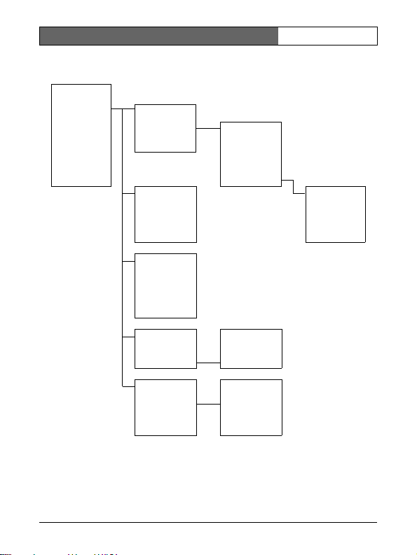
Menu Structure
Main menu
ALC
Enhance
Color
BLC
VMD
Exit
ALC
ENHANCE
COLOR
ALC level
Shut/Gain
Peak / average
ALC speed
Autoblack
Sharpness
DNR
XF-dynamic
White balance
WB speed
R-gain
G-gain
B-gain
Saturation
Shut/Gain
Shutter
Defshut
Sens up
Gain
Max. gain
Day/Night*
Day/Night
Day/night
Switch lvl
Priority
IR contrast
Mono burst
EN | 18
BLC
VMD
BLC
BLC level
BLC area
VMD
Area
Active
Motion
Sensitivity
Area
Area
* Only for the Day/Night version of the camera, other versions show NightSense.
Bosch Security Systems | 2005-10 | V1.0
Page 20
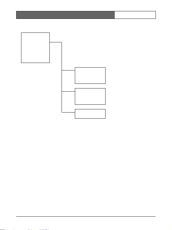
FlexiDome
Installer
Set focus now
Comm
Sync
Camera ID
Heater
Defaults
Exit
XF & DN
| Installation Manual
Sync
Sync
Detected sync
V phase
Camera ID
Camera ID
ID position
MAC address
Defaults
Restore all?
EN | 19
Bosch Security Systems | 2005-10 | V1.0
Page 21
FlexiDome
XF & DN
| Installation Manual
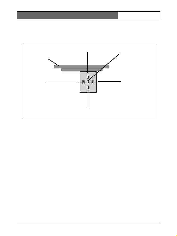
Hints for menu navigation
How to use the 5 keys
Camera
base
Up key
EN | 20
Menu/select key
Left key
Down key
• Press the menu/select key to access the menus or to move to the next
or previous menu.
• Press the menu/select key for approximately 1.5 seconds to open the
Installer menu.
• Use the up or down keys to scroll up or down through a menu.
• Use the left or right keys to move through options or to set parameters.
• When in a menu, quickly pressing the menu/select key twice restores
the selected item to its factory default.
• To close all menus at once from any menu, select the Exit item and
hold down the menu/select key until the menu display disappears.
Bosch Security Systems | 2005-10 | V1.0
Right key
Page 22
FlexiDome
XF & DN
| Installation Manual
EN | 21
Main menu
Function Selection Description
ALC Select submenu Select to access the video level control menu
ENHANCE Select submenu Select to access the picture enhancement menu
COLOR Select submenu Select to access the color control menu
BLC ON, OFF,
VMD OFF, SIL, OSD
EXIT Exit the menu
Select submenu
Select submenu
ALC submenu
Function Selection Description
ALC LEVEL -15 - 0 - +15 Adjusts the video output level
SHUTGAIN Select submenu Select to access the Shutter and Gain control
PEAK
AVERAGE
ALC SPEED Slow, Medium, Fast Adjust the speed of the video level control loop.
EXIT Return to Main menu
ALC --> Shutter/Gain submenu
Function Selection Description
SHUTTER AES, FL, FIXED • AES - auto-shutter - the camera automatically
-15 - 0 - +15 Adjust the balance between peak and average
•To enable Back Light Compensation (BLC)
operation set to ON
•Select to access the BLC menu
•To enable Video Motion Detection (VMD)
operation set to SIL (silent) or OSD (monitor
alarm generates on-screen message)
•Select to access the VMD menu
menu
video control
sets the optimum shutter speed
•FL - flickerless mode avoids interference from
light sources (recommended for use with video
iris or DC iris lenses only)
•FIXED - allows a user defined shutter speed
Bosch Security Systems | 2005-10 | V1.0
Page 23
FlexiDome
XF & DN
| Installation Manual
EN | 22
DEFSHUT 1/60 (1/50 ), 1/10 0,
FI X S HUT 1/60 (1/ 50), 1/100,
SENSUP OFF, 2x, 3x, …,10x Selects the factor by which the sensitivity of the
GAIN AGC, FIXED •In AGC mode the camera automatically sets the
MAXGAIN 0, 1, ... 26 Available in AGC mode only. Selects the
FIXGAIN 0, 1, ... 26 Available in FIXED gain operation only. Selects
NIGHTSENSE*
DAY/
NIGHT**
EXIT Return to the ALC menu
1/120 , 1/2 50,
1/5 00, 1/1000,
1/2000, 1/5000,
1/10K
1/120 , 1/2 50,
1/5 00, 1/1000,
1/2000, 1/5000,
1/10K
OFF, FORCED,
AUTO
Select submenu Select to access the day/night control menu
Only available if SHUTTER is AES. The camera
tries to maintain the selected shutter speed as
long as the light level of the scene permits.
Only available if SHUTTER is FIXED. Selects
shutter speed.
camera is increased.
gain to the lowest possible value needed to
maintain a good picture
•In FIXED mode the gain is set at a predefined
not scene dependent value
maximum value the gain can have during AGC
operation.
the gain setting.
Nightsense™ extends the low-light performance
of the camera.
•In AUTO mode, the camera automatically inches
to monochrome in low-light conditions.
•In FORCED mode, the camera remains in highsensitivity monochrome operation.
* Not in Day/Night version of camera.
** Only in Day/Night version of camera.
Note
If SENS UP is active, some noise or spots may appear in the picture. This
is normal camera behavior. SENS UP may cause some motion blur on
moving objects.
Bosch Security Systems | 2005-10 | V1.0
Page 24
FlexiDome
XF & DN
| Installation Manual
EN | 23
If the camera is in monochrome mode, all color related menu items are
disabled and cannot be accessed.
Day/Night submenu**
Function Selection Description
DAY/NIGHT COLOR, MONO,
SWITCH
LEVEL
PRIORITY COLOR, MOTION In AUTO mode:
IR
CONTRAST
MONO
BURST
EXIT Return to Shutter/Gain submenu
AUTO
-15 - 0 - +15 To set the video level in AUTO mode at which the
NORMAL,
ENHANCED
ON, OFF •OFF: the color burst in the video signal is
•In MONO mode the IR filter is removed, giving
full IR sensitivity.
•In AUTO mode the camera switches the filter
depending on the scene illumination level.
camera switches to monochrome operation.
• COLOR: the camera gives a color image as long
as the light level permits.
• MOTION: the camera avoids motion blur as long
as the light level permits.
•In Enhanced mode the camera optimizes
contrast in applications with high IR illumination
levels.
• In Normal mode the camera optimizes contrast in
mono applications with visible light illumination.
switched Off in monochrome mode of the
camera.
•ON: the color burst remains active even in
monochrome mode of the camera.
Enhance submenu
Function Selection Description
AUTO
BLACK
SHARPNESS
DNR
(dynamic
noise
reduction)
ON, OFF Autoblack ON automatically increases the
-15 - 0 - +15 Adjusts the sharpness of the picture. 0
AUTO, OFF In AUTO mode the camera automatically reduces
visibility of details
corresponds to the default position.
the noise in the picture. This may cause some
motion blur on moving objects.
Bosch Security Systems | 2005-10 | V1.0
Page 25
FlexiDome
XF & DN
| Installation Manual
EN | 24
XF-DYN
(dynamic
range
enhancement)
EXIT Return to Main menu
OFF, LOW, MID,
HIGH
In XF-DYN mode the camera automatically
optimizes the contrast in the picture.
Color submenu
Function Selection Description
WHITE
BALANCE
WB SPEED Slow, Medium, Fast Adjust the speed of the white balance control
RED gain -5 - 0 - +5 •ATW mode and AWB hold mode: adjusts the
BLUE gain -5 - 0 - +5 • ATW mode and AWB hold mode: adjusts the B
RED
GREEN
BLUE
SAT -15, … 0, … +5 Adjusts the color saturation. -15 will lead to a
EXIT Return to Main menu
ATW, MAN UAL,
AWB HOLD
-30 - 0 - +30 Controls all the colors individually for manual
•ATW: Auto tracking white balance allows the
camera to constantly adjust for optimal color
reproduction.
•AWB HOLD: Puts the ATW on hold and saves
the color settings.
• In MANUAL mode the Red, Green and Blue gain
can be manually set to a desired position
loop.
Red gain to optimize the white point.
gain to optimize around the white point.
white balance only.
monochrome image
Back Light Compensation (BLC) submenu
Function Selection Description
BLC ON, OFF When ON, the video level is optimized for the
BLC LVL -15,..0,..+15 BLC LEVEL adjust the balance between the
selected area of the image. Parts outside this area
may be underexposed or overexposed (this is
normal).
selected BLC area and its surrounding.
Bosch Security Systems | 2005-10 | V1.0
Page 26
FlexiDome
XF & DN
| Installation Manual
EN | 25
AREA Select submenu Select to access the Back Light Compensation
EXIT Return to Main menu
area menu (see selecting an area).
Selecting an area
To set-up an area for BLC (or VMD), access the area menu by selecting the
AREA option from the BLC (or VMD) menu. Upon entering the AREA
menu, the current area is displayed with the upper left corner flashing. The
flashing corner of the image can be moved with the Up, Down, Left, Right
arrow keys. Pressing the Select key moves the flashing cursor to the
opposite corner, which can now be moved. Pressing Select again freezes
the area and exits the area menu.
Video Motion Detection (VMD) submenu
Function Selection Description
VMD OFF, SIL, OSD When VMD is enabled and the camera can
AREA 1, 2, 3, 4,
ACTIVE ON, OFF Every area can be enabled individually by
MOTION Press SELECT to
SENS Use the LEFT/RIGHT keys to set the SENSitivity
EXIT Return to Main menu
Select submenu
reset indicator
Note
If VMD areas overlap, motion is only detected in the area with the lowest
sequence number.
generate SIL (silent) or OSD (monitor alarm
generates on-screen message) motion alarms.
•It is possible to set 4 motion sensitive areas (per
MODE).
•Press SELECT to enter the area set-up menu.
selecting YES.
Indicates the peak of measured motion in the
selected area
for motion to the desired level. Motion above this
level triggers alarm.
Bosch Security Systems | 2005-10 | V1.0
Page 27
FlexiDome
XF & DN
| Installation Manual
EN | 26
Installer Settings
Install menu
Function Selection Description
SET
FOCUS
NOW
COMM ON, OFF Bilinx communication ON/OFF
SYNC Select submenu Select to access the synchronization functions
CAMERA ID Select submenu Select to access ID menu
HEATER AUTO, OFF Select AUTO to enable the thermostatically
DEFAULTS Select submenu Return all settings for all modes to factory defaults
EXIT Exit the menu
Adjustment procedure DC-iris Lens:
1. Unlock the focus locking screw.
2. SET BACK FOCUS NOW is highlighted in the menu.
3. Turn the focus adjustment as required.
4. Lock the focus locking screw.
5. Exit the menu selection.
Install sync submenu
Function Selection Description
SYNC INTERNAL, LINE
DETECTED
SYNC
VPHASE 0, 2, … 358 Adjusts the vertical phase offset (when in LINE
EXIT Return to the Install menu
LOC K
Forces the lens to fully open the iris. Adjust the
lens focus now.
controlled heater function
Select INTERNAL for free running camera
operation, select LINE LOCK to lock to the power
supply frequency.
Shows the actual sync mode used by the camera.
LOCK mode and a valid power supply frequency
is detected).
Note
VPHASE cannot be accessed if there is no valid locking signal.
Bosch Security Systems | 2005-10 | V1.0
Page 28
FlexiDome
XF & DN
| Installation Manual
EN | 27
Install ID submenu
Function Selection Description
CAMERA ID Enter a 16 character camera name string. Use
ID POS OFF, TOP, BOT Select TOP to display the camera ID in the upper
EXIT Return to the Install menu
LEFT/RI GHT to change position in the string, use
UP/DOWN to select the character. Use SELECT
to exit the string edit screen.
left corner; select BOT for the lower left corner.
The ID string is not displayed when the OSD
menus are open.
Defaults submenu
Function Selection Description
ALL
DEFAULTS
EXIT Return to Install menu
Select to restore the factory defaults. A
confirmation screen appears. Allow 5 seconds for
the camera to optimize the picture after a mode
reset.
Camera Control Communication
This camera is equipped with a coaxial communications transceiver. In
combination with VP-CFGSFT, the camera can be adjusted from the headend side of the coaxial cable. All menus can be accessed remotely giving
full control of the camera. With this communication it is also possible to
disable the local keys on the camera.
To avoid loss of communication on an installed camera, the
COMMUNICATION ON/OFF selection is NOT available while using
remote control. This function can only be accessed with the camera
buttons.
Bosch Security Systems | 2005-10 | V1.0
Page 29
FlexiDome
XF & DN
| Installation Manual
Technical specification
EN | 28
Type number VDC-
Standard PAL NTSC
Active pixels 752x582 768x492
Rated supply
voltage
Min illumination < 0.35 lux, < 0.035 lux @ slow shutter
485V0x-10
24 VAC or 12 VDC
12-28 VAC (50/60 Hz)
11-3 6 V DC
< 0.13 lux, < 0.013 lux @ slow shutter (NightSense or Night mode)
VDN495V03-10
VDC485V0x-20
VDN495V03-20
All versions
Imager Interline CCD
Resolution 540 TVL
SNR > 50 dB
Video output 1 Vpp, 75 Ohm
Synchronization Internal or Line Lock selectable
Shutter AES (1/60 (1/50) to 1/10000), Flickerless, Fixed selectable
Day/Night** Color, Mono, Auto
Sens Up Adjustable from OFF to 10x
Auto black On, Off selectable
AGC AGC on or off (0 dB); maximum level selectable up to 28dB
XF-DYN Automatic dynamic range enhancement level selectable
DNR Automatic noise filtering ON/OFF selectable
Contour Sharpness enhancement level selectable
BLC BLC On or Off selectable, with programmable area
White balance Automatic 2500 - 9000K (with AWB hold mode and manual mode)
Color saturation Adjustable from monochrome (0%) to 133% color
ALC lens DC iris
Power
consumption
< 5 W
Bosch Security Systems | 2005-10 | V1.0
Page 30

FlexiDome
XF & DN
| Installation Manual
All versions
Dimensions 58 x 66 x 122 mm (HxWxL) without lens
Weight 550g without lens
Operating
temperature
Controls OSD with softkey operation
-30° to 50° C (-50° with heater AUTO enabled)
EN | 29
Bosch Security Systems | 2005-10 | V1.0
Page 31

FlexiDome
XF & DN
| Installation Manual
Dimensions (mm/inches)
EN | 30
4.77
121
57.6
2.27
95
3.7
158
6.22
57.6
2.27
33.3
66.5
85
39.5
1.3 1
2.62
3.35
1.56
Bosch Security Systems | 2005-10 | V1.0
Page 32

FlexiDome
XF & DN
| Installation Manual
EN | 31
Dimensions with surface mount box (mm/inch)
30.8
53.3
2.1
1.21
158
6.22
53.3
2.1
121
4.77
35
1.3 8
5.14
130.5
Bosch Security Systems | 2005-10 | V1.0
Page 33

FlexiDome
XF & DN
| Installation Manual
EN | 32
Accessories
Power transformers
• TC1334 120VAC, 60Hz - 24VAC, 30VA
• TC120PS 120VAC, 60Hz - 15VDC, 9VA
• TC220PSX-24 220-240VAC, 50/60Hz - 24VAC, 30VA
• TC220PS 220-240VAC, 50/60Hz - 15VDC, 9VA
Interface box:
• VP-CFGSFT Bilinx™ communication interface box and software
Bosch Security Systems | 2005-10 | V1.0
Page 34

FlexiDome
XF & DN
| Installation Manual
EN | 33
Bosch Security Systems | 2005-10 | V1.0
Page 35

FlexiDome
XF & DN
| Manuel d’utilisation
FR | 34
CONSIGNES DE SÉCURITÉ
Danger
Un triangle équilatéral comportant un éclair à extrémité fléchée
signale que le produit renferme une « tension potentiellement
dangereuse » non isolée, de puissance suffisante pour provoquer
une électrocution.
Avertissement
Un triangle équilatéral comportant un point d'exclamation signale
la présence d'instructions d'utilisation et d'entretien (dépannage)
importantes dans la documentation qui accompagne l'appareil.
Attention
Pour éviter tout risque d'électrocution, n'essayez pas de retirer le
capot (ou le panneau arrière). Cet appareil ne contient aucun
composant susceptible d'être réparé par l'utilisateur. Confiez la
réparation de l'appareil à du personnel qualifié.
Consignes de sécurité importantes
1. Lisez attentivement les instructions ci-après.
2. Conservez ces instructions pour référence ultérieure.
3. Conformez-vous aux différents avertissements fournis.
4. Suivez l'ensemble de ces instructions.
5. Évitez d'utiliser l'appareil à proximité d’une source d’humidité.
6. Pour nettoyer l'appareil, utilisez uniquement un chiffon sec.
7. N'obstruez en aucun cas les orifices d’aération. Installez l'appareil
conformément aux instructions du fabricant.
8. Évitez d'installer l'appareil à proximité de sources de chaleur telles
qu'un radiateur, une bouche d’air chaud, un four ou tout autre
dispositif générant de la chaleur (amplificateurs, etc.).
Bosch Security Systems | 10-2005 | V 1.0
Page 36

FlexiDome
9. La fiche de terre ou polarisée assure votre sécurité ; vous ne devez pas
10. Placez le cordon d’alimentation de sorte qu'il ne soit ni piétiné ni
11. Utilisez uniquement les accessoires et les dispositifs de fixation
12. Débranchez l'appareil en cas d'orage ou si vous n'avez pas l'intention
13. Toute opération de dépannage doit être confiée à un réparateur
14. Un interrupteur secteur omnipolaire, avec séparation des contacts de
XF & DN
| Manuel d’utilisation
la retirer. La fiche polarisée est formée d'une petite et d'une grande
broche. La fiche de terre est formée de deux broches et d'une borne de
mise à la terre. La broche la plus large et la borne de mise à la terre
sont conçues pour assurer votre sécurité. Si la fiche fournie n’entre pas
dans la prise que vous souhaitez utiliser, demandez conseil à un
électricien.
comprimé, en particulier au niveau de la fiche de connexion, de la
prise de courant et du point de sortie de l'appareil.
recommandés par le fabriquant.
de l'utiliser pendant une période prolongée.
qualifié. Une réparation s'impose lorsque l'appareil a été endommagé :
détérioration du cordon d'alimentation ou de la fiche, infiltration de
liquide, introduction d'objets, fonctionnement anormal ou chute de
l'appareil.
3 mm minimum entre chaque pôle, doit être intégré à l'installation
électrique du bâtiment.
FR | 35
Attention
Le bloc d'alimentation basse tension doit être conforme à la norme
EN/UL 60950. L'alimentation doit être fournie par une unité
SELV-LPS ou SELV - classe 2 (Safety Extra Low Voltage - Limited
Power Source).
Bosch Security Systems | 10-2005 | V 1.0
Page 37

FlexiDome
XF & DN
| Manuel d’utilisation
FR | 36
Informations FCC
Suite à différents tests, cet appareil s'est révélé conforme aux exigences
imposées aux appareils numériques de classe B, en vertu de la section 15
du règlement de la Commission fédérale des communications des ÉtatsUnis (FCC). Ces exigences visent à fournir une protection raisonnable
contre les interférences nuisibles dans le cadre d'une installation
résidentielle. Cet appareil génère, utilise et émet de l'énergie de
radiofréquences et peut, en cas d'installation ou d'utilisation non conforme
aux instructions, engendrer des interférences nuisibles au niveau des
radiocommunications. Cependant, l'absence d'interférences dans une
installation particulière n'est toutefois pas garantie. Il est possible de
déterminer la production d'interférences en mettant l'appareil
successivement hors et sous tension, tout en contrôlant la réception radio
ou télévision. L'utilisateur peut parvenir à éliminer les interférences
éventuelles en prenant une ou plusieurs des mesures suivantes :
• réorienter ou repositionner l'antenne réceptrice ;
• augmenter la distance entre l'équipement et le récepteur ;
• brancher l'équipement sur la prise d'un circuit différent de celui
auquel le récepteur est connecté ;
• consulter le revendeur ou un technicien qualifié en radio/télévision
pour obtenir de l'aide.
Remarque
Toute modification apportée au produit, non expressément approuvée par
Bosch, est susceptible d'entraîner la révocation du droit d'utilisation de
l'appareil. Pour obtenir de plus amples informations ou pour vous
entretenir avec un représentant, contactez le bureau
Bosch Security Systems le plus proche, ou visitez notre site Web à l'adresse
www.boschsecuritysystems.com.
Bosch Security Systems | 10-2005 | V 1.0
Page 38

Flexidome
XF & DN
| Guide d’installation
FR | 37
Introduction
La caméra FlexiDomeXF consiste en un dôme de surveillance haute
sécurité à la fois compact et discret. Elle intègre un capteur CCD couleur
1/3" hautes performances et un objectif varifocale. L'unité intégrée
s'installe sur un coffret de branchement ou se fixe au mur ou encore au
plafond. De construction robuste, le dôme en polycarbonate avec une
résistance élevée aux chocs assure la protection du module caméra contre
des dégradations éventuelles.
La caméra repose sur une technologie de traitement du signal numérique
15 bits. Résultat : une qualité d'image exceptionnelle, quelles que soient les
conditions de luminosité. Prête à l'emploi, la caméra FlexiDome
très facilement. Elle constitue la solution de choix pour les conditions de
prise de vue les plus délicates.
Parmi ses nombreuses fonctionnalités, citons :
• Bulle résistant aux chocs
• Boîtier anti-vandalisme
• Élimination des parasites, reproduction des couleurs naturelles
• Optimisation adaptative de la plage dynamique
• Communication bidirectionnelle Bilinx™
• Détection de mouvements améliorée
La caméra FlexiDome
DN
est la version jour/nuit intégrant un filtre IR à
commutation mécanique.
XF
s'installe
Bosch Security Systems | 10-2005 | V 1.0
Page 39

Flexidome
XF & DN
| Guide d’installation
Versions disponibles
FlexiDomeXF
Référence VDC-
Objectif Varifocale
Standard PAL NTSC
Tension
d'alimentation
Capteur CCD 1/3 "
FlexiDome
Référence VDN
Objectif Varifocale grand angle
Standard PAL NTSC
Tension
d'alimentation
Format CCD 1/ 3"
485V03-10
3 - 9,5 mm
F1.0 - 360
24 Vca, 50 Hz ou 12 Vcc 24 Vca, 60 Hz ou 12 Vcc
DN
24 Vca, 50 Hz ou 12 Vcc 24 Vca, 60 Hz ou 12 Vcc
495V03-10
3 - 9,5 mm
F1.0 - 360
VDC-
885V04-10
Varifocale
3,7 - 12 mm
F1.6 - 360
VDC-
485V03-20
Varifocale
3 - 9,5 mm
F1.0 - 360
VDN
495V03-20
Varifocale grand angle
3 - 9,5 mm
F1.0 - 360
485V04-20
Varifocale
3,7 - 12 mm
F1.6 - 360
Déballage
Déballez soigneusement l'appareil et manipulez-le avec précaution.
L'emballage contient les éléments suivants :
• Une caméra FlexiDome intégrée
• Un kit de montage
• Un tournevis spécial pour vis inviolables
• Une lentille de réglage de l'objectif
• Un manuel d'installation
Remarque
Si l'appareil a été endommagé lors du transport, replacez-le dans
l'emballage d'origine et avertissez le transporteur ou le fournisseur.
FR | 38
VDC-
Bosch Security Systems | 10-2005 | V 1.0
Page 40

Flexidome
XF & DN
| Guide d’installation
Attention
L'installation doit exclusivement être réalisée par du personnel
qualifié, conformément au code national d'électricité américain
(NEC) ou au code d'électricité local en vigueur.
Démontage
L'unité caméra/boîtier se compose des éléments suivants :
Module caméra et
socle de montage
Coque interne
Garniture
Bulle de protection
Attention
Le module caméra est un composant sensible devant être
manipulé avec le plus grand soin. Évitez de le laisser tomber lors
du démontage de l'unité.
FR | 39
Pour démonter l'unité, procédez comme suit :
• Utilisez le tournevis spécial pour desserrer les trois vis inviolables de la
garniture sans les retirer.
• Retirez la garniture et la bulle de la base.
• Retirez la coque interne de la base.
Bosch Security Systems | 10-2005 | V 1.0
Page 41

Flexidome
XF & DN
| Guide d’installation
FR | 40
Montage de l'unité
L'unité se monte de différentes façons selon le type de surface, l'utilisation
éventuelle d'un coffret de branchement et le type de connexion, à savoir
arrière ou latérale (montage en saillie).
Attention
L'installation doit exclusivement être réalisée par du personnel
qualifié, conformément au code national d'électricité américain
(NEC) ou au code d'électricité local en vigueur.
Pour monter l'unité en surface, utilisez le socle de montage en saillie fourni
séparément (VDA 455SMB).
Conseils
• Reportez-vous au schéma dimensionnel pour connaître l'emplacement
exact des trous de vis et du point d'entrée des câbles.
• Serrez partiellement deux vis via les orifices en forme de trous de
serrure pour fixer provisoirement la caméra pendant la réalisation des
connexions.
Les figures ci-après illustrent les différentes options de montage de l'unité.
Figure 1 Connexion arrière - Surface creuse
Fils
Surface dure
(trois trous préforés
de 8 mm)
Tro i s vi s
(fournies)
Socle de
montage
Bosch Security Systems | 10-2005 | V 1.0
Page 42

Flexidome
XF & DN
| Guide d’installation
Figure 2 Connexion à un coffret de branchement (4S)
Deux vis
(non fournies)
Figure 3 Montage en saillie - Connexion latérale
FR | 41
Coffret de
branchement S4
Socle de
montage
Surface
solide (trois trous
préforés de 8 mm)
Tro i s vi s
(fournies avec
la caméra)
Tro i s vi s
(M5, fournies)
Bosch Security Systems | 10-2005 | V 1.0
Gaine
Fils
Boîtier de
montage en saillie
(VDA-455SMB)
Unité caméra et
socle
Page 43

Flexidome
XF & DN
| Guide d’installation
Figure 4 Montage en saillie - Connexion arrière
Gaine
Surface
solide (trois trous
préforés de 8 mm)
FR | 42
Fils
Capuchon
Tr oi s v is
(fournies avec
la caméra)
Tr oi s v is
(M5, fournies)
Boîtier de
montage en
saillie
(VDA-455SMB)
Unité caméra et
socle
Montage en saillie
En cas d'utilisation du boîtier de montage en saillie :
• Avec connexion latérale : retirez le capuchon de l'entrée latérale.
Avec connexion arrière : ne retirez pas le capuchon de l'entrée latérale.
• Fixez la gaine sur le socle de montage.
• Détachez les deux clips situés à la base du compartiment de
branchement étanche pour le retirer du socle de montage.
• Détachez les 5 clips pour ouvrir le couvercle du compartiment étanche
du socle de montage.
• Utilisez des passe-fils en caoutchouc distincts pour acheminer les fils
électriques et vidéo vers le compartiment étanche.
• Acheminez le câble de la caméra dans le compartiment étanche via le
passe-fils.
• Effectuez les branchements nécessaires à l'intérieur du compartiment
étanche, puis encliquetez le couvercle pour le fermer et remettez le
compartiment en place.
Remarque
Pour garantir une entrée de câbles parfaitement étanche, utilisez des câbles
ronds de 5 et 6 mm pour la connexion des fils électriques et vidéo.
Appliquez de la silicone sur le câble à l'aide d'un spray pour faciliter
l'installation des passe-fils.
Bosch Security Systems | 10-2005 | V 1.0
Page 44

Flexidome
XF & DN
| Guide d’installation
FR | 43
Raccordement dans les applications
extérieures
Consignes de sécurité :
Mise à la terre du câble coaxial :
externe à l'appareil, assurez-vous que ce système est mis à la terre.
Modèles américains uniquement : la section 810 du code national d'électricité
américain (NEC), ANSI/NFPA n° 70, fournit des informations sur la mise à la
terre de la monture et de la structure portante, la mise à la terre du câble
coaxial vers un dispositif de décharge, la taille des conducteurs de terre,
l'emplacement du dispositif de décharge, la connexion aux électrodes de terre
et les exigences relatives aux électrodes de terre.
Lignes électriques :
lignes électriques aériennes, de systèmes d'éclairage électrique, de circuits
électriques, ou à un endroit où ils risquent d'entrer en contact avec de tels
dispositifs. Lors de l'installation d'un système d'extérieur, évitez de toucher les
lignes et les circuits électriques : un tel contact peut être fatal. Modèles
américains uniquement : consulter l’article 820 du Code national de l’électricité
(NEC) relatif à l’installation des circuits de câblodistribution (CATV).
Source d'alimentation 24 Vca :
limitée, qui doit être conforme à la norme EN60950. Pour les modèles nécessitant
une alimentation 24 Vca, utilisez une tension d'entrée standard comprise entre
12 Vca et 28 Vca. La tension appliquée à l'entrée d'alimentation de l'appareil ne
peut dépasser 28 Vca. Le câblage fourni par l'utilisateur, de l'alimentation 24 Vca
vers l'appareil, doit être conforme aux codes d'électricité en vigueur (niveaux de
puissance de classe 2). L'alimentation 24 Vca des bornes de connexion et des
bornes d'alimentation de l'appareil ne doit pas être mise à la terre.
Raccordement :
bornes de connexion sur les câbles
volants. En environnement humide ou
à l'extérieur, utilisez l'accessoire
VDA-455SMB ou un câblage
d'excitation avec un niveau de
protection NEMA 3, IP 55 ou
supérieur. Effectuez les branchements à
l'intérieur du compartiment étanche.
Une fois les connexions réalisées,
assurez-vous que le compartiment
étanche est fermé correctement et que
l'étanchéité des câbles et conduits est
optimale afin d'empêcher toute
infiltration de liquide.
évitez de placer les systèmes extérieurs à proximité de
l'appareil est doté de
si vous connectez un système de câblage
cet appareil nécessite une source d'alimentation
VDA-455SMB
Bosch Security Systems | 10-2005 | V 1.0
Page 45

Flexidome
XF & DN
| Guide d’installation
FR | 44
Connexion et installation
Connexion des fils électriques et vidéo
Le faisceau de câbles comporte un connecteur BNC acceptant le câble
coaxial vidéo (avec connecteur BNC mâle), ainsi que deux fils électriques
dénudés basse tension pour le branchement sur un boîtier d'alimentation.
(Un adaptateur UTP est disponible en option pour permettre la connexion
d'un câble vidéo UTP au connecteur BNC.)
Attention
Avant de poursuivre, coupez l'alimentation du câble à installer sur
l'unité. Vérifiez si la tension de l'unité correspond à celle de la ligne
utilisée.
Pour connecter les lignes électriques basse tension et établir la connexion
vidéo en toute simplicité, procédez comme suit :
• Acheminez les connexions de l'immeuble par le trou de la surface, de
sorte qu'elles sortent suffisamment.
• Insérez partiellement deux vis dans les trous préforés.
• Utilisez les orifices en forme de trous de serrure pour fixer
provisoirement le socle sur une vis, puis inclinez légèrement le socle
pour accéder aux raccords de câbles.
• Branchez le connecteur BNC du module caméra sur le câble coaxial
vidéo.
• Branchez les fils électriques dénudés sur le connecteur d'alimentation.
Remarque
Si vous utilisez une alimentation en courant continu, la polarité ne revêt
aucune importance particulière. En revanche, si vous utilisez une
alimentation en courant alternatif, essayez d'appliquer une polarité de
câblage cohérente dans les différents systèmes de caméras pour éviter les
problèmes de synchronisation lors de la commutation.
• Dans les environnements humides, vérifiez l'étanchéité des
connexions. (Le boîtier de montage en surface comprend un
compartiment étanche prévu à cet effet.)
• Repoussez les connexions par le trou de la surface.
• Fixez fermement le socle sur la surface à l'aide de trois vis.
Bosch Security Systems | 10-2005 | V 1.0
Page 46

Flexidome
Installation de la caméra
XF & DN
| Guide d’installation
FR | 45
Avertissement : Surface chaude
En cours de fonctionnement, le système de chauffage présente une
température élevée. NE le touchez en AUCUN cas. Éteignez toujours le
système de chauffage lorsque vous travaillez sur la caméra. Reportezvous aux instructions du menu Installer (voir la structure des menus).
Il est possible de connecter un moniteur au minijack 2,5 mm de la carte à
circuits imprimés pour faciliter l'installation de la caméra. Cette prise
fournit un signal vidéo composite (avec synchronisation). Vous pouvez
vous procurer un câble disponible en option (référence S1460) pour
réaliser cette connexion.
Mise au point
Distance focale
Système
de chauffage
Bosch Security Systems | 10-2005 | V 1.0
Commandes
de navigation
MolettesPrise pour moniteur
Page 47

Flexidome
XF & DN
| Guide d’installation
FR | 46
Mise en place de la caméra
Par défaut, la position physique de la caméra présente le haut de l'image
sur l'indication TOP.
Attention
Les capteurs d'image CCD sont des composants très sensibles.
Pour garantir une durée de vie et des performances optimales,
manipulez ces composants avec le plus grand soin. Évitez de les
exposer à la lumière directe du soleil et des spots lumineux, même
en cas de non-utilisation. Évitez la projection de lumière de forte
intensité dans le champ de vision de la caméra.
La position du module caméra se règle sur trois axes. Lors du réglage de la
position de la caméra, assurez-vous que l'image affichée sur le moniteur est
de niveau. Pour régler la caméra sur la position de votre choix, procédez
comme suit :
• Pour effectuer le réglage horizontal (balayage horizontal), faites pivoter
le module caméra dans le socle. Le module caméra ne doit pas pivoter
de plus de 360°.
• Pour effectuer le réglage vertical (balayage vertical), desserrez les vis à
oreilles, placez la caméra dans la position souhaitée, puis serrez les vis
sans forcer pour fixer la caméra.
• Pour obtenir un horizon horizontal (montage sur plafond incliné ou
piédroit), faites pivoter le socle de l'objectif de sorte à aligner l'image
affichée sur le moniteur. Le module caméra ne doit pas pivoter de plus
de 340°.
Distance focale et mise au point
Commencez par placer la lentille de réglage sur l'objectif de sorte que
l'image présente une netteté identique à celle observée lorsque la bulle est
mise en place.
• Pour procéder au réglage du champ de vision de l'objectif varifocale,
desserrez la vis de commande de la distance focale, puis tournez le
dispositif jusqu'à obtention du champ de vision souhaité sur le
moniteur (l'image est alors défocalisée).
Bosch Security Systems | 10-2005 | V 1.0
Page 48

Flexidome
XF & DN
| Guide d’installation
FR | 47
• Pour focaliser l'image sur le moniteur, desserrez la vis de commande de
la mise au point, puis tournez le dispositif jusqu'à obtention d'une
image focalisée.
• Au besoin, réglez de nouveau la distance focale.
• Recommencez ces deux réglages jusqu'à ce que le champ de vision
souhaité soit parfaitement focalisé.
• Serrez les deux vis.
Retirez la lentille de réglage de l'objectif et de la prise pour moniteur.
Système de chauffage
Lorsque vous utilisez la caméra à des températures peu élevées,
sélectionnez « Auto » dans le menu Installer (voir la structure des menus).
Fermeture de l'unité
Une fois la caméra installée et configurée selon vos besoins, fermez l'unité.
• Placez la coque interne en alignant son arête sur le support du socle.
• Placez la bulle sur le socle et faites-la pivoter jusqu'à ce qu'elle
s'encliquette. (Si nécessaire, nettoyez la surface à l'aide d'un chiffon
doux.)
• Placez la bague d'étanchéité et la garniture sur la bulle.
• Alignez les vis inviolables de la garniture sur les trous taraudés du socle
de montage.
• Utilisez le tournevis spécial fourni pour serrer les trois vis inviolables.
Bosch Security Systems | 10-2005 | V 1.0
Page 49

Flexidome
XF & DN
| Guide d’installation
FR | 48
Commutation jour/nuit
La caméra FlexiDomeDN jour/nuit est pourvue d'un filtre IR motorisé.
Ce filtre peut être retiré dans le cadre d'applications associées à une faible
luminosité ou à un éclairage infrarouge.
Lorsque le mode commutation automatique est sélectionné, la caméra
active automatiquement le filtre en fonction du niveau de luminosité.
Le niveau de luminosité associé à la commutation est programmable.
En mode commutation automatique, la caméra donne priorité aux
mouvements (restitution d'images nettes dépourvues de l'effet de flou avec
les objets en mouvement tant que le niveau de luminosité le permet) ou
aux couleurs (restitution d'images couleur tant que le niveau de luminosité
le permet). La caméra reconnaît les scènes éclairées par infrarouge et
empêche ainsi tout passage non souhaité en mode couleur.
La commutation peut s'effectuer de deux façons :
• via la technologie Bilinx™ ; ou
• de manière automatique, en fonction du niveau de luminosité.
Bosch Security Systems | 10-2005 | V 1.0
Page 50

Flexidome
XF & DN
| Guide d’installation
FR | 49
Configuration avancée
La caméra FlexiDomeXF restitue une image optimale sans qu'aucun réglage
supplémentaire ne soit nécessaire. Toutefois, les différentes options de
configuration avancée permettent d'obtenir un résultat idéal dans des
circonstances particulières. Le système comprend deux menus : Main et
Installer.
Le menu Main permet de sélectionner et de configurer les fonctions
d'optimisation de l'image. Si les modifications apportées ne vous
conviennent pas, vous avez toujours la possibilité de rétablir les valeurs par
défaut pour le mode en question.
La caméra présente également un menu Installer permettant la
configuration des paramètres d'installation.
Les fonctions des menus Main et Inst aller se sélectionnent soit
directement, soit par sous-menus pour une configuration plus détaillée.
Accès aux menus
La navigation dans les différents menus s'effectue à l'aide de cinq touches.
Pour accéder aux menus de configuration, appuyez sur la touche menu/
sélection (touche centrale). Le menu principal s'affiche à l'écran. Pour vous
déplacer, utilisez les touches fléchées.
Lorsque la communication Bilinx™ est active, les touches de la caméra
sont désactivées. Il est possible de paramétrer Bilinx™ de sorte que les
touches de la caméra restent désactivées lorsque Bilinx™ ne procède pas au
contrôle actif de l'appareil. Ce réglage empêche toute modification non
autorisée des paramètres de la caméra.
Bosch Security Systems | 10-2005 | V 1.0
Page 51

Flexidome
XF & DN
| Guide d’installation
Structure des menus
Main
ALC
Enhance
Color
BLC
VMD
Exit
ALC
ALC level
Shut/Gain
Peak/average
ALC speed
ENHANCE
Autoblack
Netteté
DNR
XF-dynamic
COLOR
White balance
WB speed
R-gain
G-gain
B-gain
Saturation
Shut/Gain
Shutter
Defshut
Sens up
Gain
Max. gain
Day/Night*
Day/Night
Day/night
Switch lvl
Priority
IR contrast
Mono burst
FR | 50
BLC
VMD
BLC
BLC level
BLC area
VMD
Area
Active
Motion
Sensitivity
Area
Area
* Versions jour/nuit uniquement. Pour les autres versions, l'option est NightSense.
Bosch Security Systems | 10-2005 | V 1.0
Page 52

Flexidome
Installer
Set focus now
Comm
Sync
Camera ID
Heater
Defaults
Exit
XF & DN
| Guide d’installation
Sync
Sync
Detected sync
V phase
Camera ID
Camera ID
ID position
MAC address
Defaults
Restore all?
FR | 51
Bosch Security Systems | 10-2005 | V 1.0
Page 53

Flexidome
XF & DN
| Guide d’installation
Conseils pour la navigation dans les menus
Utilisation des 5 touches
Socle de
caméra
Touche haut
Touche
menu/sélection
FR | 52
Touche
gauche
Touche bas
• Pour accéder aux menus, ou pour passer au menu précédent ou
suivant, appuyez sur la touche menu/sélection.
• Pour ouvrir le menu Installer, maintenez enfoncée la touche
menu/sélection pendant environ 1 seconde et demie.
• Pour faire défiler le menu vers le haut ou vers le bas, appuyez
respectivement sur la touche haut ou bas.
• Pour vous déplacer entre les options ou pour configurer les paramètres,
appuyez sur la touche gauche ou droite.
• Pour rétablir la valeur par défaut d'un élément de menu, appuyez
brièvement deux fois de suite sur la touche menu/sélection.
• Pour fermer tous les menus en une seule fois à partir d'un menu
quelconque, sélectionnez Exit et maintenez enfoncée la touche
menu/sélection jusqu'à disparition de l'affichage du menu.
Bosch Security Systems | 10-2005 | V 1.0
Touche droite
Page 54

Flexidome
XF & DN
| Guide d’installation
FR | 53
Menu Main
Fonction Sélection Description
ALC sous-menu Accès au menu de réglage du niveau vidéo.
ENHANCE sous-menu Accès au menu d'optimisation de l'image.
COLOR sous-menu Accès au menu de réglage de la couleur.
BLC ON, OFF,
VMD OFF, SIL, OSD
EXIT Sortie du menu.
sous-menu
sous-menu
Sous-menu ALC
Fonction Sélection Description
ALC LEVEL -15 - 0 - +15 Réglage du niveau de sortie vidéo.
SHUTGAIN sous-menu Accès au menu de réglage Shutter/Gain.
PEAK
AVERAGE
ALC SPEED Slow, Medium, Fast Vitesse de la boucle de réglage du niveau vidéo.
EXIT Retour au menu Main.
ALC --> sous-menu Shutter/Gain
Fonction Sélection Description
SHUTTER AES, FL, FIXED • AES (obturation automatique) : permet à la
-15 - 0 - +15 Balance entre le réglage vidéo maximal et moyen.
•Pour activer la compensation de contre-jour
(BLC), sélectionnez ON.
•Accès au menu BLC.
• Pour activer la détection de mouvements (VMD),
sélectionnez SIL (alarmes silencieuses) ou OSD
(alarme générant l'affichage d'un message à
l'écran).
•Accès au menu VMD.
caméra de sélectionner automatiquement la
vitesse d'obturation optimale.
•FL (mode anti-scintillement) : évite les
interférences avec les sources lumineuses
(recommandé pour objectifs à diaphragme vidéo
ou DC iris uniquement).
•FIXED (vitesse fixe) : permet l'adoption d'une
vitesse d'obturation définie par l'utilisateur.
Bosch Security Systems | 10-2005 | V 1.0
Page 55

Flexidome
XF & DN
| Guide d’installation
FR | 54
DEFSHUT 1/60 (1/50 ), 1/10 0,
FI X S HUT 1/60 (1/ 50), 1/100,
SENSUP OFF, 2x, 3x, …, 10x Sélection du facteur de multiplication de la
GAIN AGC, FIXED •En mode AGC, la caméra règle
MAXGAIN 0, 1, ..., 26 Disponible en mode AGC uniquement. Sélection
FIXGAIN 0, 1, ..., 26 Disponible en mode FIXED uniquement.
NIGHTSENSE*
DAY/
NIGHT**
EXIT Retour au menu ALC.
1/120 , 1/ 25 0, 1/5 00 ,
1/1 000, 1/2 000,
1/5 0 00, 1/10 00 0
1/120 , 1/ 25 0, 1/5 00 ,
1/1 000, 1/2 000,
1/5 0 00, 1/10 00 0
OFF, FORCED,
AUTO
sous-menu Accès au menu de commande jour/nuit.
Uniquement disponible si SHUTTER est défini
sur AES. La caméra essaie de maintenir la vitesse
d'obturation sélectionnée aussi longtemps que le
permet le niveau de luminosité de la prise de vue.
Uniquement disponible si SHUTTER est défini
sur FIXED. Sélection de la vitesse d'obturation.
sensibilité de la caméra.
automatiquement le gain sur la plus petite valeur
permettant de conserver une qualité d'image
optimale.
•En mode FIXED, le gain est réglé sur une valeur
prédéfinie indépendante de la prise de vue.
de la valeur maximale que peut atteindre le gain
en mode AGC.
Sélection des paramètres du gain.
NightSense™ accroît les performances de la
caméra dans des conditions de faible luminosité.
•En mode AUTO, la caméra passe
automatiquement à l'affichage monochrome
dans des conditions de faible luminosité.
• En mode FORCED, la caméra reste en affichage
monochrome haute sensibilité.
* À l'exception des versions jour/nuit.
** Versions jour/nuit uniquement.
Remarque
Lorsque la fonction SENS UP est activée, des parasites ou des taches
risquent d'apparaître sur l'image. Ce phénomène est tout à fait normal. Par
ailleurs, la fonction SENS UP peut provoquer un effet de flou au niveau
des objets en mouvement.
Bosch Security Systems | 10-2005 | V 1.0
Page 56

Flexidome
XF & DN
| Guide d’installation
FR | 55
Lorsque la caméra se trouve en mode monochrome, tous les éléments de
menu relatifs à la couleur sont désactivés et inaccessibles.
Sous-menu Day/Night**
Fonction Sélection Description
DAY/NIGHT COLOR,
SWITCH
LEVEL
PRIORITY COLOR,
IR
CONTRAST
MONO
BURST
EXIT Retour au sous-menu Shutter/Gain.
MONO, AUTO
-15 - 0 - +15 En mode AUTO, pour définir le niveau vidéo à partir
MOTION
NORMAL,
ENHANCED
ON, OFF • OFF : la salve de couleur du signal vidéo est
• En mode MONO, le filtre IR est retiré pour offrir une
sensibilité IR totale.
• En mode AUTO, la caméra active le filtre en fonction
du niveau de luminosité.
duquel la caméra passe en mode monochrome.
En mode AUTO :
• COLOR : la caméra restitue des images couleur tant
que le niveau de luminosité le permet.
• MOTION : la caméra restitue des images dépourvues
de flou au niveau des objets en mouvement tant que
le niveau de luminosité le permet.
• En mode Enhanced, la caméra optimise le contraste
pour les applications dont le niveau de luminosité IR
est élevé.
• En mode Normal, la caméra optimise le contraste
pour les applications monochromes dont la
luminosité est visible.
désactivée en mode monochrome.
• ON : la salve de couleur reste active même en mode
monochrome.
Sous-menu Enhance
Fonction Sélection Description
AUTO
BLACK
NETTETÉ -15 - 0 - +15 Réglage de la netteté de l'image. La valeur zéro
DNR
(Dynamic
Noise
Reduction)
ON, OFF Définie sur ON, cette fonction accroît
AUTO, OFF En mode AUTO, la caméra réduit automatiquement le
automatiquement la visibilité des détails.
correspond au réglage par défaut.
taux de parasites de l'image. L'activation de cette
fonction peut provoquer un effet de flou au niveau des
objets en mouvement.
Bosch Security Systems | 10-2005 | V 1.0
Page 57

Flexidome
XF & DN
| Guide d’installation
FR | 56
XF-DYN
(optimisation
de la plage
dynamique)
EXIT Retour au menu Main.
OFF, LOW,
MID, HIGH
En mode XF-DYN, la caméra optimise
automatiquement le contraste de l'image.
Sous-menu Color
Fonction Sélection Description
WHITE
BALANCE
WB SPEED Slow, Medium,
RED gain -5 - 0 - +5 •Modes ATW et AWB HOLD : réglage du gain du
BLUE gain -5 - 0 - +5 • Modes ATW et AWB HOLD : réglage du gain du bleu
RED
GREEN
BLUE
SAT - 15- 0- +5 Réglage de la saturation des couleurs. La valeur -15
EXIT Retour au menu Main.
ATW,
MANUAL,
AWB HOLD
Fast
-30 - 0 - +30 Paramétrage individuel des différentes couleurs pour
•ATW : grâce au réglage automatique de la balance
des blancs, la caméra garantit en permanence une
reproduction optimale des couleurs.
•AWB HOLD : bloque la fonction ATW pour
enregistrer les paramètres relatifs à la couleur.
•MANUAL : réglage manuel du gain du rouge, du vert
et du bleu sur la valeur de votre choix.
Vitesse de la boucle de réglage de la balance des
blancs.
rouge en vue d'optimiser le point blanc.
en vue d'optimiser les alentours du point blanc.
réglage manuel de la balance des blancs uniquement.
correspond à une image monochrome.
Sous-menu BLC
Fonction Sélection Description
BLC ON, OFF Définie sur ON, cette fonction optimise le niveau vidéo
BLC LVL -15 - 0 - +15 Balance entre la zone de compensation de contre-jour
pour la zone d'image sélectionnée. Les parties situées
à l'extérieur de cette zone risquent d'être sousexposées ou surexposées (ce phénomène est tout à
fait normal).
sélectionnée et les zones avoisinantes.
Bosch Security Systems | 10-2005 | V 1.0
Page 58

Flexidome
XF & DN
| Guide d’installation
FR | 57
AREA sous-menu Accès au menu de la zone de compensation de contre-
EXIT Retour au menu Main.
jour (voir « Sélection d'une zone »).
Sélection d'une zone
Pour configurer une zone de compensation de contre-jour (BLC) ou une
zone de détection de mouvements (VMD), accédez au menu de la zone
concernée en sélectionnant l'option AREA du menu BLC ou VMD.
Lorsque vous entrez dans le menu AREA, la zone actuelle s'affiche avec le
coin supérieur gauche clignotant. Pour déplacer le coin clignotant, utilisez
les touches fléchées haut, bas, gauche et droite. Pour déplacer le curseur
clignotant vers le coin opposé, appuyez sur la touche menu/sélection : vous
pouvez à présent déplacer le curseur. Pour geler la zone et quitter le menu
correspondant, appuyez de nouveau sur la touche menu/sélection.
Sous-menu VMD
Fonction Sélection Description
VMD OFF, SIL, OSD Lorsque cette fonction est activée, la caméra peut
AREA 1, 2, 3, 4,
ACTIVE ON, OFF Pour activer une zone individuellement, sélectionnez
MOTION Pour réinitialiser
SENS Pour régler la sensibilité aux mouvements sur le niveau
EXIT Retour au menu Main.
sous-menu
l'indicateur,
sélectionnez
SELECT.
Remarque
Lorsque des zones de détection de mouvements se chevauchent, les
mouvements sont uniquement détectés dans la zone présentant le numéro
de séquences le moins élevé.
générer des alarmes silencieuses (SIL) ou afficher des
messages d'alarme à l'écran (OSD) en cas de
détection de mouvements.
•Possibilité de définir 4 zones sensibles aux
mouvements (par mode).
•Pour accéder au menu de configuration d'une zone,
sélectionnez SELECT.
YES.
Valeur maximale de mouvements mesurée dans la zone
sélectionnée.
de votre choix, utilisez les touches gauche/droite. Tout
mouvement au-delà de ce niveau provoque le
déclenchement d'une alarme.
Bosch Security Systems | 10-2005 | V 1.0
Page 59

Flexidome
XF & DN
| Guide d’installation
FR | 58
Paramètres du menu Installer
Menu Install
Fonction Sélection Description
SET
FOCUS
NOW
COMM ON, OFF Pour activer/désactiver la transmission Bilinx.
SYNC sous-menu Accès aux fonctions de synchronisation.
CAMERA ID sous-menu Accès au menu I D.
HEATER AUTO, OFF Sélectionnez AUTO pour activer le système de
DEFAULTS sous-menu Restauration des valeurs par défaut de tous les
EXIT Sortie du menu.
Réglage d'un objectif DC iris :
1. Déverrouillez la vis de blocage de la mise au point.
2. L'élément SET BACK FOCUS NOW s'affiche en surbrillance.
3. Tournez la bague de mise au point sur la position de votre choix.
4. Verrouillez la vis de blocage de la mise au point.
5. Quittez le menu.
Sous-menu Install Sync
Fonction Sélection Description
SYNC INTER NAL,
DETECTED
SYNC
VPHASE 0, 2, …, 358 Réglage du décalage de la phase verticale (en cas de
EXIT Retour au menu Install.
Remarque
Quand aucun signal de verrouillage n'est valide, la fonction VPHASE est
inaccessible.
LINE LOCK
Pour ouvrir le diaphragme de l'objectif au maximum.
Réglez la mise au point à ce stade.
chauffage à commande thermostatique.
paramètres des différents modes.
Pour un fonctionnement libre de la caméra,
sélectionnez INTERNAL. Pour verrouiller la fréquence
d'alimentation, sélectionnez LINE LOCK.
Cette fonction indique le mode de synchronisation
utilisé par la caméra.
détection d'une fréquence d'alimentation valide en
mode LINE LOCK).
Bosch Security Systems | 10-2005 | V 1.0
Page 60

Flexidome
XF & DN
| Guide d’installation
FR | 59
Sous-menu Install ID
Fonction Sélection Description
CAMERA ID Saisissez un nom de caméra à 16 caractères.
ID POS OFF, TOP, BOT Pour afficher l'ID de la caméra dans le coin
EXIT Retour au menu Install.
Pour vous déplacer dans la chaîne de caractères,
utilisez les touches gauche/droite. Pour
sélectionner un caractère, utilisez les touches
haut/bas. Pour quitter l'écran de modification du
nom de la caméra, sélectionnez SELECT.
supérieur gauche, sélectionnez TOP. Pour
l'afficher dans le coin inférieur gauche,
sélectionnez BOT. La chaîne de l'ID ne s'affiche
pas lorsque les menus sont affichés à l'écran.
Sous-menu Defaults
Fonction Sélection Description
ALL
DEFAULTS
EXIT Retour au menu Install.
Restauration des valeurs par défaut. Un écran de
confirmation s'affiche. Patientez 5 secondes, le
temps que la caméra optimise l'image après
réinitialisation du mode.
Configuration de la caméra à distance
Cette caméra est équipée d'un émetteur-récepteur pour transmission
coaxiale. Combinée à l'interface USB VP-CFGSFT, la caméra peut se
configurer via le câble coaxial. Tous les menus sont dès lors accessibles
à distance, pour un contrôle total de l'appareil. Ce système de
communication permet également de désactiver les touches locales
de la caméra.
Pour éviter toute perte de communication au niveau de la caméra installée,
la fonction COMMUNICATION ON/OFF est indisponible lorsque la
télécommande est utilisée. Cette fonction est alors uniquement accessible
via les touches de la caméra.
Bosch Security Systems | 10-2005 | V 1.0
Page 61

Flexidome
XF & DN
| Guide d’installation
Caractéristiques techniques
FR | 60
Référence VDC-
Standard PAL NTSC
Pixels actifs 752 x 582 768 x 492
Tension
d'alimentation
nominale
Éclairage
minimum
485V0x-10
24 Vca ou 12 Vcc
12-28 Vca (50/60 Hz)
11-36 Vcc
< 0,35 lux, < 0,035 lux avec shutter lent
< 0,13 lux, < 0,013 lux avec shutter lent (NightSense ou mode nuit)
VDN495V03-10
VDC485V0x-20
VDN495V03-20
Toutes versions confondues
Capteur CCD à transfert d'interligne
Définition 540 lignes
Rapport signal/
bruit
Sortie vidéo 1 Vcàc, 75 ohms
Synchronisation Interne ou synchronisation secteur
Sh utt er O btur ati on a uto mat iqu e [1/60 (1/50 ) à 1/10 0 00],
Jour/nuit** Color, Mono, Auto
Sens Up Désactivation ou multiplication (jusqu'à 10)
Auto Black Activation ou désactivation
Contrôle
automatique de
gain (AGC)
XF-DYN Possibilité de régler le niveau d'optimisation automatique de la
DNR Activation ou désactivation de l'élimination automatique des
Contour Possibilité de régler le niveau d'optimisation de la netteté
>50dB
mode anti-scintillement ou vitesse fixe
Activation ou désactivation (0 dB) ; niveau maximum limité à 28 dB
gamme dynamique
parasites
Bosch Security Systems | 10-2005 | V 1.0
Page 62

Flexidome
XF & DN
| Guide d’installation
Toutes versions confondues
Compensation
de contre-jour
(BLC)
Balance des
blancs
Saturation des
couleurs
Objectif à
contrôle
automatique de
l'éclairage (ALC)
Consommation <5W
Dimensions 58x66x122mm (HxlxL)
Poids 550 g
Température
de
fonctionnement
Commandes Menus OSD via les touches de la caméra
Activation ou désactivation, avec zone programmable
Automatique 2 500 - 9 000 K (mode AWB HOLD et mode manuel)
Monochrome (0 %) à couleur (133 %)
DC iris
-30 °C à 50 °C
(-50 °C avec système de chauffage défini sur AUTO)
FR | 61
Bosch Security Systems | 10-2005 | V 1.0
Page 63

Flexidome
XF & DN
| Guide d’installation
Dimensions (mm/pouces)
FR | 62
4.77
121
57.6
2.27
95
3.7
158
6.22
57.6
2.27
66.5
85
39.5
33.3
1.3 1
2.62
3.35
1.56
Bosch Security Systems | 10-2005 | V 1.0
Page 64

Flexidome
XF & DN
| Guide d’installation
FR | 63
Dimensions avec boîtier de montage en saillie
(mm/po)
30.8
53.3
2.1
1.21
158
6.22
53.3
2.1
121
4.77
35
1.3 8
5.14
130.5
Bosch Security Systems | 10-2005 | V 1.0
Page 65

Flexidome
XF & DN
| Guide d’installation
FR | 64
Accessoires
Blocs d'alimentation
• TC1334 120 Vca, 60 Hz - 24 Vca, 30 VA
• TC120PS 120 Vca, 60 Hz - 15 Vcc, 9 VA
• TC220PSX-24 220-240 Vca, 50/60 Hz - 24 Vca, 30 VA
• TC220PS 220-240Vca, 50/60Hz - 15Vcc, 9VA
Interface
• VP-CFGSFT Logiciel et interface USB de communication Bilinx™
Bosch Security Systems | 10-2005 | V 1.0
Page 66

Flexidome
XF & DN
| Guide d’installation
FR | 65
Bosch Security Systems | 10-2005 | V 1.0
Page 67

FlexiDome
XF & DN
| Benutzerhandbuch
DE | 66
SICHERHEITSHINWEISE
Gefahr
Das Blitzsymbol in einem gleichseitigen Dreieck soll den Benutzer
auf nicht isolierte „gefährliche Spannung“ im Gehäuse aufmerksam
machen, die eventuell stark genug ist, um gesundheitliche Schäden
zu verursachen.
Warnung
Das Ausrufezeichen in einem gleichseitigen Dreieck soll den
Benutzer auf wichtige Anweisungen für die Bedienung und
Instandhaltung (Wartung) in den begleitenden Unterlagen
aufmerksam machen.
Vorsicht
Zur Vermeidung von Stromschlägen die Abdeckung (oder
Rückseite) nicht entfernen. Geräteinnenteile können vom Benutzer
nicht gewartet werden. Wartungsarbeiten sind ausschließlich von
qualifiziertem Wartungspersonal durchzuführen.
Wichtige Sicherheitsmaßnahmen
1. Lesen Sie diese Anweisungen bitte sorgfältig durch.
2. Bewahren Sie die Anweisungen für die spätere Verwendung auf.
3. Beachten Sie alle Warnungen.
4. Befolgen Sie die Anweisungen.
5. Vermeiden Sie direkten Kontakt mit Wasser.
6. Reinigen Sie das Gerät nur mit einem trockenen Tuch.
7. Achten Sie darauf, dass die Ventilationsöffnungen nicht abgedeckt
werden. Bei der Installation sind die Anweisungen des Herstellers zu
beachten.
8. Stellen Sie das Gerät nicht in unmittelbarer Nähe von Wärmequellen
wie Heizkörpern, Wärmespeichern, Öfen oder anderen Anlagen
(einschließlich Verstärkern) auf, die Wärme erzeugen.
Bosch Security Systems | Okt. 2005 | V 1.0
Page 68

FlexiDome
9. Beeinträchtigen Sie die Schutzfunktion des polarisierten oder geerdeten
10. Achten Sie insbesondere im Bereich von Steckern, Steckdosen und am
11. Verwenden Sie ausschließlich vom Hersteller angegebene
12. Trennen Sie das Gerät vom Stromnetz, wenn ein Gewitter aufkommt
13. Wartungsarbeiten sind ausschließlich von qualifiziertem
14. Die Elektroinstallation des Gebäudes muss eine Schalttafel mit einem
XF & DN
| Benutzerhandbuch
Steckers nicht durch Manipulation am Stecker. Ein polarisierter Stecker
hat zwei Kontakte unterschiedlicher Breite. Ein geerdeter Stecker hat zwei
Kontakte und einen dritten Erdungsanschluss. Der längere Kontakt
beziehungsweise der Erdungsanschluss dienen Ihrer Sicherheit. Wenn der
mitgelieferte Stecker nicht zur Steckdose am Einsatzort passt, lassen Sie
sich von einem Elektriker beraten.
Geräteausgang darauf, dass nicht auf das Netzkabel getreten oder dass das
Kabel nicht eingeklemmt werden kann.
Verlängerungskabel und entsprechendes Zubehör.
oder Sie es für längere Zeit nicht benutzen möchten.
Wartungspersonal durchzuführen. Wartungsarbeiten sind notwendig,
wenn die Anlage beschädigt wurde, beispielsweise bei einer Beschädigung
des Netzkabels oder -steckers, wenn Flüssigkeiten oder Gegenstände in
das Gerät gelangt sind, das Gerät Regen oder Nässe ausgesetzt war oder
wenn es fallengelassen wurde.
Kontaktabstand von mindestens 3 mm zwischen den einzelnen Polen
umfassen.
DE | 67
Vorsicht
Das Niederspannungs-Netzteil muss EN/UL 60950 entsprechen.
Bei dem Netzteil muss es sich um eine Einheit gemäß SELV-LPS
oder SELV – Class 2 (Safety Extra Low Voltage - Limited Power
Source) handeln.
Bosch Security Systems | Okt. 2005 | V 1.0
Page 69

FlexiDome
XF & DN
| Benutzerhandbuch
DE | 68
FCC-Informationen
Dieses Gerät wurde getestet und entspricht den Beschränkungen für
ein digitales Gerät der Klasse B entsprechend Abschnitt 15 der
FCC-Bestimmungen. Diese Beschränkungen sollen angemessenen Schutz
gegen schädliche Störungen beim Betrieb in einem Wohngebiet
gewährleisten. Dieses Gerät erzeugt und verwendet Funkwellen und kann
diese ausstrahlen. Bei unsachgemäßer Installation und Verwendung kann
es andere Funkkommunikation stören. Mögliche Störungen in speziellen
Installationen können jedoch nicht ausgeschlossen werden. Sollte das
Gerät die Funkkommunikation von Radios oder Fernsehgeräten stören,
was durch Aus- und Einschalten des Geräts überprüft werden kann, sollte
der Benutzer die Störungen anhand einer der folgenden Vorgehensweisen
beheben:
• Richten Sie die Empfangsantenne neu aus bzw. stellen Sie sie um.
• Erhöhen Sie den Abstand zwischen Gerät und Empfänger.
• Schließen Sie das Gerät an eine Steckdose an, die nicht vom
Empfänger verwendet wird.
• Bitten Sie ggf. den Händler oder einen erfahrenen Radio- und
Fernsehtechniker bzw. Informationselektroniker um Hilfe.
Hinweis
Durch Änderungen oder Modifikationen des Geräts, die nicht
ausdrücklich von Bosch genehmigt wurden, kann die Benutzerautorisierung für den Betrieb des Geräts erlöschen. Um weitere
Informationen zu erhalten bzw. persönlichen Kontakt zu einem Vertreter
aufzunehmen, wenden Sie sich bitte an die Bosch Security Systems
Niederlassung in Ihrer Nähe oder besuchen unsere Website unter
www.boschsecuritysystems.com.
Bosch Security Systems | Okt. 2005 | V 1.0
Page 70

FlexiDome
XF & DN
| Installationshandbuch
DE | 69
Einführung
Die FlexiDomeXF Kamera ist eine kleine, diskrete Überwachungskuppel für
höchste Sicherheit, die eine hoch leistungsfähige 1/3-Zoll-CCDFarbkamera mit integriertem Varifokalobjektiv umfasst. Die Kuppelkamera
kann an einem Schaltkasten, einer Wand oder der Decke montiert werden.
Die robuste Bauweise und hohe Stoßfestigkeit der Polykarbonat-Kuppel
schützen das Kameramodul vor Schäden.
Die integrierte digitale 15-Bit-Signalverarbeitung sorgt für herausragende
Bildqualität bei allen Lichtverhältnissen. Wegen ihrer unkomplizierten
Installation und Verwendung stellt die FlexiDome
problematische Aufnahmesituationen die optimale Lösung dar.
Sie bietet u. a. folgende Funktionen:
• Schlagfeste Kuppel
• Sabotagesicheres Gehäuse
• Rauschunterdrückung, Echtfarbwiedergabe
• Adaptive Optimierung des Dynamikbereichs
• Bilinx™ bidirektionale Koaxialkommunikation
• Optimierte Videobewegungserkennung
FlexiDome
DN
ist das Tag/Nacht-Kameramodell mit mechanisch
umschaltendem IR-Filter.
XF
Kamera auch für
Bosch Security Systems | Okt. 2005 | V 1.0
Page 71

FlexiDome
XF & DN
| Installationshandbuch
DE | 70
Überblick – Typennummer
FlexiDomeXF
Typennummer VDC-
Objektiv Varifokal
Standard PAL NTSC
Betriebsspannung 24 VAC, 50 Hz oder 12 VDC 24 VAC, 60 Hz oder 12 VDC
CCD-Typ 1/3 Zo ll
FlexiDome
Typennummer VDN
Objektiv Weitwinkel-Varifokal
Standard PAL NTSC
Betriebsspannung 24 VAC, 50 Hz oder 12 VDC 24 VAC, 60 Hz oder 12 VDC
CCD-Format 1/3 Zol l
485V03-10
3-9,5 mm
F1.0-360
DN
495V03-10
3-9,5 mm
F1.0-360
VDC-
885V04-10
Var ifok al
3,7-12 mm
F1.6-360
VDC-
485V03-20
Var ifok al
3-9,5 mm
F1.0-360
VDN
495V03-20
Weitwinkel-Varifokal
3-9,5 mm
F1.0-360
VDC-
485V04-20
Vari fok al
3,7-12 mm
F1.6-360
Auspacken
Packen Sie den Inhalt vorsichtig aus, und handhaben Sie das Gerät mit
äußerster Sorgfalt. Verpackungsinhalt:
• Integrierte FlexiDome Kamera
• Befestigungsteile
• Spezialschraubendreher für sabotagesichere Schrauben
• Objektivjustierkappe
• Installationshandbuch
Hinweis
Falls das Gerät während des Transports beschädigt wurde, verpacken Sie
es wieder in der Originalverpackung, und benachrichtigen Sie den
Lieferdienst bzw. Lieferanten.
Bosch Security Systems | Okt. 2005 | V 1.0
Page 72

FlexiDome
XF & DN
| Installationshandbuch
DE | 71
Vorsicht
Die Installation darf nur von qualifiziertem Kundendienstpersonal
gemäß jeweils zutreffenden Elektrovorschriften ausgeführt werden.
Demontage
Die Kamera/Gehäuse-Einheit besteht aus den folgenden Teilen:
Kameramodul und
Befestigungsrahmen
Inneneinsatz
Abdeckring
Kuppel
Vorsicht
Das Kameramodul ist ein empfindliches Gerät und muss mit
äußerster Sorgfalt gehandhabt werden. Lassen Sie das Gerät
bei der Demontage nicht fallen.
Gehen Sie bei der Demontage folgendermaßen vor:
• Lösen Sie mit Hilfe des Spezialschraubendrehers die drei
sabotagesicheren Schrauben am Abdeckring (ohne die Schrauben
vollständig herauszudrehen).
• Nehmen Sie den Abdeckring samt Kuppel ab, indem Sie ihn vom
Befestigungsrahmen abziehen.
• Ziehen Sie den Inneneinsatz vom Befestigungsrahmen ab.
Bosch Security Systems | Okt. 2005 | V 1.0
Page 73

FlexiDome
XF & DN
| Installationshandbuch
DE | 72
Montage
Das Gerät kann je nach Montagefläche auf unterschiedliche Art und Weise
befestigt werden – abhängig davon, ob ein Schaltkasten verwendet wird
oder der Anschluss über die Rückseite oder die Geräteseite erfolgt
(Aufputz-Montage).
Vorsicht
Die Installation darf nur von qualifiziertem Kundendienstpersonal
gemäß jeweils zutreffenden Elektrovorschriften ausgeführt werden.
Verwenden Sie bei Aufputz-Montage den separat erhältlichen erhöhten
Befestigungsrahmen (VDA 455SMB) zur Montage des Geräts.
Tipps
• Die exakte Position der Schraubenbohrungen und der Bohrung für die
Kabelzuführung können Sie der Maßzeichnung entnehmen.
• Drehen Sie zwei der Schrauben zur provisorischen Befestigung
teilweise ein, während Sie die elektrischen Anschlüsse vornehmen.
In den folgenden Abbildungen werden die unterschiedlichen
Befestigungsmöglichkeiten der Kamera dargestellt.
Abbildung 1 Rückseitiger Anschluss – hohle Montagefläche
Kabel
Massive
Montagefläche
(drei vorgebohrte
Löcher, 8 mm)
Drei Schrauben
(im Lieferumfang)
Befestigungsrahmen
Bosch Security Systems | Okt. 2005 | V 1.0
Page 74

FlexiDome
XF & DN
| Installationshandbuch
Abbildung 2 Anschluss an einen Schaltkasten (S4)
Zwei Schrauben
(nicht im Lieferumfang)
Abbildung 3 Aufputz-Montage – seitlicher Anschluss
DE | 73
S4 Schaltkasten
Befestigungsrahmen
Massive
Montagefläche
(drei vorgebohrte
Löcher, 8 mm)
Drei Schrauben
(im Lieferumfang
der Kamera)
Drei Schrauben
(M5, im Lieferumfang)
Bosch Security Systems | Okt. 2005 | V 1.0
Kabelkanal
Kabel
Befestigungsrahmen
für Aufputz-Montage
(VDA-455SMB)
Kameramodul
und Rahmen
Page 75

FlexiDome
XF & DN
| Installationshandbuch
Abbildung 4 Aufputz-Montage – rückseitiger Anschluss
Kabelkanal
Massive
Montagefläche
(drei vorgebohrte
Löcher, 8 mm)
DE | 74
Kabel
Kappe
Drei Schrauben
(im Lieferumfang
der Kamera)
Drei Schrauben
(M5, im Lieferumfang)
Befestigungsrahmen
für Aufputz-Montage
(VDA-455SMB)
Kameramodul
und Rahmen
Aufputz-Montage
Bei Verwendung des Befestigungsrahmens für die Aufputz-Montage gehen
Sie folgendermaßen vor:
• Bei seitlichem Anschluss nehmen Sie die Schutzkappe von der
seitlichen Öffnung ab.
Bei rückseitigem Anschluss belassen Sie die Schutzkappe auf der
seitlichen Öffnung.
• Befestigen Sie den Kabelkanal am Befestigungsrahmen.
• Lösen Sie die zwei Clips auf der Unterseite des wasserdichten
Anschlussfachs, und nehmen Sie es vom Befestigungsrahmen ab.
• Öffnen Sie die Abdeckung des wasserdichten Fachs im
Befestigungsrahmen, indem Sie die 5 Clips lösen.
• Führen Sie das Strom- und Videokabel durch separate
Gummidichtscheiben in das wasserdichte Anschlussfach.
• Führen Sie das Kamerakabel durch die mitgelieferte
Gummidichtscheibe in das wasserdichte Anschlussfach.
• Nehmen Sie die Anschlüsse im wasserdichten Anschlussfach vor.
Bringen Sie die Abdeckung mit den Clips wieder an, um die Dichtigkeit
des Fachs wiederherzustellen, und setzen Sie das Fach wieder ein.
Bosch Security Systems | Okt. 2005 | V 1.0
Page 76

FlexiDome
Hinweis
Um eine wasserdichte Kabelzuführung zu erzielen, verwenden Sie für den
Strom- und Videoanschluss runde Kabel mit einem Durchmesser von 5 bis
6 mm. Wenn Sie etwas Silikonspray auf die Kabel aufsprühen, lassen sich
die Gummidichtscheiben leichter über die Kabel führen.
XF & DN
| Installationshandbuch
DE | 75
Anschluss im Außenbereich
Sicherheitshinweise:
Koax-Erdung: Wenn ein Kabelsystem für den Außengebrauch mit dem
Gerät verbunden wird, muss das Kabelsystem geerdet sein. In den USA
erhältliche Modelle – Abschnitt 810 des National Electrical Code, ANSI/
NFPA No.70, enthält Informationen zur ordnungsgemäßen Erdung der
Halterung, zur Koax-Erdung an einem Entladegerät, zur Größe von
Erdungsleitern, zum Standort des Entladegeräts, zur Verbindung mit
Entladungselektroden und zu Anforderungen bezüglich der
Entladungselektroden.
Stromleitungen:
von Überlandleitungen, elektrischen Leitungen und Stromkreisen verwendet
werden, wo es mit diesen Leitungen oder Stromkreisen in Berührung
kommen kann. Bei der Installation eines Systems für den Außengebrauch
dürfen Sie keinesfalls mit solchen Stromleitungen oder -kreisen in Kontakt
kommen, da dieser Kontakt tödlich sein kann. In den USA erhältliche
Modelle – Befolgen Sie die Vorschriften des National Electrical Code Article
820 für die Installation von CATV-Systemen.
Stromquelle mit 24 VAC:
Stromquelle mit eingeschränkter Leistung ausgelegt. Diese Sromquelle muss
der Norm EN60950 entsprechen. Für Geräte, die bei 24 VAC betrieben
werden, beträgt die normale Eingangsspannung zwischen 12 VAC und
28 VAC. Die Eingangsspannung am Gerät darf 28 VAC nicht überschreiten.
Die vom Kunden bereitgestellte Verkabelung von der Stromquelle (24 VAC)
zum Gerät hat den elektrischen Codes (Klasse 2 Leistungsstufen) zu
entsprechen. Die Stromquelle (24 VAC) darf nicht an den Anschlüssen bzw.
an den Stromversorgungsanschlüssen am Gerät geerdet werden.
Ein System für den Außengebrauch darf nicht in der Nähe
Dieses Gerät ist für den Betrieb mit einer
Bosch Security Systems | Okt. 2005 | V 1.0
Page 77

FlexiDome
XF & DN
| Installationshandbuch
DE | 76
Anschluss:
Anschlusseingänge an freien
Kabelenden. Bei Montage an
feuchten Orten oder im
Außenbereich verwenden Sie das
VDA-455SMB Zubehör oder eine
Kabeldose für den Feldeinsatz mit
Schutzklasse Nema 3, IP 55 oder
höher. Nehmen Sie die Anschlüsse
im wasserdichten Anschlussfach
vor. Achten Sie nach dem
Anschließen darauf, dass das
wasserdichte Anschlussfach fest
verschlossen wird sowie die Kabel
und Kabelkanäle korrekt
abgedichtet sind, damit kein Wasser
Das Gerät verfügt über
eindringen kann.
VDA-455SMB
Bosch Security Systems | Okt. 2005 | V 1.0
Page 78

FlexiDome
XF & DN
| Installationshandbuch
DE | 77
Anschluss und Einrichtung
Strom- und Videoanschlüsse
Der Kabelbaum verfügt über einen BNC-Anschluss für ein Videokoaxialkabel
(mit BNC-Stecker) und zwei abisolierte Niedrigspannungsdrähte zum
Anschließen an einen Stromanschluss. (Ein UTP-Adapter ist als Zubehör
erhältlich, um den Anschluss eines UTP-Videokabels an den BNC-Stecker zu
ermöglichen.)
Vorsicht
Bevor Sie fortfahren, sollten Sie überprüfen, dass an dem Kabel,
das am Gerät angeschlossen werden soll, kein Strom anliegt.
Achten Sie darauf, dass das Gerät für die zu verwendende
Spannung geeignet ist.
So schließen Sie die Niederspannungsleitungen und Videoanschlüsse am
einfachsten an:
• Schieben Sie die Gebäudeanschlüsse durch die für die Kabel
vorgesehene Bohrung der Montagefläche, ohne sie zu fixieren.
• Drehen Sie zwei Schrauben teilweise in die vorgebohrten Löcher ein.
• Befestigen Sie den Befestigungsrahmen mit Hilfe der Hauptbohrungen
provisorisch mit einer Schraube, und kippen Sie den Rahmen leicht,
um freien Zugang zu den Kabelanschlüssen zu erhalten.
• Verbinden Sie den BNC-Stecker des Kameramoduls mit dem
Videokoaxialkabel.
• Schließen Sie die abisolierten Spannungsdrähte am Stromstecker an.
Hinweis
Bei Gleichstrom spielt die Polarität keine Rolle. Liegt Wechselstrom an,
sollten Sie auf eine konsistente Verkabelungspolarität in Systemen mit
mehreren Kameras achten, um Probleme beim Umschalten zwischen den
Kameras zu vermeiden.
• Stellen Sie in feuchten Umgebungen sicher, dass die Anschlüsse
ausreichend abgedichtet sind. (Der Befestigungsrahmen für die AufputzMontage verfügt zu diesem Zweck über ein wasserdichtes Anschlussfach.)
• Schieben Sie die Anschlüsse durch die für die Kabel vorgesehene
Bohrung der Montagefläche zurück.
• Befestigen Sie den Rahmen mit den drei Schrauben an der Montagefläche.
Bosch Security Systems | Okt. 2005 | V 1.0
Page 79

FlexiDome
XF & DN
| Installationshandbuch
Einrichtung der Kamera
Warnung: Heiße Fläche
Das Heizelement wird während des Betriebs HEISS – NICHT
BERÜHREN. Schalten Sie bei Arbeiten an der Kamera das
Heizelement immer AUS. Anweisungen finden Sie im Menü
Installer (siehe Menüstruktur).
Sie können einen Monitor an der 2,5 mm-Minibuchse der Platine
anschließen, um die Kamera einzurichten. Diese Buchse erzeugt ein
Composite Video-Signal (mit Sync). Die Verbindung kann über ein
optional erhältliches Kabel (Codenummer S1460) hergestellt werden.
Brennpunkt
Brennweite
DE | 78
Heizelement
Monitorbuchse
Bosch Security Systems | Okt. 2005 | V 1.0
Rändelschrauben
Navigationstasten
Page 80

FlexiDome
XF & DN
| Installationshandbuch
DE | 79
Kamerapositionierung
Bei der Standardposition der Kamera ist das obere Ende des Bildes an der
Anzeige TOP ausgerichtet.
Vorsicht
Die CCD-Bildsensoren sind besonders empfindlich und sollten
mit äußerster Sorgfalt gehandhabt werden, um eine hohe
Leistungsfähigkeit und längere Lebensdauer zu erzielen. Setzen
Sie sie sowohl bei Betrieb als auch bei Nichtverwendung nicht
direktem Sonnenlicht oder hellem Scheinwerferlicht aus.
Vermeiden Sie helles Licht im Blickfeld der Kamera.
Die Position des Kameramoduls kann entlang dreier Achsen eingestellt
werden. Achten Sie bei der Einstellung der Kameraposition darauf, dass
die Bildanzeige auf dem Monitor nicht schief ist. Stellen Sie die
gewünschte Kameraposition anhand der folgenden Schritte ein:
• Bei horizontaler Justierung (Schwenken) drehen Sie das Kameramodul
im Rahmen. Drehen Sie das Modul nicht weiter als 360°.
• Bei vertikaler Justierung (Neigen) lösen Sie die Rändelschrauben,
positionieren die Kamera, und ziehen Sie anschließend die
Rändelschrauben zum Befestigen der Kamera wieder an.
• Zur Erzielung eines waagerechten Horizonts (bei Deckenschräge oder
seitlicher Wandmontage) drehen Sie die Objektivunterlage
entsprechend, bis das auf dem Monitor angezeigte Bild exakt
ausgerichtet ist. Drehen Sie die Unterlage nicht weiter als 340°.
Bosch Security Systems | Okt. 2005 | V 1.0
Page 81

FlexiDome
XF & DN
| Installationshandbuch
DE | 80
Brennweite und Brennpunkt
Setzen Sie vor der Justierung die Justierkappe auf das Objektiv, damit die
Bildschärfe der Bildschärfe bei angebrachter Kuppel entspricht.
• Um das Sichtfeld des Varifokalobjektivs einzustellen, lösen Sie die
Schraube für die Brennweite und drehen den Mechanismus, bis das
gewünschte Sichtfeld auf dem Monitor angezeigt wird. (Bild wird
unscharf.)
• Fokussieren Sie das Bild auf dem Monitor, indem Sie die
Brennpunktschraube lösen und den Mechanismus drehen, bis der
Bildbrennpunkt exakt eingestellt ist.
• Justieren Sie ggf. die Brennweite erneut.
• Wiederholen Sie die beiden Justierschritte, bis die gewünschte Ansicht
eingestellt ist.
• Ziehen Sie die beiden Schrauben an.
Nehmen Sie die Justierkappe vom Objektiv und der Monitorbuchse ab.
Heizelement
Wenn Sie die Kamera bei niedrigen Temperaturen verwenden, stellen Sie
im Menü Installer die Option Heater auf "Auto" (siehe Menüstruktur).
Schließen des Geräts
Wenn die Kameraposition eingestellt und alle Justierungen vorgenommen
wurden, schließen Sie das Gerät.
• Setzen Sie den Inneneinsatz an die korrekte Position, indem Sie die
Wulst am Bügel des Rahmens ausrichten.
• Setzen Sie die Kuppel auf den Rahmen, und drehen Sie sie, bis sie
einrastet. (Reinigen Sie die Außenseite ggf. mit einem weichen Tuch.)
• Setzen Sie den Dichtring auf, und positionieren Sie anschließend den
Abdeckring über der Kuppel.
• Richten Sie die sabotagesicheren Schrauben im Abdeckring an den
Einschraubbohrungen im Befestigungsrahmen aus.
• Ziehen Sie die sabotagesicheren Schrauben mit Hilfe des im
Lieferumfang enthaltenen Spezialschraubendrehers fest.
Bosch Security Systems | Okt. 2005 | V 1.0
Page 82

FlexiDome
XF & DN
| Installationshandbuch
DE | 81
Umschaltung zwischen Tag/Nacht
Die FlexiDomeDN Tag/Nacht-Kamera verfügt über einen motorbetriebenen
IR-Filter. Der IR-Filter kann bei schlechten Lichtverhältnissen oder
IR-beleuchteten Anwendungen abgenommen werden.
Wenn der Modus für die automatische Umschaltung ausgewählt wurde,
schaltet die Kamera je nach Lichtstärke automatisch den Filter um. Sie
können programmieren, bei welcher Lichtstärke umgeschaltet werden soll.
Im Modus für die automatische Umschaltung legt die Kamera entweder
den Schwerpunkt auf Bewegung oder auf Farbe. Dies bedeutet, dass die
Kamera bei unzureichender Lichtstärke scharfe Bilder ohne
Bewegungsunschärfe und bei ausreichender Lichtstärke Farbbilder liefert.
Die Kamera erkennt IR-beleuchtete Szenen, um unerwünschtes
Umschalten in den Farbmodus zu vermeiden.
Es stehen zwei verschiedene Umschaltmethoden zur Verfügung:
• über Bilinx™-Kommunikation oder
• automatisch, je nach Lichtstärke.
Bosch Security Systems | Okt. 2005 | V 1.0
Page 83

FlexiDome
XF & DN
| Installationshandbuch
DE | 82
Erweiterte Einrichtung
Normalerweise bietet die FlexiDome
optimale Bildqualität. Unter außergewöhnlichen Einsatzbedingungen
bietet die erweiterte Einrichtung jedoch zusätzliche Optimierungsmöglichkeiten. Es gibt zwei Hauptmenüs: das Menü Main und das Menü
Installer.
Über das Menü Main können Sie die Bildoptimierungsfunktionen
auswählen und einrichten. Falls Sie mit Ihren Änderungen nicht zufrieden
sind, können Sie jederzeit die Standardeinstellungen für die jeweilige
Betriebsart wiederherstellen.
Über das Menü Installer können Sie die Installationseinstellungen
anpassen.
Die Menüs Main und Installer umfassen Funktionen, die Sie direkt
auswählen können, sowie Untermenüs mit weiteren Funktionen für eine
detailliertere Einrichtung.
XF&DN
ohne weitere Einrichtung eine
Aufrufen und Verwenden von Menüs
Fünf Tasten dienen zur Navigation durch die Menüstruktur. Um die
Einrichtungsmenüs aufzurufen, drücken Sie die Menü-/Auswahltaste
(Mitte). Auf dem Bildschirm wird das Hauptmenü angezeigt. Verwenden
Sie die Pfeiltasten, um die Markierung durch die Menüstruktur zu
bewegen.
Wenn die Bilinx™-Kommunikationsverbindung aktiv ist, sind die Tasten
deaktiviert. Sie können Bilinx™ auch so einrichten, dass die Tasten auch
dann deaktiviert sind, wenn keine aktive Bilinx™-Verbindung besteht.
Dadurch können Sie verhindern, dass Unbefugte die Kameraeinstellungen
ändern.
Bosch Security Systems | Okt. 2005 | V 1.0
Page 84

FlexiDome
XF & DN
| Installationshandbuch
Menüstruktur
Main
ALC
Enhance
Color
BLC
VMD
Exit
ALC
ALC level
Shut/Gain
Peak / average
ALC speed
ENHANCE
Autoblack
Sharpness
DNR
XF-dynamic
COLOR
White balance
WB speed
R-gain
G-gain
B-gain
Saturation
Shut/Gain
Shutter
Defshut
Sens up
Gain
Max. gain
Day/Night*
DE | 83
Day/Night
Day/night
Switch lvl
Priority
IR contrast
Mono burst
BLC
BLC
BLC level
BLC area
VMD
VMD
Area
Active
Motion
Sensitivity
* Nur bei dem Tag/Nacht-Modell der Kamera. Bei anderen Modellen lautet die Option
NightSense.
Area
Area
Bosch Security Systems | Okt. 2005 | V 1.0
Page 85

FlexiDome
Installer
Set focus now
Comm
Sync
Camera ID
Heater
Defaults
Exit
XF & DN
| Installationshandbuch
Sync
Sync
Detected sync
V phase
Camera ID
Camera ID
ID position
MAC address
Defaults
Restore all?
DE | 84
Bosch Security Systems | Okt. 2005 | V 1.0
Page 86

FlexiDome
XF & DN
| Installationshandbuch
Hinweise zur Menünavigation
So verwenden Sie die fünf Tasten
Auf-Taste
Kameraunterlage
DE | 85
Menü-/
Auswahltaste
Links-
Ta st e
Ab-Taste
• Drücken Sie die Menü-/Auswahltaste, um die Menüs aufzurufen und
zwischen den einzelnen Menüs zu wechseln.
• Drücken Sie die Menü-/Auswahltaste etwa 1,5 Sekunden lang, um das
Menü Inst aller aufzurufen.
• Verwenden Sie die Auf- und Ab-Pfeiltasten, um die Markierung in
einem Menü nach oben bzw. nach unten zu bewegen.
• Verwenden Sie die Links- und Rechts-Pfeiltasten, um einzelne
Optionen auszuwählen und Parameter einzustellen.
• Wenn Sie in einem Menü zweimal schnell hintereinander die
Menü-/Auswahltaste drücken, wird die ausgewählte Option auf
die Standardeinstellung zurückgesetzt.
• Um von einem beliebigen Menü aus sämtliche Menüs zu
schließen, wählen Sie die Option Exit aus, und halten Sie die
Menü-/Auswahltaste gedrückt, bis die Menüanzeige
ausgeblendet wird.
Bosch Security Systems | Okt. 2005 | V 1.0
Rechts-Taste
Page 87

FlexiDome
XF & DN
| Installationshandbuch
DE | 86
Menü Main
Funktion Auswahl Beschreibung
ALC Untermenü Aufrufen des Menüs zur Steuerung des Videopegels
ENHANCE Untermenü Aufrufen des Menüs zur Bildoptimierung
COLOR Untermenü Aufrufen des Menüs zur Farbsteuerung
BLC ON, OFF,
VMD OFF, SIL, OSD
EXIT Beenden des Menüs
Untermenü
Untermenü
Untermenü ALC
Funktion Auswahl Beschreibung
ALC LEVEL -15 - 0 - +15 Anpassen des Videoausgangspegels
SHUTGAIN Untermenü Aufrufen des Menüs zur Steuerung von Shutter und
PEAK
AVERAGE
ALC SPEED Slow, Medium,
EXIT Zurückkehren ins Menü Main
ALC --> Untermenü SHUT/GAIN
Funktion Auswahl Beschreibung
SHUTTER AES, FL, FIXED • AES - Auto-Shutter - Die Kamera legt automatisch
-15 - 0 - +15 Justieren der Balance der Videoregelung zwischen
Fast
•Aktivieren der Gegenlichtkompensation
(BLC = Back Light Compensation) mit ON
•Aufrufen des Menüs BLC
•Aktivieren der Videobewegungserkennung (VMD =
Video Motion Detection) mit SIL (still) oder OSD
(auf dem Bildschirm wird eine Meldung angezeigt)
•Aufrufen des Menüs VMD
Verstärkung
Spitzenwert und Durchschnitt
Anpassen der Geschwindigkeit (Langsam, Mittel,
Schnell) der Videopegelregelung
die optimale Shutter-Geschwindigkeit fest.
•FL - Flimmerfrei - Vermeidet Beeinträchtigung durch
externe Lichtquellen (nur zur Verwendung mit
Objektiven mit Video- oder DC-Blenden empfohlen).
•FIXED - Fest - Erlaubt die Verwendung einer
benutzerdefinierten (festen) ShutterGeschwindigkeit.
Bosch Security Systems | Okt. 2005 | V 1.0
Page 88

FlexiDome
XF & DN
| Installationshandbuch
DE | 87
DEFSHUT 1/60 (1/50 ),
FI X S HUT 1/60 (1/ 50),
SENSUP OFF, 2x,
GAIN AGC, FIXED • Im Modus AGC wird die Verstärkung der Kamera
MAXGAIN 0, 1, ... 26 Nur verfügbar im Modus AGC. Auswählen des
FIXGAIN 0, 1, ... 26 Nur verfügbar im Modus FIXED. Auswählen des
NIGHTSENSE*
DAY/
NIGHT**
EXIT Zurückkehren ins Menü ALC.
1/100 , 1/120,
1/250, 1/500,
1/100 0, 1/2000,
1/5 000, 1/10K
1/100 , 1/120,
1/250, 1/500,
1/100 0, 1/2000,
1/5 000, 1/10K
3x, …,10x
OFF, FORCED,
AUTO
Untermenü Aufrufen des Menüs zur Steuerung der Tag/Nacht-
Nur verfügbar, wenn SHUTTER auf AES gesetzt ist.
Die Kamera versucht die ausgewählte ShutterGeschwindigkeit so lange zu verwenden, wie es die
Lichtverhältnisse erlauben.
Nur verfügbar, wenn SHUTTER auf FIXED gesetzt
ist. Auswählen der Shutter-Geschwindigkeit.
Auswählen des Faktors, um den die Empfindlichkeit
der Kamera erhöht wird.
automatisch auf den niedrigsten Wert gesetzt, bei
dem eine gute Bildqualität noch möglich ist.
•Im Modus FIXED wird ein fester Verstärkungswert
voreingestellt.
höchsten Wertes, den die Verstärkung im Modus
AGC annehmen kann.
Verstärkungswertes.
Nightsense™ steigert die Kameraempfindlichkeit bei
schlechten Lichtverhältnissen.
•Im Modus AUTO nähert sich die Kamera bei
abnehmendem Licht automatisch
Monochrombetrieb an.
•Im Modus FORCE D bleibt die Kamera stets im
hochempfindlichen Monochrombereich.
Umschaltung.
* Nicht bei den Tag/Nacht-Kameramodellen.
** Nur bei den Tag/Nacht-Kameramodellen.
Hinweis
Ist SENS UP aktiv, kann das Bild durch Flecken oder Rauschen
beeinträchtigt werden. Dieses Kameraverhalten ist normal. SENS UP kann
bei beweglichen Objekten zu Bewegungsunschärfe führen.
Bosch Security Systems | Okt. 2005 | V 1.0
Page 89

FlexiDome
XF & DN
| Installationshandbuch
Wenn sich die Kamera im Schwarzweißmodus befindet, sind keine
farbbezogenen Menüoptionen verfügbar.
Untermenü Day/Night**
Funktion Auswahl Beschreibung
DAY/NIGHT COLOR, MONO,
SWITCH
LEVEL
PRIORITY COLOR, MOTION Im Modus AUTO:
IR
CONTRAST
MONO
BURST
EXIT Zurück zum Untermenü Shut/Gain.
AUTO
-15 - 0 - +15 Setzt den Videopegel in den Modus AUTO, in
NORMAL,
ENHANCED
ON, OFF •OFF: Der Farbburst im Videosignal ist im
•Im Modus MONO wird der IR-Filter
ausgeschaltet, um volle IR-Empfindlichkeit zu
gewährleisten.
•Im Modus AUTO wechselt die Kamera den Filter
je nach den Lichtverhältnissen der Szene.
dem die Kamera in den Monochrombetrieb
umschaltet.
•COLOR: Die Kamera nimmt ein Farbbild auf, so
lange die Lichtverhältnisse dies zulassen.
•MOTION: Die Kamera vermeidet
Bewegungsunschärfe, so lange die
Lichtverhältnisse dies zulassen.
•Im Modus Enhanced optimiert die Kamera den
Kontrast bei Anwendungen mit Licht aus dem
IR-Spektrum.
•Im Modus Normal optimiert die Kamera den
Kontrast bei Schwarzweißanwendungen mit
Licht aus dem sichtbaren Spektrum.
Schwarzweißmodus der Kamera ausgeschaltet.
•ON: Der Farbburst bleibt auch im
Schwarzweißmodus der Kamera aktiv.
Untermenü Enhance
Funktion Auswahl Beschreibung
AUTO
BLACK
SHARPNESS
ON, OFF Ist AUTO BLACK aktiviert (ON), wird die
-15 - 0 - +15 Anpassen der Bildschärfe. 0 entspricht der
Detaildarstellung automatisch verbessert.
Standardeinstellung.
DE | 88
Bosch Security Systems | Okt. 2005 | V 1.0
Page 90

FlexiDome
XF & DN
| Installationshandbuch
DE | 89
DNR
(Dynamic
Noise
Reduction)
XF-DYN
(Dynamic
Range
Enhancement)
EXIT Zurückkehren ins Menü Main.
AUTO, OFF Wenn AUTO aktiviert ist, reduziert die Kamera
OFF, LOW, MID,
HIGH
automatisch das Bildrauschen. Dies kann bei
beweglichen Objekten zu Bewegungsunschärfe
führen.
Im Modus XF-DYN optimiert die Kamera
automatisch den Bildkontrast.
Untermenü COLOR
Funktion Auswahl Beschreibung
WHITE
BALANCE
WB SPEED Slow, Medium, Fast Anpassen der Geschwindigkeit des
RED gain -5 - 0 - +5 • Modus ATW und AWB HOLD: Anpassen der
BLUE gain -5 - 0 - +5 • Modus ATW und AWB HOLD: Anpassen der
RED
GREEN
BLUE
SAT -15, … 0, … +5 Anpassen der Farbsättigung. -15 resultiert in
EXIT Zurückkehren ins Menü Main.
ATW, MAN UAL,
AWB HOLD
-30 - 0 - +30 Manuelles Anpassen des Weißabgleichs durch
•ATW: Die Kamera passt den Weißabgleich
laufend für optimale Farbwiedergabe an.
•AWB HOLD: ATW wird angehalten und die
aktuellen Farbeinstellungen werden gespeichert.
•MANUAL: Erlaubt die manuelle Anpassung der
Verstärkung für Rot, Grün und Blau auf einen
bestimmten Wert.
Wei ßabg lei chs.
Rot-Verstärkung zur Optimierung der
Farbdarstellung.
Blau-Verstärkung zur Optimierung der
Farbdarstellung.
Steuerung der einzelnen Farben (Rot, Grün,
Blau).
einem Monochrombild.
Bosch Security Systems | Okt. 2005 | V 1.0
Page 91

FlexiDome
XF & DN
| Installationshandbuch
DE | 90
Untermenü BLC
Funktion Auswahl Beschreibung
BLC ON, OFF ON: Der Videopegel wird für die Bildmitte optimiert. Die
BLC LVL -15,..0,..+15 Anpassen des Verhältnisses zwischen dem ausgewählten
AREA Untermenü Auswählen des Bildausschnitts für die
EXIT Zurückkehren ins Menü Main.
übrigen Bildbereiche können über- oder unterbelichtet sein
(dies ist normal).
BLC-Bildausschnitt und den übrigen Bereichen.
Gegenlichtkompensation (siehe „Auswählen eines Bereichs“).
Auswählen eines Bereichs
Um einen Bereich für die Funktion BLC (oder VMD) festzulegen, wählen
Sie die Option AREA im Menü BLC (bzw. VMD) aus. Der aktuelle Bereich
wird angezeigt, und die obere linke Eckmarkierung blinkt. Verschieben Sie
die Eckmarkierung mit Hilfe der Pfeiltasten. Durch Drücken der
Auswahltaste wird die Eckmarkierung in die entgegengesetzte Ecke gesetzt:
Jetzt kann sie verschoben werden. Drücken Sie erneut die Auswahltaste, um
den Bereich zu fixieren und das Menü zu verlassen.
Untermenü VMD
Funktion Auswahl Beschreibung
VMD OF F, S IL, OS D Wenn VMD aktiviert ist, kann die Kamera Bewegungs-
AREA 1, 2, 3, 4,
Untermenü
ACTIVE ON, OFF Jeder Bereich kann durch Auswahl von YES individuell
MOTION Auswahltaste, um
Bewegungsmelder
zurückzusetzen
SENS Anpassen der Bewegungsempfindlichkeit mit Hilfe der
EXIT Zurückkehren ins Menü Main.
Hinweis
Bei überlappenden VMD-Bereichen wird Bewegung nur im Bereich mit
der niedrigsten Nummer erkannt.
alarme still (SIL) oder auf dem Bildschirm (O SD) generieren.
• Für jeden Modus können bis zu vier Bereiche für die
Bewegungserkennung definiert werden.
• Drücken Sie die Auswahltaste, um das Menü zur
Bereichseinrichtung aufzurufen.
aktiviert werden.
Zeigt den gemessenen Höchstwert für Bewegungen im
ausgewählten Bereich an.
Pfeiltasten (Links und Rechts). Bewegung, die stärker
ist als der hier eingestellte Wert, löst einen Alarm aus.
Bosch Security Systems | Okt. 2005 | V 1.0
Page 92

FlexiDome
XF & DN
| Installationshandbuch
DE | 91
Installationseinstellungen
Menü Installer
Funktion Auswahl Beschreibung
SET FOCUS
NOW
COMM ON, OFF Bilinx-Kommunikation ON/OFF.
SYNC Untermenü Aufrufen des Menüs zur Synchronisation.
CAMERA ID Untermenü Aufrufen des Menüs CAMERA ID.
HEATER AUTO, OFF Auswählen von AUTO zum Aktivieren des
DEFAULTS Untermenü Zurücksetzen sämtlicher Einstellungen auf die
EXIT Beenden des Menüs.
Justierverfahren – DC-Blende:
1. Lösen Sie die Feststellschraube für den Brennpunkt.
2. Die Option zum Einstellen des Auflagemaßes SET BACK
FOCUS NOW ist im Menü hervorgehoben.
3. Nehmen Sie die Brennpunktjustierung durch Drehen des Mechanismus nach Bedarf vor.
4. Ziehen Sie die Feststellschraube für den Brennpunkt fest.
5. Beenden Sie das Menü.
Untermenü SYNC
Funktion Auswahl Beschreibung
SYNC I NTER NAL,
DETECTED
SYNC
VPHASE 0, 2, … 358 Anpassen des vertikalen Phasen-Offsets (im Modus
EXIT Zurückkehren ins Menü Installer.
Hinweis
VPHASE ist nur verfügbar, wenn ein gültiges Signal erkannt wurde.
LINE LOCK
Das Objektiv wird gezwungen, die Blende vollständig
zu öffnen. Sofortiges Justieren des Brennpunktes.
thermostatisch gesteuerten Heizelements.
Werksvorgaben.
Auswählen von INTERNAL für eine freie Kamerafunktion oder der Zeilensynchronisierung LINE LOCK
zum Sperren der Versorgungsstromfrequenz.
Zeigt den von der Kamera verwendeten Sync-Modus
an.
LINE LOCK, wenn eine gültige Netzversorgungsfrequenz festgestellt wurde).
Bosch Security Systems | Okt. 2005 | V 1.0
Page 93

FlexiDome
XF & DN
| Installationshandbuch
DE | 92
Untermenü CAMERA ID
Funktion Auswahl Beschreibung
CAMERA ID Geben Sie einen Kameranamen ein (max.
ID POS OFF, TOP, BOT Bei Auswahl von TOP wird die Kamera-ID in der
EXIT Zurückkehren ins Menü Installer.
16 Zeichen). Mit Links/Rechts bewegen Sie die
Markierung, mit Auf/Ab wählen Sie das Zeichen
aus. Drücken Sie die Auswahltaste, um dieses
Menü zu verlassen.
oberen linken Ecke angezeigt, bei Auswahl von
BOT in der unteren linken Ecke. Die Kamera-ID
wird nicht angezeigt, wenn ein Menü geöffnet ist.
Untermenü Defaults
Funktion Auswahl Beschreibung
ALL
DEFAULTS
EXIT Zurückkehren ins Menü Installer.
Zurücksetzen sämtlicher Einstellungen auf die
Werksvorgaben. Es wird eine Bestätigungsmeldung angezeigt. Warten Sie nach dem
Zurücksetzen etwa fünf Sekunden, bis die
Kamera das Bild optimiert hat.
Kamerasteuerungskommunikation
Diese Kamera ist mit einem Koaxial-Transceiver ausgestattet. In
Verbindung mit VP-CFGSFT kann die Kamera vom Kopfende des
Koaxialkabels eingestellt werden. Sämtliche Menüs sind über Fernzugriff
verfügbar, was eine umfassende Fernsteuerung der Kamera ermöglicht.
Darüber hinaus ist es möglich, die lokalen Tasten an der Kamera zu
deaktivieren.
Um zu verhindern, dass die Verbindung zur Kamera abbricht, ist die
Option COMM ON/OFF bei Einsatz der Fernsteuerung NICHT
verfügbar. Der Zugriff auf diese Option ist ausschließlich über die
Kameratasten möglich.
Bosch Security Systems | Okt. 2005 | V 1.0
Page 94

FlexiDome
XF & DN
| Installationshandbuch
Technische Daten
DE | 93
Typennummer VDC-
Standard PAL NTSC
Aktive Pixel 752 x 582 768 x 49 2
Versorgungs-
nennspannung
Mindestbeleuchtung
485V0x-10
24 VAC oder 12 VDC
12 - 28 VAC (50/60 Hz)
11 - 36 V D C
< 0,35 Lux, < 0,035 Lux bei langer Verschlusszeit
< 0,13 Lux, < 0,013 Lux bei langer Verschlusszeit
(Modus NightSense oder Night)
VDN495V03-10
VDC485V0x-20
VDN495V03-20
Alle Modelle
Bildwandler Interline-CCD
Auflösung 540 TVL
SNR > 50 dB
Video-Ausgang 1 Vss, 75 Ohm
Synchronisierung Wählbar: Interne oder Zeilensynchronisierung
Sh utt er W äh lbar : AE S (1/60 (1/50 ) bis 1/1000 0) , f lim merf re i, fe st
Tag / Na c ht ** Farbe, Monochrom, Automatisch
Sens Up Empfindlichkeitserhöhung einstellbar von AUS bis 10x
Auto Black Wählbar: Ein, Aus
AGC AGC Ein oder Aus (0 dB); Verstärkung wählbar bis max. 28 dB
XF-DYN Auswahl der Stärke für die dynamische Bereichsoptimierung
DNR Automatische Rauschunterdrückung; Wählbar: Ein, Aus
Kontur Auswahl der Stärke für die Schärfeoptimierung
BLC Wählbar: Ein oder Aus; mit programmierbaren Bereichen
Weißabgleich Automatisch: 2500 - 9000K (mit manuellem und Haltemodus)
Farbsättigung Einstellbar von Monochrom (0 %) bis 133 % Farbe
ALC-Objektiv DC-Blende
Bosch Security Systems | Okt. 2005 | V 1.0
Page 95

FlexiDome
XF & DN
| Installationshandbuch
Alle Modelle
Leistungsaufnahme
Abmessungen 58 x 66 x 122 mm (H x B x L)
Gewicht 550 g
Betriebs-
temperatur
Bedienelemente OSD (On-Screen Display) mit Menüführung
< 5 W
-30 bis 50 °C (-50 °C bei aktivierter Option Heater – AUTO)
DE | 94
Bosch Security Systems | Okt. 2005 | V 1.0
Page 96

FlexiDome
XF & DN
| Installationshandbuch
Abmessungen (mm/Zoll)
DE | 95
4.77
121
57.6
2.27
95
3.7
158
6.22
57.6
2.27
33.3
66.5
85
39.5
1.3 1
2.62
3.35
1.56
Bosch Security Systems | Okt. 2005 | V 1.0
Page 97

FlexiDome
XF & DN
| Installationshandbuch
Abmessungen mit Befestigungsrahmen für
Aufputz-Montage (mm/Zoll)
DE | 96
30.8
53.3
2.1
1.21
158
6.22
53.3
2.1
121
4.77
35
1.3 8
5.14
130.5
Bosch Security Systems | Okt. 2005 | V 1.0
Page 98

FlexiDome
XF & DN
| Installationshandbuch
Zubehör
Netzteile
• TC1334 120 VAC, 60 Hz - 24 VAC, 30 VA
• TC120PS 120 VAC, 60 Hz - 15 VDC, 9 VA
• TC220PSX-24 220-240 VAC, 50/60 Hz - 24 VAC, 30 VA
• TC220PS 220-240VAC, 50/60Hz - 15VDC, 9VA
Interface-Box:
• VP-CFGSFT Bilinx™ Kommunikations-Interface-Box
und -Software
DE | 97
Bosch Security Systems | Okt. 2005 | V 1.0
Page 99

FlexiDome
XF & DN
| Installationshandbuch
DE | 98
Bosch Security Systems | Okt. 2005 | V 1.0
Page 100

FlexiDome
XF & DN
| Installationshandbuch
DE | 99
Bosch Security Systems | Okt. 2005 | V 1.0
 Loading...