

Bosch Uni Cindens 6000F Installation Instructions Manual
Installation instructions
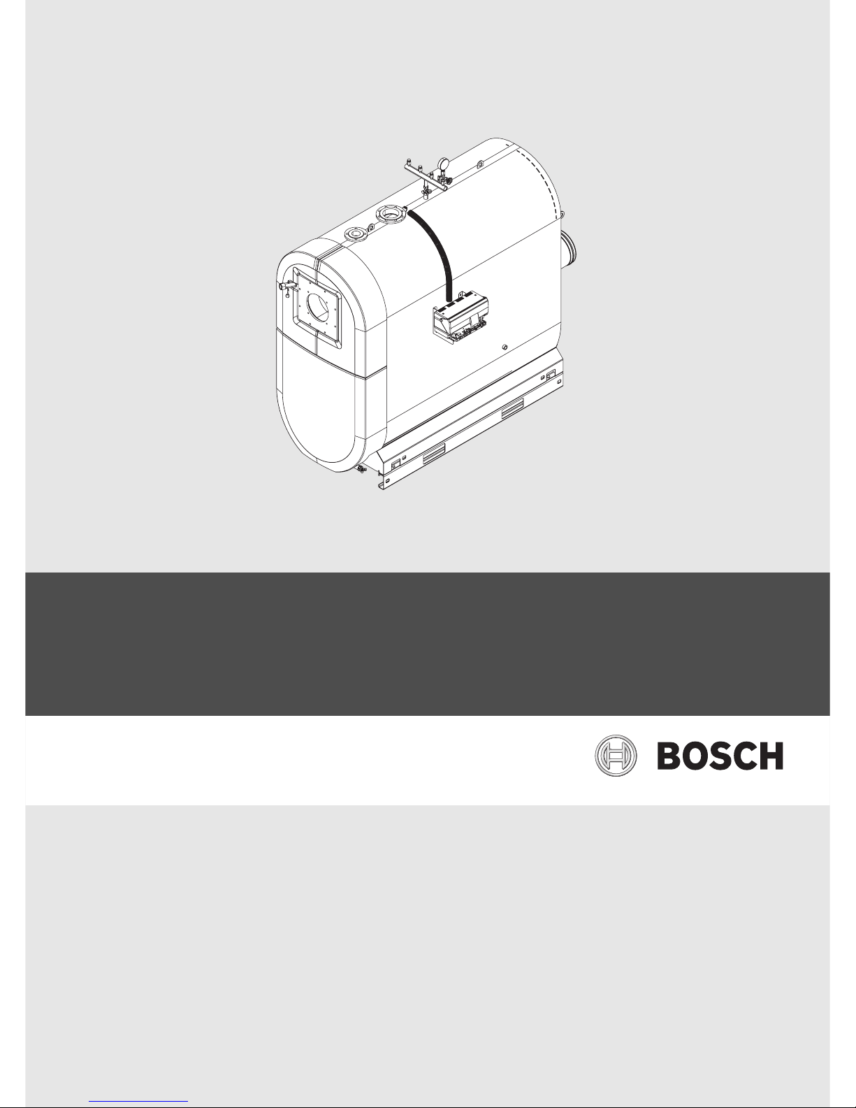
Floor standing condensing boiler
Uni Condens 6000F
6 720 648 053-00.2T
Output range 800 - 1200 kW
6 720 803 637 (2012/03) GB/AU
2 | Contents
Uni Condens 6000F6 720 803 637 (2012/03)
Contents
1 Key to symbols and safety instructions . . . . . . . . . . . . . . . . . . . 3
1.1 Explanation of symbols . . . . . . . . . . . . . . . . . . . . . . . . . 3
1.2 Safety instructions . . . . . . . . . . . . . . . . . . . . . . . . . . . . . 3
2 About the boiler . . . . . . . . . . . . . . . . . . . . . . . . . . . . . . . . . . . . . . 4
2.1 Type overview . . . . . . . . . . . . . . . . . . . . . . . . . . . . . . . . 4
2.2 Correct use . . . . . . . . . . . . . . . . . . . . . . . . . . . . . . . . . . . 4
2.3 Safety equipment . . . . . . . . . . . . . . . . . . . . . . . . . . . . . . 4
2.4 CE Declaration of Conformity . . . . . . . . . . . . . . . . . . . . 4
2.5 Scope of supply . . . . . . . . . . . . . . . . . . . . . . . . . . . . . . . 4
2.5.1 Accessories supplied . . . . . . . . . . . . . . . . . . . . . . . . . . . 4
2.5.2 Required accessories . . . . . . . . . . . . . . . . . . . . . . . . . . 4
2.6 Operating conditions . . . . . . . . . . . . . . . . . . . . . . . . . . 4
2.7 Suitable fuels . . . . . . . . . . . . . . . . . . . . . . . . . . . . . . . . . 5
2.8 Data plate . . . . . . . . . . . . . . . . . . . . . . . . . . . . . . . . . . . . 5
2.9 Tools, materials and auxiliary equipment . . . . . . . . . . . 5
2.10 Product description . . . . . . . . . . . . . . . . . . . . . . . . . . . . 5
2.11 Dimensions and specification . . . . . . . . . . . . . . . . . . . . 7
2.11.1 Dimensions . . . . . . . . . . . . . . . . . . . . . . . . . . . . . . . . . . . 7
2.11.2 Technical Data . . . . . . . . . . . . . . . . . . . . . . . . . . . . . . . . 8
2.11.3 Values for calculating the flue gas . . . . . . . . . . . . . . . . . 9
3 Information on installation and operation . . . . . . . . . . . . . . . . 9
3.1 Standards, regulations and directives . . . . . . . . . . . . . 9
3.2 Duty to obtain a permit and provide notification . . . . . 9
3.3 Burner selection and settings . . . . . . . . . . . . . . . . . . . . 9
3.4 Installation requirements . . . . . . . . . . . . . . . . . . . . . . 10
3.5 Combustion air quality . . . . . . . . . . . . . . . . . . . . . . . . . 10
3.6 Heating water quality . . . . . . . . . . . . . . . . . . . . . . . . . . 10
3.7 Using of antifreeze . . . . . . . . . . . . . . . . . . . . . . . . . . . . 10
3.8 Control unit settings . . . . . . . . . . . . . . . . . . . . . . . . . . 10
3.9 Hydraulic connection to the heating system . . . . . . . 12
3.10 Setting the minimum and maximum pressure
limiters . . . . . . . . . . . . . . . . . . . . . . . . . . . . . . . . . . . . . 12
3.11 Pressure maintenance . . . . . . . . . . . . . . . . . . . . . . . . . 13
4 Transport . . . . . . . . . . . . . . . . . . . . . . . . . . . . . . . . . . . . . . . . . . . 13
4.1 Moving the boiler with a forklift truck,
pallet truck or heavy duty rollers . . . . . . . . . . . . . . . . 13
4.1.1 Lifting the boiler with a crane . . . . . . . . . . . . . . . . . . . 13
4.1.2 Moving the boiler with a forklift truck . . . . . . . . . . . . . 14
4.1.3 Moving the boiler with heavy duty rollers . . . . . . . . . . 14
4.1.4 Moving the boiler with pallet trucks . . . . . . . . . . . . . . 14
5 Installation . . . . . . . . . . . . . . . . . . . . . . . . . . . . . . . . . . . . . . . . . . 15
5.1 Siting the boiler . . . . . . . . . . . . . . . . . . . . . . . . . . . . . . 15
5.2 Fitting sound insulation strips . . . . . . . . . . . . . . . . . . . 16
5.3 Levelling the boiler . . . . . . . . . . . . . . . . . . . . . . . . . . . . 16
5.4 Flue gas and water connections for heating system . 16
5.4.1 General requirements of the flue system . . . . . . . . . . 16
5.4.2 Fitting a sealing collar . . . . . . . . . . . . . . . . . . . . . . . . . 17
5.4.3 Connecting the boiler to the pipework . . . . . . . . . . . . 17
5.4.4 Information on condensate neutralisation . . . . . . . . . 17
5.4.5 Filling the boiler and checking connections for leaks 18
5.5 Opening and closing the combustion chamber door . 18
5.5.1 Opening and closing the combustion chamber door . 18
5.5.2 Refitting the door hinges . . . . . . . . . . . . . . . . . . . . . . . 18
5.6 Fitting the burner (accessory) . . . . . . . . . . . . . . . . . . 19
5.6.1 Fitting the burner plate . . . . . . . . . . . . . . . . . . . . . . . . 19
5.6.2 Fitting the burner to the burner plate . . . . . . . . . . . . . 20
5.7 Fitting and removing the front cover . . . . . . . . . . . . . 21
5.8 Fitting the control unit (accessory) . . . . . . . . . . . . . . 21
5.8.1 Fitting the control unit support and cable conduit . . 21
5.8.2 Fitting the control unit . . . . . . . . . . . . . . . . . . . . . . . . . 21
5.8.3 Making the electrical connection . . . . . . . . . . . . . . . . 22
5.9 Fitting temperature sensors . . . . . . . . . . . . . . . . . . . . 23
5.10 Routing the burner cable . . . . . . . . . . . . . . . . . . . . . . . 23
6 Commissioning . . . . . . . . . . . . . . . . . . . . . . . . . . . . . . . . . . . . . . 24
6.1 Flushing the heating system . . . . . . . . . . . . . . . . . . . . 24
6.2 Filling the heating system . . . . . . . . . . . . . . . . . . . . . . 24
6.3 Preparing the heating system for operation . . . . . . . 24
6.4 Commissioning the control unit and burner . . . . . . . . 24
6.5 Setting control unit parameters . . . . . . . . . . . . . . . . . 25
6.6 Commissioning report . . . . . . . . . . . . . . . . . . . . . . . . . 25
7 Shutting down . . . . . . . . . . . . . . . . . . . . . . . . . . . . . . . . . . . . . . . 26
7.1 Shutting down the heating system . . . . . . . . . . . . . . . 26
7.2 Shutting down the heating system in an emergency . 26
8 Inspection and maintenance . . . . . . . . . . . . . . . . . . . . . . . . . . . 26
8.1 General notes . . . . . . . . . . . . . . . . . . . . . . . . . . . . . . . . 26
8.2 Preparing the boiler for inspection and maintenance 26
8.3 Cleaning the boiler . . . . . . . . . . . . . . . . . . . . . . . . . . . . 26
8.3.1 Preparing the boiler for cleaning with brushes . . . . . 26
8.3.2 Cleaning the boiler with cleaning brushes . . . . . . . . . 26
8.3.3 Cleaning the reversing chamber . . . . . . . . . . . . . . . . . 27
8.3.4 Replacing the flue gas collector gasket . . . . . . . . . . . 28
8.3.5 Fitting the covers to the flue gas collector and
reversing chamber . . . . . . . . . . . . . . . . . . . . . . . . . . . 28
8.3.6 Wet-cleaning the boiler . . . . . . . . . . . . . . . . . . . . . . . . 28
8.4 Checking and correcting the water pressure . . . . . . . 28
8.4.1 When should you check the water pressure in the
heating system? . . . . . . . . . . . . . . . . . . . . . . . . . . . . . 29
8.4.2 Sealed unvented systems . . . . . . . . . . . . . . . . . . . . . . 29
8.4.3 Installations with automatic pressurisation units . . . 29
8.5 Inspection and maintenance reports . . . . . . . . . . . . . 30
9 Correcting a burner fault . . . . . . . . . . . . . . . . . . . . . . . . . . . . . . 31
10 Environmental protection/disposal . . . . . . . . . . . . . . . . . . . . . 32
11 System examples . . . . . . . . . . . . . . . . . . . . . . . . . . . . . . . . . . . . 32
11.1 Layout of the minimum equipment for technical safety
in accordance with EN 12828; operating temperature
≤ 105 °C; cut-out temperature (STB) ≤110 °C . . . . 32
Keyword index . . . . . . . . . . . . . . . . . . . . . . . . . . . . . . . . . . . . . . 33
Key to symbols and safety instructions | 3
6 720 803 637 (2012/03)Uni Condens 6000F
1 Key to symbols and safety instructions
1.1 Explanation of symbols
Warnings
Keywords indicate the seriousness of the hazard in terms of the
consequences of not following the safety instructions.
• NOTICE indicates that material damage may occur.
• CAUTION indicates that minor to medium injury may occur.
• WARNING indicates that serious injury may occur.
• DANGER indicates possible risk to life.
Important information
Additional symbols
1.2 Safety instructions
Danger through failure to consider your own safety in an emergency
such as a fire
B Never put your life at risk. Your own safety is paramount.
If you smell gas
B close the gas tap.
B Open the windows.
B Never operate electrical switches, including telephones, plugs or
doorbells.
B Extinguish all naked flames.
B No open fire.
B Never smoke.
B Never use lighters.
B Warn all occupants in the building, but do not ring doorbells.
B Leave the building and telephone your national gas emergency service
on 0800 111999 from an outside phone.
If you smell flue gas
B Switch off the appliance.
B Open windows and doors.
B Notify an authorised contractor.
Electric shock hazard
B Before carrying out any work on the heating system, disconnect the
heating system from the power supply across all poles. For example,
press the emergency stop switch outside the boiler room. It is not
enough to switch off at the boiler control unit.
B Safeguard the heating system against unintentional reconnection.
B Observe the country-specific rules and regulations when making the
electrical connection, commissioning, servicing and carrying out
maintenance.
Siting, conversion
An insufficient supply of air can result in dangerous escape of flue gas.
B Only have the boiler installed or modified by a competent person.
B Never modifiy any boiler components in contact with exhaust gas.
B With open flue appliances: Never cover or reduce the size of air vents
in doors, windows or walls. If draught-proof windows are fitted,
ensure there is an adequate ventilation.
B Ensure that the boiler installation room remains free from the risk of
frost.
B The heating system must be installed and operated in accordance
with the current: Statutory Instrument Laws, Gas Safety Regulations,
IEE Regulations, Building Regulations, Local Water By-Laws, Health &
Safety document 635 (The Electricity at Work Regulations) and any
other local requirements. Observe all European and local installation
standards, building regulations and the latest edition of the wiring
regulations. Chemically aggressive substances, can corrode the
appliance and invalidate any warranty.
Thermal disinfection
B Risk of scalding!
Monitor any operation with temperatures in excess of 60 °C.
Inspection and maintenance
B Recommendation for customers: Arrange a maintenance and
service contract with an authorised contractor, covering an annual
inspection and responsive maintenance.
B The user is responsible for the general and environmental safety of the
heating system.
B
Immediately correct all faults to prevent system damage!
B Use only genuine spare parts from the manufacturer. Losses caused
by the use of spare parts and accessories not supplied by the
manufacturer are excluded from the manufacturer's warranty.
Explosive and highly flammable material
B Never use or store highly flammable materials (paper, thinners, paints
etc.) near the boiler.
Combustion/room air
B Keep the combustion/ambient air free of corrosive substances (e.g.
halogenated hydrocarbons that contain chlorine or fluorine
compounds). This will help prevent corrosion.
B Keep the combustion air supply free of dust.
Instructing the customer
B Instruct the customer about how the boiler works and is operated.
B Inform customers that they must not carry out any modifications or
repairs.
Disposal
B Dispose of packaging in an environmentally responsible manner.
Warnings in this document are framed and identified by
a warning triangle which is printed on a grey
background.
Electrical hazards are identified by a lightning symbol
surrounded by a warning triangle.
Important information in cases where there is no risk of
personal injury or material losses is identified by the
symbol shown on the left. It is bordered by horizontal
lines above and below the text.
Symbol Meaning
B a step in an action sequence
Æ a reference to a related part in the document or to other
related documents
• a list entry
– a list entry (second level)
Table 1
4 | About the boiler
Uni Condens 6000F6 720 803 637 (2012/03)
2 About the boiler
2.1 Type overview
2.2 Correct use
The Uni Condens 6000F condensing boiler has been designed for hot
water heating systems in e.g. multiple dwelling units or for industrial
purposes.
Any gas burner to EN 676 and EN 267 can be used if its operating range
matches the boiler specification.
Only burners that have been tested and approved for electromagnetic
compatibility (EMC) may be used.
CFB control units are used with these boilers.
For further details on correct use Æ chapter 2.6, page 4, chapter 2.7,
page 5 and chapter 3, page 9.
2.3 Safety equipment
To ensure safe operation, the boilers must be equipped with the
following safety equipment:
• The level of safety equipment must comply with at least EN 12828.
• Also observe country-specific regulations if these specify further
requirements.
• Observe the maximum temperature high limit stat setting of 110 °C.
Equipment examples are included in the appendix, page 32. The
components comprising the safety equipment are available as
accessories.
2.4 CE Declaration of Conformity
The design and operation of this product conform to the applicable
European directives and supplementary national requirements.
Conformity has been demonstrated. You can ask for a copy of the
declaration of conformity. For this see the contact address at the back
cover of these instructions.
2.5 Scope of supply
The boiler is supplied with its full casing. The boiler front cover is
supplied separately and has to be fitted.
B On delivery, check that all packaging is in perfect condition.
B Check the delivery for completeness.
The standard delivery consists of:
• Boiler body with casing
• Front cover
2.5.1 Accessories supplied
The following accessories are included in the standard delivery and have
to be fitted:
• Control unit retainer and cable conduit (delivered inside the
combustion chamber)
• Sound insulation strip
• Siphon (delivered inside the combustion chamber)
• Insulating rings for blast tube (delivered inside the combustion
chamber)
• Technical documentation
2.5.2 Required accessories
The following accessories are not part of the standard delivery but are
required to operate the boiler:
• Burner
• Burner plate, drilled or undrilled
• Valve manifold
• Safety equipment
• Cleaning brushes
• Control unit
2.6 Operating conditions
Type Output
Uni Condens 6000F 800 kW, 1000 kW, 1200 kW
Table 2 Type overview
During installation and operation of the heating system,
observe all country-specific standards and guidelines.
Also observe the details on the boiler rating plate. These
are definitive and must be observed.
Set the burner to the combustion heating output QN
specified on the data plate as a maximum.
Conditions of use Unit Value
Maximum permissible temperature, high-limit safety cut-out °C 110
Maximum operating pressure bar 6
Maximum number of burner starts per annum 15 000
Table 3 Conditions of use
Operating conditions Uni Condens 6000F Uni Condens 6000F
Boiler water flow rate
None –
in conjunction with a CFB control unit for
modulating operation.
None –
in conjunction with a CFB control unit 930 for
constant boiler water temperatures or when
supplemented by a third party control unit.
Min. boiler water temperature
Operating interruption (total boiler shutdown)
Heating system control with mixing valve
Minimum return water temperature
Miscellaneous
1)2)
1) Maximum 15,000 burner starts per year In order not to exceed th e number of burner starts, observe the information on setting the control unit and burner in the
technical guide or installation instructions. If this value is still exceeded, please contact the manufactur er's customer service.
2) I n order not to exceed the maximum nu mber of burner starts per annum, t he manufacturer offers full commissioning for CFB control units with function modules, burner and
boiler as an alternative to 1). Any faults that may be present on site (e.g. incorrect sizing or setting of system components) must be corrected by the system installer.
1)
Table 4 Operating conditions
About the boiler | 5
6 720 803 637 (2012/03)Uni Condens 6000F
2.7 Suitable fuels
Permissible fuels
• Natural gas from the public gas supply in accordance with national
regulations with a total sulphur content < 50 mg/m
3
.
• LPG in accordance with national regulations with a content of
elementary sulphur < 1.5 ppm and volatile sulphur < 50 ppm.
The boiler must only be operated with the specified fuels. Only burners
that are suitable for the specified fuels may be used.
Observe the manufacturer's burner selection list and the burner
manufacturer's instructions.
2.8 Data plate
The data plate is fitted to the back of the boiler casing.
There you will find information such as the serial number, output and
approval details.
2.9 Tools, materials and auxiliary equipment
For the installation and maintenance of the boiler, standard tools are
required, as used for heating, gas, water and electrical installations.
2.10 Product description
The Uni Condens 6000F is a floor standing condensing boiler with a slim,
compact design and a small footprint thanks to the combustion chamber
being located at the top and the condensation heating surface being
located at the bottom. In the following, it is referred to as the Uni
Condens 6000F or the boiler.
The Uni Condens 6000F has two thermohydraulically separated return
connections for the high and low temperature circuits.
For the type-tested boiler sizes with internal condensing heat exchanger
and CE designation, the components that come into contact with hot gas
and condensate are made of stainless steel.
Equip the Uni Condens 6000F with a suitable burner.
Optional accessories can be found in the general catalogue.
The following are the main components of the Uni Condens 6000F are
(Æ Fig. 1, page 6):
• Boiler body [1] in conjunction with a burner
The boiler block transfers the heat produced by the burner to the
heating water.
• Thermally insulating casing
The boiler jacket and thermal insulation reduce energy losses.
• Control unit [8] (accessory)
The control unit monitors and controls all electrical boiler
components.
The combustion of biogas is not permitted.
If you contact the manufacturer with any questions about
this product, always provide the details on the data
plate. These details enable us to assist you specifically
and quickly.
NOTICE: System damage through the use of an
incorrect burner.
B Only use burners that meet the
technical requirements of the boiler
(Æ chapter 2.11, page 7).
6 | About the boiler
Uni Condens 6000F6 720 803 637 (2012/03)
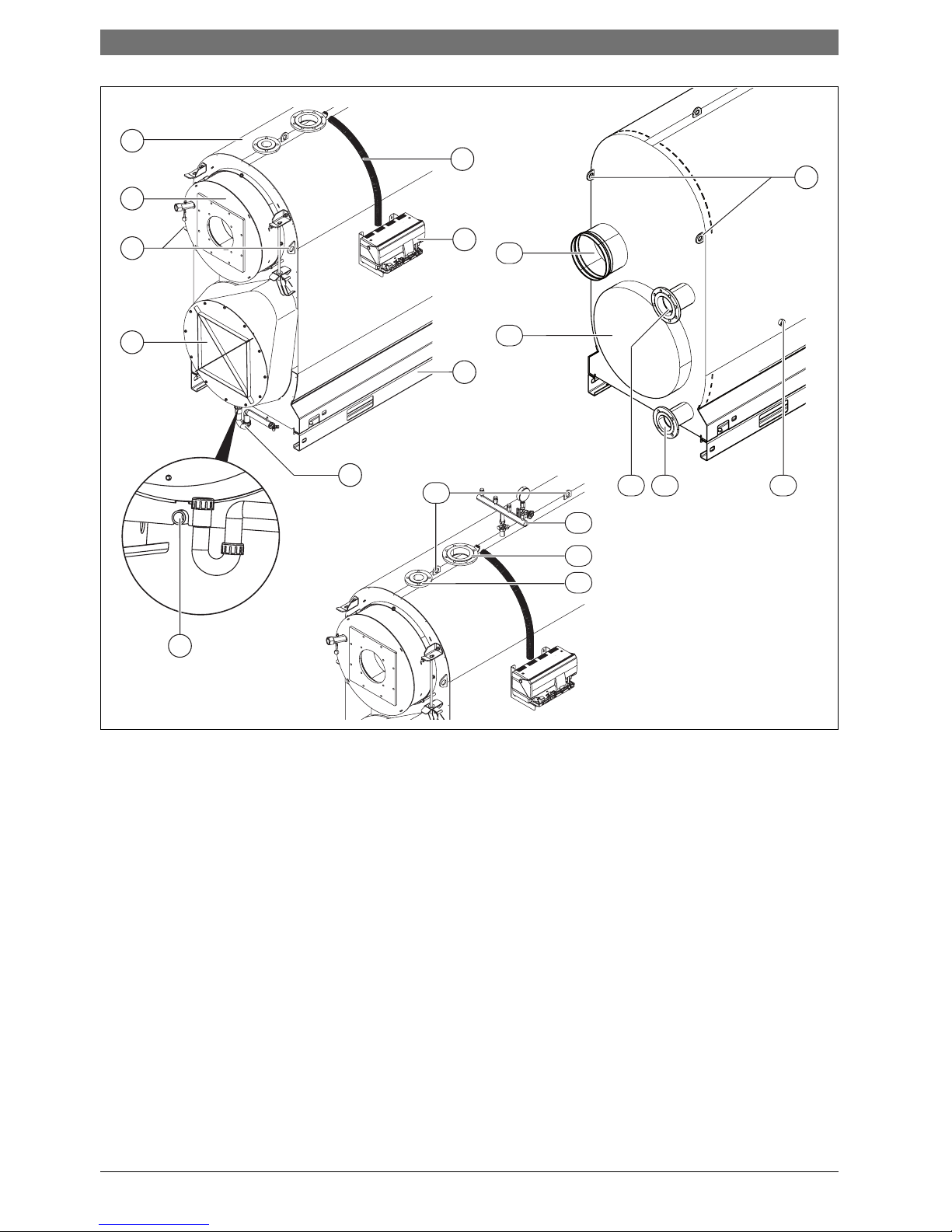
Fig. 1 Boiler overview
[1] Boiler body
[2] Combustion chamber door
[3] Locking lug to secure the load during transportation
(not for lifting the boiler)
[4] Flue gas collector
[5] Condensate drain, siphon
[6] Drain
[7] Base frame rail
[8] Control unit (accessory)
[9] Cable conduit
[10] Flue gas connection
[11] Inspection opening, reversing chamber
[12] Return 1 (RK1), low temperature return
(main return)
[13] Return 2 (RK 2), high temperature return
[14] Inspection opening on the water side (both sides)
[15] Flow safety connection
[16] Boiler flow
[17] Valve manifold (accessory)
[18] Lifting point
6 720 648 053-13.2T
5
6
16
17
13
1412
11
10
3
4
2
1
3
7
8
9
18
15
About the boiler | 7
6 720 803 637 (2012/03)Uni Condens 6000F
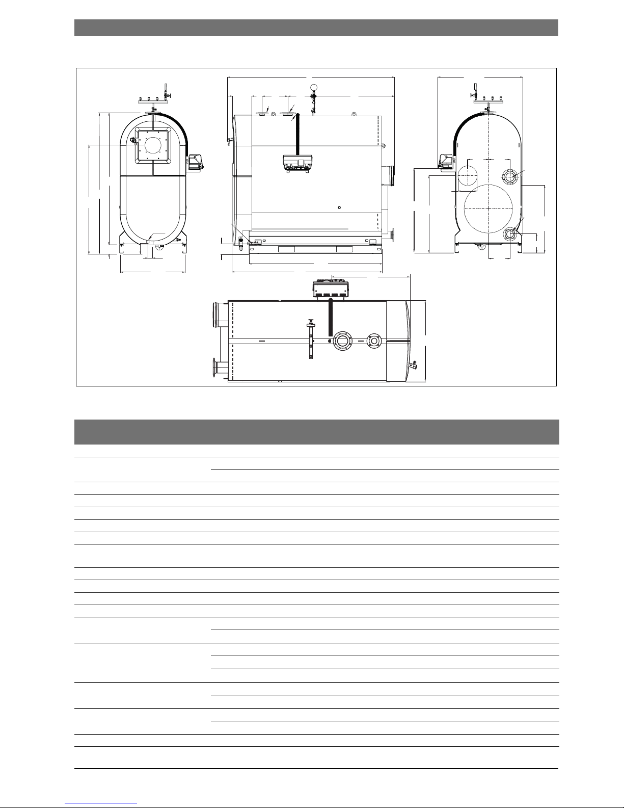
2.11 Dimensions and specification
Fig. 2 Boiler dimensions 800 kW, 1000 kW, 1200 kW
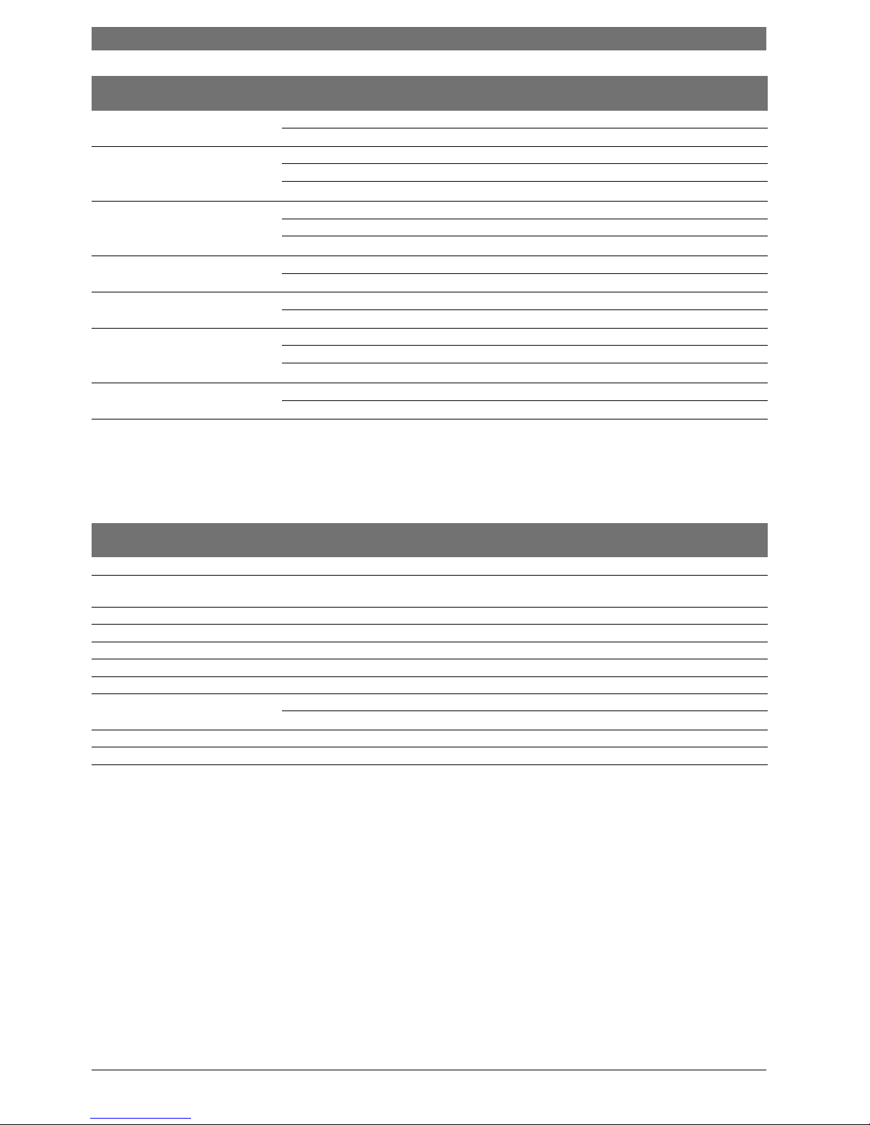
2.11.1 Dimensions
Abbreviation Unit Boiler type
800 1000 1200
Boiler size – kW 800 1000 1200
Length L mm 2545 2580 2580
L
K
mm 2360 2395 2395
Length incl. burner L
BR
mm Subject to burner
Width B mm 960 1040 1040
Width incl. control unit B
RG
mm 1220 1330 1330
Height H
K
mm 2014 2192 2192
Height of base frame
1)
H
GR
mm 140
Installation clearance control unit,
cable conduit
L
RG
mm 906 906 906
Installation height, control unit H
RG
mm 1300 1300 1300
Transport length
2)
∠ mm 2405 2455 2455
Transport width B mm 960 1040 1040
Transport height
1)
H
EB
mm 1874 2052 2052
Installation area base frame L
GR
mm 2060
B
GR
mm 960 1040 1040
Flue outlet Ø D
AAinternal
mm 253 303 303
H
AA
mm 1064 1193 1193
A
4
mm 299 348 348
Combustion chamber Length mm 1904 1954 1954
Ø
interior
mm 630 688 688
Combustion chamber door L
BT
mm 227
H
BT
mm 1508 1653 1653
Blast tube Minimum depth mm 210
Table 5 Boiler dimensions
6 720 648 053-18.2T
B
GR
H
AKO
A
7
H
EB
H
K
H
GR
H
BT
AKO
B
RG
H
AA
ØD
AAi
A
4
A
5
A
6
RK1
RK2
H
RK1
H
RG
H
RK2
VSL
VK
AAB
L
A
12
A
3
L
BT
A
EL
H
EL
L
GR
L
K
B
L
RG
8 | About the boiler
Uni Condens 6000F6 720 803 637 (2012/03)
2.11.2 Technical Data
Boiler flow
3)
ØVK
PN6
DN 100 125 125
A
2
mm 403 405 405
Boiler return flow
13)
ØRK1
PN6
DN 100 125 125
H
RK1
mm 1007 1148 1148
A
5
mm 320 380 380
Boiler return flow
3)
ØRK2
PN6
DN 80 100 100
H
RK2
mm 300 263 263
A
6
mm 320 390 390
Safety line flow
3)
ØVSL
PN16
DN 65
A
3
mm 400
Fittings manifold connection Ø AAB “ G1
A
1
mm 1200 1245 1245
Condensation outlet Ø AKO DN 40 40 40
H
AKO
mm 180 180 180
A
7
mm 71 70 70
Drain Ø EL “ R1
H
EL
mm 161 164 164
1) The base frame rails can be temporarily remo ved to reduce the transport height.
2) after the dismantling of the combustion chamber door
3) Flange to EN 1092-1
Unit Boiler type
800 1000 1200
Maximum flow temperature
1)
1) Safety limit (high limit safety cut-out). Maximum possible flow temperature = safety limit (high limit safety cut-out) − 18 K.
Example: Safety limit (high limit safety cut-out) = 100 °C, maximum possible flow temperature = 100 − 18 = 82 °C
°C 110
Permissible
operating pressure
bar 6
CE designation, product ID applied for
Weight (empty) net kg 1510 1760 1790
Operating weight
2)
2) Details excl. burner
gross kg 2440 2960 2980
Water content l 930 1200 1190
Hot gas volume l 1020 1310 1320
Combustion heat output
[Burner output QN (Hi)]
Full load, max. kW 742 928 1114
Partial load 30 % kW 223 278 334
Available draught Pa Subject to burner specification (50)
3)
3) Value in brackets is the recommended draught.
Pressure drop on the hot gas side mbar 6.4 6.5 7.5
Table 6 Technical Data
Abbreviation Unit Boiler type
800 1000 1200
Table 5 Boiler dimensions
Information on installation and operation | 9
6 720 803 637 (2012/03)Uni Condens 6000F
2.11.3 Values for calculating the flue gas
Values at system temperature 50/30 °C
Values at system temperature 80/60 °C
3 Information on installation and operation
3.1 Standards, regulations and directives
Observe all technical guidelines, country-specific regulations and
standards applicable to installation and operation. These include the
following:
• Local building regulations concerning the installation conditions.
• Local building regulations concerning the ventilation facilities and
chimney connection.
• Requirements for the electrical connection to the power supply.
• Technical rules of the gas supplier concerning the connection of the
gas burner to the public gas mains
• Regulations and standards concerning the safety equipment level of
wet heating systems.
The level of safety equipment must be at least compliant with EN
12828. Also observe country-specific regulations if these specify
further requirements.
3.2 Duty to obtain a permit and provide notification
• The local gas supply utility might need to be notified of and approve
the gas boiler installation
• Please note that regional approvals may be required for the flue
system and condensate connection to the public sewage system
• Prior to commencing installation, inform the relevant bodies and the
water board.
3.3 Burner selection and settings
The sizing and settings of the burner have a significant influence on the
service life of the heating system. Every load cycle (burner on/off)
causes thermal stress (loads on the boiler body). The number of burner
starts must therefore not exceed 15,000 per year.
The following recommendations and settings are designed to meet this
criterion (see also information on setting the control unit and the
hydraulic connection to the heating system). If you still cannot meet
this criterion, please contact the Bosch sales or service department.
• Set the burner output as low as possible. Set the burner to the
combustion heating output QN specified on the data plate as a
maximum. Never overload the boiler.
Unit Boiler type
800 1000 1200
Rated output, natural gas Full load kW 800 1000 1200
Partial load 30 % kW 243 303 364
CO
2
content Natural gas % 10
Flue gas temperature
1)
1) Calculated flue gas temperature for cross-sectional calculation to EN 13384 (a verage value across the series). The actual flue gas temperature may differ from this,
subject to burner setting and actual system temperature.
Full load °C 40
Partial load 30 % °C 30
Flue gas mass flow Full load kg/s 0.300 0.375 0.451
Partial load 30 % kg/s 0.089 0.112 0.134
Table 7 System temperature 50/30 °C
Unit Boiler type
800 1000 1200
Rated output, natural gas Full load kW 725 906 1090
CO
2
content Natural gas % 10
Flue gas temperature
1)
1) Calculated flue gas temperature for cross-sectional calculation to EN 13384 (a verage value across the series). The actual flue gas temperature may differ from this,
subject to burner setting and actual system temperature.
Full load °C 66 66 66
Partial load 30 % °C 36
Flue gas mass flow Full load kg/s 0.316 0.395 0.475
Partial load 30 % kg/s 0.095 0.118 0.142
Table 8 System temperature 80/60 °C
Regarding installation and operation of your heating
system, observe all relevant national standards and
guidelines.
The information on the data plate is binding and must be
observed.
The number of burner starts can be checked in the MEC
(Æ chapter 3.8, page 10).
10 | Information on installation and operation
Uni Condens 6000F6 720 803 637 (2012/03)
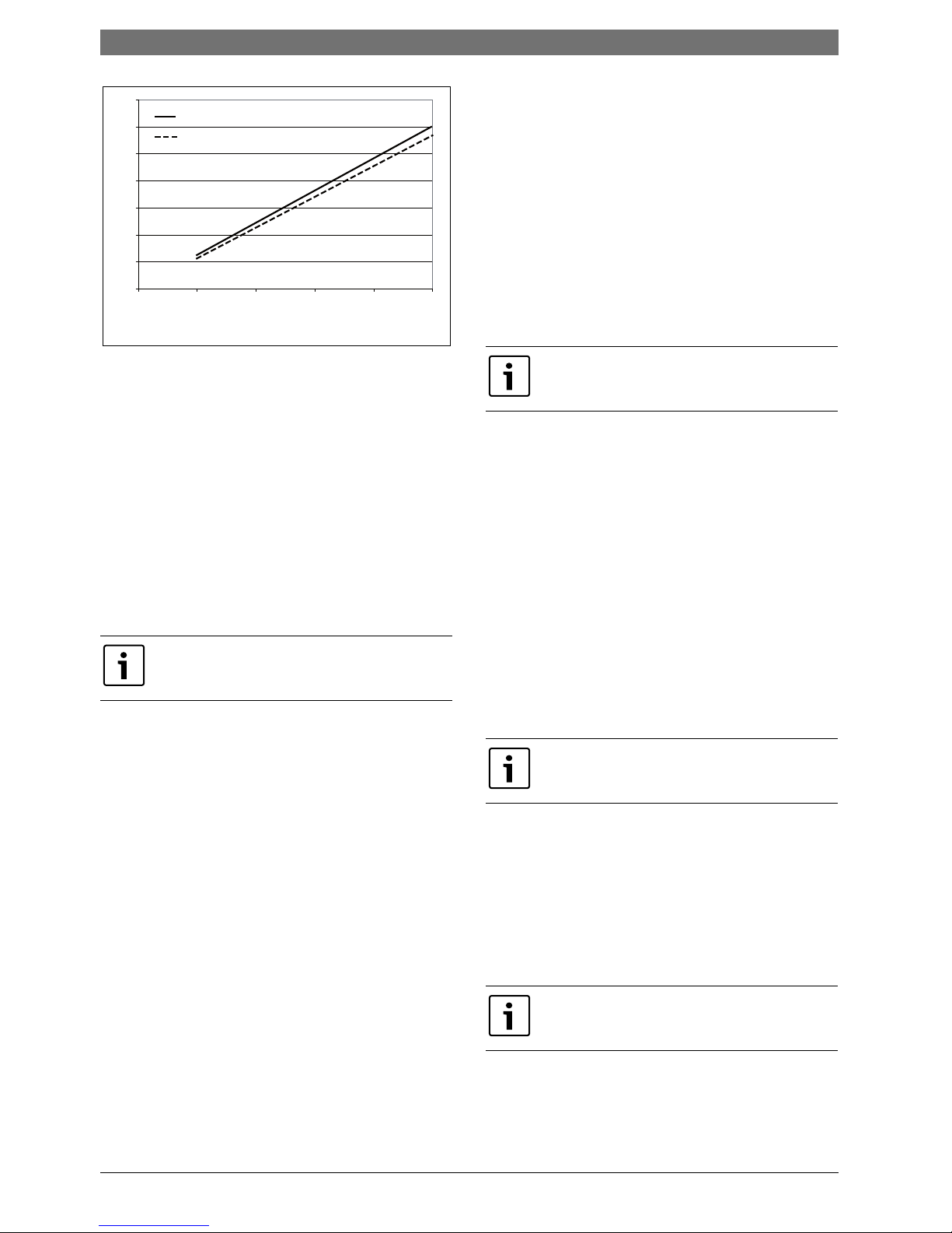
Fig. 3 Graph
• Take fluctuating net calorific values of the gas into account; check the
maximum value with the gas supply utility.
• Only use burners that are suitable for the specified fuels. Observe the
burner manufacturer's instructions.
• Burners must only be adjusted by a competent person.
3.4 Installation requirements
The installation room must meet the following conditions:
• In the boiler installation room, an ambient temperature of between 0
°C and 35 °C must be ensured (refer to the requirements of BS 6644).
• The installation room must be equipped with the required air vents.
• An adequate supply of fresh air must be ensured.
The ventilation to the plant room must meet the minimum requirements
stated in the building regulations. Please consider the additional free
ventilation for open flue appliances.
For boiler room ventilation sizes please refer to BS 6644 and IGE/UP/10
.
Regarding the size of the combustion air vent, it is essential that the
system installer seeks the agreement of the responsible approval or
building regulations body.
B Never install system components that could be damaged by frost near
the combustion air vents. If necessary, install a device to preheat the
ventilation air (e.g. a heater battery in the combustion air vent).
B Never position objects in front of these vents. Keep the combustion
air vents free at all times.
B Never store flammable materials or liquids in the immediate vicinity of
the heat source.
3.5 Combustion air quality
B Keep the supply of combustion air free of corrosive substances (e.g.
halogenated hydrocarbons that contain chlorine or fluorine
compounds).
This will help prevent corrosion.
B Never use or store chlorinated cleaning agents or halogenated
hydrocarbons (as contained in spray cans, solvents or cleaning
agents, paints and adhesives, for example) in the boiler room.
B Keep the combustion air supply free of dust.
B If building work is taking place in the installation room and creating a
lot of dust, shut the boiler down. A burner contaminated during
building work must be cleaned before commissioning.
3.6 Heating water quality
The quality of the fill and top-up water is an essential factor for increased
efficiency, functional reliability, long service life and for maintaining the
constant operational condition of a heating system. If the system is filled
with water that has a high calcium hardness, this will be deposited on the
heat exchanger surfaces and will obstruct the transfer of heat to the
heating water. As a result, the wall temperatures of the stainless steel
heat exchanger surfaces will increase and the thermal stress (loads on
the boiler body) will increase.
This is why the quality of the fill or top-up water must meet the conditions
stipulated in the operator's log provided and be recorded in this log.
The conditions for boilers > 600 kW require general water treatment
independent of the water hardness and the volume of fill and top-up
water.
3.7 Using of antifreeze
Antifreeze based on glycol has been used in heating systems for many
years, for example Antifrogen N manufactured by Clariant.
The use of other types of antifreeze should not be a cause for concern if
the product is comparable with Antifrogen N.
Observe the antifreeze manufacturer's instructions. Follow the
manufacturer's details regarding mixing ratios.
The specific thermal capacity of Antifrogen N antifreeze is lower than the
specific thermal capacity of water. To enable the transfer of the required
heat output, increase the required flow rate accor dingly. This s hould be
taken into account when sizing the system components (e.g. pumps)
and the pipework.
As the heat transfer medium has a higher viscosity and density than
water, take the higher pressure drop through the pipework and other
system components into account.
Check the resistance of all plastic or non-metallic components in the
system separately.
3.8 Control unit settings
The purpose of optimum control unit settings is to achieve long burner
run times and avoid rapid temperature changes in the boiler. Gentle
temperature changes result in a longer service life of the heating system.
The control strategy of the control unit must therefore be prevented
from becoming ineffective, i.e. through the boiler water regulator
switching the burner on and off.
B Maintain the minimum differential between the selected shutdown
temperature of the high limit safety cut-out, the temperature
regulator, the maximum boiler water temperature and the maximum
temperature demand (Æ table 9).
B Select set temperatures for the heating circuits that are as low as
possible.
B Start heating circuits (e.g. when starting up in the mornings) at 5-
minute intervals.
Take into account additional consumers of ventilation air
(e.g. compressors) when sizing.
6 720 648 053-28.1T
1400
1200
kW
1000
800
600
400
200
200 40 60 80 % 100
0
Kesselleistung bei 50/30° [kW]
Feuerungswärmeleistung [kW]
For boiler output 50/30° [kW]
Thermal output [kW]
Chemical additives that are not certified as safe for use
by the manufacturer must not be used.
The boiler needs to be operated with a Bosch CFB
control unit.
The maximum boiler water temperature can be selected
on the control unit (MEC) in the "Boiler parameters"
menu, under menu item "Max. shutdown temperature".
Information on installation and operation | 11
6 720 803 637 (2012/03)Uni Condens 6000F
Settings for boiler water regulator and maximum boiler water
temperature
The boiler water regulator is only designed to allow emergency operation
with an adjustable boiler water temperature if the control electronics
fail. In standard control mode, the function of the boiler water regulator
is provided by the maximum boiler water temperature. The maximum
boiler water temperature can be selected in the control unit in the "Boiler
parameters" menu, under menu item "Max. shutdown temperature".
Control unit settings
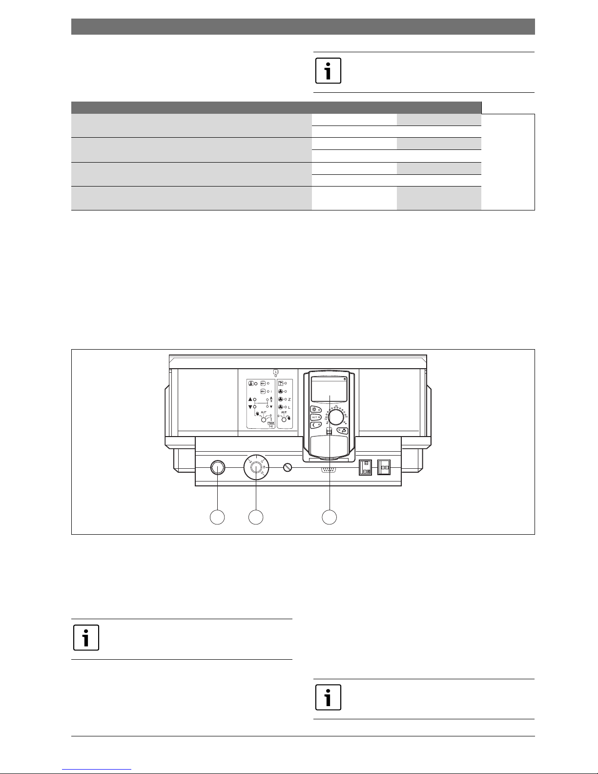
Fig. 4 Control unit settings
[1] High limit safety cut-out
[2] Temperature regulator
[3] MEC
B Select temperatures (Æ table 9, page 11) at high limit safety cut-out
[1] in the control unit and at temperature controller [2].
B Select the maximum boiler water temperature at the MEC [3].
Example DHW demand (where the 4000 series controls the DHW
system):
Sum of the set DHW temperature (60 °C) and parameter "Boiler rise"
(20 °C) in the "DHW" menu:
60°C+20°C =Maximum temperature demand 80°C
Example heating circuits (where the 4000 series controls the
heating circuits):
Add of the set temperature of the heating circuit with mixing valve with
the highest temperature required (70 °C) and parameter "Boiler rise"
(5 °C) in the "Heating circuit data" menu:
70 °C + 5 °C = Maximum temperature demand 75 °C
If the Bosch CFB control unit is used, burner modulation
in standard mode is not enabled for 3 minutes. Never
modulate upwards more quickly than this.
Adjustable parameter (max. temperature) CFB 910 CFB 840
High limit safety cut-out (STB)
1)
1) Set the high limit safety cut-out and temperature controller as high as possible, but ensure the settings are at least 5 K apart.
110 °C 110 °C
↑
minimum 18 K
↓
↓↑ minimum 5 K ↓↑
Temperature regulator (TR)
1)
105 °C 90 °C
↓↑ minimum 6 K ↓↑
Max. boiler water temperature 99 °C 84 °C
↓↑ minimum 7 K ↓↑
Max. temperature demand2) of HC3) and DHW
4)
2) Both temperature demands must always be at least 7 K below th e maximum boiler water temperature.
3) The temperature demand of heating circuits fitted with a mixing valve is composed of the set flow temperatur e and parameter "Boiler rise" in the heating circuit data
menu.
4) The temperature demand of DHW heating is composed of the set DHW temperature and parameter "Boiler rise" in t he DHW menu.
92 °C 77 °C
Table 9 Adjustable parameters CFB 910 and CFB 840
6 720 648 053-38.2T
1 2 3
80
The maximum temperature demand is not a value that is
directly selected. The maximum temperature demand is
composed of the set temperature and the rise.
All maximum temperature demands must always be 7 K
below the maximum selected boiler water temperature.
 Loading...