

Bosch TriTech DS950 Installation Instructions Manual
Installation Instructions
for the DS950 Series
TriTech
1.0 Specifications
• Dimensions (HxWxD): 5 in. x 2.8 in. x 2.2 in.
• Input Power: 9 VDC to 15 VDC, 22 mA DC nominal
• Standby Power: No internal standby battery.
• Alarm Relay: Silent operating Form "C" reed relay.
• Tamper: Normally Closed (with cover on).
• Temperature Range: -40°F to +120°F (-40°C to +49°C).
• Microwave Frequency:
DS950: 10.525 GHz (UL Listed)
DS950A: 10.687 GHz (Export only, not UL
DS950B: 9.9 GHz (Export only, not UL Listed))
• Coverage:
Broad (standard): 50 ft. by 50 ft. (15 m by 15 m)
Long Range (optional): 100 ft. by 10 ft. (30 m by 3 m)
• Internal Pointability: +2° to –10° Vertical, ±10° Horizontal.
• Options: B328 Gimbal Mount Bracket, B335
NOTE: Use of a bracket may reduce range and increase dead zone
Reading Bosch Security Systems, Inc. Product Date Codes
•
For Product Date Code information, refer to the Bosch Security
Systems, Inc. Web site at: http://www.boschsecurity.com/
datecodes/.
®
PIR/Microwave Intrusion Detectors
(12.7 cm x 7.1 cm x 5.6 cm)
(up to 52 mA DC during walk testing,
stored alarms, or trouble conditions).
Use only an Approved Limited Power
Source.
Standby power must be provided by
an Approved Limited Power Source.
For each hour of standby time
needed, 22 mAh is required. A
minimum of 4 hrs. (88 mAh) is
required for UL Listed requirements.
Contacts rated 3 W, 125 mA,
28 VDC maximum for DC resistive
loads; and protected by a 4.7 Ω,
0.5 W resistor in the common "C"
leg of the relay. To be connected to a
SELV (Safety Extra-Low Voltage) circuit
only. Do not use with capacitive or
inductive loads.
Contacts rated at 28 VDC, 125 mA
max. To be connected to a Safety
Extra-Low Voltage (SELV) circuit only.
Connect tamper circuit to 24-hour
protection circuit.
For UL Listed requirements, the
temperature range is +32°F to +120°F
(0°C to +49°C), indoor use.
Listed)
Low Profile Swivel Mount Bracket,
B338 Ceiling Mount Bracket, OLR92
Long Range Barrier Lens, TC6000
Test Cord
areas.
• Compliance: This device complies with Part 15 of the FCC Rules
and with RSS-210 of Industry and Science Canada. Operation is
subject to the following two conditions:
(1) this device may not cause harmful interference, and
(2) this device must accept any interference received,
including interference that may cause undesirable
operation.
Changes or modifications not expressly approved by Bosch
Security Systems can void the user’s authority to operate the
equipment.
2.0 Installation Considerations
NOTE: The DS950 is not recommended for installations containing
pets or small animals. Use the DS820 or DS835 for such
installations.
• Never install the detector in an environment that causes an alarm
condition in one technology. Good installations start with the LED
OFF when there is no target motion. It should never be left to
operate with the tri-color LED in a constant or intermittent green,
yellow, or red condition.
• Point the unit away from outside traffic (roads/alleys).
NOTE: Microwave energy will pass through glass and most
common non-metallic construction walls.
• Avoid installations where rotating machines (e.g. ceiling fans)
are normally in operation within the coverage pattern. Point the
unit away from glass exposed to the outdoors and objects that
may change temperature rapidly.
NOTE: The PIR detector will react to objects rapidly changing
temperature within its field-of-view.
• Eliminate interference from nearby outside sources.
3.0 Mounting
• Select a location likely to intercept an intruder moving across the
coverage pattern. The surface should be solid and vibrationfree. Mounting height range is 6 to 8 feet (1.8 to 2.4 m).
Recommended mounting height is 7.5 feet (2.3 m).
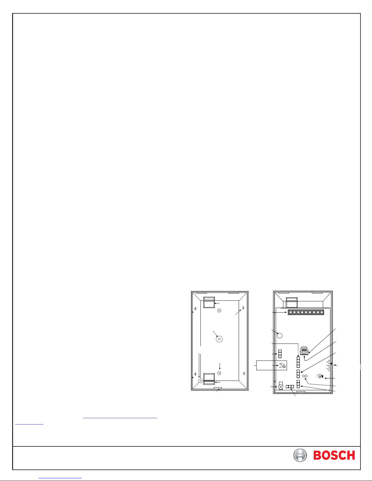
• Remove the cover. Insert a flathead screwdriver into the locking
tab hole at the bottom front of the detector. Pull the cover up and
forward.
Wire
Entrances
Corner Mount
Knockout (4)
Bracket Mount
Knockout
Ver tica l Adj ust
Screw Mount
Surface Mount
Knockout (2)
Wire
Entrances
Cover Tab and
Locking Screw Hole
• Remove the circuit board from the base. Loosen the Vertical
Adjust Screw and slide the circuit board down, then out.
• Break away the appropriate thin-wall wire entrance and mounting
hole coverings in the base.
Terminal
Strip
Tri-col or
LED
Motion Monitor
and Anti-Mask
Selection Pins
LED
On/Off
Pins
Memory
Jumper
*
Verti cal
Adjust
Screw
*= Cut only if using the Memory
or 1 Day Motion Monitor features.
Walk test before cutting.
On
Off
_
NO C NC T T M TR
+
30
1
Off
INT
STD
Microwave Noise Voltage Pins
MW
Look Down
Lens
Look Down
Mask
PIR
Sensitivity
Selection Pins
0°
- 4°
Vertical Adjust
- 8°
Scale
Microwave
Range Adjust
Trouble
Memory
PIR Noise
Voltage Pins
• Using the base as a template and aligning it so that the detector
will be mounted with the terminal block at the top and the PIR
lens at the bottom, mark the location of the mounting holes on
the mounting surface. Pre-start the mounting screws.
• Route wiring as necessary. Route to the rear of the base and
through the wire entrance. Make sure all wiring is unpowered
before routing.
• Securely attach the base to the mounting surface.
• Return the circuit board to the base and tighten the Vertical Adjust
Screw.
4.0 Wiring
Only apply power after all connections have been
made and inspected. Do not coil excess wiring inside
CAUTION
NOTE: Input power must use only an Approved Limited Power
detector.
Source. Alarm and Tamper Contacts to be connected to a
SELV (Safety Extra-Low Voltage) circuit only.
Alarm
6.0 Feature Selection
On
6.1 LED On/Off Pins
The ON position allows operation of the tri-color LED. If
LED indication is not desired after setup and walk tests are completed,
place in the OFF position. The OFF position does not prevent the LED
from indicating supervision trouble conditions.
Off
6.2 Memory Operation and Microwave Inhibit
To use the alarm memory function, cut the Memory Jumper (after
walk testing). When this jumper is cut, the Microwave Inhibit function
is also activated. This eliminates microwave transmissions during
disarmed periods.
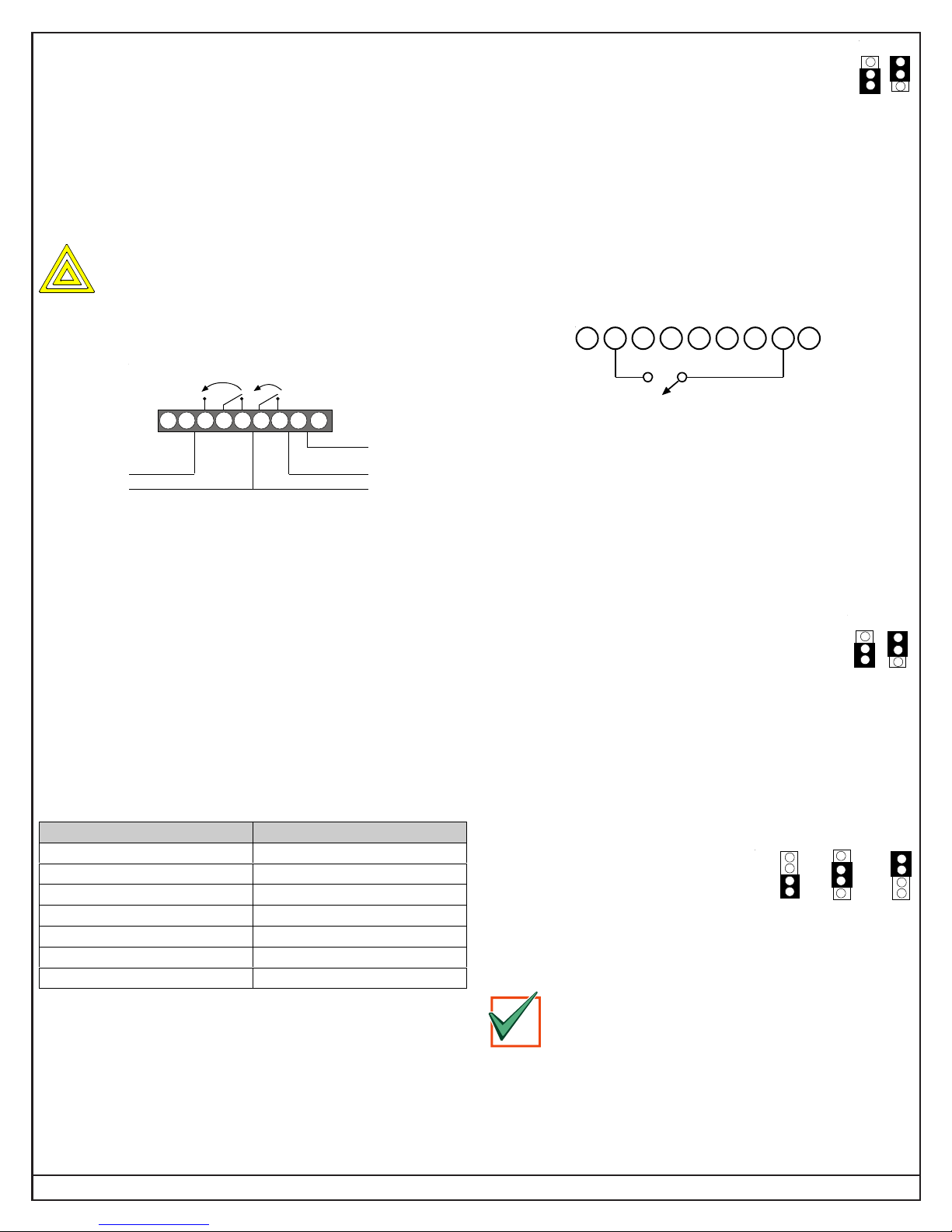
To supply voltage, connect a switch between Terminals 2 and 8 on
the detector’s T-strip as shown here:
1234
567
8 9
1 2 3 4 5 6 7 8 9
–+NO C NC T T M
9-15 VDC
Input
Alarm Relay
Ta mp e r
TR Trouble
Memory
Input
• Terminals 1 (–) & 2 (+): Voltage limits are 9 to 15 VDC. Use no
smaller than #22 AWG (0.8mm) wire pair between the detector
and the power source.
• Terminals 3, 4, & 5: Alarm relay (reed) contacts rated 3 W,
125 mA, 28 VDC maximum for DC resistive loads and protected
by a 4.7 Ω, 0.5 W resistor in the common "C" leg of the relay. Use
Terminals 4 and 5 for Normally Closed circuits.
NOTE: Do not use with capacitive or inductive loads.
• Terminals 6 & 7: Tamper contacts rated at 28 VDC, 125 mA.
• Terminal 8: Memory. Refer to Section 6.0 Feature Selection.
• Terminal 9: Trouble. Solid State output.
NOTE: Plug the wire entrance hole with the foam plug provided
after all wiring connections have been made.
5.0 LED Operation
The chart below shows tri-color LEDs the detector uses to indicate
the alarm and supervision trouble conditions.
LED CAUSE
Steady red Unit alarm
Steady yellow Microwave activation (walk test)
Steady green PIR activation (walk test)
Flashing red Warm-up period after power-up
Flashing red (2 pulse sequence) Motion monitor time-out
Flashing red (3 pulse sequence) Anti-mask detection
Flashing red (4 pulse sequence) MW or PIR self-test failure
Flashing red 2 - 4 = The LED flashes 2-4 times a cycle.
NOTE: During walk testing, the LED will light for the first technology
(microwave or PIR) and then light red to indicate a detector
alarm. The LED will not indicate activation of the second
technology by lighting its color.
NOTE: If switched voltage (between 9 and 15 volts) is supplied
from another source, such as an alarm panel, then wiring
must also be provided from Terminal 1 of the detector to the
negative (-) side of the alternate source.
When voltage is applied to Terminal 8, any stored alarm is cleared
from memory and it is ready to store the next alarm.
When voltage is removed from Terminal 8 (disarmed condition), the
tri-color LED is enabled, and a stored alarm will cause the tri-color
LED to turn ON red continuously. If there is no stored alarm, the tricolor LED and relay will respond to PIR only; they will activate only
during a present alarm.
NOTE: The Motion Monitor and Anti-Mask pins must
be in the OFF position in order for the
INT
Microwave Inhibit feature to work.
6.3 PIR Sensitivity Selection Pins
STD
For selection, place the plug across the pins marked STD for Standard
or INT for Intermediate mode.
• Standard Sensitivity: The recommended setting for maximum
false alarm immunity. Tolerates environmental extremes on this
setting.
• Intermediate Sensitivity: The recommended setting for any
location where an intruder is expected to cover only a small portion
of the protected area. Tolerates normal environments on this
setting. This setting will improve
your intruder catch performance.
6.4 Motion Monitor/Anti-Mask
Off
1
30
Pins
By enabling Motion Monitor and the Anti-Mask feature with the selection
pins, a choice of Off or 1 day or 30 days may be chosen for Motion
Monitor.
If 1-day Motion Monitor is selected, the memory
feature must be enabled by cutting the memory
jumper. The Motion monitor timer will be suspended
IMPORTANT
To suspend the 1-day motion monitor timer when the control panel is
armed, apply a switched voltage to Terminal 8 as shown in the
beginning of Section 6. This will prevent the motion monitor from
timing out when no movement is anticipated. When the switched
voltage is removed from Terminal 8, the motion monitor timer will
continue to count down until motion is detected.
when the detector is in night (armed) mode.
Page 2 © 2011 Bosch Security Systems, Inc. DS950 Series Installation Instructions
 Loading...