

Bosch TRANSFLOW j-45096 Operation Manual
Transmission Cooling System
J-45096
Operation Manual
TRANSFLOW Transmission Cooling System Service Tool J-45096 1
Safety Precautions
WARNING: TO PREVENT PERSONAL INJURY AND/OR DAMAGE TO EQUIPMENT:
• ALLOW ONLY QUALIFIED PERSONNEL TO OPERATE THE UNIT. Before operating the unit, read and follow the instructions and warnings in this manual.
If the operator cannot read English, operating instructions and safety precautions must be read and discussed in the operator’s native language.
• Do not use this equipment in a manner not specified by the manufacturer.
• Wear eye protection that meets OSHA standards.
• Correctly connect power supply cord to the vehicle 12V DC battery and
chassis ground.
• Use only GM Approved
• Do not overfill the supply vessel with automatic transmission fluid (ATF).
• A minimum of 90 psi of shop air is required to operate this machine.
• Operate and store this machine in an upright position.
• Disconnect the machine from the shop air supply at the conclusion of each
day to ensure correct operation of the water separator.
• Dispose of waste ATF in accordance with all applicable federal, state and
local requirements.
Dexron VI® Automatic Transmission Fluid.
2 TRANSFLOW Transmission Cooling System Service Tool J-45096

Table of Contents
Introduction
Glossary of Terms .............................................................................................................. 2
Equipment Specifications ................................................................................................... 2
Component Location Overview
Front View .......................................................................................................................... 3
Rear View ........................................................................................................................... 3
Control Panel ..................................................................................................................... 4
Set-Up Instructions
Initial Set-Up Instructions ................................................................................................... 5
Waste Vessel Drain Set Up ................................................................................................ 6
Power Up ........................................................................................................................... 8
TransFlow Self-Test ............................................................................................................ 9
Operating Instructions
Machine Set-Up ............................................................................................................... 11
Flow Test/Flush Operation ............................................................................................... 12
Waste Oil Removal .............................................................................................................. 15
Maintenance Instructions
Service Parts ................................................................................................................... 16
Accessories ..................................................................................................................... 16
Transmission Oil Cooler (T.O.C.) Adapters....................................................................... 17
Useful Information/Hepful Hints ....................................................................................... 18
Troubleshooting ................................................................................................................... 19
Warranty Information/Technical Support .................................................... Inside Back Cover
TRANSFLOW Transmission Cooling System Service Tool J-45096 1

Introduction
The TransFlow machine is a product designed to measure the transmission oil cooler (T.O.C.) oil
ow capability and to remove contaminated oil from the T.O.C. system after a transmission repair.
Measuring the transmission cooler system oil ow rate determines if the cooler meets the current
GM ow rate specication.
Glossary of Terms
ATF Automatic Transmission Fluid, Dexron VI® ATF or equivalent
GPM Gallons per Minute
T.O.C. Transmission Oil Cooler
Equipment Specifications
Component Specification
TransFlow Part Number J-45096
Power Supply Operating Voltage 11 Volts DC–16 Volts DC
Air Pressure 90 PSI (Minimum)
Minimum ATF Temperature 65° F
Supply Vessel Capacity 32 Quarts US
Waste Vessel Capacity 34 Quarts US
Flow Rate 0.5-2.5 gpm
2 TRANSFLOW Transmission Cooling System Service Tool J-45096
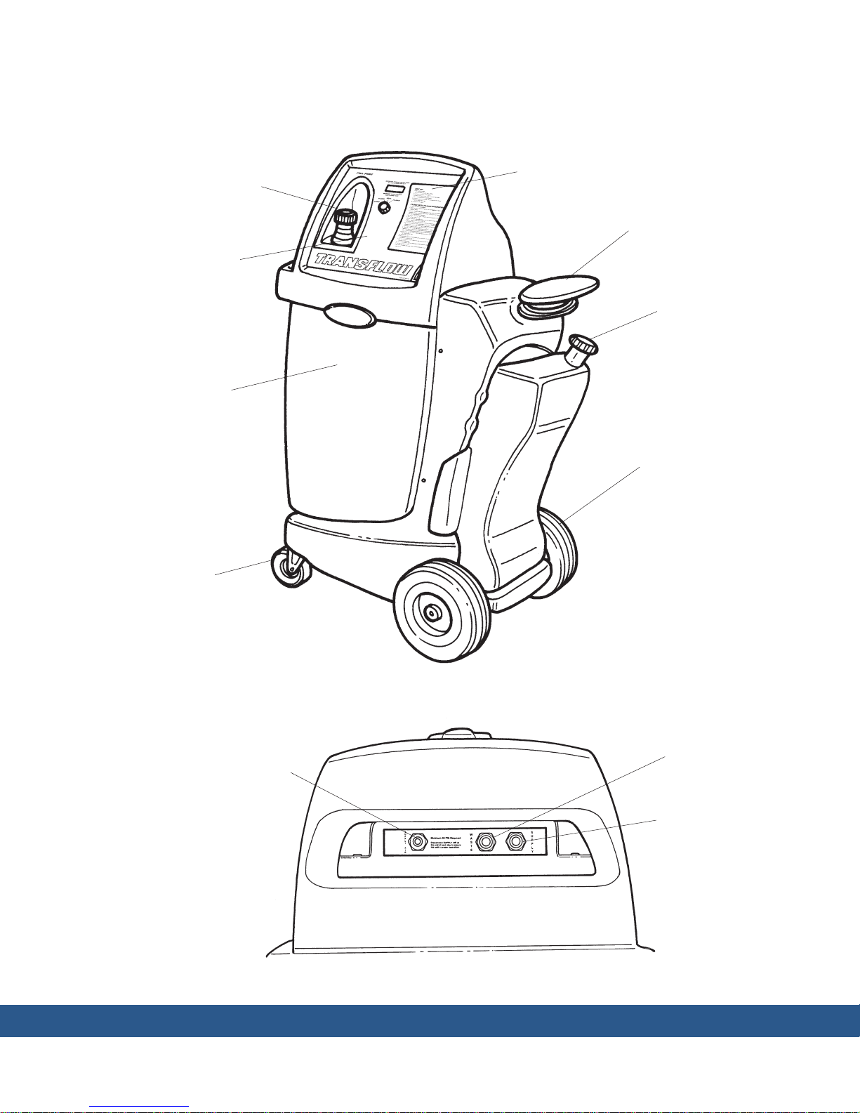
Component Location Overview
ATF Fill
Port
Control Panel
Polypropylene
Cabinet for
Durability
Front View
Operation
Instructions
Convenient Handle
for Cord and
Hose Storage
Waste Oil
Vessel
Large Wheels for
Mobility across
Air Lines, Power
Cords, and Grates
Locking Casters
Shop Air
Supply
Rear View
Waste Oil
Inlet
Supply Oil
Outlet
TRANSFLOW Transmission Cooling System Service Tool J-45096 3
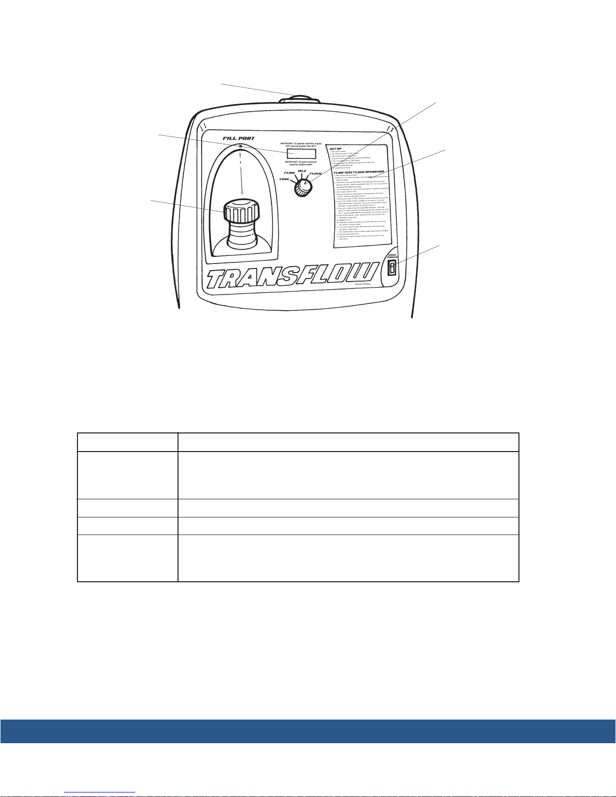
Red light indicates when
machine is pressurized
LCD Display
Window
ATF Fill
Port
Control Panel
Main Function
Switch
Operating
Instructions
Main Power
Switch
Main Function Switch
The following table provides a quick reference for the main function switch positions:
Switch Position
Flush
Idle
Flow
Code
Allows pressurized automatic transmission uid with a high pressure pulse
of air to ush the contaminated oil from the T.O.C. If any debris exists in
the T.O.C., it will also be ushed when the machine is in this mode.
Standby mode; zero pressure applied to the T.O.C. and cooler lines.
Tests the ow rate of the T.O.C. and cooler lines.
Provides a seven-character, encrypted warranty code following a successful ow test. Note: The ow test must run for a minimum of 8–10 seconds
and be above 0.5 gpm for a code to be generated.
Description
4 TRANSFLOW Transmission Cooling System Service Tool J-45096
Set-Up Instructions
Initial Set-Up
1. Remove the TransFlow unit from the packaging.
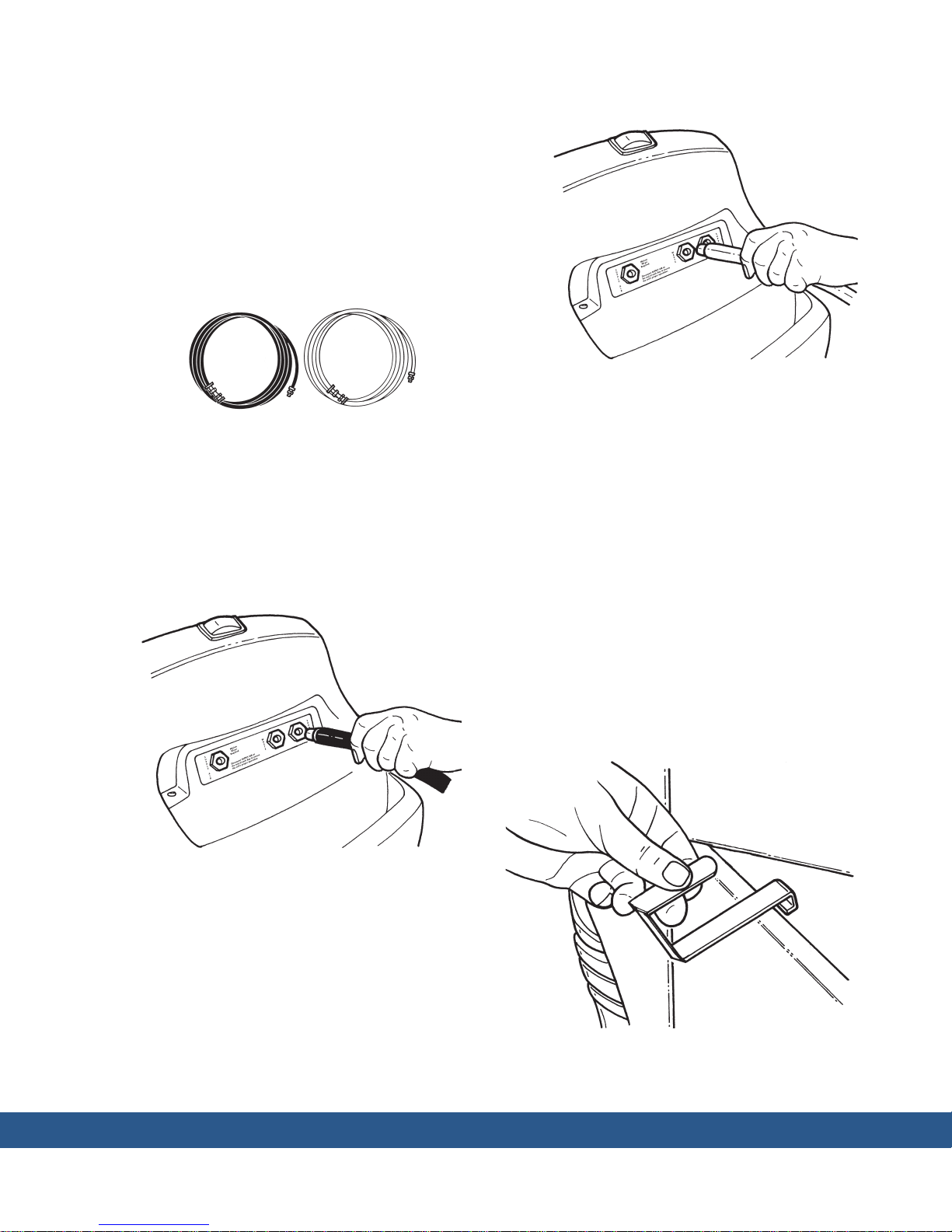
2. Locate the accessory package and remove
the black supply hose and the clear waste
hose. See Figure 1. Also locate and remove
the two hose storage brackets.
Figure 1
3. Apply Loctite® 565 sealant (supplied) to the
threaded male end of the black supply hose.
4. Thread the supply hose clockwise onto the
TransFlow tting, located on the rear panel
of the TransFlow unit, marked SUPPLY. See
Figure 2.
Figure 3
8. Tighten the tting.
9. Apply Loctite® 565 thread sealant to the
threads of an air line quick-disconnect tting
(customer supplied).
10. Thread the quick-disconnect tting clockwise onto the TransFlow tting, located on
the rear panel of the TransFlow unit, marked
Supply AIR.
11. Tighten the quick-disconnect tting.
12. Open the door on the unit by using a screwdriver to turn the fasteners counterclockwise
about a quarter-turn. Snap one hose storage
bracket over the top of the door as shown
in Figure 4, and position the other hose
storage bracket 8"–10" away from the rst.
Figure 2
5. Tighten the tting.
6. Apply Loctite® 565 thread sealant to the
threaded male end of the clear waste hose.
7. Thread the waste hose clockwise onto the
TransFlow tting, located on the rear panel
of the TransFlow unit, marked WASTE. See
Figure 3.
Figure 4
TRANSFLOW Transmission Cooling System Service Tool J-45096 5

Set-up Instructions contd.
The waste and supply hoses can be stored on
these brackets when not in use. See Figure 5.
Figure 5
IMPORTANT: Dispose of the waste ATF in
accordance with all applicable federal, state
and local requirements.
1. If draining from the bottom of the waste
vessel, rst remove the drain tting cap plug
by turning the cap plug counterclockwise
while supporting the hexagonal drain tting.
Note: Be sure to support the hexagonal drain
tting while removing the cap plug to prevent
potential damage to equipment. See Figure
1.
Waste Vessel
Cap Plug
Waste Vessel Drain Set Up
Before TransFlow is used, it is recommended to
consider a draining strategy for the waste ATF
that will be stored in the waste vessel on the
side of TransFlow. The waste vessel may be
drained through a tting at the bottom or by
removing the waste vessel cap at the top of the
vessel to use an oil transfer pump to evacuate the
oil. This section describes a procedure to outt
the drain tting at the bottom of the waste vessel
with a standard 1/2" pipe to make it more
convenient for you to adapt to. It is your responsibility to either cap this 1/2" pipe once installed,
or to adapt a tting or hose to it to allow you to
drain the waste vessel.
Hexagonal
Drain Fitting
Figure 1
2. Locate the drain support bracket and screws
from the accessory kit. Place the drain support bracket underneath the plastic lip of the
left side base of the TransFlow machine (or
towards front of TransFlow). The drain support bracket should be at against the inside
plastic lip and the hole in the drain support
bracket should be clearly below the plastic.
6 TRANSFLOW Transmission Cooling System Service Tool J-45096
 Loading...