

Bosch TR8500, TR8500 15/18 DESOAB, TR8500 24/27 DESOAB, TR8500 21/24 DESOAB Installation Instructions Manual
Montageanleitung
Installation instructions
Notice de montage
Montagehandleiding
Instrukcja montażu
Montaj Kılavuzu
TR8500
TR8500 15/18 DESOAB | 21/24 DESOAB | 24/27 DESOAB
6 720 876 028 (2017/07)DIV

Inhaltsverzeichnis
Inhaltsverzeichnis 1 Bestimmungsgemäßer Gebrauch
1 Bestimmungsgemäßer Gebrauch . . . . . . . . . . . . . . . . . . . . . . . 2
2 Sicherheitshinweise . . . . . . . . . . . . . . . . . . . . . . . . . . . . . . . . . . 2
3 Montageanleitung . . . . . . . . . . . . . . . . . . . . . . . . . . . . . . . . . . . . 3
3.1 Montage . . . . . . . . . . . . . . . . . . . . . . . . . . . . . . . . . . . . . . 3
4 Technische Daten. . . . . . . . . . . . . . . . . . . . . . . . . . . . . . . . . . . . . 4
5 Sonderzubehör . . . . . . . . . . . . . . . . . . . . . . . . . . . . . . . . . . . . . . . 4
6 Umweltgerecht entsorgen . . . . . . . . . . . . . . . . . . . . . . . . . . . . . 4
Dieses Gerät ist nur für den privaten Haushalt und das häusliche Umfeld
bestimmt.
2 Sicherheitshinweise
Die Montageanleitung bitte sorgfältig durchlesen, danach handeln
und aufbewahren! Bei Weitergabe des Gerätes diese Montageanleitung beilegen.
• Das Gerät nur von einem Fachmann anschließen und in Betrieb
nehmen lassen.
• Das Gerät wie in Text und Bild beschrieben montieren und bedienen.
Wir übernehmen keine Haftung für Schäden, die durch Nichtbeachtung dieser Anleitung entstehen.
• Beiliegende Wasseranschlussstutzen unbedingt verwenden und wie
im Beiblatt angegeben montieren. Sicherstellen, dass im Kaltwasserzulauf ein Rückschlagventil eingebaut wird.
• Dieses Gerät ist für den Gebrauch bis zu einer Höhe von 2 000 m
über dem Meeresspiegel bestimmt.
• Das Gerät nur in einem frostfreien Raum installieren und lagern (Restwasser).
WARNUNG:
Stromschlaggefahr!
Schalten Sie im Fehlerfall sofort die Netzspannung ab!
Vor dem Öffnen des Gerätes die Stromzufuhr zum Gerät unterbrechen.
Bei einer Undichtigkeit am Gerät sofort die Kaltwasserleitung schließen.
• Die gesetzlichen Vorschriften des jeweiligen Landes, des örtlichen
Elektrizitäts-Versorgungsunternehmens und des Wasserwerkes
müssen eingehalten werden.
• Der Durchlauferhitzer ist ein Gerät der Schutzklasse I und muss an
den Schutzleiter angeschlossen werden.
VORSICHT:
Geerdete Wasserleitungen können das Vorhandensein eines Schutzleiters vortäuschen.
• Das Gerät muss dauerhaft an festverlegte Leitungen angeschlossen
werden. Der Leitungsquerschnitt muss der zu installierenden
Leistung entsprechen.
• Zur Erfüllung der einschlägigen Sicherheitsvorschriften muss installationsseitig eine allpolige Trennvorrichtung vorhanden sein.
Die Kontaktöffnung muss mindestens 3 mm betragen.
• Das Gerät ist nur für den geschlossenen (druckfesten) Betrieb geeignet.
• Armaturen müssen für den Betrieb mit geschlossenen (druckfesten)
Durchlauferhitzern zugelassen sein.
• Das Gerät kann an eine Kaltwasserleitung angeschlossen oder mit
vorgewärmtem Wasser (Solaranlage) betrieben werden. Dazu technische Daten und Sonderzubehör beachten.
• Der spezifische Wasserwiderstand darf nicht unter 1 300 Ωcm liegen.
Den Wasserwiderstand beim örtlichen Wasserversorger erfragen.
• Das Gerät ist für den Anschluss an DVGWgeprüfte Kunststoffrohre
geeignet.
• Das elektrische Anschlusskabel vor der Montage spannungslos
machen und die Wasserzuleitung absperren!
• Den Elektroanschluss erst nach dem Wasseranschluss durchführen.
• In der Rückwand nur die Öffnungen herstellen, die für die Montage benötigt werden. Bei erneuter Montage müssen die unbenutzten Öffnungen wasserdicht verschlossen werden.
• Spannungsführende Teile dürfen nach der Montage nicht mehr berührbar sein.
2
TR8500 – 6 720 876 028 (2017/07)

Montageanleitung
• Keine Scheuermittel oder anlösende Reinigungsmittel verwenden.
• Keinen Dampfreiniger benutzen.
Herzlichen Glückwunsch zum Kauf dieses Geräts aus unserem Hause
BOSCH. Sie haben ein hochwertiges Produkt erworben, das Ihnen viel
Freude bereiten wird.
3 Montageanleitung
Diese Montageanleitung beschreibt einen Durchlauferhitzer mit AquaStop.
• Montieren Sie das Gerät wie im Bildteil beschrieben. Die Bildseiten
finden Sie in der Mitte der Anleitung. Beachten Sie die Hinweise
im Text.
3.1 Montage
Auspacken/Haube abnehmen (Bild 1)
• Gerät auspacken und auf Transportschäden kontrollieren.
Liegt ein Schaden vor, Gerät nicht anschließen.
• Lieferumfang kontrollieren: Gerät, Montagesatz mit Beiblatt, Montageanleitung, Gebrauchsanleitung.
• Verpackung und Altgerät umweltgerecht entsorgen.
• Beim Abnehmen der Haube beachten: Die Haube ist durch einen zentralen Verschluss hinter der Serviceklappe fixiert.
Montagevorbereitung (Bild 2)
Wichtig: Nur den beiliegenden Montagesatz verwenden.
Die mitgelieferten Wasseranschlussstutzen müssen unbedingt eingebaut werden!
• Wasserzuleitung absperren. Der elektrische Anschluss (Anschlusskabel) muss spannungsfrei sein. Sicherungen herausdrehen oder
ausschalten.
• Die Wasseranschlussstutzen nach der Anleitung auf dem Beiblatt
montieren.
• Die Anschlussleitung kann wahlweise oben (X) oder unten (Y) eingeführt werden.
• Die Rückwand muss an der vorgesehenen Stelle auf dem Kaltwasserstutzen aufliegen (Bild 2, 8.).
• Auf waagrechte und lotrechte Ausrichtung achten. Die Neigung des
Gerätes darf 1° (2 %) in alle Richtungen nicht überschreiten!
Wandmontage (Bild 3)
• Die Tülle muss das Anschlusskabel eng umschließen. Wird sie bei der
Montage beschädigt, müssen die Löcher wasserdicht verschlossen
werden.
• Die Netzanschlussklemme kann oben (X) oder unten (Y) montiert
werden. Die Ummantelung des Anschlusskabels muss mindestens
40 mm in das Gerät hineinragen.
• Der Wandabstand ist variabel. So können Unebenheiten der Wand ausgeglichen werden. Bei einem Wandabstand von 8–16 mm die Distanzhalter einsetzen und die Verlängerung montieren (Bild 3, 3.–6.).
• Das Gerät muss fest an der Wand montiert werden. Befestigen Sie
es gegebenenfalls an den unteren Stellschrauben (Bild 3, 7.).
• Das Gerät muss entlüftet werden. Dazu Warmwasserhahn ganz
öffnen und das Gerät 1 Minute lang spülen.
Elektroanschluss/Montage (Bild 6)
• Vor Anschluss der Leitungen an die Netzanschlussklemme die Leistung mit dem Leistungsumschalter einstellen: nominale Leistung
links, reduzierte Leistung rechts (Bild 6, 1.) und die eingestellte Leistung am Typenschild markieren.
• Die Leitungen an der Netzanschlussklemme festschrauben.
• Sicherheitsbegrenzer einschalten (Bild 6, 3.).
• Haube montieren (Bild 6, 4.–7.).
Installationshinweis
• Die Installation nicht-steckerfertiger Geräte ist vom jeweiligen
Netzbetreiber oder von einem eingetragenen Fachbetrieb vorzunehmen, der Ihnen auch bei der Einholung der Zustimmung des
jeweiligen Netzbetreibers für die Installation des Gerätes behilflich ist.
Inbetriebnahme (Bild 7)
Das Gerät stimmt mit IEC 61000-3-12 überein.
Erstinbetriebnahme
• Sicherungen einschalten.
• Temperatur einstellen.
• Startspülung: Warmwasserhahn ganz öffnen und mindestens
1 Minute lang Wasser beziehen. Aus Sicherheitsgründen beginnt
das Gerät erst danach mit dem Heizen.
Tipp: Startet das Gerät aufgrund von zu geringem Durchfluss nicht, Perlator, Brausekopf oder Ähnliches zum Starten entfernen und Vorgang
wiederholen.
• Erklären Sie dem Benutzer die Bedienung des Gerätes.
Zusatzinformationen (Bild 8)
• Erreicht das Gerät aufgrund von zu geringem Wasserleitungsdruck
in Ihrer Hausinstallation keinen genügenden Durchfluss, entfernen
Sie den Durchflussbegrenzer (Bild 8, 1.–3.).
• Vorrangschaltung für die Kombination mit Elektro-Speicherheizgeräten: Für den Betrieb mit Vorrangschaltung ist ein spezielles Lastabwurfrelais BZ 45L21 (Sonderzubehör) erforderlich. Andere, bereits
vorhandene Lastabwurfrelais, ausgenommen elektronische Lastabwurfrelais, können Fehlfunktionen aufweisen (Bild 8, Schaltplan).
• Bei Betrieb mit dem Lastabwurfrelais muss die Regelungselektronik
kodiert werden. Die Kodiernase auf der Elektronik entfernen
(Bild 8, 4.).F
Wasseranschluss (Bild 4/5)
• Vor dem Wasseranschluss das AquaStop Verbindungsrohr in die Tülle
einführen (Bild 5, 7.). Die Tülle muss das Verbindungsrohr dicht abschließen.
• Den Wasseranschluss vornehmen, anschließend die Kaltwasserzuleitung öffnen.
• Beim Verschrauben der Anschlüsse darauf achten, dass der
AquaStop vertikal ausgerichtet ist.
• Die Grifflächen zusammendrücken und die Transportsicherung nach
rechts abziehen (Bild 5, 10.).
TR8500 – 6 720 876 028 (2017/07)
3

Technische Daten
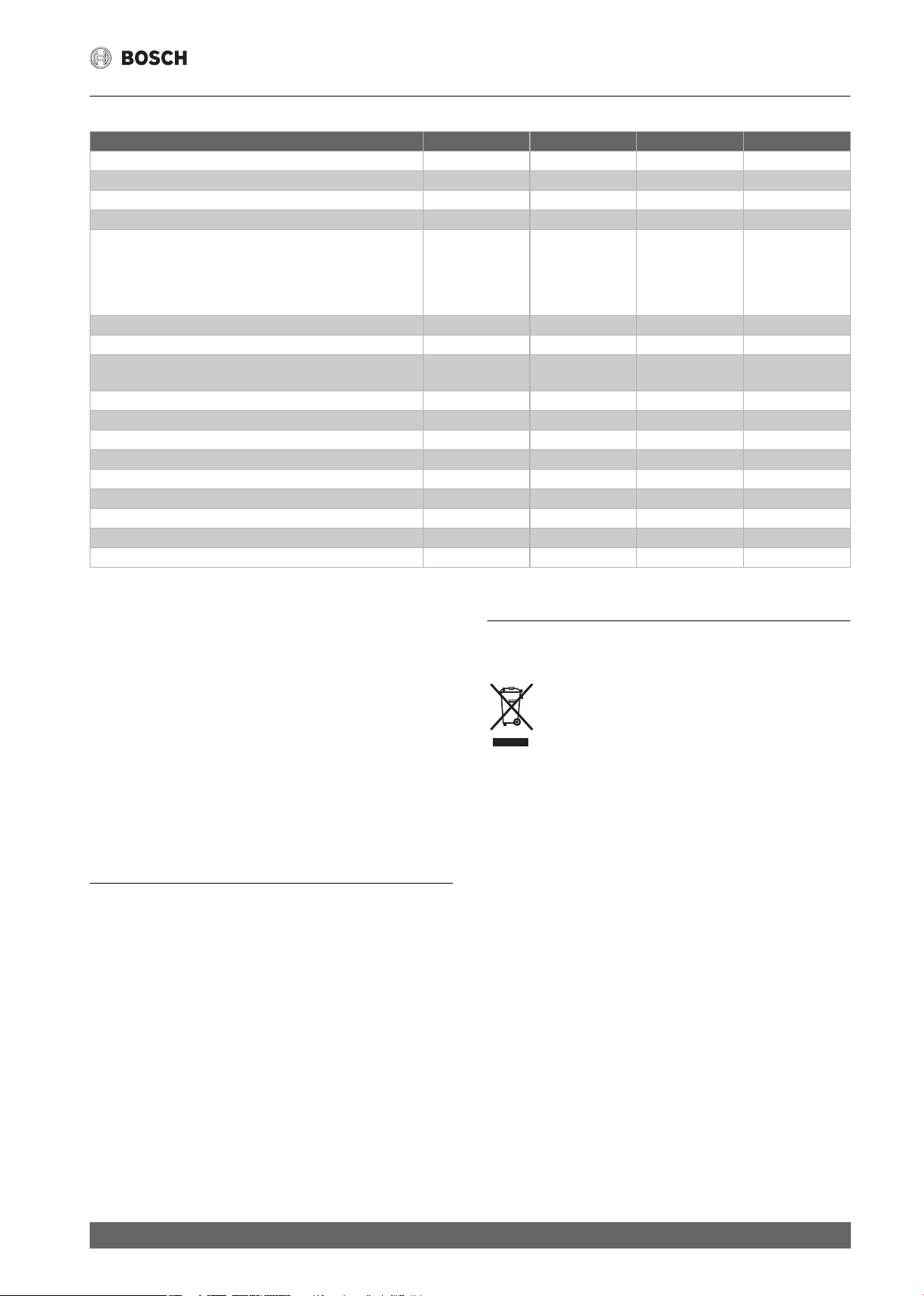
4 Technische Daten
15/18 DESOAB 21/24 DESOAB 24/27 DESOAB
Nennleistung [kW] 15/18 21/24 24/27
Nennspannung [V] 400 400 400
Absicherung [A] 25/32 32/40 40
Mindestens Leitungsquerschnitt * [mm2] 2,5/4 4 6
Warmwassermenge bei Nennleistung
bei Temperaturerhöhung von
12 °C auf 38 °C (ohne Durchflussmengenbegrenzer)
12 °C auf 38 °C (mit Durchflussmengenbegrenzer)
12 °C auf 60 °C
Einschaltmenge [l/min] 2,5 2,5 2,5
Einschaltfließdruck ** [MPa (bar)] 0,009 (0,09) 0,009 (0,09) 0,009 (0,09)
Einsatzbereich in Wässern
Spezifischer elektrischer Widerstand bei 15 °C
Nenndruck [MPa (bar)] 1,0 (10) 1,0 (10) 1,0 (10)
Maximal zulässige Zulauf-Temperatur [°C] 60 60 60
Maximale Netzimpedanz am Anschlussort [Ω] 0,067/0,104 0,067/0,104 0,067/0,104
Energieeffizienzklasse A A A
Lastprofil SSS
Jahresenergieverbrauch [kWh] 478 479 479
Täglicher Stromverbrauch [kWh] 2,199 2,204 2,207
Schallleistungspegel [dB] 15 15 15
Warmwasserbereitungs-Energieeffizienz [%] 38,6 38,5 38,5
* In Abhängigkeit von der Verlegeart können auch größere Leitungsquerschnitte erforderlich sein.
** Hierzu kommt noch der Druckabfall an der Mischbatterie.
[l/min]
[l/min]
[l/min]
[Ωcm] ≥ 1 300 ≥ 1 300 ≥ 1 300
8,1/9,8
6,5
4,4/5,3
11,6/13,0
8,7
6,2/7,1
13,0/14,6
9,3
7,1/7,9
Solarbetrieb
Das Gerät erwärmt bereits vorgewärmtes Wasser auf max. 60 °C. Überschreitet der Kaltwasserzulauf die Temperatur von 55 °C, wird das Wasser nicht weiter erwärmt.
Wichtig: Die Kaltwasser-Zulauftemperatur darf nicht höher als 55 °C
sein!
Wird die Kaltwasser-Zulauftemperatur von 60 °C überschritten, löst das
Gerät eine Sicherheitsabschaltung aus. Deshalb muss in der Hausinstallation ein Thermostatvormischer (z. B. Sonderzubehör BZ 45T20) eingebaut sein, der die Kaltwasser-Zulauftemperatur auf max. 55 °C durch
Zumischung von Kaltwasser begrenzt.
Abmessungen (Bild 9)
5 Sonderzubehör
• Rohrbausatz BZ 45U20 zur Verwendung des Gerätes als Untertisch-
gerät
• Vorrangschalter (Lastabwurfrelais) BZ 45L21 für den Betrieb mit
Vorrangschaltung
• Montageset BZ 45K23 für Aufputzinstallation
• Thermostatvormischer BZ 45T20 für den Einbau in die Hausinstalla-
tion bei Nutzung von vorgewärmtem Wasser.
6 Umweltgerecht entsorgen
Dieses Gerat ist entsprechend der europäischen Richtlinie 2012/19/EU über Elektro- und Elektronikaltgeräte (waste electrical and electronic equipment – WEEE)
gekennzeichnet.
Die Richtlinie gibt den Rahmen für eine EU-weit gültige
Rücknahme und Verwertung der Altgeräte vor.
Über aktuelle Entsorgungswege bitte beim Fachhändler informieren.
Änderungen vorbehalten.
4
TR8500 – 6 720 876 028 (2017/07)
Table of Contents
Table of Contents
1 Intended Use . . . . . . . . . . . . . . . . . . . . . . . . . . . . . . . . . . . . . . . . .5
2 Safety information . . . . . . . . . . . . . . . . . . . . . . . . . . . . . . . . . . . .5
3 Installation instructions . . . . . . . . . . . . . . . . . . . . . . . . . . . . . . .6
3.1 Installation . . . . . . . . . . . . . . . . . . . . . . . . . . . . . . . . . . . . 6
4 Technical data . . . . . . . . . . . . . . . . . . . . . . . . . . . . . . . . . . . . . . . .7
5 Special accessories . . . . . . . . . . . . . . . . . . . . . . . . . . . . . . . . . . .7
6 Environmentally-friendly disposal. . . . . . . . . . . . . . . . . . . . . . . 7
1 Intended Use
This appliance is intended for domestic use and the household
environment only.
2 Safety information
Please read this installation instruction manual carefully, then
act accor dingly! Store for future reference. These installation
instructions must be included when transferring this appliance
to a new owner.
• The appliance may only be connected and put into operation
by a qualified professional.
• Install and operate the appliance as described in the text and illustrations. We do not accept liability for damage resulting from failure
to heed these instructions.
• The supplied water connection nozzles must be used and installed
as shown in the supplementary sheets. Make sure that a check valve
is installed in the cold water supply line.
• This appliance is intended for use up to an altitude of 2,000 m above
sea level.
• The appliance may only be installed and stored in a frost-free room
(due to residual water).
WARNING:
Risk of electric shock!
Switch off the mains voltage supply immediately if a fault occurs.
Disconnect the power supply before opening the appliance.
Immediately shut off the cold water supply to the appliance
should it leak.
• The statutory regulations of the respective country, as well as those
of the local electricity and water suppliers, must be adhered to.
• The continuous-flow heater is a Class I appliance and must be
connected to the protective earth.
CAUTION:
Earthed water pipes may give the appearance of a connected protective
earth.
• The appliance must be permanently connected to installed pipes.
The conductor cross-section must comply with the installed
appliance power.
• To guarantee compliance to relevant safety regulations, an all-pole
separator must be fitted during installation. The contact opening
must be at least 3 mm.
• The continuous-flow heater is only suitable for closed (pressurised)
operation.
• The tap and outlet fittings must be approved for operation with
closed (pressurised) continuous-flow heater systems.
• The continuous-flow heater can be operated with cold or pre-warmed
water (for example, from a solar energy unit water supply). Observe
the technical data and the special accessories for this purpose.
• The water’s specific electrical resistivity must not be less than
1,300 Ωcm. Ask the local water utility company regarding the
electrical resistivity of the water.
• The continuous-flow heater is suitable for connection to DVGWtested plastic pipes.
• Disconnect the electrical connection cable from the supply and
shut off the water supply before connecting the appliance!
• Connect the water supply and then connect the electrical supply.
• Only make the openings which are required for installation on the rear
of the appliance. If the appliance is reinstalled, the unused openings
must be provided with watertight sealing.
TR8500 – 6 720 876 028 (2017/07)
5

Installation instructions
• Do not touch electrically live parts after installation.
• Do not use aggressive or abrasive cleaning detergents!
• Do not use a steam cleaner.
Congratulations on purchasing this BOSCH appliance. You have
acquired a top-quality product, which will give you a lot of enjoyment.
3 Installation instructions
These installation instructions describe a continuous-flow heater
with AquaStop.
• Install the appliance as shown in the illustrations. The illustrations
can be found in the centre of the instruction manual. Observe the
instructions in the text.
3.1 Installation
Unpacking/Removing the cover (Fig. 1)
• Unpack the appliance and check for transport damage. If any components are damaged, then do not connect the appliance.
• Check that your appliance contains all components included in the scope
of delivery: appliance, installation set with supplementary sheets,
installation instructions, operating instructions.
• Please dispose of the packaging and the old appliance
in an environmentally-friendly manner.
• When removing the cover, please note the following: The cover is
fastened by a central closure behind the service flap.
Preparations for installation (Fig.2)
Important: Only use the supplied installation set. The supplied water
connection nozzles must be installed!
• Shut off water supply. The electrical connection (connection cable)
must be disconnected from the power supply. Unscrew the fuse
or switch off the circuit breaker.
• Install the water connection nozzles according to the instructions
on the supplementary sheet.
• The electrical connection cable can either be guided in at the top (X)
or bottom (Y).
• The rear panel must lie against the cold water connection nozzle in
the position provided for such (Fig. 2, 8.).
• Pay attention to horizontal and perpendicular alignment. The
appliance must not tilt out more than 1° (2 %) in any direction!
Wall mounting (Fig. 3)
• The grommet must tightly surround the connection cable. If it is damaged during mounting, the openings must be provided with watertight sealing.
• The electrical supply terminal can be fitted at the top (X) or bottom
(Y). The sheath of the connection cable must extend for at least
40 mm into the appliance.
• The distance to the wall is variable. You can compensate for any
unevenness of the wall’s surface. With a distance to the wall of 8–16 mm,
insert the spacer and install the extender (Fig. 3, 3.–6.).
• The appliance must be mounted securely on the wall. If necessary,
attach it at the lower adjustable screws (Fig. 3, 7.).
• Press the grip surfaces together and pull out the transport protection
attachment to the right (Fig. 5, 10.).
• The appliance must be vented. To do so, open the warm water tap
fully and flush out the appliance thoroughly for 1 minute.
Electrical connection/Mounting (fig. 6)
• Set the power using the power selector switch before connecting
the wires to the mains connection terminal: Nominal output power
left, reduced output right (Fig. 6, 1.) and the set output marked
on the ratings plate.
• Screw the wires tightly into the mains connection terminal.
• Switch on the safety limiter (Fig. 6, 3.).
• Install the cover (Fig. 6, 4.–7.).
Installation note
• The installation of non plug-in ready appliances must
be undertaken by the respective utility operator or by a qualified
specialist company, who can also assist you when you are
requesting the approval of the utility company for installation of
the appliance.
Startup (Fig. 7)
The device is compliant to IEC 61000-3-12.
First start-up
• Switch on the fuses.
• Setting the temperature.
• Initial rinsing: Open the warm water tap fully and allow water to flow
for at least 1 minute. Only then (for safety reasons) will the appliance
begin to heat.
Tip: Should the appliance not start because of a reduced flow-rate,
remove the perlator, shower head or similar before start and repeat the
process.
• Explain the operation of the appliance to the user.
Additional information (Fig. 8)
• If the appliance does not have sufficient water flow due to low water
line pressure in your domestic plumbing system, remove the flowrate limiter (Fig. 8, 1.–3.).
• Priority circuit for the combination with electrical s torage heaters:
For operation with a priority circuit, a special load shedding relay
BZ 45L21 (special accessory) is required. Other existing load
shedding relays, with the exception of electronic load shedding
relays, may malfunction (Fig. 8, Wiring diagram).
• The control electronics must be coded when operated with a load
shedding relay. Remove the keying nose on the electronics
(Fig. 8, 4.).
Water connection (Fig. 4/5)
• Before connecting the water, guide the AquaStop connection pipe
into the grommet (Fig. 5, 7.). The grommet must tightly surround the
connection pipe.
• Connect the water supply, then open the cold water supply.
• When tightening the connections, make sure that the AquaStop is
positioned vertically.
6
TR8500 – 6 720 876 028 (2017/07)
Technical data
4 Technical data
15/18 DESOAB 21/24 DESOAB 24/27 DESOAB
Rated output [kW] 15/18 21/24 24/27
Rated voltage [V] 400 400 400
Fuse protection [A] 25/32 32/40 40
Minimum conductor cross-section * [mm2] 2.5/4 4 6
Warm water flow at rated output
with temperature increase from
12 °C to 38 °C (without flow-rate limiter)
12 °C to 38 °C (with flow-rate limiter)
12 °C to 60 °C
Start-up flow [l/min] 2.5 2.5 2.5
Start-up flow pressure ** [MPa (bar)] 0.009 (0.09) 0.009 (0.09) 0.009 (0.09)
Application area in water
specific electric resistance at 15 °C
Rated pressure [MPa (bar)] 1.0 (10) 1.0 (10) 1.0 (10)
Maximum permissible supply temperature [°C] 60 60 60
Maximum mains impedance at connection point [Ω] 0.067/0.104 0.067/0.104 0.067/0.104
Energy efficiency class A A A
Load profile SSS
Annual energy consumption [kWh] 478 479 479
Daily energy consumption [kWh] 2.199 2.204 2.207
Sound power level [dB] 15 15 15
Hot water heating energy efficiency [%] 38.6 38.5 38.5
* Larger cable cross-sections may be required depending on the connection configuration.
** The pressure loss on the mixer must also be added.
[l/min]
[l/min]
[l/min]
[Ωcm] ≥ 1 300 ≥ 1 300 ≥ 1 300
8.1/9.8
6.5
4.4/5.3
11.6/13.0
8.7
6.2/7.1
13.0/14.6
9.3
7.1/7.9
Solar heated
The appliance can only heat prewarmed water to a max. of 60 °C.
If the cold water supply exceeds a temperature of 55 °C, the water
will not be warmed any further.
Important: The cold water supply temperature must not be higher
than 55 °C!
If the cold water supply exceeds a temperature of 60 °C, a circuit breaker
will trigger and shut the appliance off. Therefore, the residential
plumbing must be equipped with a thermostatic premixer (e. g. special
accessory BZ 45T20) that will limit the cold water supply temperature
to a max. of 55 °C by appropriately mixing in cold water.
Dimensions (Fig. 9)
5 Special accessories
• Pipe kit BZ 45U20 for use of the appliance as an undersink appliance
• Priority switch (load shedding relay) BZ 45L21: for operation with
a priority circuit
• Mounting kit BZ 45K23: for surface mount installation
• Thermostatic premixer BZ 45T20: for installation in the domestic
plumbing when using preheated water
6 Environmentally-friendly disposal
This appliance is labelled in accordance with European
Directive 2012/19/EU concerning used electrical and
electronic appliances (waste electrical and electronic
equipment – WEEE).
The guideline determines the framework for the return
and recycling of used appliances as applicable
throughout the EU.
Please ask your specialist retailer about current
disposal facilities.
Subject to change without notice.
TR8500 – 6 720 876 028 (2017/07)
7
Table des matières
Table des matières
1 Utilisation conforme . . . . . . . . . . . . . . . . . . . . . . . . . . . . . . . . . . 8
2 Consignes de sécurité . . . . . . . . . . . . . . . . . . . . . . . . . . . . . . . . . 8
3 Instructions de montage . . . . . . . . . . . . . . . . . . . . . . . . . . . . . . . 9
3.1 Montage . . . . . . . . . . . . . . . . . . . . . . . . . . . . . . . . . . . . . . 9
4 Données techniques . . . . . . . . . . . . . . . . . . . . . . . . . . . . . . . . . 10
5 Accessoires spéciaux. . . . . . . . . . . . . . . . . . . . . . . . . . . . . . . . .10
6 Élimination favorable à l’environnement . . . . . . . . . . . . . . . .10
1 Utilisation conforme
Cet appareil est destiné exclusivement à une utilisation domestique
et non professionnelle.
2 Consignes de sécurité
Lire attentivement cette notice de montage, agir en conséquence et
la conserver ! Si l’appareil est revendu, il doit toujours être accompagné de la présente notice de montage.
• Ne faire raccorder et mettre en s ervice l’appareil que par un
technicien spécialisé.
• Monter et utiliser l’appareil comme indiqué dans le texte et à l’écran.
Nous n’assumons aucune garantie pour les risques susceptibles
de survenir en cas de non-respect de cette notice.
• Obligatoirement utiliser les raccords d’eau fournis en annexe et les
monter comme indiqué dans la fiche complémentaire. S’assurer
qu’un clapet anti-retour est monté dans l’arrivée d’eau froide.
• Cet appareil est destiné à une utilisation jusqu’à une hauteur maximale de 2 000 m au-dessus du niveau de la mer.
• Toujours installer et stocker l’appareil dans une pièce à l’abri du gel
(eau résiduelle).
AVERTISSEMENT :
Danger de choc électrique !
En cas d’erreur, déconnectez immédiatement la tension du secteur.
Couper l’alimentation en courant avant d’ouvrir l’appareil.
En cas de fuite sur l’appareil, immédiatement couper l’alimentation
en eau froide.
• Respectez les prescriptions légales en vigueur dans votre pays ainsi
que celles recommandées par les compagnies locales/nationales distributrices d’électricité et d’eau et applicables dans votre localité.
• Le chauffe-eau instantané est un appareil qui répond à la classe
de protection I. Il doit être raccordé au fil de terre.
PRUDENCE :
Exemple :
les conduites d’eau mises à la terre peuvent simuler la présence d’un fil
de terre.
• L’appareil doit être raccordé de manière durable aux conduites d’eau
posées de manière fixe. La section de câble doit correspondre
à la puissance à installer.
• Afin de respecter les prescriptions de sécurité applicables, l’installation doit comporter un dispositif de coupure tous pôles. L’espace
coupe-circuit entre les contacts doit s’élever à 3 mm minimum.
• Le chauffe-eau est conçu uniquement pour fonctionner en circuit
fermé (résistant à la pression).
• La robinetterie doit pouvoir s’utiliser avec des chauffe-eau fermés
(résistants à la pression).
• Le chauffe-eau instantané peut être raccordé à une conduite d’eau
froide ou être exploité avec l’eau préchauffée (installation solaire).
Pour ce, respecter les données techniques et les accessoires spéciaux.
• La résistance spécifique de l’eau ne doit pas être inférieure
à 1 300 Ωcm. Demander la valeur de la résistance de l’eau à l’opérateur local de distribution d’eau.
• Le chauffe-eau peut s’utiliser avec de la tuyauterie en matière plastique certifiée DVGW.
• Avant le montage, mettez le câble d’alimentation électrique hors
tension et coupez l’arrivée d’eau !
• Procédez d’abord au raccordement de l’eau, puis au raccorde- ment électrique.
8
TR8500 – 6 720 876 028 (2017/07)

Instructions de montage
• Réalisez dans la paroi arrière uniquement les ouvertures nécessaires
au montage. Lors du remontage, bouchez les ouvertures inutilisées
afin de les rendre étanches.
• Une fois le montage terminé, les pièces électroconductrices doivent
être impossibles à toucher.
• Ne pas utiliser de détergents agressifs ou solvants.
• Ne pas utiliser de nettoyeur à vapeur.
La société BOSCH vous félicite pour l’achat de son appareil. Vous avez acheté
un produit de qualité élevée qui vous apportera beaucoup de plaisir.
3 Instructions de montage
La présente notice de montage décrit un chauffe-eau avec AquaStop.
• Monter l’appareil comme décrit dans la partie images. La partie avec
les illustrations figurent au milieu de la notice d’utilisation. Respectez
les consignes du texte.
3.1 Montage
Déballage/enlèvement du capot (fig. 1)
• Déballez l’appareil et vérifiez s’il n’a pas subi de dégâts pendant
le transport. Si un dégât est constaté, ne pas raccorder l’appareil.
• Contrôler l’étendue de livraison : appareil, kit de montage avec fiche
complémentaire, notice de montage, notice d’utilisation.
• Éliminer l’emballage et l’appareil usé de manière favorable à l’environnement.
• Pour retirer le capot, tenir compte du fait que le capot est fixé
à l’arrière du clapet de service au moyen d’une fermeture centrale.
Préparation du montage (Fig. 2)
Important : utiliser impérativement le jeu de montage joint.
Les tubulures de raccordement d’eau livrées doivent être impérativement montées !
• Coupez l’arrivée d’eau. Le raccord électrique (câble de raccordement)
doit être mise hors tension. Dévissez ou désenclenchez les fusibles.
• Monter les raccords d’eau selon les indications fournies dans la fiche
complémentaire.
• La conduite d’alimentation en eau peut être introduite soit en haut (X)
ou en bas (Y).
• La paroi arrière doit reposer sur le raccord d’eau froide à l’endroit
prévu (Fig. 2, 8.).
• Veiller à garantir une orientation horizontale et perpendiculaire.
L’inclinaison de l’appareil ne doit pas dépasser 1° (2 %) dans
n’importe quelle direction !
Montage mural (Fig. 3)
• La gaine doit bien enserrer le cordon d’alimentation. Si elle a été endommagée pendant le montage, bouchez les trous pour les rendre
étanches à l’eau.
• La borne de branchement au secteur peut être montée en haut (X) ou
en bas (Y). La gaine du câble d’alimentation doit pénétrer au moins
de 40 mm dans l’appareil.
• L’écart par rapport au mur est variable. Vous pouvez ainsi compenser
les inégalités du mur. Si l’écart par rapport au mur est de 8–16 mm,
utiliser les espaceurs et monter la rallonge (Fig. 3, 3.–6.).
• Le montage de l’appareil au mur doit être fixe. Si nécessaire, fixer
l’appareil au moyen des vis de réglage inférieures (Fig. 3, 7.).
• Raccorder l’eau et puis ouvrir la conduite d’alimentation en eau
froide.
• Lors du vissage des raccords, assurer l’orientation verticale d’AquaStop.
• Appuyer les surfaces de prise l’une contre l’autre et retirer le dispositif de blocage pour le transport vers la droite (Fig. 5, 10.).
• L’appareil doit être purgé. Ouvrir à ce but complètement le robi-
net d’eau chaude et rincer l’appareil pendant 1 minute.
Branchement électrique/montage (Fig. 6)
• Avant le raccordement des câbles à la borne de branchement au secteur, régler la puissance à l’aide du commutateur de puissance : marquer la puissance nominale à gauche, la puissance réduite à droite
(Fig. 6, 1.) et la puissance configurée sur la plaque signalétique.
• Visser à fond les conduites sur la borne de branchement au secteur.
• Activer le limiteur de sécurité (Fig. 6, 3.).
• Monter le capot (Fig. 6, 4.–7.).
Remarque sur l’installation
• L’installation d’appareils pas prêts au branchement doit être effectuée par l’exploitant de réseau ou par une entreprise spécialisée
habilitée, laquelle vous aide également à obtenir l’accord
de l’exploitant de secteur respectif pour l’installation de l’appareil.
Mise en service (Fig. 7)
L’appareil est conforme à la norme CEI 61000-3-12.
Première mise en service
• Réenclencher les fusibles.
• Régler la température.
• Rinçage au démarrage : ouvrir complètement le robinet d’eau chaude
et tirer de l’eau pendant au moins 1 minute. Pour des raisons de sécurité, l’appareil ne commence pas à chauffer avant.
Astuce : si l’appareil ne démarre pas en raison d’un débit trop faible, retirer le brise-jet, la pomme de douche ou tout élément similaire pour le
démarrage et répéter le processus.
• Expliquer la manipulation de l’appareil à l’utilisateur.
Informations supplémentaires (Fig. 8)
• Si le débit de l’appareil n’est pas suffisant en raison d’une pression
d’eau trop faible dans les conduites d’eau de l’installation domestique, retirer le limiteur de débit (Fig. 8, 1.–3.).
• Commutation prioritaire si le chauffe-eau doit être combiné
à des appareils de chauffage électrique à accumulation :
Pour l’exploitation avec une commutation prioritaire, un relais
de délestage brusque spécial BZ 45L21 (accessoires spéciaux)
s’impose. Les autres relais de délestage brusque déjà existants,
exceptés les relais de délestage électroniques, peuvent présenter
des fonctions erronées (Fig. 8, Schéma de connexions).
• Lors d’une exploitation avec le relais de délestage brusque, l’électronique de réglage doit être codée. Retirer le bec de codage sur
le matériel électronique (Fig. 8, 4.).
Raccordement de l’eau (Fig. 4/5)
• Avant de raccorder l’eau, introduire le tube de raccordement AquaS-
top dans la douille (Fig. 5, 7.). La douille doit assurer la fermeture
étanche du tube de raccordement.
TR8500 – 6 720 876 028 (2017/07)
9
 Loading...