

Page 1

Montage- und Gebrauchsanleitung
Installation and operating instructions
Elektro-Warmwasserspeicher | Electric water storage tank
TR2000TF
TR2000TF 200 | 300 | 400 T
6 720 875 992 (2017/07) DE
Page 2
Inhaltsverzeichnis
Inhaltsverzeichnis 1 Sicherheitshinweise
1 Sicherheitshinweise . . . . . . . . . . . . . . . . . . . . . . . . . . . . . . . . . . 2
2 Montageanleitung . . . . . . . . . . . . . . . . . . . . . . . . . . . . . . . . . . . . 3
2.1 Montage . . . . . . . . . . . . . . . . . . . . . . . . . . . . . . . . . . . . . . 3
2.1.1 Gerätebeschreibung . . . . . . . . . . . . . . . . . . . . . . . . . . . . 3
3 Technische Daten. . . . . . . . . . . . . . . . . . . . . . . . . . . . . . . . . . . . . 5
4 Gebrauchsanleitung . . . . . . . . . . . . . . . . . . . . . . . . . . . . . . . . . . 5
4.1 Ihr neues Gerät. . . . . . . . . . . . . . . . . . . . . . . . . . . . . . . . . 5
4.2 Stellung. . . . . . . . . . . . . . . . . . . . . . . . . . . . . . . . . . . . . . . 5
4.3 Betrieb in der Niedertarifzeit (Nachtstrom) . . . . . . . . . . 5
4.4 Zusätzlicher Betrieb während der Haupttarifzeit . . . . . . 5
4.5 Sicherheitsventil kontrollieren . . . . . . . . . . . . . . . . . . . . 6
4.6 Energie sparen . . . . . . . . . . . . . . . . . . . . . . . . . . . . . . . . . 6
4.7 Entkalken . . . . . . . . . . . . . . . . . . . . . . . . . . . . . . . . . . . . . 6
4.8 Reinigung . . . . . . . . . . . . . . . . . . . . . . . . . . . . . . . . . . . . . 6
4.9 Kundendienst . . . . . . . . . . . . . . . . . . . . . . . . . . . . . . . . . . 6
5 Wartungsanleitung . . . . . . . . . . . . . . . . . . . . . . . . . . . . . . . . . . . 6
5.1 Entkalken . . . . . . . . . . . . . . . . . . . . . . . . . . . . . . . . . . . . . 6
5.2 Schutzanode überprüfen. . . . . . . . . . . . . . . . . . . . . . . . . 6
5.2.1 Sicherheitsventil . . . . . . . . . . . . . . . . . . . . . . . . . . . . . . . 6
5.3 Entsorgung . . . . . . . . . . . . . . . . . . . . . . . . . . . . . . . . . . . . 7
Dieses Gerät ist für den Haushalt oder für haushaltsähnliche, nicht gewerbliche Anwendungen bestimmt. Haushaltsähnliche Anwendungen
umfassen z. B. die Verwendung in Mitarbeiterküchen von Läden, Büros,
landwirtschaftlichen und anderen gewerblichen Betrieben, sowie die
Nutzung durch Gäste von Pensionen, kleinen Hotels und ähnlichen
Wohneinrichtungen.
• Das Gerät wie in Text und Bild beschrieben montieren und bedienen.
Wir übernehmen keine Haftung für Schäden, die durch Nichtbeachtung dieser Anleitung entstehen.
• Dieses Gerät ist für den Gebrauch bis zu einer Höhe von 2 000 m
über dem Meeresspiegel bestimmt.
• Das Gerät nur in einem frostfreien Raum installieren und lagern
(Restwasser).
VORSICHT:
Stromschlaggefahr!
▶ Schalten Sie im Fehlerfall sofort die Netzspannung ab.
▶ Bei einer Undichtigkeit am Gerät sofort die Kaltwasserzuleitung
schließen.
• Installation und Erstinbetriebnahme dürfen nur von einem Fachmann nach vorliegender Anweisung durchgeführt werden!
• Wartungsarbeiten müssen von einem Fachmann unter Beachtung
der gesetzlich anerkannten nationalen Vorschriften
(z. B. VDE 0100‑7‑701) durchgeführt werden.
• Neben den gesetzlich anerkannten nationalen Vorschriften
(z. B. VDE 0100‑7‑701, DIN 1988) sind die Anschlussbedingungen
der örtlichen Elektrizitäts- und Wasserwerke einzuhalten.
• Das Gerät (Schutzklasse I) muss dauerhaft an festverlegte Leitungen
an geschlossen werden. Der Leitungsquerschnitt muss der zu ins-
tallierenden Leistung entsprechen.
• Vorsicht: Geerdete Wasserleitungen können das Vorhandensein eines Schutzleiters vortäuschen.
• Zur Erfüllung der einschlägigen Sicherheitsvorschriften muss installationsseitig eine allpolige Trennvorrichtung vorhanden sein. Die
Kontaktöffnung muss mindestens 3 mm betragen.
• Das elektrische Anschlusskabel vor der Montage spannungslos
machen und die Wasserzuleitung absperren!
• Der Standspeicher muss am Boden befestigt werden.
• Während des Aufheizens muss Ausdehnungswasser sichtbar aus
dem Ablauf des Sicherheitsventils tropfen.
• Den mitgelieferten Aufkleber „Während der Heizzeit muss aus Sicherheitsgründen Wasser aus der Ablaufleitung austreten! Nicht ver-
schließen!“ gut sichtbar an der Abflussleitung anbringen.
Das Sicherheitsventil verhindert, dass sich ein unzulässiger Überdruck
im Speicher während des Aufheizens bildet. Ausdehnungswasser muss
über das Sicherheitsventil abfließen können.
Die Abflussleitung darf nicht verschlossen werden!
• Abflussleitung für voll geöffnetes Sicherheitsventil dimensionieren.
Die Abblaseöffnung des Sicherheitsventils muss zur Atmosphäre hin
geöffnet bleiben.
• Die Abblaseleitung der Sicherheitsgruppe ist mit einer stetigen
Abwärtsneigung in frostfreier Umgebung zu installieren. Eine regelmäßige Wartung und Betätigung des Sicherheitsventils ist erforderlich, um Ablagerungen zu entfernen und um sicher zu sein, dass das
Sicherheitsventil nicht blockiert ist.
• Die Hinweise in der Montageanweisung Sicherheitsgruppe sind zu
berücksichtigen.
• Es darf nur ein baumustergeprüftes Membran- Sicherheitsventil
eingebaut werden.
2
TR2000TF – 6 720 875 992 (2017/07)
Page 3

Montageanleitung
• Zwischen Sicherheitsventil und Speicher darf kein Absperrventil eingebaut werden.
• Das Sicherheitsventil muss regelmäßig betätigt werden, um die
Funktion zu überprüfen und Kalkablagerungen zu entfernen.
• Dieses Gerät kann von Kindern ab 8 Jahren und darüber sowie von
Personen mit verringerten physischen, sensorischen oder mentalen
Fähigkeiten oder Mangel an Erfahrung und Wissen benutzt werden,
wenn sie beaufsichtigt oder bezüglich des sicheren Gebrauchs des
Gerätes unterwiesen wurden und die daraus resultierenden Gefahren verstehen. Kinder dürfen nicht mit dem Gerät spielen. Reinigung
und Benutzer-Wartung dürfen nicht von Kindern ohne Beaufsichti-
gung durchgeführt werden.
• Kinder vom Gerät fern halten.
• Kinder beaufsichtigen, um zu verhindern, dass sie mit dem Gerät
spielen.
• Die Mischbatterie und das Warmwasserrohr können heiß werden.
Kinder darauf hinweisen.
• Keine Scheuermittel oder anlösende Reinigungsmittel verwenden.
• Keinen Dampfreiniger benutzen.
VORSICHT:
Verbrühungsgefahr!
▶ Beim Entleeren kann heißes Wasser austreten.
Falls das Gerät für Wartungsarbeiten oder bei Frostgefahr zum Schutz
der gesamten Installation entleert werden muss, bitte folgendermaßen
vorgehen:
• Das Absperrventil in der Kaltwasserzuleitung schließen.
• Die Warmwasserventile aller Entnahmestellen öffnen.
• Mit dem Entleerungsventil das Gerät entleeren.
Herzlichen Glückwunsch zum Kauf dieses Geräts aus unserem Hause.
Sie haben ein hochwertiges Produkt erworben, das Ihnen viel Freude bereiten wird.
Die Montage- und Gebrauchsanleitung bitte sorgfältig durchlesen,
danach handeln und aufbewahren!
2 Montageanleitung
Montieren Sie den Standspeicher, wie im Bildteil beschrieben.
Beachten Sie die Hinweise im Text.
Die Bildseiten finden Sie am Ende der Anleitung
2.1 Montage
Aus wirtschaftlichen Gründen soll sich der Montageort in der Nähe der
meistbenutzten Zapfstelle befinden.
2.1.1 Gerätebeschreibung
Der Stahlbehälter ist innen zum Schutz gegen Korrosion spezial emailliert und mit einer Schutzanode ausgestattet. Außen mit Wärmedämmung direkt umschäumt und nicht abnehmbar. Die mitgelieferte
Schutzhülle erst nach Beendigung der Installationsarbeiten überziehen.
Mit dem eingebauten Universalflansch kann elektrisch auf Ein- bzw.
Zweikreisbetrieb angeschlossen werden. Zirkulationsleitungen sollen
wegen der hohen Wärmeverluste vermieden werden. Den Zirkulationsanschluss finden Sie dort, wo die Wärmedämmung eine deutlich fühlbare Vertiefung hat.
Lieferumfang (Bild 1)
1 Standspeicher
2 Schutzhülle
Geräteaufbau (Bild 2)
3 Warmwasserauslauf
4 Schutzanode
5 Zirkulationsstutzen
6 Markierung für Zirkulationsstutzen
7 Stahlbehälter, innen emailliert
8 Wärmedämmung
9 Temperaturwähler
10 Drucktaster
11 Heizflansch
12 Kaltwasserzulauf
Abmessungen (Bild 3)
Wasseranschluss (Bild 4)
• Beachten Sie DIN 1988 und die Vorschriften des Wasserversorgungsunternehmens.
Werkstoffe für Kalt- und Warmwasserleitungen
Wasserleitung aus Stahl, Kupfer oder Kunststoff.
Werden Kunststoffrohre verwendet, dürfen nur Rohrsysteme aus
VPE (vernetztes HDPE) nach DIN 16893 Reihe 2 (20 bar), geprüft
nach DVGW-Arbeitsblättern W 531 und W 532 mit entsprechendem
DVGW-Prüfzeichen eingesetzt werden.
Aussagen über Verwendbarkeit und Qualität anderer Kunststoffrohre
ohne o. g. Eignungshinweis kann nur der Rohrhersteller geben.
Bei Korrosionsgefahr werden Kupferrohre empfohlen.
Bei gemeinsamer Verwendung von Kupfer- und Stahlwerkstoffen ist im-
mer auf die Reihenfolge – in Flussrichtung gesehen – zu achten: Kupfer
nach Stahl.
Sie vermeiden dadurch Korrosionsbildung durch Lokalelementbildung.
Vorgeschriebene Kombinationen:
• Kaltwasserrohr aus Kupfer: Warmwasserrohr aus Kupfer oder Kunststoffrohr
• Kaltwasserrohr aus Stahl: Warmwasserrohr aus Stahl, Kupfer oder
Kunststoffrohr
• Kaltwasserrohr aus Kunststoff: Warmwasserrohr aus Stahl, Kupfer
oder Kunststoffrohr
Druckminderventil
Der Speicher ist für einen Betriebsüberdruck bis 0,6 MPa (6 bar) ausgelegt, der nicht überschritten werden darf. In die Kaltwasserleitung muss
ein Druckminderventil eingesetzt werden, wenn der Wassernetzdruck
0,5 MPa (5 bar) übersteigt. Bei einem Wasserversorgungsdruck über
1,0 MPa (10 bar) muss ein zweites Druckminderventil in Reihe dazu geschalten werden.
Installationsbeispiel (Bild 4)
1 Temperaturregler
2 Schaltuhr
3 Zirkulationspumpe
4 Rückflussverhinderer
5 Auslaufventil
6 Sicherheitsventil
7 Durchgangs-Absperrventil
8 Prüfstutzen für Manometer
9 Prüfventil
10 Druckminderventil
(nur bei mehr als 0,5 MPa (5 bar) Wasserversorgungsdruck)
11 Kaltwasserzulauf
Für die Installation sind die in der Abbildung bezeichneten Armaturen
und Sicherheitseinrichtungen zu verwenden und in der gezeigten Reihenfolge einzubauen (siehe DIN 1988 oder örtliche Vorschriften).
TR2000TF – 6 720 875 992 (2017/07)
3
Page 4
Montageanleitung
Zur leichteren Montage empfehlen wir die Verwendung unserer Sicherheitsventilgruppen in Kompaktbauweise.
Wird eine Zentralbatterie (Thermostatbatterie) verwendet, muss unmittelbar am Warmwasserablauf des Speichers eine Vorrichtung zum Messen der Abschalttemperatur eingebaut werden.
Elektroanschluss (Bild 5)
• Die Elektroinstallation ist nur durch einen vom zuständigen Energieversorgungs-Unternehmen (EVU) zugelassenen Fachmann durchzuführen.
• Der Stromanschluss darf erst nach dem Wasseranschluss erfolgen.
Er ist entsprechend dem Schalt- und Anschlusplan herzustellen.
Die vom EVU zugelassenen Leistungen der Grundheizung/Schnellheizung sowie die Heizdauer sind zu beachten. Die innere Schaltung
darf nicht verändert werden. Leistungsschild, Normen, Vorschriften
und Richtlinien beachten.
• Die Speicher haben an der Klemmleiste besondere Anschlüsse für
Steuerkabel und Schaltschütze.
• Der Schutzleiteranschluss ist mit dem Schutzleiterzeichen gekennzeichnet.
• Installationsseitig muss eine allpolige Trennvorrichtung mit min.
3 mm Kontaktöffnungsweite vorgesehen werden.
VORSICHT:
Achtung!
▶ Gerät darf nicht über zweipolige Schutzkontakt-Stecker ange-
schlossen werden.
Anschlussarbeiten
• Schalterraumkappe abnehmen.
• Netzkabel und Steuerleitung durch Kabeleinführung schieben und
gemäß Schaltplan anschließen.
• Schutzleiter an der Schutzleiterklemme befestigen.
• Verschraubungen der Kabeleinführungen anziehen.
• Leistungsaufkleber in das markierte Feld des Leistungsschildes kleben.
• Schaltraumkappe montieren.
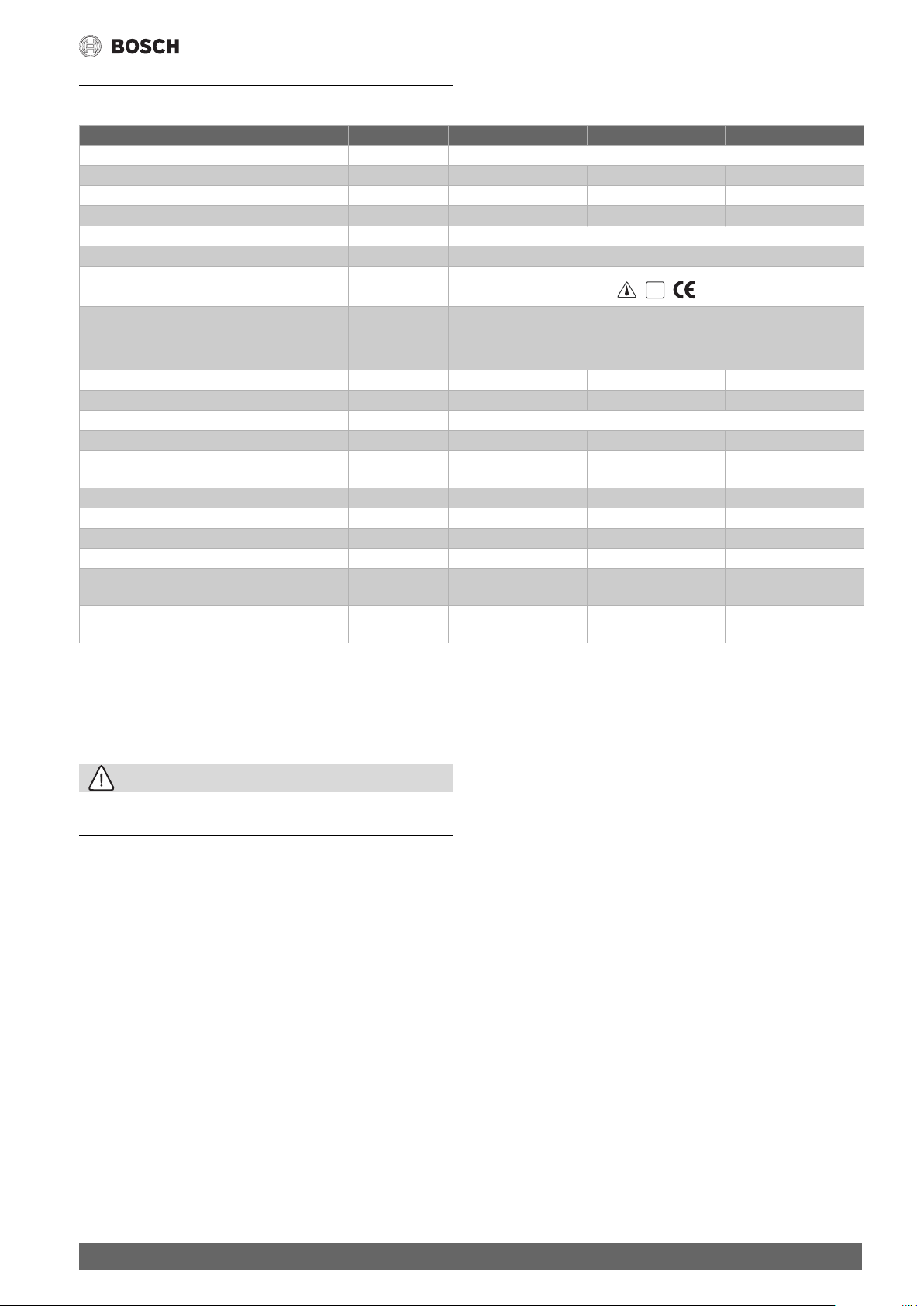
Nennspannung
Anschlussspannung 1/N/PE
230 V~
3/N/PE
400 V~
Grundheizung
8 h 2 kW 2 kW 3 kW 4 kW
4 h 4 kW 4 kW 6 kW 6 kW
Schnellheizung 4 kW 6 kW
Schaltplan (Bild 5)
Verbindliches Schaltbild im Gerät.
Änderungen vorbehalten.
Der Schalter b2 ist vom Werk auf Stellung „I“ (Aufheizdauer 8 Stunden)
voreingestellt.
b1 Taster für Schnellheizung
b2 Umschalter für Grundheizung
k1 Schaltschütz
k2 Schaltschütz
f1 Temperaturregler und
Sicherheits-Temperaturbegrenzer
r1, r2, r3 Heizkörper je 2 kW/230 V~
Weitere Anschlussmöglichkeiten (Bild 6)
1 EVU-Kontakt
Bei Betrieb ohne EVU-Steuerung Brücke zwischen L1 und 5 schalten.
Je nach Energieversorgungs-Unternehmen kann der Zeitraum für die Be-
reitstellungdes Niedrigtarif-Stromes begrenzt sein.
Die Grundheizung kann daher mit dem Umschalter b2 so geschaltet
werden, dass sich der Speicher wahlweise in 4 Stunden oder 8 Stunden
aufheizt.
Lässt das EVU keine Starkheizung zu, muss der Taster mit der im
Schaltraum liegenden Kunststoffkappe abgedeckt werden.
2-Zählermessung (Phasengleichheit beachten) (Bild 7)
1 EVU-Kontakt
k1 Schaltschütz
k2 Schaltschütz
1/N/PE – 230 V~: ohne gestrichelte Linien
3/N/PE – 400 V~: mit gestrichelten Linien
4
TR2000TF – 6 720 875 992 (2017/07)
Page 5
Technische Daten
3 Technische Daten
TR2000TF 200 T TR2000TF 300 T TR2000TF 400 T
Bauart geschlossen
Inhalt [l] 200 300 400
Nennüberdruck [MPa (bar)] 0,6 (6) 0,6 (6) 0,6 (6)
Gewicht, leer [kg] 53 68 85
Schutzklasse nach VDE I
Schutzart VDE IP 24D
Prüfzeichen
Kaltwasser-Anschluss
Warmwasser-Anschluss
Zirkulations-Anschluss
Durchflussmenge max. [l/min] 30 38 45
Nennspannung [V~] 230/400 230/400 230/400
Behälterwerkstoff Stahl, innen spezialemailliert
Energieeffizienzklasse C C C
Warmwasserbereitungs-Energieeffizi-
enz
Lastprofil XL XL XL
Jahresenergieverbrauch [kWh] 4 332 4 316 4 357
Täglicher Stromverbrauch [kWh] 19,920 19,828 20,700
Schallleistungspegel [dB] 15 15 15
Mischwassermenge V40
gemäß EU-Verordnung 814/2013
Mischwassermenge 40 °C (15 °C/65 °C)
gemäß EN60379
[%] 38,7 38,8 38,4
[l] 317 490 617
[l] 397 590 780
DIN
AGI
G 1 A
G 1 A
G 1/2 A
4 Gebrauchsanleitung
Bitte die ausführlichen Sicherheitshinweise am Anfang dieser Anleitung durchlesen und beachten!
• Wichtig: Das Gerät niemals Frost aussetzen!
VORSICHT:
Stromschlaggefahr!
▶ Schalten Sie im Fehlerfall sofort die Netzspannung ab!
• Bei einer Undichtigkeit am Gerät sofort die Kaltwasserzuleitung
schließen.
4.1 Ihr neues Gerät
Mit diesem Speicher können Sie bedarfsgerecht Trinkwasser für den
Hausgebrauch bis etwa 60 °C aufheizen und speichern.
Die maximal einstellbare Temperatur kann auf Wunsch durch einen Fachmann auf ca. 80 °C erhöht werden.
Es können mehrere Zapfstellen mit warmem Wasser versorgt werden. An
den Mischbatterien kann jederzeit Kaltwasser entnommen werden.
Unsere Produkte sind umweltfreundlich, recyclingfähig und energiesparend.
So bedienen Sie den Standspeicher (Bild 8)
• Die Bedienblende am Gerät erleichtert das Einstellen. Sie zeigt für
die verschiedenen Einstellungen Temperaturen, Wassermengen und
wie viele Wannenbäder oder Duschbäder möglich sind.
• Mit dem Temperaturwähler 1 wählen Sie die gewünschte
Temperatur vor.
4.2 Stellung
• Kalt und Frostschutz
I Das Wasser wird auf ca. 38 °C erwärmt.
E Energie-Sparstellung. Das Wasser wird auf ca. 60 °C erwärmt.
Bei Stellung „E“ spüren Sie eine Rastung.
III Einstellung für Heißwasser und großen Warmwasserbedarf.
Das Wasser wird auf ca. 80 °C erwärmt. (Einstellung durch den
Fachmann)
• Beim Aufheizen tropft Ausdehnungswasser aus dem Sicherheitsventil.
• Drehen Sie den Temperaturwähler 1 in Stellung „•“, um die Heizung
auszuschalten.
4.3 Betrieb in der Niedertarifzeit (Nachtstrom)
Dies ist die kostengünstigste Betriebsweise.
Am Temperaturwählknopf 1 stellen Sie die gewünschte Wassertempera-
tur ein.
• Das Energieversorgungs-Unternehmen gibt den Niedertarif- Strom
durch ein Signal über das elektrische Netz frei. Die Grundheizung
schaltet sich dann automatisch ein.
Tagsüber steht Ihnen das warme Wasser zur Verfügung.
4.4 Zusätzlicher Betrieb während der Haupttarifzeit
Reicht die während der Nacht bereitete Warmwassermenge nicht aus,
kann während der Haupttarifzeit das Wasser zusätzlich erwärmt werden:
• Drucktaster 2 betätigen.
Das Wasser wird auf die am Temperaturwählknopf 1 eingestellteTemperatur erwärmt. Ist die gewählte Temperatur erreicht, schaltet die Starkheizung automatisch ab.
TR2000TF – 6 720 875 992 (2017/07)
5
Page 6

Wartungsanleitung
• Stellen Sie am Temperaturwählknopf 1 eine höhere Temperatur ein,
wenn es häufiger vorkommt, dass Sie während der Haupttarifzeit
nachheizen müssen. Sie erreichen dadurch eine größere Mischwassermenge.
• Drehen Sie den Temperaturwählknopf 1 auf Stellung „•“, wenn der
Speicher längere Zeit nicht aufheizen soll. In dieser Stellung ist das
Gerät frostgeschützt.
Dies gilt nicht für Armaturen und Rohre im Kaltwasserzulauf!
4.5 Sicherheitsventil kontrollieren
Während des Aufheizens muss das Ausdehnungswasser aus dem Ablauf
3 des Sicherheitsventils sichtbar abtropfen.
Der Ablauf darf aus Sicherheitsgründen nicht abgesperrt werden.
• Prüfen Sie mindestens einmal im Monat die Funktionsfähigkeit
des Sicherheitsventils.
• Lüftungsschraube 4 drehen, bis sich Ventil öffnet und ein kräftiger
Wasserstrahl aus dem Auslauf 3 austritt.
• Ventil mit Lüftungsschraube wieder schließen.
• Funktioniert das Sicherheitsventil nicht wie beschrieben, Temperaturwähler auf Stellung „•“ drehen und einen Fachmann rufen.
4.6 Energie sparen
Bei niedrigen Temperaturen arbeitet das Gerät besonders wirtschaftlich. Stellen Sie deshalb nur die Temperatur ein, die Sie benötigen.
In der Stellung „E“ (ca. 60 °C) arbeitet der Speicher, auch bei größerem
Warmwasserbedarf, am wirtschaftlichsten. Bei höheren Wassertemperaturen verkalkt das Gerät stärker und es treten höhere Wärmeverluste auf!
4.7 Entkalken
• Die Armaturen regelmäßig auf Kalkablagerungen überprüfen und Ablagerungen mit handelsüblichen Entkalkungsmitteln entfernen.
• Das Sicherheitsventil regelmäßig betätigen, um Kalk zu entfernen
(siehe „Sicherheitsventil kontrollieren“).
In Abhängigkeit von der örtlichen Wasserqualität (Härtebereich I/II/III;
weich, mittel oder hart) wird bei hohen Temperaturen mehr oder weniger Kalk aus dem Wasser ausgeschieden.
Dieser setzt sich im Inneren des Speichers und auf dem Heizflansch als
Kesselstein ab und beeinflusst die Lebensdauer des Gerätes. Das Gerät
muss daher regelmäßig von einem Fachmann überprüft und entkalkt
werden.
Bitte stimmen Sie mit Ihrem Fachmann den ersten bzw. den nächsten
Wartungstermin (Kontrolle Schutzanode und Entkalkung) ab.
Wartungsarbeiten dürfen nur von einem Fachmann durchgeführt
werden. Durch unsachgemäße Reparaturen können erhebliche Gefah-
ren für den Benutzer entstehen.
4.8 Reinigung
• Das Gerät nur feucht abwischen. Verwenden Sie keine scharfen oder
scheuernden Reinigungsmittel.
4.9 Kundendienst
• Trennen Sie bei einer Störung das Gerät vom elektrischen Netz
(Sicherungen herausdrehen oder Sicherungsautomat auslösen)
und verständigen den Kundendienst.
Die nächstgelegene Kundendienststelle oder Vertragswerkstatt kann bei
einem Kundendienst-Zentrum erfragt werden.
• Wenn Sie den Kundendienst anfordern, geben Sie bitte die BOSCHSeriennummer (SNR/TTNR) Ihres Gerätes an.
5 Wartungsanleitung
VORSICHT:
▶ Wartungsarbeiten müssen von einem Fachmann unter Beach-
tung von VDE 0700 oder der örtlichen Vorschriften durchgeführt
werden.
• Das Gerät muss allpolig vom elektrischen Netz getrennt werden.
5.1 Entkalken
Verwenden Sie keine Entkalkungspumpe. Damit würde zwar der Heizflansch entkalkt, jedoch die Schutzanode und die Behälterinnenwand
zerstört werden.
Vorgehensweise:
• Standspeicher vom elektrischen Netz trennen.
• Schaltraumkappe abnehmen.
• Heizflansch abklemmen und ausbauen.
• Heizflansch entkalken.
• Lose Kalkteile aus dem Speicher entfernen.
• Heizflansch montieren und gemäß Schaltplan anschließen.
• Schaltraumkappe montieren.
5.2 Schutzanode überprüfen
Zum Überprüfen muss die Schutzanode ausgebaut werden.
Sie befindet sich neben dem Warmwasserauslauf, abgedeckt durch die
Wärmedämmung (erkennbar durch eine deutliche Erhöhung).
• Schutzhülle mit dem Reißverschluss öffnen. Wärmedämmung mit einem Messer ausschneiden.
• Schutzanode ausschrauben und prüfen.
Ist die Schutzanode verbraucht, muss sie durch eine neue ersetzt werden.
Ist der Einbau einer Stabanode aus Platzgründen nicht möglich, installie-
ren Sie eine Ketten-Schutzanode.
Sie muss guten metallisch leitenden Kontakt mit dem Speicher haben.
Anodenverschraubung mit herausgeschnittenem Wärmedämm-Material
oder einer entsprechenden Wärmedämmung abdecken.
• Schutzhülle verschließen.
Hinweis: Die im Speicher eingebaute Schutzanode muss erstmalig nach
zwei Jahren überprüft und falls erforderlich ausgetauscht werden.
Der Fachmann kennt die örtliche Wasserqualität und wird den Zeitpunkt
für die nächste Wartung nennen.
5.2.1 Sicherheitsventil
• Das Sicherheitsventil anlüften, bis der volle Wasserstrahl ausläuft.
• Nach der Kontrolle Sicherheitsventil schließen.
Sicherheitseinrichtung (Bild 9)
5 Sicherheits-Temperaturbegrenzer
6 Korrosionsschutz-Widerstand
7 Heizflansch
8 Rückstelltaste
Temperaturregler und Sicherheits-Temperaturbegrenzer sind zusammen im Heizflansch eingebaut. Schaltet der Sicherheits- Temperaturbegrenzer bei einer Störung das Gerät ab, so muss grundsätzlich die
komplette Einheit ausgetauscht werden. Die Fehlerursache muss von einem Fachmann beseitigt werden.
Der Heizflansch ist über den Korrosionsschutz-Widerstand mit dem Behälter verbunden. Der Korrosionsschutz-Widerstand dient als Potenzialabgleich und verhindert Stromaustrittskorrosion an den Heizkörpern.
Der Widerstand darf bei Servicearbeiten nicht beschädigt oder entfernt
werden (Einbaulage siehe Abbildung).
6
TR2000TF – 6 720 875 992 (2017/07)
Page 7

5.3 Entsorgung
Dieses Gerät ist entsprechend der europäischen Richtlinie
2012/19/EU über Elektro- und Elektronikaltgeräte
(waste electrical and electronic equipment – WEEE) gekennzeichnet.
Die Richtlinie gibt den Rahmen für eine EU-weit gültige Rücknahme und Verwertung der Altgeräte vor.
Über aktuelle Entsorgungswege bitte beim Fachhändler informieren.
Wartungsanleitung
TR2000TF – 6 720 875 992 (2017/07)
Änderungen vorbehalten.
7
Page 8

Table of Contents
Table of Contents 1 Safety information
1 Safety information. . . . . . . . . . . . . . . . . . . . . . . . . . . . . . . . . . . . 8
2 Installation instructions . . . . . . . . . . . . . . . . . . . . . . . . . . . . . . . 9
2.1 Installation . . . . . . . . . . . . . . . . . . . . . . . . . . . . . . . . . . . . 9
2.1.1 Description of the appliance . . . . . . . . . . . . . . . . . . . . . . 9
3 Technical data. . . . . . . . . . . . . . . . . . . . . . . . . . . . . . . . . . . . . . . 11
4 Operating instructions . . . . . . . . . . . . . . . . . . . . . . . . . . . . . . . 11
4.1 Your new appliance . . . . . . . . . . . . . . . . . . . . . . . . . . . . 11
4.2 Position. . . . . . . . . . . . . . . . . . . . . . . . . . . . . . . . . . . . . . 11
4.3 Operation during the off-peak period
(off‑peak power) . . . . . . . . . . . . . . . . . . . . . . . . . . . . . . 11
4.4 Additional operation during the peak period . . . . . . . . 11
4.5 Checking the safety valve. . . . . . . . . . . . . . . . . . . . . . . . 12
4.6 Saving energy . . . . . . . . . . . . . . . . . . . . . . . . . . . . . . . . . 12
4.7 Decalcifying . . . . . . . . . . . . . . . . . . . . . . . . . . . . . . . . . . 12
4.8 Cleaning . . . . . . . . . . . . . . . . . . . . . . . . . . . . . . . . . . . . . 12
4.9 Customer Service. . . . . . . . . . . . . . . . . . . . . . . . . . . . . . 12
5 Maintenance instructions . . . . . . . . . . . . . . . . . . . . . . . . . . . . . 12
5.1 Decalcifying . . . . . . . . . . . . . . . . . . . . . . . . . . . . . . . . . . 12
5.2 Checking the protective anode . . . . . . . . . . . . . . . . . . . 12
5.2.1 Safety valve. . . . . . . . . . . . . . . . . . . . . . . . . . . . . . . . . . . 12
5.3 Disposal . . . . . . . . . . . . . . . . . . . . . . . . . . . . . . . . . . . . . 13
6 Guarantee . . . . . . . . . . . . . . . . . . . . . . . . . . . . . . . . . . . . . . . . . .13
This appliance is intended for domestic use or for household-based,
non-commercial applications. Household-based applications include,
e.g. usage in employees catering facilities for shops, offices, agricultural
and other commercial operations, as well as usage by guests of guest
houses, small hotels and similar residential establishments.
• Install and operate the appliance as described in the text and illustrations. We do not accept liability for damage resulting from failure to
heed these instructions.
• This appliance is intended for use up to a maximum altitude of
2 000 m above sea level.
• The appliance may only be installed and stored in a frost-free room
(due to residual water).
CAUTION:
Risk of electric shock!
▶ Switch off the mains voltage supply immediately if a fault occurs.
▶ Immediately shut off the cold water supply to the appliance
should it leak.
• Installation and initial start-up may only be carried out by a qualified
professional in accordance with these instructions!
• Maintenance work must be carried out by a qualified professional
pursuant to recognised national regulations required by law
(e. g. IEC 60 364‑7‑701).
• Apart from the recognised national regulations required by law
(e. g. IEC 60 364‑7‑701, DIN 1988), connection conditions issued
by the power supply and water companies must be observed.
• The (Class I) appliance must be permanently connected to installed
pipes. The conductor cross-section must comply with the
installed appliance power.
• Caution: Earthed water pipes may give the appearance of
a connected protective earth.
• To guarantee compliance to relevant safety regulations, an all-pole
separator must be fitted during installation. The contact opening
must be at least 3 mm.
• Disconnect the electrical connection cable from the supply and
shut off the water supply before connecting the appliance!
• The floor-standing water heater must be secured to the ground!
• During the heating process, expansion water must drip out of the
safety valve outlet.
• Supplied stickers: “For reasons of safety, water must come out of the
outlet pipe during the heating period! Do not block!” – attach the
stickers to the outlet pipe in a clearly visible position.
The safety valve prevents excessive pressure from developing in thefloor-standing water heater during the heating process. Expansion water
must be able to drain off via the safety valve.
Do not block the outlet pipe!
• The size of the outlet pipe must suit the fully opened safety valve. The
blow-off opening of the safety valve must remain open to the atmosphere.
• The blow-off pipe of the safety group must be installed with a constant decline in a frost-free environment. Regular maintenance and
operation of the safety valve are required to remove deposits and to
ensure that the safety valve is not blocked.
• The installation instructions of the safety group must be followed.
• Only a prototype-tested diaphragm safety valve may be installed.
• A shutoff valve must not be installed between the safety valve and
floor-standing water heater.
• The safety valve must be operated regularly to verify its function and
to descale the valve.
8
TR2000TF – 6 720 875 992 (2017/07)
Page 9

Installation instructions
• This appliance can be used by children aged 8 years and older as well
as by persons with diminished bodily, sensory or mental perception,
or those who lack knowledge or experience, if they are monitored
or have received instruction concerning use and comprehend the
possible dangers that can result. Children may not play with the
appliance. Cleaning and maintenance by the user may not be
performed by unsupervised children.
• Keep children away from the appliance.
• Please monitor children to ensure that they do not play with the
appliance.
• The mixer and the warm water pipe may be hot. Please inform and instruct children appropriately.
• Do not use aggressive or abrasive cleaning detergents!
• Do not use a steam cleaner.
CAUTION:
DANGER Scalding!
▶ Hot water may escape during draining.
If the appliance needs to be drained for maintenance or to protect the
whole installation when there is a risk of frost, proceed as follows:
• Close the shut-off valve in the cold water line.
• Open the hot water taps on all draw-off points.
• Drain the appliance using the drain valve.
Congratulations on purchasing this appliance. You have acquired a topquality product, which will give you a lot of enjoyment.
Please read this installation and operating instruction manual
carefully, then act accordingly! Store for future reference.
2 Installation instructions
Install the floor-standing water heater as described in the illustrated
section. Observe the instructions in the text.
The illustrations can be found at the end of the instruction manual.
2.1 Installation
For economic reasons the installation location should be near the most
frequently used tap connection.
2.1.1 Description of the appliance
The interior of the steel tank has been specially enamelled to prevent
corrosion and has been fitted with a protective anode. The exterior has
been directly insulated with foam which cannot be removed. Cover the
appliance with the supplied protective jacket only when the installation
work is complete.
The universal flange enables electrical connections for single or double
circuit operation. Circulation pipes should be avoided on account of the
high heat losses. The circulation connection is located where the thermal
insulation is noticeably indented.
Parts supplied (Fig. 1 )
1 Floor-standing water heater
2 Protective jacket
Appliance design (Fig. 2 )
3 Hot-water outlet
4 Protective anode
5 Circulation connection piece
6 Mark for circulation connection piece
7 Steel tank, enamelled interior
8 Thermal insulation
9 Temperature selector switch
10 Push-button
11 Heating flange
12 Cold-water inlet
Dimensions (Fig. 3 )
Water connection (Fig. 4 )
• Comply with DIN 1988 and the regulations issued by the water
company.
Materials for cold-water and hot-water pipes
Water pipe made of steel, copper or plastic.
If plastic pipes are used, only install pipe systems made of crosslinked
polyethylene (high-density polyethylene) according to DIN 16893 series
2 (20 bar), checked in accordance with DVGW work sheets W 531 and
W 532 with the corresponding DVGW mark of conformity.
Information regarding the suitability and quality of other plastic pipes
without the above-mentioned design approval information can only be
provided by the pipe manufacturer.
Copper pipes are recommended if there is a risk of corrosion.
If using copper and steel materials, they must be joined in the following
sequence, as seen from the flow of direction: Copper comes after steel.
This will avoid corrosion by local cell formation.
Stipulated combinations:
• Cold-water pipe made of copper: hot-water pipe made of copper or
plastic
• Cold-water pipe made of steel: hot-water pipe made of steel, copper
or plastic
• Cold-water pipe made of plastic: hot-water pipe made of steel,
copper or plastic
Pressure reducing valve
The floor-standing water heater is designed to operate at pressures not
exceeding 0,6 MPa (6 bar). A pressure reducing valve must be situated
in the cold-water pipe if the water mains pressure exceeds 0,5 MPa (5
bar). If the water mains pressure exceeds 1,0 MPa (10 bar), a second
pressure reducing valve must be connected in series.
Installation example (Fig. 4 )
1 Thermostat
2 Time switch
3 Circulation pump
4 Non-return valve
5 Outlet valve
6 Safety valve
7 Through-way shutoff valve
8 Test connection piece for manometer
9 Test valve
10 Pressure reducing valve
(only when water supply pressure exceeds 0,5 MPa (5 bar))
11 Cold-water inlet
The fittings and safety devices indicated in the diagram must be used for
the installation and they must be fitted in the sequence shown
(see DIN 1988 or local regulations).
For easier installation we recommend the use of our compact safety
valve units.
If a central battery (thermostat battery) is used, a device must be fitted
directly to the hot-water outlet of the floor-standing water heater,
in order to measure the cut-out temperature.
Electrical connection (Fig. 5 )
• Electrical installation must only be carried out by an electrician from
the power supply company.
TR2000TF – 6 720 875 992 (2017/07)
9
Page 10

Installation instructions
• The power supply must only be connected after the water supply.
Connections must be carried out according to the circuit and terminal
diagrams. The ratings permitted by the power supply company for
primary/rapid heating, as well as the heating duration, must be
observed. The internal circuitry must not be altered. The rating plate,
norms, regulations and guidelines must be observed.
• Floor-standing water heaters have special connections on the
terminal strip for control cables and contactors.
• The protective conductor terminal is indentified by the protective
conductor sign.
• An all-pole disconnecting device with a min. 3 mm gap construction
must be fitted by the installation company.
CAUTION:
Attention!
▶ The appliance must not be connected by a two-pole-and-
earthing-pin plug.
Connection work
• Remove switchroom cap.
• Push power cable and control lead through the cable inlet and
connect in accordance with the circuit diagram.
• Connect the protective conductor to the protective conductor
terminal.
• Tighten the screwed connections of the cable inlets.
• Place the rating stickers in the position marked on the rating plate.
• Fit the switchroom cap.
Rated voltage
Supply-voltage 1/N/PE
230 V~
3/N/PE
400 V~
Primary heating
8 h 2 kW 2 kW 3 kW 4 kW
4 h 4 kW 4 kW 6 kW 6 kW
Rapid heating 4 kW 6 kW
Circuit diagram (Fig. 5 )
Mandatory circuit diagram inside the appliance.
Subject to change without notice.
Switch b2 has been preset at the factory to position „I“ (heating duration
8 hours).
b1 Push-button for rapid heating
b2 Selector switch for primary heating
k1 Contactor
k2 Contactor
f1 Thermostat and thermal cut-out
r1, r2, r3 Heaters, each 2 kW/230 V~
Other connection options (Fig. 6)
1 Power supply company contact
When operating without a controller from the power supply company,
place a bridge between L1 and 5.
Depending on the power supply company, the period in which off-peak
power is supplied may be restricted.
Primary heating can therefore be set with selector switch b2, so that the
floor-standing water heater heats up in either 4 or 8 hours.
If the power supply company does not permit peak-rate heating, the
push-button must be covered with the plastic cap situated in the
switchroom.
2-Dual meter measurement (comply with phase coincidence) (Fig. 7)
1 Power supply company contact
k1 Contactor
k2 Contactor
1/N/PE – 230 V~: without broken lines
3/N/PE – 400 V~: with broken lines
10
TR2000TF – 6 720 875 992 (2017/07)
Page 11

Technical data
3 Technical data
TR2000TF 200 T TR2000TF 300 T TR2000TF 400 T
Design sealed (pressurised)
Capacity [l] 200 300 400
Rated pressure [MPa (bar)] 0.6 (6) 0.6 (6) 0.6 (6)
Weight empty [kg] 53 68 85
Class of protection accord. to VDE I
Degree of protection accord. to VDE IP 24D
Mark of conformity
Cold-water connection
Hot-water connection
Circulation connection
Flow rate max. [l/min] 30 38 45
Rated voltage [V~] 230/400 230/400 230/400
Tank material steel. interior specially enamelled
Energy efficiency class C C C
Hot water heating energy efficiency [%] 38.7 38.8 38.4
Load profile XL XL XL
Annual energy consumption [kWh] 4 332 4 316 4357
Daily energy consumption [kWh] 19.920 19.828 20.700
Sound power level [dB] 15 15 15
Mixed water quantities V40 according to
the European Guideline 814/2013
Mixed water quantities at 40 °C (15 °C/65
°C) according to EN60379
[l] 317 490 617
[l] 397 590 780
DIN
AGI
G 1 A
G 1 A
G 1/2 A
4 Operating instructions
Please read and observe the detailed safety instructions at the start
of these instructions!
• Important: The appliance may never be exposed to frost!
CAUTION:
Risk of electric shock!
▶ Switch off the mains voltage supply immediately if a fault occurs.
• Immediately shut off the cold water supply to the appliance should it
leak.
4.1 Your new appliance
This floor-standing water heater enables you to heat up as much drinking
water as required to approximately 60 °C and store it for household use.
On request a qualified professional will increase the maximum
adjustable temperature to approx. 80 °C.
Several tap connections can be supplied with hot-water. The mixers can
always supply cold-water.
Our products are environment-friendly, can be recycled and conserve
energy.
How to operate the floor-standing water heater (Fig. 8)
• Adjustments are facilitated by the control panel on the appliance. The
control panel indicates the various settings, temperatures, volumes
of water and how many baths or showers may be taken.
• Preselect the required temperature with temperature selector
switch 1.
4.2 Position
• Cold and anti-freezing protection
I The water is heated to approx. 38 °C.
E Energy conservation position. The water is heated to approx.
60 °C.
The selector switch will click into place at position “E”.
III Setting for hot-water and when large amounts of hotwater are
required. The water is heated to approx. 80 °C. (this setting only by
qualified professional)
• During the heating process, expansion water drips out of the safety
valve.
• Rotate the temperature selector switch 1 to position “•” to switch off
the heating.
4.3 Operation during the off-peak period
(off‑peak power)
This is the most cost-effective mode of operation.
Set the required water temperature with the temperature selector
switch 1.
• The power supply company activates off-peak power by means of
a signal in the power system. Primary heating then switches on
automatically.
You will then have hot-water during the day.
4.4 Additional operation during the peak period
If the volume of hot-water provided during the night is insufficient, water
can also be heated during the peak period:
• Press push-button 2.
The water is heated to the temperature set on the temperature selector
switch 1. When the selected temperature has been reached, the peakrate heating automatically switches off.
TR2000TF – 6 720 875 992 (2017/07)
11
Page 12

Maintenance instructions
• Set a higher temperature with the temperature selector switch 1 if
you frequently need to reheat water during the peak period.
As a result, you will have a larger volume of mixed water.
• Rotate the temperature selector switch 1 to position “•” if the floor-
standing water heater will not be heated for a prolonged period.
This setting protects the appliance from freezing.
This does not apply to the fittings and pipes in the cold-water inlet!
4.5 Checking the safety valve
During the heating process, expansion water must drip out of the safety
valve outlet 3.
For reasons of safety the outlet must not be blocked.
• Check that the safety valve is functioning properly at least once
a month.
• Rotate ventilation screw 4 until the valve opens and a powerful jet of
water comes out of the outlet 3.
• Close the valve again with the ventilation screw.
• If the safety valve does not function as described, rotate the
temperature selector switch to position “•” and contact a qualified
professional.
4.6 Saving energy
The appliance operates particularly economically at low temperatures.
Therefore, only set the temperature which you require.
The floor-standing water heater operates most economically in position
“E” (approx. 60 °C), even when large amounts of hot-water are required.
At higher water temperatures, the appliance calcifies at an increased
rate, resulting in greater heat losses!
4.7 Decalcifying
• Inspect the fittings regularly for lime scale deposits and descale with
commercially available descaling agents.
• Actuate the safety valve regularly to remove the lime scale (see
“Checking the safety valve”).
The level of lime scale deposited from the water is increased or reduced
at higher temperatures depending on the local water quality (hardness
level I/II/III; soft, medium or hard). It is deposited on the interior of the
water tank and on the heating element as boiler scale and influences the
service life of the appliance.
The appliance must therefore be checked and decalcified regularly by
a qualified professional.
Please schedule your first and/or next maintenance visit (inspection of
the protection anode and descaling) with your qualified specialist.
Maintenance work may only be carried out by a qualified
professional. Improper repairs may put the user in extreme danger.
4.8 Cleaning
• Simply wipe the appliance with a damp cloth. Do not use acidic or
abrasive cleaning materials.
4.9 Customer Service
• In the event of a malfunction, unplug the appliance from the power
supply (pull out the fuse or activate the circuit breaker) and contact
customer service.
Details can be obtained from a customer service centre regarding your
nearest customer service centre or authorised repair shop.
• We ask you to always provide the BOSCH serial number (SNR/TTNR)
of your appliance when calling in a customer service engineer.
5 Maintenance instructions
CAUTION:
▶ Maintenance work must only be carried out by a qualified
professional, pursuant to VD E0700 or local regulations.
• The appliance must be isolated from the power supply in all poles.
5.1 Decalcifying
Do not use a decalcifying pump. This would decalcify the heating flange
but would damage the protective anode and the interior wall of the tank.
Procedure:
• Disconnect the floor-standing water heater from the power supply.
• Remove the switchroom cap.
• Disconnect the heating flange and remove.
• Decalcify the heating flange.
• Remove loose pieces of lime from the floor-standing water heater.
• Fit the heating flange and connect in accordance with the circuit
diagram.
• Fit the switchroom cap.
5.2 Checking the protective anode
The protective anode must be removed prior to checking.
It is situated next to the hot-water outlet nozzle and is covered by the
thermal insulation (recognizable by a protrusion).
• Unzip the protective jacket. Cut out the thermal insulation with
a knife.
• Screw out the protective anode and check.
If the protective anode is used up, it must be replaced with a new one.
If there is insufficient space to install a pole anode, install a chain anode.
The protective anode must have a good metallic conduction with the
floor-standing water heater. Cover the screwed connection of the anode
with the piece of thermal insulation material which was previously cut
out.
• Zip up the protective jacket.
Note: The protective anode, located in the floor-standing water heater,
must be checked for the first time after two years and replaced if
necessary. The qualified professional is familiar with the local water
quality and will specify when the next maintenance check should be
carried out.
5.2.1 Safety valve
• Vent the safety valve until the full water jet is flowing out.
• Close the safety valve after carrying out the check.
Safety equipment (Fig. 9)
5 Thermal cut-out
6 Corrosion protection anode resistor
7 Heating flange
8 Reset button
The thermostat and thermal cut-out are located together in the heating
flange. If the thermal cutout disconnects the appliance due to
a malfunction, the whole unit must always be replaced. The cause of the
malfunction must be eliminated by a qualified professional.
The heating flange is connected with the tank via the corrosion protection
anode resistor. The corrosion protection anode resistor serves to equalise
electrical potential differences and prevents current-related corrosion to
the heating elements. The anode resistor is not to be damaged or removed
during servicing (for mounting position, refer to figure).
12
TR2000TF – 6 720 875 992 (2017/07)
Page 13

Guarantee
5.3 Disposal
This appliance is labelled in accordance with European
Directive 2012/19/EU concerning used electrical and
electronic appliances (waste electrical and electronic
equipment – WEEE).
The guideline determines the framework for the return and
recycling of used appliances as applicable throughout the EU.
Please ask your specialist retailer about current disposal
facilities.
6 Guarantee
The guarantee conditions for this appliance are as defined by our
representative in the country in which it is sold.
Details regarding these conditions can be obtained from the dealer from
whom the appliance was purchased. The bill of sale or receipt must be
produced when making any claim under the terms of this guarantee.
TR2000TF – 6 720 875 992 (2017/07)
Subject to change without notice.
13
Page 14

2
G1 A
1
G1 A
G1/2 A
1
3
4
5
6
7
8
9
10
11
12
3
TR2000TF 200 T TR2000TF 300 T TR2000TF 400 T
Ø a [mm] 550 650 700
b [mm] 690 790 840
c [mm] 340 365 375
Ø e [mm] 430 490 540
l [mm] 75 75 75
k [mm] 1035 1040 1160
h ± 10 [mm] 1545 1560 1730
1
2
Page 15

4
6
R
1
2
3
4
784 10 7
5911
5
Page 16

6
7
Page 17

8
9
Page 18

Guarantee
18
TR2000TF – 6 720 875 992 (2017/07)
Page 19

Guarantee
TR2000TF – 6 720 875 992 (2017/07)
19
Page 20

6720875992
Bosch Thermotechnik GmbH
Junkersstrasse 20-24
D-73249 Wernau
www.bosch-thermotechnology.com
 Loading...