

Bosch TR2000 18 B, TR2000 24 B, TR2000 12 B, TR2000R 21B, TR2000R 18B Installation And Operating Instructions Manual
...
Montage- und Gebrauchsanleitung
Installation and operating instructions
Notice de montage et d’utilisation
Montage- en gebruikshandleiding
Instrukcja montażu i użytkowania
Návod pro montáž a návod k použití
Инструкция по монтажу и эксплуатации
Uputstvo za montažu i upotrebu
Upute za montažu i uporabu
TR2000 | TR2000R
TR2000 12 | 18 | 21 | 24 B
TR2000R 18 | 21 | 24 B
Instrucciones de instalación y de uso
Manual de instalação e serviço
คำอธิบายชี้แจงในการประกอบ ติดตั้งและคำชี้แจง วิธี ใช้
ᆹ㻵઼֯⭘䈤᰾Җ
Namestitev in uporaba
Инсталација и упатство за употреба
Montimi dhe udhëzimet e përdorimit
Инструкции за монтаж и експлоатация
6 720 876 014 (2018/04)DIV
Inhaltsverzeichnis
Inhaltsverzeichnis 1 Sicherheitshinweise
1 Sicherheitshinweise . . . . . . . . . . . . . . . . . . . . . . . . . . . . . . . . . . 2
2 Montageanleitung . . . . . . . . . . . . . . . . . . . . . . . . . . . . . . . . . . . . 3
2.1 Montage . . . . . . . . . . . . . . . . . . . . . . . . . . . . . . . . . . . . . . 3
3 Technische Daten. . . . . . . . . . . . . . . . . . . . . . . . . . . . . . . . . . . . . 4
4 Sonderzubehör . . . . . . . . . . . . . . . . . . . . . . . . . . . . . . . . . . . . . . . 4
5 Gebrauchsanleitung . . . . . . . . . . . . . . . . . . . . . . . . . . . . . . . . . . 4
5.1 Gerät kennenlernen . . . . . . . . . . . . . . . . . . . . . . . . . . . . . 5
5.2 Gerät bedienen. . . . . . . . . . . . . . . . . . . . . . . . . . . . . . . . . 5
5.2.1 Inbetriebnahme nach Wasserabschaltung . . . . . . . . . . . 5
5.2.2 Energie sparen . . . . . . . . . . . . . . . . . . . . . . . . . . . . . . . . . 5
5.2.3 Winterbetrieb . . . . . . . . . . . . . . . . . . . . . . . . . . . . . . . . . . 5
6 Reinigung . . . . . . . . . . . . . . . . . . . . . . . . . . . . . . . . . . . . . . . . . . . 5
7 Eine Störung, was tun? . . . . . . . . . . . . . . . . . . . . . . . . . . . . . . . . 6
8 Kundendienst . . . . . . . . . . . . . . . . . . . . . . . . . . . . . . . . . . . . . . . . 6
9 Entsorgung . . . . . . . . . . . . . . . . . . . . . . . . . . . . . . . . . . . . . . . . . . 6
Dieses Gerät ist nur für den privaten Haushalt und das häusliche Umfeld
bestimmt.
• Das Gerät wie in Text und Bild beschrieben montieren und bedienen.
Wir übernehmen keine Haftung für Schäden, die durch Nichtbeachtung dieser Anleitung entstehen.
• Dieses Gerät ist für den Gebrauch bis zu einer Höhe von 2 000 m
über dem Meeresspiegel bestimmt.
• Das Gerät nur in einem frostfreien Raum installieren und lagern (Restwasser).
WARNUNG:
Stromschlaggefahr!
Schalten Sie im Fehlerfall sofort die Netzspannung ab.
Bei einer Undichtigkeit am Gerät sofort die Kaltwasser zuleitung schließen.
• Der Durchlauferhitzer darf nur von einem Fachmann angeschlos-
sen und in Betrieb genommen werden.
• Um Gefährdungen zu vermeiden, dürfen Reparaturen und Wartung nur von einem Fachmann durchgeführt werden.
• Öffnen Sie niemals das Gerät, ohne die Stromzufuhr zum Gerät
unterbrochen zu haben.
• Die gesetzlichen Vorschriften des jeweiligen Landes, des örtlichen
Elektrizitäts-Versorgungsunternehmens und des Wasserwerkes müssen eingehalten werden.
• Der Durchlauferhitzer ist ein Gerät der Schutzklasse I und muss an
den Schutzleiter angeschlossen werden.
• Das Gerät muss dauerhaft an festverlegte Leitungen angeschlossen
werden. Der Leitungsquerschnitt muss der zu installierenden
Leistung entsprechen.
VORSICHT:
Geerdete Wasserleitungen können das Vorhandensein eines Schutzleiters vortäuschen.
• Zur Erfüllung der einschlägigen Sicherheitsvorschriften muss installationsseitig eine allpolige Trennvorrichtung vorhanden sein. Die
Kontaktöffnung muss mindestens 3 mm betragen.
• Der Durchlauferhitzer ist nur für den geschlossenen (druckfesten)
Betrieb geeignet.
• Armaturen müssen für den Betrieb mit geschlossenen (druckfesten)
Durchlauf erhitzern zugelassen sein.
• Den Durchlauferhitzer nur an eine Kalt wasserleitung anschließen.
• Der Durchlauferhitzer ist für den Anschluss an DVGW-geprüfte Kunststoffrohre geeignet.
• Das elektrische Anschlusskabel vor der Montage spannungslos
machen und die Wasserzuleitung absperren!
• Den Elektroanschluss erst nach dem Wasseranschluss durchführen.
• In der Rückwand nur die Öffnungen herstellen, die für die Montage
benötigt werden. Bei erneuter Montage müssen die unbenutzten Öffnungen wasserdicht verschlossen werden.
• Spannungsführende Teile dürfen nach der Montage nicht mehr berührbar sein.
• Bei Arbeiten am Wassernetz das Gerät vom elektrischen Netz trennen. Nach Abschluss der Arbeiten wie bei der ersten Inbetriebnahme
vorgehen.
• Am Gerät dürfen keine Veränderungen vorgenommen werden.
• Das Gerät darf nur zur Erwärmung von Trinkwasser im Hausgebrauch
verwendet werden.
2
TR2000 | TR2000R – 6 720 876 014 (2018/04)
Montageanleitung
• Dieses Gerät kann von Kindern ab 8 Jahren und darüber sowie von
Personen mit verringerten physischen, sensorischen oder mentalen
Fähigkeiten oder Mangel an Erfahrung und Wissen benutzt werden,
wenn sie beaufsichtigt oder bezüglich des sicheren Gebrauchs des
Gerätes unterwiesen wurden und die daraus resultierenden Gefahren verstehen. Kinder dürfen nicht mit dem Gerät spielen. Reinigung
und Benutzer-Wartung dürfen nicht von Kindern ohne Beaufsichti-
gung durchgeführt werden.
• Kinder vom Gerät fern halten.
• Kinder beaufsichtigen, um zu verhindern, dass sie mit dem Gerät
spielen.
• Die Mischbatterie und das Warmwasserrohr können heiß werden.
Kinder darauf hinweisen.
• Keine Scheuermittel oder anlösende Reinigungsmittel verwenden.
• Keinen Dampfreiniger benutzen.
• Das Entkalken des Gerätes darf nur durch einen Fachmann erfolgen.
Herzlichen Glückwunsch zum Kauf dieses Geräts aus unserem Hause
BOSCH. Sie haben ein hochwertiges Produkt erworben, das Ihnen viel
Freude bereiten wird.
Die Montage- und Gebrauchsanleitung bitte sorgfältig durchlesen,
danach handeln und aufbewahren!
Installationshinweis
• Die Installation nicht-steckerfertiger Geräte ist vom jeweiligen Netzbetreiber oder von einem eingetragenen Fachbetrieb vorzunehmen,
der Ihnen auch bei der Einholung der Zustimmung des jeweiligen
Netzbetreibers fur die Installation des Gerätes behilflich ist.
Inbetriebnahme(Bild 6/7)
Das Gerät stimmt mit IEC 61000-3-12 überein.
• Prüfen Sie, ob bei niedrigem Wasserleitungsdruck die Stufe II selbst
beim gleichzeitigen Zapfen an mehreren Kaltwasserhähnen einschaltet. Wenn nicht, entfernen Sie den Durchflussbegrenzer (siehe
Zusatzinformation A).
• Erklären Sie dem Benutzer die Bedienung des Durchlauferhitzers.
Zusatzinformationen (Bild 6, A/B)
• Schaltet der Durchlauferhitzer aufgrund von zu geringem Wasserdruck in Ihrer Hausinstallation nicht auf volle Leistung, entfernen Sie
den Durchflussbegrenzer (A 3.).
• Vorrangschaltung für die Kombination mit Elektro-Speicherheizgeräten ( B).
2 Montageanleitung
Montieren Sie den Durchlauferhitzer, wie im Bildteil beschrieben.
Beachten Sie die Hinweise im Text.
2.1 Montage
Auspacken/Haube abnehmen (Bild 1)
• Gerät auspacken und auf Transportschäden kontrollieren.
• Verpackung und gegebenenfalls Altgerät umweltgerecht entsorgen.
Montagevorbereitung (Bild 2)
Wichtig: Nur den beiliegenden Montagesatz verwenden.
• Wasserzuleitung absperren. Der elektrische Anschluss (Anschlusskabel) muss spannungsfrei sein. Sicherungen herausdrehen oder
ausschalten.
Wandmontage (Bild 3)
• Der Durchlauferhitzer muss fest an der Wand montiert werden. Befestigen Sie ihn gegebenenfalls an den unteren Stellschrauben.
• Der Wandabstand ist variabel. So können Unebenheiten der Wand
ausgeglichen werden.
• Die Tülle muss das Anschlusskabel eng umschließen.
Wird sie bei der Montage beschädigt, müssen die Löcher wasserdicht
verschlossen werden.
Wasseranschluss (Bild 4)
• Der Durchlauferhitzer muss entlüftet werden. Dazu Warmwasserhahn ganz öffnen und das Gerät 1 Minute durchspülen.
• Unbedingt den Durchflussmengenbegrenzer im Kalt wasserzulauf
einbauen.
Elektroanschluss (Bild 5)
• Die Netzanschlussklemme kann oben oder unten montiert werden.
Die Ummantelung des Anschlusskabels muss mindestens 40 mm in
das Gerät hineinragen.
TR2000 | TR2000R – 6 720 876 014 (2018/04)
3
Technische Daten
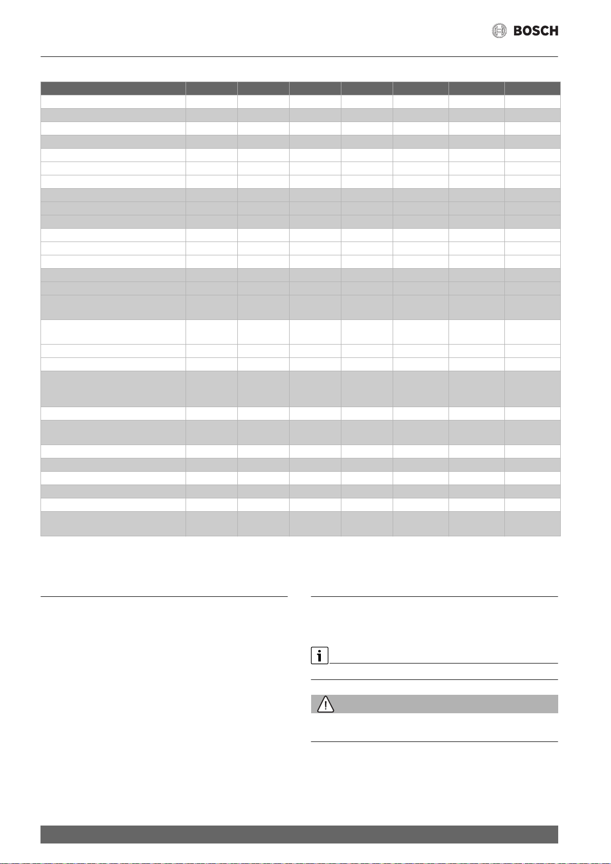
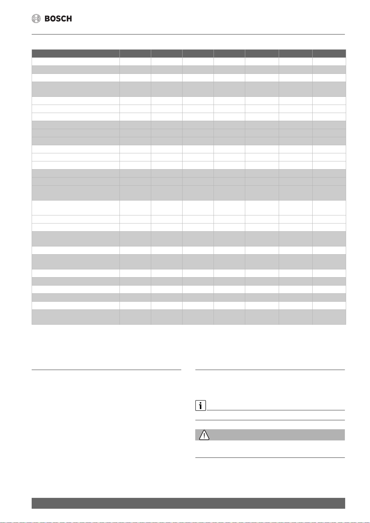
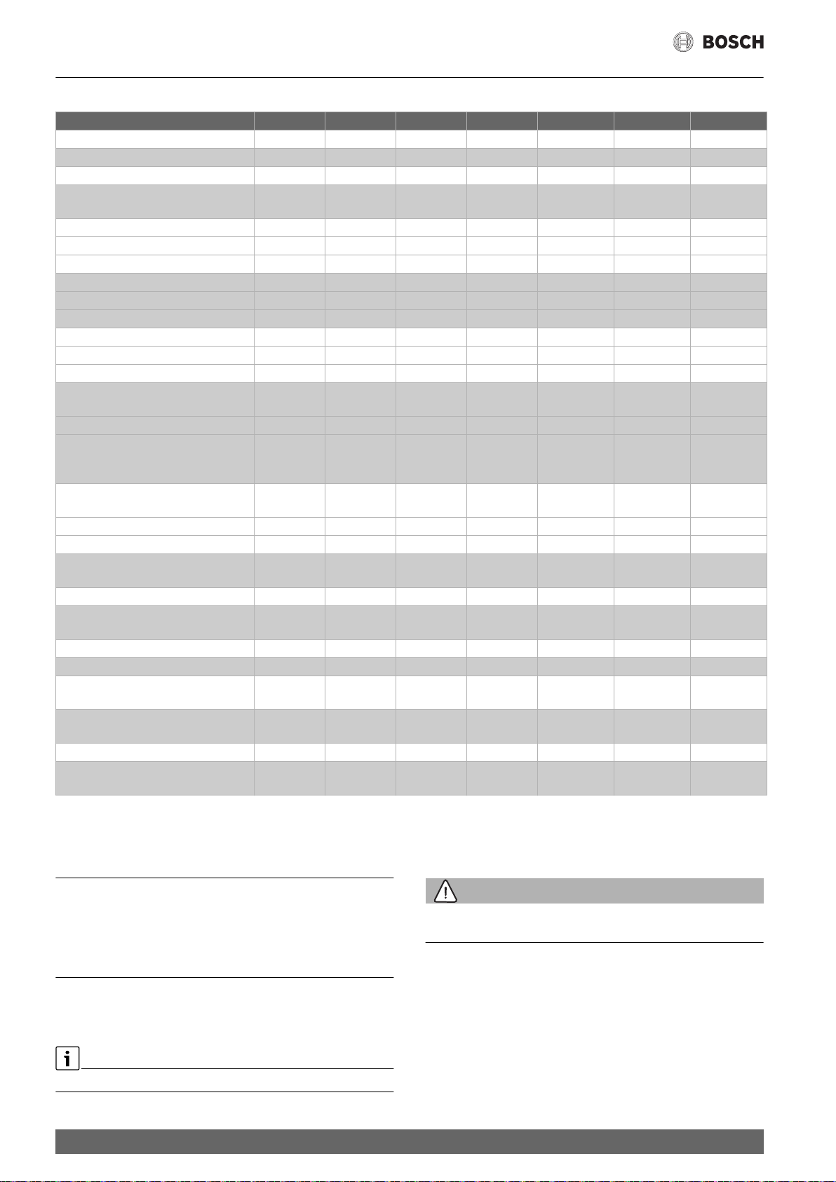
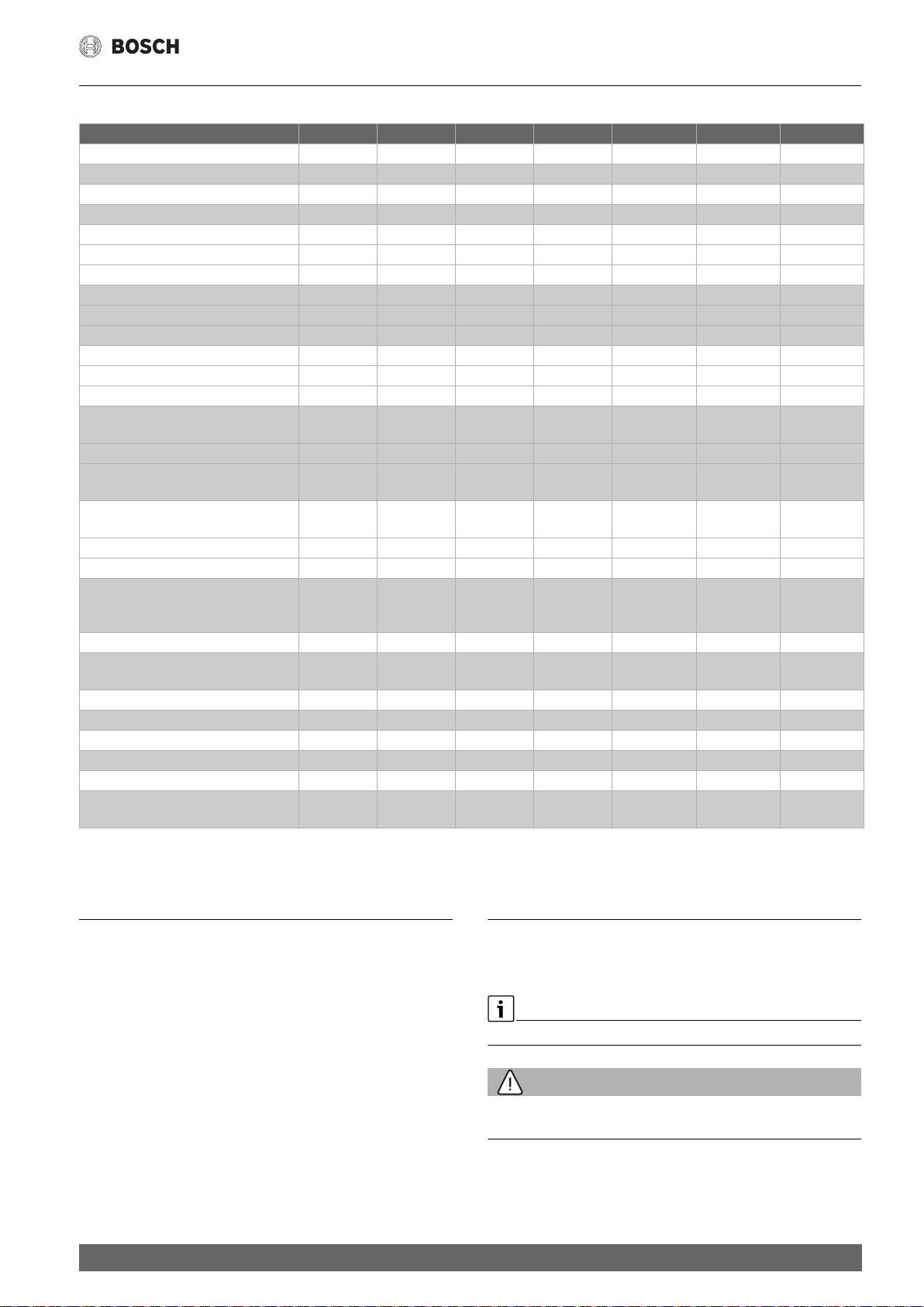
3 Technische Daten
TR2000 12 B TR2000 18 B TR2000 21 B TR2000 24 B TR2000R 18B TR2000R 21B TR2000R 24B
Nennleistung [kW] 13,2 18 21 24 18 21 24
Nennspannung [V] 400V 3~ 400V 3~ 400V 3~ 400V 3~ 400V 3~ 400V 3~ 400V 3~
Absicherung [A] 25 32 32 40 32 32 40
Minimaler Leiterquerschnitt [mm2] ** 2.5 4 4 6 6 4 6
Sparstellung e [kW]
1. Stufe – – – – 6 7 8
2. Stufe 8 12 14 16 12 14 16
Starkheizung II [kW]
1. Stufe – – – – 9 10,5 12
2. Stufe 12 18 21 24 18 21 24
Einschaltpunkt [l/min]
1. Stufe – – – – 4,0 4,5 5,0
2. Stufe 3,6 5,0 5,8 6,6 5,0 5,8 6,6
Mischwasser [l/min] bei Nennleistung
von ca. 38°C 6,6 9,9 11,6 13,2 9,9 11,6 13,2
von ca. 50°C
(Zulauftemperatur 12°C)
Mindestfließdruck am Gerät*
[MPa (bar)]
mit Durchflussbegrenzer 0,03 (0,3) 0,07 (0,7) 0,08 (0,8) 0,09 (0,9) 0,07 (0,7) 0,08 (0,8) 0,09 (0,9)
ohne Durchflussbegrenzer 0,02 (0,2) 0,04 (0,4) 0,05 (0,5) 0,06 (0,6) 0,04 (0,4) 0,05 (0,5) 0,06 (0,6)
Einsatzbereich in Wässern
Spezifischer elektrischer
Widerstand bei 15 °C [Ωcm]
Nenndruck [MPa (bar)] 1 (10) 1 (10) 1 (10) 1 (10) 1 (10) 1 (10) 1 (10)
Maximal zulässige
Zulauf-Temperatur [°C]
Energieeffizienzklasse AAAA A A A
Lastprofil S S S S S S S
Jahresenergieverbrauch [kWh] 480 481 483 483 481 483 483
Täglicher Stromverbrauch [kWh] 2,213 2,215 2,228 2,232 2,215 2,228 2,232
Schallleistungspegel [dB] 15 15 15 15 15 15 15
Warmwasserbereitungs-
Energieeffizienz [%]
* Hierzu kommt noch der Druckabfall an der Mischbatterie.
** Je nach Anschlusskonfiguration können größere Leiterquerschnitte erforderlich sein
4,5 6,8 7,9 9,1 6,8 7,9 9,1
≥ 800 ≥ 1 300 ≥ 1 300 ≥ 1 300 ≥ 1 300 ≥ 1 300 ≥ 1 300
20 20 20 20 20 20 20
38,4 38,4 38,2 38,1 38,4 38,2 38,1
C Abmessungen
4 Sonderzubehör
• Vorrangschalter (Lastabwurfrelais) BZ45L21:
Für den Betrieb mit Vorrangschaltung.
• Montageset BZ45K23: Für Aufputzinstallation.
4
5 Gebrauchsanleitung
Bitte die ausführlichen Sicherheitshinweise am Anfang dieser Anleitung durchlesen und beachten!
Wichtig: Das Gerät niemals Frost aussetzen!
WARNUNG:
Stromschlaggefahr!
Schalten Sie im Fehlerfall sofort die Netzspannung ab!
• Bei einer Undichtigkeit am Gerät sofort die Kaltwasser zuleitung
schließen.
TR2000 | TR2000R – 6 720 876 014 (2018/04)
Reinigung
5.1 Gerät kennenlernen
Der Durchlauferhitzer erwärmt das Wasser, während es durch das Gerät
fließt. Nur in dieser Zeit verbraucht das Gerät Strom.
Bedienelemente (D)
Ihr Durchlauferhitzer hat zwei Heizstufen:
eco Sparstufe – zwei Drittel Leistung
comfort Starkheizung – volle Leistung
Stufe eco ist die ideale Einstellung für:
▶ Waschbecken
▶ Dusche
▶ Bidet
Stufe comfort benutzen Sie bei Verwendung einer Thermostatbatterie,
für hohe Temperaturen oder große Wassermengen, z.B.
▶ Geschirrspülen
▶ Reinigung
▶ Badewanne
5.2 Gerät bedienen
Warmwasserhahn öffnen (Bild 7, E)
Der Durchlauferhitzer schaltet sich ein und erhitzt das Wasser, wenn der
Warmwasserhahn geöffnet wird (Bild E, 1.).
Er schaltet sich wieder aus, wenn Sie den Wasserhahn schließen.
6 Reinigung
Das Gerät nur feucht abwischen.
Verwenden Sie keine scharfen oder scheuernden Reinigungsmittel.
HINWEIS:
Das Gerät muss normalerweise nicht entkalkt werden. Bei extrem hartem Wasser und häufigem Zapfen von sehr heißem Wasser kann das Gerät aber verkalken. Wenden Sie sich an unseren Kundendienst.
HINWEIS:
Hinweis (nicht bei TR2000 12B …)
Bei nur wenig geöffnetem Warmwasserhahn arbeitet der Durchlauferhitzer in beiden, vorgewählten Stufen (eco, comfort) mit halber Leistung.
Bei ganz geöffnetem Warmwasserhahn arbeitet das Gerät mit voller, vorgewählter Leistung.
Wassertemperatur erhöhen
Warmwasserhahn etwas schließen (Bild 7, E 2.).
Wassertemperatur senken
Kaltwasserhahn öffnen (Bild 7, E 3.).
5.2.1 Inbetriebnahme nach Wasserabschaltung
• Gerät spannungslos machen
(Sicherungen in der Hausinstallation herausdrehen).
• Warmwasserhahn so lange öffnen, bis die Luft aus der Leitung entwichen ist.
• Sicherungen wieder eindrehen.
Das Gerät ist betriebsbereit.
5.2.2 Energie sparen
Bei Temperaturwählerstellung „eco“ wird das Gerät am wirtschaftlichs-
ten betrieben.
Bei Handwaschbecken: Eckregulierventil so weit öffnen, dass sich nur
die kleine Heizleistung einschaltet.
5.2.3 Winterbetrieb
HINWEIS:
Im Winter kann es vorkommen, dass die Zulauftemperatur des Wassers
sinkt und dadurch die gewünschte Auslauftemperatur nicht mehr erreicht wird.
• Um diese Temperaturabsenkung auszugleichen, bitte die Wassermenge am Wasserhahn so weit reduzieren, bis die gewünschte
Warmwassertemperatur erreicht wird.
TR2000 | TR2000R – 6 720 876 014 (2018/04)
5
Eine Störung, was tun?
Funktioniert Ihr Gerät nicht wie gewünscht, so liegt es oft nur an einer
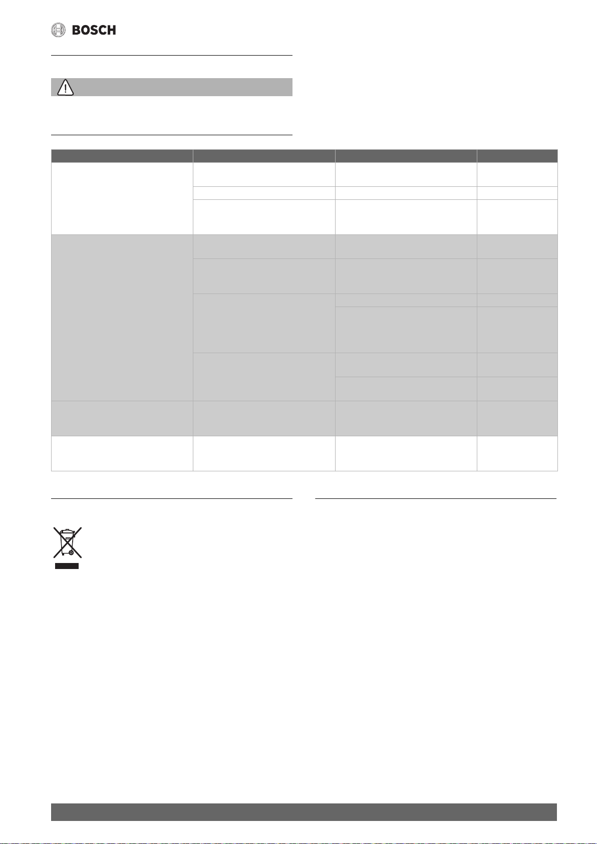
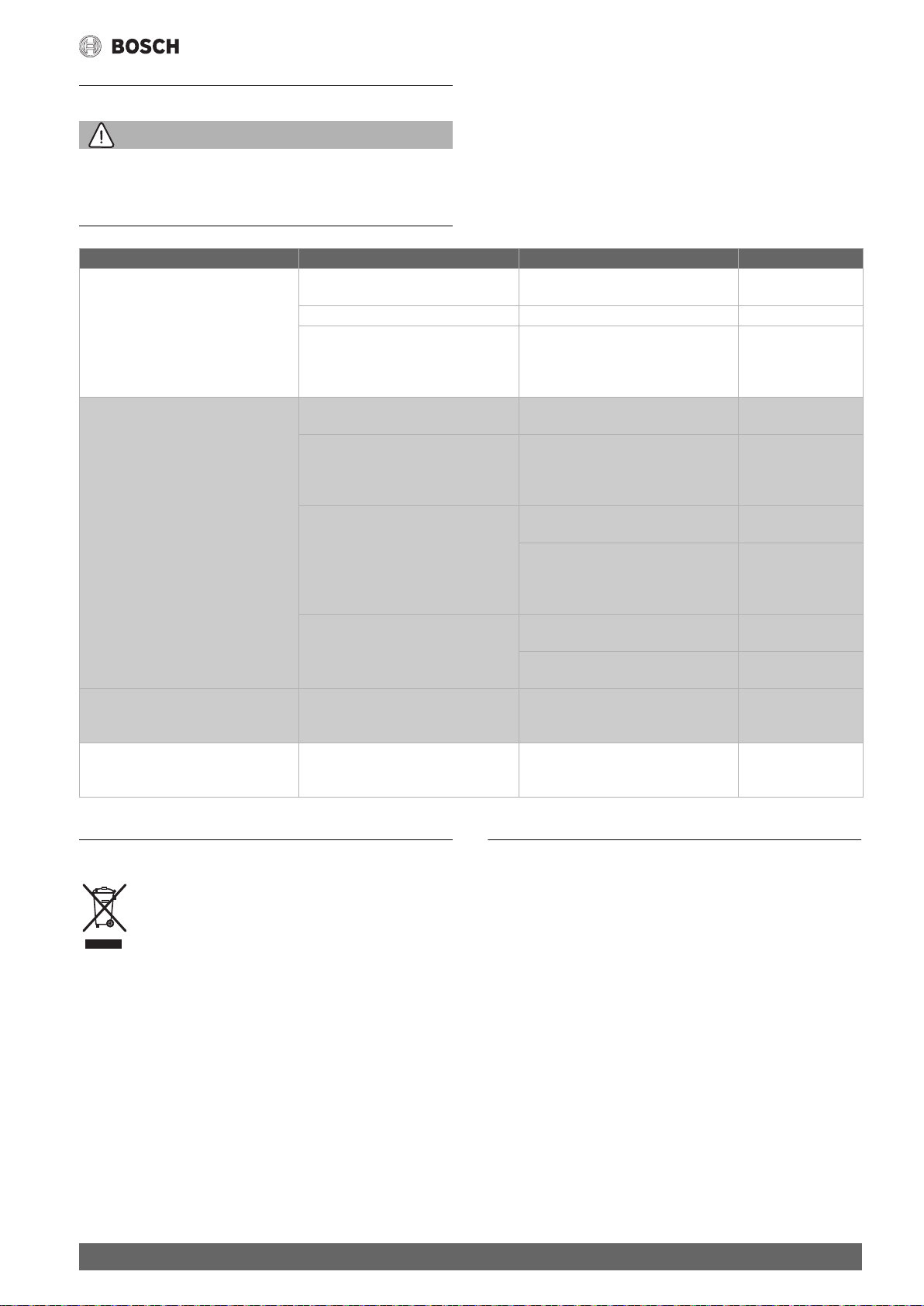
7 Eine Störung, was tun?
WARNUNG:
Achtung!
Reparaturen dürfen nur vom Fachmann durchgeführt werden. Sie setzen
sich großer Gefahr aus, wenn das Gerät unsachgemäß repariert wird.
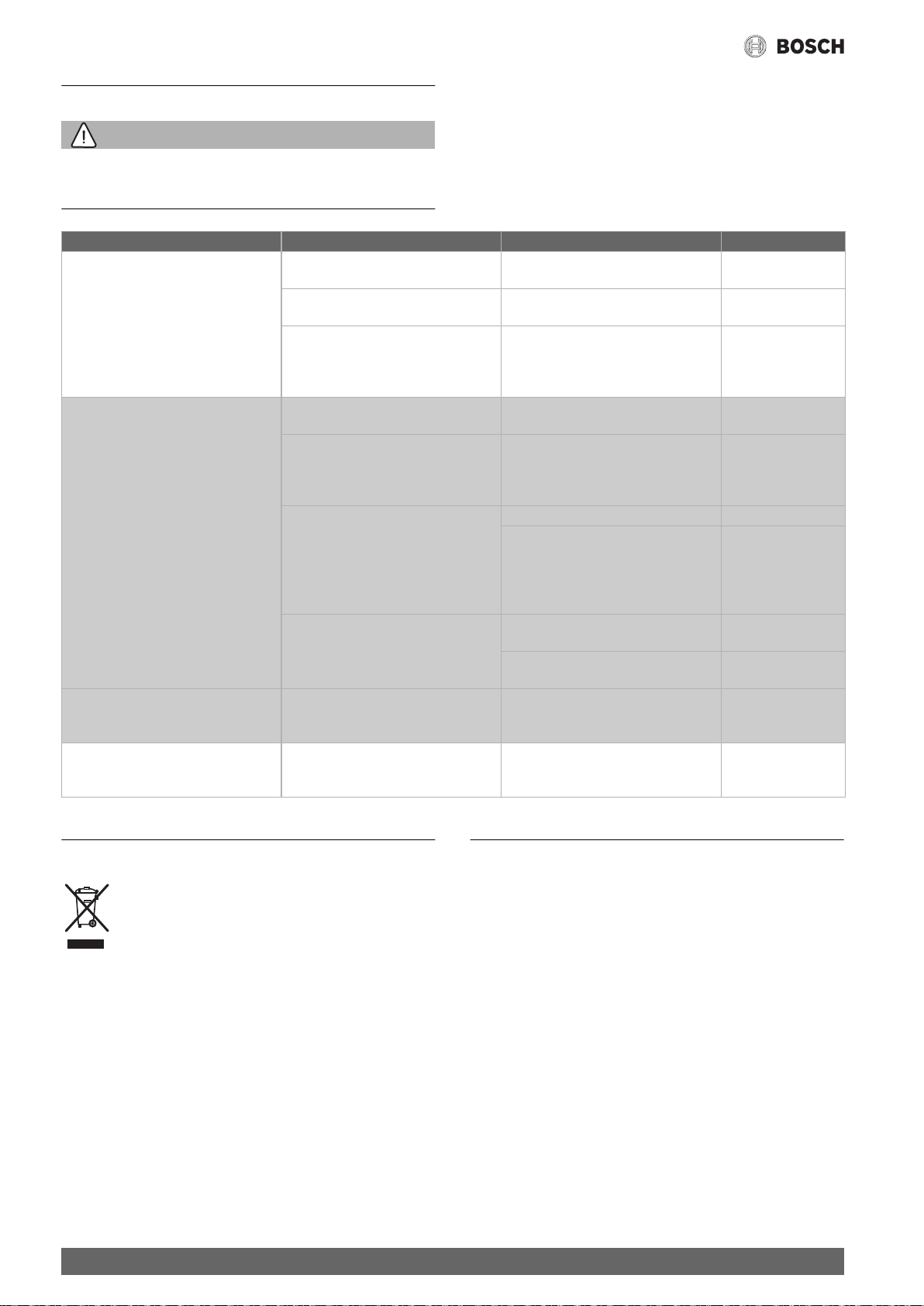
Störung Ursache Behebung Wer
Zu geringer Durchfluss von Wasser.
Das Gerät schaltet nicht ein.
Das Wasser wird nicht ausreichend
warm.
Der Durchlauferhitzer schaltet während
der Wasserentnahme ab, die Wassertemperatur sinkt.
Winterbetrieb:
Die gewünschte Auslauftemperatur wird
im Winter nicht mehr erreicht.
Konnte die Störung nicht behoben werden, bitte den Kundendienst anrufen.
Das Sieb im Wasserhahn oder im Duschkopf ist verstopft.
Das Sieb im Eckregulierventil ist verstopft.
Das Eckregulierventil ist verstopft. Warmwasserhahn ganz öffnen und Eck-
Die Sicherung in der Haus installation hat
ausgelöst.
Der Sicherungsautomat im Gerät hat ausgelöst.
Die Leistungsgrenze ist erreicht.
Zu hoher Durchfluss und/oder zu niedrige Kaltwasser-Zulauftemperatur.
Die zweite Stufe im Gerät schaltet nicht
ein (das hörbare „Klicken“ fehlt).
Quellende Dichtung im Warmwasserhahn
Die Zulauftemperatur ist gesunken. Wassermenge am Wasserhahn so weit
Kleinigkeit. Bitte prüfen Sie, ob aufgrund folgender Hinweise die Störung
selbst behoben werden kann. Sie vermeiden dadurch die Kosten für einen unnötigen Kundendiensteinsatz.
Das Sieb entnehmen und reinigen oder
entkalken.
Das Sieb durch einen Fachmann reinigen
lassen.
regulierventil mehrmals auf- und zudrehen. Anschließend das Sieb am
Wasserhahn reinigen.
Die Sicherung in der Haus installation
überprüfen.
Den Sicherungsautomaten im Gerät
durch einen Fachmann überprüfen lassen. Die erlaubte Zulauftemperatur kontrollieren.
Durchfluss am Wasserhahn reduzieren. Kunde
Durch einen Fachmann:
den Durchfluss über das Eckventil regulieren lassen.
Den Durchflussbegrenzer kontrollieren
oder einen kleineren einsetzen.
Das Sieb im Wasserhahn entnehmen und
reinigen oder entkalken.
Das Sieb im Eckregulierventil reinigen
(Bild 6, A 4.).
Im Warmwasserhahn eine nicht quellende Dichtung einsetzen.
reduzieren, bis die gewünschte Warmwassertemperatur erreicht wird.
Kunde
Fachmann
Kunde
Kunde
Fachmann
Fachmann
Kunde
Fachmann
Kunde
Kunde
8 Kundendienst
Wenn Sie den Kundendienst anfordern, geben Sie bitte die Bosch Ordnungsnummer (SNR/TTNR) Ihres Gerätes an.
Sie finden die Nummern auf der Innenseite der aufklapp baren Bedienblende des Durchlauferhitzers.
6
9 Entsorgung
Dieses Gerät ist entsprechend der europäischen Richtlinie
2012/19/EU über Elektro- und Elektronik altgeräte (waste
electrical and elec tronic equipment – WEEE) gekennzeichnet.
Die Richtlinie gibt den Rahmen für eine EU-weit gültige
Rücknahme und Verwertung der Alt geräte vor.
Über aktuelle Entsorgungswege bitte beim Fachhändler informieren.
Änderungen vorbehalten.
TR2000 | TR2000R – 6 720 876 014 (2018/04)
Table of Contents 1 Safety information
1 Safety information . . . . . . . . . . . . . . . . . . . . . . . . . . . . . . . . . . . . 7
2 Installation instructions . . . . . . . . . . . . . . . . . . . . . . . . . . . . . . . 8
2.1 Installation . . . . . . . . . . . . . . . . . . . . . . . . . . . . . . . . . . . . 8
3 Specifications . . . . . . . . . . . . . . . . . . . . . . . . . . . . . . . . . . . . . . . . 9
4 Special accessories . . . . . . . . . . . . . . . . . . . . . . . . . . . . . . . . . . . 9
5 Operating instructions. . . . . . . . . . . . . . . . . . . . . . . . . . . . . . . . . 9
5.1 Getting to know your appliance . . . . . . . . . . . . . . . . . . .10
5.2 Operating the appliance. . . . . . . . . . . . . . . . . . . . . . . . .10
5.2.1 Startup after a water cutoff . . . . . . . . . . . . . . . . . . . . . .10
5.2.2 Saving energy . . . . . . . . . . . . . . . . . . . . . . . . . . . . . . . . .10
5.2.3 Winter operation. . . . . . . . . . . . . . . . . . . . . . . . . . . . . . . 10
This appliance is intended for domestic use and the household
environment only.
• Install and operate the appliance as described in the text and illustrations. We do not accept liability for damage resulting from failure to
heed these instructions.
• This appliance is intended for use up to an altitude of 2000 m above
sea level.
• The appliance may only be installed and stored in a frost-free room
(due to residual water).
WARNING:
Risk of electric shock!
Switch off the mains voltage supply immediately if a fault occurs.
Immediately shut off the cold water supply to the appliance should it
leak.
Table of Contents
6 Cleaning . . . . . . . . . . . . . . . . . . . . . . . . . . . . . . . . . . . . . . . . . . . .10
7 After-sales service . . . . . . . . . . . . . . . . . . . . . . . . . . . . . . . . . . .10
8 A fault, what to do?. . . . . . . . . . . . . . . . . . . . . . . . . . . . . . . . . . . 11
9 Disposal . . . . . . . . . . . . . . . . . . . . . . . . . . . . . . . . . . . . . . . . . . . .11
10 Guarantee . . . . . . . . . . . . . . . . . . . . . . . . . . . . . . . . . . . . . . . . . .11
• The continuous-flow heater may only be connected and put into
operation by a qualified professional.
• In order to avoid potential sources of danger, repairs and
maintenance may only be undertaken by a suitably qualified
specialist.
• Never open the appliance without disconnecting the power
supply beforehand.
• The statutory regulations of the respective country, as well as those
of the local electricity and water suppliers, must be adhered to.
• The continuous-flow heater is a Class I appliance and must be
connected to the protective earth.
• The appliance must be permanently connected to installed pipes.
The conductor cross-section must comply with the installed
appliance power.
CAUTION:
Earthed water pipes may give the appearance of a connected protective
earth.
• To guarantee compliance to relevant safety regulations, an all-pole
separator must be fitted during installation. The contact opening
must be at least 3 mm.
• The continuous-flow heater is only suitable for closed (pressurised)
operation.
• The tap and outlet fittings must be approved for operation with
closed (pressurised) continuous-flow heater systems.
• Only connect the continuous-flow heater to a cold water line.
• The continuous-flow heater is suitable for connection to DVGWtested plastic pipes.
• Disconnect the electrical connection cable from the supply and
shut off the water supply before connecting the appliance!
• Connect the water supply and then connect the electrical supply.
• Only make the openings which are required for installation on the rear
of the appliance. If the appliance is reinstalled, the unused openings
must be provided with watertight sealing.
• Do not touch electrically live parts after installation.
• The appliance should be disconnected from the electrical mains
supply when working on the water supply. After service work is
complete, proceed as during the first-time appliance start-up.
• No changes may be made to the appliance.
• The appliance may only be used for heating drinking water for
household use.
TR2000 | TR2000R – 6 720 876 014 (2018/04)
7
Installation instructions
• This appliance can be used by children aged 8 years and older as well
as by persons with diminished bodily, sensory or mental perception,
or those who lack knowledge or experience, if they are monitored or
have received instruction concerning use and comprehend
the possible dangers that can result. Children may not play with
the appliance. Cleaning and maintenance by the user may not be
performed by unsupervised children.
• Keep children away from the appliance.
• Please monitor children to ensure that they do not play with
the appliance.
• The mixer and the warm water pipe may be hot. Please inform and
instruct children appropriately.
• Do not use aggressive or abrasive cleaning detergents!
• Do not use a steam cleaner.
• The appliance is only to be descaled by a suitably qualified specialist.
Congratulations on purchasing this BOSCH appliance. You have
acquired a top-quality product, which will give you a lot of enjoyment.
Please read this installation and operating instruction manual
carefully, then act accordingly! Store for future reference.
2 Installation instructions
Install the continuous-flow heater as described in the illustrated
section. Observe the instructions in the text.
2.1 Installation
Unpacking/removing the cover (Fig. 1)
• Unpack the appliance and check for transport damage.
• Dispose of the packaging and, where applicable, the old appliance, in
an environmentally conscious manner.
Preparation for installation (Fig. 2)
Important: Only use the enclosed installation set.
• Shut off water supply. The electrical connection (connection cable)
must be disconnected from the power supply. Unscrew the fuse or
switch off the circuit breaker.
Wall mounting (Fig. 3)
• The continuous-flow heater must be fitted securely to the wall.
If required, secure the appliance using the lower adjusting screws.
• The distance from the wall is variable. This allows you to compensate
for any unevenness in the wall surface.
• The sleeve must fit tightly round the connection cable. If the sleeve is
damaged during installation, the holes must be sealed water-tight.
Water connection (Fig. 4)
• The continuous-flow heater must be vented. Open the warm water
tap fully and flush out the appliance thoroughly for 1 minute.
• The flow-rate limiter must be installed in the old water regulating
valve.
Electrical connection (Fig. 5)
• The electrical supply terminal can be fitted at the top or bottom.
The sheath of the connection cable must extend for at least 40 mm
into the appliance.
Installation note
• The installation of non plug-in ready appliances must be undertaken
by the respective utility operator or by a qualified specialist company,
who can also assist you when you are requesting the approval of
the utility company for installation of the appliance.
Startup (Fig. 6/7)
The device is compliant to IEC 61000-3-12.
• At low water pipe pressure, check whether the 2 setting switches
on even when water is drawn from several cold-water taps simultaneously. If not, remove the flow limiter (refer to additional
information 6,A).
• Instruct the user with regard to the operation of the continuous-flow
heater.
Additional information (Fig. 6, A/B)
• If the water pressure of the interior system is low, do not operate
the continuous-flow heater at full power, but remove the flow limiter
(A, 3).
• Priority circuit for the combined operation of electric storage heaters
(B).
8
TR2000 | TR2000R – 6 720 876 014 (2018/04)
Specifications
3 Specifications
TR2000 12 B TR2000 18 B TR2000 21 B TR2000 24 B TR2000R 18B TR2000R 21B TR2000R 24B
Rated power [kW] 13,2 18 21 24 18 21 24
Rated voltage [V] 400V 3~ 400V 3~ 400V 3~ 400V 3~ 400V 3~ 400V 3~ 400V 3~
Fuse protection [A] 25 32 32 40 32 32 40
Minimum conductor cross section
2
[mm
] **
Economy setting e [kW]
1st stage – – – – 6 7 8
2nd stage 8 12 14 16 12 14 16
Intensive setting II [kW]
1st stage – – – – 9 10,5 12
2nd stage 12 18 21 24 18 21 24
Switch-on point [I/min]
1st stage – – – – 4,0 4,5 5,0
2nd stage 3,6 5,0 5,8 6,6 5,0 5,8 6,6
Mixed water [I/min] at rated power
approx. 38°C 6,6 9,9 11,6 13,2 9,9 11,6 13,2
approx. 50 °C
(supply temperature 12 °C)
Minimum flow pressure of appliance*
[MPa (bar)]
with flow limiter 0,03 (0,3) 0,07 (0,7) 0,08 (0,8) 0,09 (0,9) 0,07 (0,7) 0,08 (0,8) 0,09 (0,9)
without flow limiter 0,02 (0,2) 0,04 (0,4) 0,05 (0,5) 0,06 (0,6) 0,04 (0,4) 0,05 (0,5) 0,06 (0,6)
Application area in water specific
electric resistance at 15 °C [Ωcm]
Rated pressure [MPa (bar)] 1 (10) 1 (10) 1 (10) 1 (10) 1 (10) 1 (10) 1 (10)
Maximum permissible supply
temperature [°C]
Energy efficiency class AAAA A A A
Load profile S S S S S S S
Annual energy consumption [kWh] 480 481 483 483 481 483 483
Daily energy consumption [kWh] 2,213 2,215 2,228 2,232 2,215 2,228 2,232
Sound power level [dB] 15 15 15 15 15 15 15
Hot water heating energy efficiency
[%]
* Plus any pressure loss at the tap mixer
** Larger cable cross-sections may be required depending on the connection configuration
2.5 4 4 6 6 4 6
4,5 6,8 7,9 9,1 6,8 7,9 9,1
≥ 800 ≥ 1 300 ≥ 1 300 ≥ 1 300 ≥ 1 300 ≥ 1 300 ≥ 1 300
20 20 20 20 20 20 20
38,4 38,4 38,2 38,1 38,4 38,2 38,1
C Dimensions
4 Special accessories
• Priority switch (load shedding relay) BZ45L21:
for operation with the priority circuit
• Mounting set BZ45K23: for surface-mount installation
TR2000 | TR2000R – 6 720 876 014 (2018/04)
5 Operating instructions
Please read and observe the detailed safety instructions at the start
of these instructions!
Important: The appliance may never be exposed to frost!
WARNING:
Risk of electric shock!
Switch off the mains voltage supply immediately if a fault occurs.
• Immediately shut off the cold water supply to the appliance should
it leak.
9
Cleaning
5.1 Getting to know your appliance
The continuous-flow heater heats the water as it flows through
the appliance. The appliance only consumes power during this period.
Operating elements (D)
The continuous-flow heater has two heat settings:
eco Economy setting – two thirds power
comfort Intensive setting – full power
The eco setting is ideal for:
▶ Wash basin
▶ Shower
▶ Bidet
The comfort setting is used in combination with a thermostaticallycontrolled premixer, for high temperatures or for large volumes of water,
e. g. for:
▶ Dishwashing
▶ Cleaning
▶ Bath tub
5.2 Operating the appliance
Turn on the hot-water tap (Fig. 7,E)
The continuous-flow heater switches on and heats the water when
the hot-water tap is turned on (Fig. 7, E 1).
It switches off again when the tap is turned off.
6 Cleaning
Simply wipe the appliance with a damp cloth.
Do not use acidic or abrasive cleaning materials.
NOTICE:
Notes: It is normally not necessary to descale the appliance. However,
extremely hard water and the frequent flows of very hot water can cause
the appliance to scale up. In this case please contact our after-sales
service.
7 After-sales service
If you call the after-sales service for assistance, please specify the
BOSCH serial number (SNR/TTNR) of your appliance.
These numbers are found on the inside of the swing-out control panel of
the continuous-flow heater.
NOTICE:
Notes (not applicable for TR2000 12B...)
When the water tap is turned on only slightly, the continuous-flow heater
will operate at half power in both of the preselected settings (eco
, comfort). When the water tap is turned on fully, the appliance will
operate at full, preselected power.
Increasing the water temperature (E)
Slightly close the hot-water tap (Fig. E, 2.).
Decreasing the water temperature (E)
Turn on the cold-water tap (Fig. E, 3.).
5.2.1 Startup after a water cutoff
• Disconnect the appliance from the mains supply (remove the fuses
in the fusebox).
• Turn on the hot-water tap until the air is purged from the pipe.
• Reinstall the fuses.
The appliance is ready for operation.
5.2.2 Saving energy
Use the “eco” setting whenever possible.
For wash basins: Open the corner valve to such an extent that only
the lower heat setting switches on.
5.2.3 Winter operation
NOTICE:
Note: It is possible in winter that the supply temperature of the water is
reduced and the required outlet temperature is no longer achieved.
• In order to compensate for this temperature reduction, please reduce
the water quantity on the tap until the required water temperature is
achieved.
10
TR2000 | TR2000R – 6 720 876 014 (2018/04)
If your appliance does not operate as required, it is often due to a very
8 A fault, what to do?
WARNING:
Attention!
Repairs must only be carried out by an authorised technician. Improper
repairs can lead to risk of serious injury to the user.
Fault Cause Solution Who
Water flow-rate is too low.
The appliance does not switch on.
The water is not sufficiently warm. The fuse in the house electrical
The continuous-flow heater switches off
during the drawing-off of water, resulting
in a reduction in the water temperature:
Winter operation:
The desired water temperature leaving
the tap is no longer reached.
If the fault could not be eliminated, please call customer service.
The filter in either the water tap or
the showerhead is clogged.
The filter in the corner valve is clogged. Get a servicing expert to clean the filter. Servicing expert
The corner valve is clogged. Turn on the hot-water tap fully and open
installation has tripped/blown.
The appliance‘s automatic circuit breaker
has been tripped.
The power limit has been reached. Water
flow-rate is too high and/or the cold
water supply temperature is too low.
The second stage in the appliance does
not switch on (the audible “clicking” is
missing).
Swelling seal in the warm water tap A non-swelling sealing material must be
The supply temperature has reduced. Reduce the water flow on the taps until
minor problem. Please check whether you can remedy the fault yourself
by using the following guidelines. You will save yourself the costs of an
unnecessary visit by customer service personnel.
Remove the filter and either clean it or
descale it.
and close the corner valve several times.
Then clean the filter in the water tap.
Check the fuse in the fusebox. Customer
Get the appliance‘s automatic circuit
breaker checked by an electrician. Check
the permissible supply temperature.
Reduce the flow-rate on the tap. Customer
By a qualified professional: use the
corner valve to regulate the flow-rate.
Check the flow-rate limiter or replace it
with a smaller one.
Remove the filter in the tap and either
clean it or descale it.
Clean the filter in the corner valve
(Fig. 6, A 4).
used in the warm water tap.
the desired water temperature is
reached.
Customer
Customer
Servicing expert
Servicing expert
Customer
Servicing expert
Customer
Customer
A fault, what to do?
9 Disposal 10 Guarantee
This appliance is labelled in accordance with European
Directive 2012/19/EU concerning used electrical and
electronic appliances (waste electrical and electronic
equipment – WEEE).
The guideline determines the framework for the return
and recycling of used appliances as appli cable throughout
the EU.
Please ask your specialist retailer about current disposal
facilities.
The guarantee conditions for this appliance are as defined by our
representative in the country in which it is sold.
Details regarding these conditions can be obtained from the dealer from
whom the appliance was purchased. The bill of sale or receipt must be
produced when making any claim under the terms of this guarantee.
Subject to change without notice.
TR2000 | TR2000R – 6 720 876 014 (2018/04)
11
Table des matières
Table des matières 1 Consignes de sécurité
1 Consignes de sécurité . . . . . . . . . . . . . . . . . . . . . . . . . . . . . . . . 12
2 Instructions de montage . . . . . . . . . . . . . . . . . . . . . . . . . . . . . . 13
2.1 Montage . . . . . . . . . . . . . . . . . . . . . . . . . . . . . . . . . . . . . 13
3 Données techniques . . . . . . . . . . . . . . . . . . . . . . . . . . . . . . . . . 14
4 Accessoires en option . . . . . . . . . . . . . . . . . . . . . . . . . . . . . . . . 14
5 Notice d’utilisation. . . . . . . . . . . . . . . . . . . . . . . . . . . . . . . . . . . 14
5.1 Initiation . . . . . . . . . . . . . . . . . . . . . . . . . . . . . . . . . . . . . 15
5.2 Utilisation de l’appareil . . . . . . . . . . . . . . . . . . . . . . . . . 15
5.2.1 Mise en service suite à une coupure d’eau . . . . . . . . . . 15
5.2.2 Economies d’énergie . . . . . . . . . . . . . . . . . . . . . . . . . . . 15
5.2.3 Exploitation en hiver . . . . . . . . . . . . . . . . . . . . . . . . . . . 15
Cet appareil est destiné exclusivement à une utilisation domestique et
non professionnelle.
• Monter et utiliser l’appareil comme indiqué dans le texte et à l’écran.
Nous n’assumons aucune garantie pour les risques susceptibles de
survenir en cas de non-respect de cette notice.
• Cet appareil est destiné à une utilisation jusqu’à une hauteur maximale de 2 000 m au-dessus du niveau de la mer.
• Toujours installer et stocker l’appareil dans une pièce à l’abri du gel
(eau résiduelle).
AVERTISSEMENT :
Danger de choc électrique!
En cas d’erreur, déconnectez immédiatement la tension du secteur.
En cas de fuite sur l’appareil, immédiatement couper l’alimentation en
eau froide.
6 Nettoyage . . . . . . . . . . . . . . . . . . . . . . . . . . . . . . . . . . . . . . . . . . 15
7 Service après-vente. . . . . . . . . . . . . . . . . . . . . . . . . . . . . . . . . . 15
8 En cas de panne que faire ?. . . . . . . . . . . . . . . . . . . . . . . . . . . . 16
9 Élimination . . . . . . . . . . . . . . . . . . . . . . . . . . . . . . . . . . . . . . . . . 16
10 Garantie. . . . . . . . . . . . . . . . . . . . . . . . . . . . . . . . . . . . . . . . . . . . 16
• Seul un installateur agréé est autorisé à raccorder et à mettre en
marche le chauffe-eau instantané.
• Pour éviter tous risques, seul un spécialiste a le droit d’effectuer
des travaux de réparation et de maintenance.
• Nʼouvrez jamais l’appareil sans avoir interrompu l’apport de courant à l’appareil.
• Respectez les prescriptions légales en vigueur dans votre pays ainsi
que celles recommandées par les compagnies locales/nationales distributrices d’électricité et d’eau et applicables dans votre localité.
• Le chauffe-eau instantané est un appareil qui répond à la classe de
protection I. Ildoit être raccordé au fil de terre.
• L’appareil doit être raccordé de manière durable aux conduites d’eau
posées de manière fixe. La section de câble doit correspondre
à la puissance à installer.
PRUDENCE :
Exemple :
Les conduites d’eau mises à la terre peuvent simuler la présence d’un fil
de terre.
• Afin de respecter les prescriptions de sécurité applicables, l’installation doit comporter un dispositif de coupure tous pôles. L’espace
coupe-circuit entre les contacts doit s’élever à 3 mm minimum.
• Le chauffe-eau est conçu uniquement pour fonctionner en circuit
fermé (résistant à la pression).
• La robinetterie doit pouvoir s’utiliser avec des chauffe-eau fermés
(résistants à la pression).
• Ne raccorder le chauffe-eau instantané qu’à une conduite d’eau
froide.
• Le chauffe-eau peut s’utiliser avec de la tuyauterie en matière plastique certifiée DVGW.
• Avant le montage, mettez le câble d’alimentation électrique hors
tension et coupez l’arrivée d’eau!
• Procédez d’abord au raccordement de l’eau, puis au raccordement électrique.
• Réalisez dans la paroi arrière uniquement les ouvertures nécessaires
au montage. Lors du remontage, bouchez les ouvertures inutilisées
afin de les rendre étanches.
• Une fois le montage terminé, les pièces électroconductrices doivent
être impossibles à toucher.
• Toujours débrancher l’appareil du réseau électrique pour effectuer
des travaux sur le réseau d’eau. Après achèvement des travaux, procéder comme pour la première mise en service.
• Il est interdit d’effectuer des modifications sur l’appareil.
12
TR2000 | TR2000R – 6 720 876 014 (2018/04)
Instructions de montage
• L’appareil doit uniquement être utilisé pour chauffer l’eau potable
pour l’usage domestique.
• Cet appareil peut être utilisé par des enfants d’au moins 8 ans ainsi
que par des personnes à capacités physiques, sensorielles ou mentales réduites ou par des personnes à expériences et savoir insuffisants, dans la mesure où ils sont surveillés ou bien qu’ils ont été
informés sur l’utilisation sûre de l’appareil et qu’ils comprennent les
dangers résultant d’une utilisation non conforme. Lesenfants ne
doivent jamais jouer avec l’appareil. Le nettoyage et la maintenance
utilisateur peuvent uniquement être effectués par des enfants s’ils
sont sous surveillance.
• Tenir les enfants à l’écart de l’appareil.
• Surveiller les enfants afin qu’ils ne jouent pas avec l’appareil.
• Le mitigeur et le tuyau d’eau chaude peuvent devenir chauds. En avertir les enfants.
• Ne pas utiliser de détergents agressifs ou solvants.
• Ne pas utiliser de nettoyeur à vapeur.
• Seul un spécialiste a le droit de détartrer l’appareil.
La société BOSCH vous félicite pour l’achat de son appareil. Vous avez
acheté un produit de qualité élevée qui vous apportera beaucoup
de plaisir.
Lire attentivement cette notice de montage et d’utili sation, agir
en conséquence et la conserver !
2 Instructions de montage
Montez le chauffe-eau instantané en suivant les indications portées
sur les figures. Respectez les consignes du texte.
2.1 Montage
Déballage / Enlèvement du capot (Fig. 1)
• Déballez l’appareil et vérifiez s’il n’a pas subi de dégâts pendant
le transport.
• Eliminez l’emballage et, le cas échéant, l’ancien appareil en respectant l’environnement.
Préparation du montage (Fig. 2)
Montage mural (Fig. 3)
• Le chauffe-eau instantané doit être solidement monté contre le mur.
Le cas échéant, fixez-le au moyen des vis de réglage inférieures.
• L’écart par rapport au mur est variable. Vous pouvez ainsi compenser
les inégalités du mur.
• La gaine doit bien enserrer le cordon d’alimentation.
Si elle a été endommagée pendant le montage, bouchez les trous
pour les rendre étanches à l’eau.
Raccordement de l’eau (Fig. 4)
• Le chauffe-eau doit être purgé. Pour ce faire, ouvrir complètement
le robinet d’eau chaude et laisser l’eau s’écouler pendant une minute.
• Le limiteur de débit doit obligatoirement être monté dans la conduite
d’arrivée d’eau froide.
Branchement électrique (Fig. 5)
• La borne de branchement au secteur peut être montée en haut
ou en bas. La gaine du câble d’alimentation doit pénétrer au moins
de 40mm dans l’appareil.
Remarque sur l’installation
• L’installation d’appareils pas prêts au branchement doit être
effectuée par l’exploitant de réseau ou par une entreprise spécialisée
habilitée, laquelle vous aide également à obtenir l’accord
de l’exploitant de secteur respectif pour l’installation de l’appareil.
Mise en service (Fig. 6/7)
L’appareil est conforme à la norme CEI 61000-3-12.
• Par faible pression d’eau, vérifiez si la position 2 s’enclenche automatiquement lorsque plusieurs robinets d’eau froide sont ouverts simultanément. Si elle ne s’enclenche pas, enlevez le limiteur de débit
(voir les informations supplémentaires A).
• Expliquez à l’utilisateur le fonctionnement du chauffe-eau instantané.
Informations supplémentaires (Fig. 6, A/B)
• Si votre installation domestique présente une pression d’eau faible et
si, pour cette raison, le chauffe-eau ne peut pas fonctionner à pleine
puissance, enlevez le limiteur de débit (A, 3).
• Circuit commutateur prioritaire si le chauffe-eau doit être combiné
à des appareils de chauffage électrique à accumulation (B).
Important : utiliser impérativement le jeu de montage joint.
• Fermer l’arrivée d’eau. L’alimentation électrique (câble
d’alimentation électrique) doit être mise hors tension. Retirer
les fusibles ou éteindre l’appareil.
TR2000 | TR2000R – 6 720 876 014 (2018/04)
13
Données techniques
3 Données techniques
TR2000 12 B TR2000 18 B TR2000 21 B TR2000 24 B TR2000R 18B TR2000R 21B TR2000R 24B
Puissance nominale [kW] 13,2 18 21 24 18 21 24
Tension nominale [V] 400V 3~ 400V 3~ 400V 3~ 400V 3~ 400V 3~ 400V 3~ 400V 3~
Protection par fusible [A] 25 32 32 40 32 32 40
Section minimum du conducteur élec-
trique [mm
Réglage Economie e [kW]
1ère position – – – – 6 7 8
2ème position 8 12 14 16 12 14 16
Chauffage intensif II [kW]
1ère position – – – – 9 10,5 12
2ème position 12 18 21 24 18 21 24
Point d’enclenchement [l/min]
1ère position – – – – 4,0 4,5 5,0
2ème position 3,6 5,0 5,8 6,6 5,0 5,8 6,6
Eau mélangée [l/min] à la puissance
nominale
38°C env. 6,6 9,9 11,6 13,2 9,9 11,6 13,2
50°C env.
(Eau arrivant à une température
de 12°C)
Pression d’écoulement minimale
dans l’appareil* [MPa (bar)]
avec limiteur de débit 0,03 (0,3) 0,07 (0,7) 0,08 (0,8) 0,09 (0,9) 0,07 (0,7) 0,08 (0,8) 0,09 (0,9)
sans limiteur de débit 0,02 (0,2) 0,04 (0,4) 0,05 (0,5) 0,06 (0,6) 0,04 (0,4) 0,05 (0,5) 0,06 (0,6)
Rayon d’action dans l’eau Résistance
électrique spécifique à 15 °C [Ωcm]
Pression nominale [MPa (bar)] 1 (10) 1 (10) 1 (10) 1 (10) 1 (10) 1 (10) 1 (10)
Température maximale admissible
à l’entrée [°C]
Classe d’efficacité énergétique AAAA A A A
Profil de soutirage S S S S S S S
Consommation annuelle d’énergie
[kWh]
Consommation quotidienne
de courant [kWh]
Niveau de puissance acoustique [dB] 15 15 15 15 15 15 15
Efficacité énergétique
de la préparation d’eau chaude [%]
* La perte de pression au mitigeur doit y être ajoutée.
**De plus grandes sections de câble peuvent s’avérer nécessaires en fonction de la configuration du raccordement
2
] **
2.5 4 4 6 6 4 6
4,5 6,8 7,9 9,1 6,8 7,9 9,1
≥ 800 ≥ 1 300 ≥ 1 300 ≥ 1 300 ≥ 1 300 ≥ 1 300 ≥ 1 300
20 20 20 20 20 20 20
480 481 483 483 481 483 483
2,213 2,215 2,228 2,232 2,215 2,228 2,232
38,4 38,4 38,2 38,1 38,4 38,2 38,1
C Dimensions
4 Accessoires en option
• Interrupteur de priorité (relais de délestage brusque) BZ45L21 :
pour l’exploitation avec une commutation prioritaire.
• Kit de montage BZ45K23 : pour une installation sur crépi.
5 Notice d’utilisation
Lire et respecter les consignes de sécurité détaillées figurant au
début de cette notice!
Important: ne jamais exposer l’appareil au gel!
14
AVERTISSEMENT :
Danger de choc électrique!
En cas d’erreur, déconnectez immédiatement la tension du secteur.
• En cas de fuite sur l’appareil, immédiatement fermer la conduite
d’eau froide.
TR2000 | TR2000R – 6 720 876 014 (2018/04)
Nettoyage
5.1 Initiation
Le chauffe-eau instantané chauffe l’eau pendant qu’elle circule
à l’intérieur. L’appareil consomme du courant uniquement pendant le
temps de chauffe.
Éléments de commande (D)
Votre chauffe-eau comporte deux positions:
eco Economie – Puissance réduite aux deux tiers
comfort Chauffage intensif – Pleine puissance
La position eco est le réglage idéal pour
▶ le lavabo
▶ la douche
▶ le bidet
Utilisez la position comfort en conjonction avec un mitigeur, pour
obtenir une température élevée ou un grand débit d’eau, parex. pour
▶ laver la vaisselle
▶nettoyer
▶ remplir la baignoire
5.2 Utilisation de l’appareil
Robinet d’eau chaude ouvert (Fig. 7, E)
L’appareil se met en marche et chauffe l’eau lorsque le robinet d’eau
chaude est ouvert (E, 1).
Fermez le robinet d’eau et l’appareil s’éteint à nouveau.
5.2.1 Mise en service suite à une coupure d’eau
• Mettez l’appareil hors tension
(dévissez les fusibles du secteur domestique).
• Laissez le robinet d’eau chaude ouvert jusqu’à ce que l’air se soit
échappé de la conduite.
• Revissez les fusibles.
L’appareil est prêt à fonctionner.
5.2.2 Economies d’énergie
Utilisez aussi souvent que possible la position Economie «eco».
Pour le lavabo: ouvrez le robinet régulateur à équerre de façon à ce que
seule la petite puissance de chauffe s’enclenche.
5.2.3 Exploitation en hiver
AVIS :
Remarque: en hiver, la température d’alimentation de l’eau peut éventuellement diminuer et en conséquence la température de sortie souhaitée risque de ne plus être atteinte.
• Afin de pouvoir compenser cette diminution de la température,
réduire la quantité d’eau sur le robinet d’eau de manière à atteindre
la température souhaitée pour l’eau chaude.
6 Nettoyage
Essuyez l’appareil uniquement avec un chiffon humide.
N’utilisez aucun détergent abrasif ou récurant.
AVIS :
Remarque (ne s’applique pas aux modèles TR2000 12B...)
Robinet d’eau chaude légèrement ouvert, le chauffe-eau fonctionne
à la moitié de sa puissance dans l’une ou l’autre des positions
(eco, comfort) présélectionnées. Robinet d’eau chaude complètement
ouvert, l’appareil fonctionne à la pleine puissance présélectionnée.
Pour hausser la température de l’eau (E)
Refermez légèrement le robinet d’eau chaude (Figure 7, E 2).
Pour diminuer la température de l’eau (E)
Ouvrez le robinet d’eau froide (Figure 7, E 3).
AVIS :
Remarque: l’appareil ne nécessite normalement pas de détartrage.
Néanmoins, si l’eau de votre région est extrêmement dure et si vous prélevez fréquemment de l’eau très chaude, l’appareil risque de s’entartrer.
Veuillez vous adresser à notre service après-vente.
7 Service après-vente
Lorsque vous faites appel au service après-vente, veuillez indiquer
les numéros BOSCH (SNR/TTNR) de votre appareil.
Vous trouverez ces numéros à l’intérieur du bandeau de commande
dépliant du chauffe-eau instantané.
TR2000 | TR2000R – 6 720 876 014 (2018/04)
15
En cas de panne que faire ?
Si votre appareil ne fonctionne pas tel que désiré, la cause est souvent
8 En cas de panne que faire ?
AVERTISSEMENT :
Attention!
Les réparations ne doivent être effectuées que par un installateur agréé.
Un appareil mal réparé peut être très dangereux.
Panne Cause Remède Qui ?
Débit d’eau trop faible. L’appareil ne se
met pas en marche.
L’eau n’est pas suffisamment chaude. Le fusible dans l’installation domestique
L’appareil se met hors marche pendant le
prélèvement d’eau chaude, la
température de l’eau baisse.
Exploitation en hiver:
La température de sortie désirée n’est
plus atteinte en hiver.
Si la panne n’a pas pu être éliminée, veuillez appeler le service après-vente.
Le crible du robinet ou de la poire
de douche est bouché.
Le crible du robinet régulateur à équerre
est bouché.
Le robinet régulateur à équerre est
bouché.
s’est déclenché.
Le coupe-circuit automatique de
l’appareil s’est déclenché.
La limite de puissance est atteinte. Débit
trop élevé et/ou température d’arrivée
d’eau froide trop faible.
Le second niveau de l’appareil ne
s’allume pas (le « clic » audible manque).
Joint gonflant dans le robinet d’eau
chaude
La température d’arrivée a baissé. Réduire le débit d’eau sur le robinet d’eau
minime. Veuillez contrôler si la panne peut être éliminée d’elle-même en
se basant sur les conseils suivants. Vous pouvez de la sorte éviter une
intervention du service après-vente et donc économiser des frais.
Retirer le crible, le nettoyer ou
le détartrer.
Faire nettoyer le crible par un technicien
spécialisé.
Ouvrez le robinet d’eau chaude en grand
puis ouvrez et fermez à plusieurs reprises
le robinet régulateur à équerre. Ensuite,
nettoyez le crible du robinet d’eau.
Contrôler le fusible dans l’installation
domestique.
Laisser contrôler le coupe-circuit
automatique de l’appareil par un
technicien spécialisé. Contrôler la
température d’arrivée admissible.
Réduire le débit au niveau du robinet. Client
Par un technicien spécialisé: laisser
réguler le débit via une soupape
d’équerre.
Contrôler le limiteur de débit ou utiliser
un plus petit
Retirer le crible du robinet et le nettoyer
ou le détartrer.
Nettoyer le crible du robinet régulateur
à équerre (Fig. 6, A 4)
Appliquer un joint non gonflant dans le
robinet d’eau chaude.
jusqu’à ce que la température d’eau
chaude désirée soit atteinte.
Client
Spécialiste
Client
Client
Spécialiste
Spécialiste
Client
Spécialiste
Client
Client
9 Élimination 10 Garantie
Cet appareil est marqué selon la directive européenne
2012/19/UE relative aux appareils électriques et électroniques usagés (waste electrical and electronic equipment –
WEEE).
La directive définit le cadre pour une reprise et une récupération des appareils usagés applicables dans les pays
de la CE.
S’informer auprès du revendeur sur la procédure actuelle
de recyclage.
16
Les conditions de garantie applicables sont celles publiées par notre distributeur dans le pays où a été effectué l’achat. Le revendeur chez qui
vous vous êtes procuré l’appareil fournira les modalités de garantie sur
simple demande de votre part.
En cas de recours en garantie, veuillez toujours vous munir de la preuve
d’achat.
Sous réserve de modifications.
TR2000 | TR2000R – 6 720 876 014 (2018/04)
Inhoudsopgave 1 Veiligheidsvoorschriften
1 Veiligheidsvoorschriften. . . . . . . . . . . . . . . . . . . . . . . . . . . . . .17
2 Montagehandleiding . . . . . . . . . . . . . . . . . . . . . . . . . . . . . . . . .18
2.1 Montage . . . . . . . . . . . . . . . . . . . . . . . . . . . . . . . . . . . . .18
3 Technische gegevens . . . . . . . . . . . . . . . . . . . . . . . . . . . . . . . . .19
4 Speciaal toebehoren . . . . . . . . . . . . . . . . . . . . . . . . . . . . . . . . .19
Dit apparaat is alleen bestemd voor huishoudelijk gebruik en
de huiselijke omgeving.
• Het apparaat installeren en gebruiken zoals beschreven in de tekst en
de afbeeldingen. Wij zijn niet aansprakelijk voor schade die door het
niet in acht nemen van deze gebruikshandleiding ontstaat.
• Dit apparaat is bedoeld voor gebruik tot een hoogte van 2 000 m bo-
ven de zeespiegel.
• Het apparaat in een vorstvrije ruimte installeren en opslaan (restwater).
Inhoudsopgave
5 Gebruikshandleiding . . . . . . . . . . . . . . . . . . . . . . . . . . . . . . . . .19
5.1 Apparaat leren kennen . . . . . . . . . . . . . . . . . . . . . . . . . .20
5.2 Het apparaat gebruiken . . . . . . . . . . . . . . . . . . . . . . . . .20
5.2.1 Ingebruikneming nadat het water afgesloten
is geweest . . . . . . . . . . . . . . . . . . . . . . . . . . . . . . . . . . . . 20
5.2.2 Energiebesparing . . . . . . . . . . . . . . . . . . . . . . . . . . . . . .20
5.2.3 Winterbedrijf. . . . . . . . . . . . . . . . . . . . . . . . . . . . . . . . . .20
6 Reinigen . . . . . . . . . . . . . . . . . . . . . . . . . . . . . . . . . . . . . . . . . . . .20
7 Klantenservice . . . . . . . . . . . . . . . . . . . . . . . . . . . . . . . . . . . . . .20
8 Wat te doen bij een storing? . . . . . . . . . . . . . . . . . . . . . . . . . . .21
9 Afvoer van afval . . . . . . . . . . . . . . . . . . . . . . . . . . . . . . . . . . . . .21
10 Garantie . . . . . . . . . . . . . . . . . . . . . . . . . . . . . . . . . . . . . . . . . . . .21
WAARSCHUWING:
Gevaar voor een elektrische schok!
Schakel in het geval van een storing de netspanning onmiddellijk uit.
Bij een lekkage aan het apparaat onmiddellijk de koudwatertoevoer
afsluiten.
• De doorstroomgeiser mag alleen door een vakman aangesloten
en in bedrijf genomen worden.
• Om gevaren te voorkomen, mogen reparaties en onderhoud alleen worden uitgevoerd door een vakman.
• Open het apparaat nooit zonder eerst de stroomtoevoer naar het
apparaat onderbroken te hebben.
• De geldende wettelijke voorschriften en de voorschriften van de elektriciteits- en waterbedrijven moeten in acht worden genomen.
• De doorstroomgeiser is een apparaat van isolatieklasse I en moet
worden geaard.
• Het apparaat moet duurzaam aan vast geïnstalleerde leidingen worden aangesloten. De doorsnede van de leiding moet overeenstem-
men met het te installeren vermogen.
VOORZICHTIG:
Geaarde waterleidingen kunnen de aanwezigheid van een aardleiding
ten onrechte aannemelijk maken.
• Om aan de geldende veiligheidsvoorschriften te voldoen, moet in
de installatie een onderbrekingsvoorziening voor alle polen aanwezig
zijn. De contactopening moet minstens 3 mm bedragen.
• De doorstroomgeiser is alleen geschikt voor gesloten (drukvast)
gebruik.
• Armaturen moeten zijn goedgekeurd voor gebruik met gesloten
(drukvaste) doorstroomgeisers.
• Sluit de doorstroomgeiser alleen op een koudwaterleiding aan.
• De doorstroomgeiser is geschikt voor de aansluiting aan DVGWgekeurde kunststofbuizen.
• Maak de elektrische aansluitkabel vóór de montage spannings-
loos en sluit de watertoevoer af.
• Voer de elektrische aansluiting pas na de wateraansluiting uit.
• Maak in de achterwand alleen de openingen die voor de montage nodig zijn. Bij een nieuwe montage moeten de ongebruikte openingen
waterdicht worden afgesloten.
• Spanningvoerende delen mogen na de montage niet meer aanraakbaar zijn.
• Haal de stekker uit het stopcontact bij werkzaamheden aan de waterleiding. Na afronding van de werkzaamheden te werk gaan als bij
de eerste ingebruikstelling.
• Aan het apparaat mogen geen wijzigingen plaatsvinden.
• Het apparaat mag alleen worden gebruikt voor het verwarmen van
water voor huishoudelijk gebruik.
TR2000 | TR2000R – 6 720 876 014 (2018/04)
17

Montagehandleiding
• Dit apparaat mag door kinderen van 8 en ouder en personen met be-
perkte fysieke, zintuiglijke of verstandelijke vermogens of gebrek aan
ervaring en kennis worden gebruikt, mits ze onder toezicht staan of
zijn geïnstrueerd in het veilig gebruik van het apparaat en de daaruit
voortvloeiende risico’s begrijpen. Kinderen mogen niet met het ap-
paraat spelen. Reiniging en gebruikersonderhoud mogen niet zon-
der toezicht door kinderen worden uitgevoerd.
• Houd kinderen bij het apparaat weg.
• Houd toezicht op kinderen om te voorkomen dat ze met het apparaat
spelen.
• De mengkraan en de warmwatertoevoer kunnen heet worden. Attendeer kinderen daarop.
• Gebruik geen schuurmiddelen of bijtende schoonmaakmiddelen.
• Gebruik geen stoomreiniger.
• Het ontkalken van het apparaat moet worden uitgevoerd door een
vakman.
Van harte gefeliciteerd met de aankoop van dit apparaat van ons bedrijf
BOSCH. U hebt een product van hoge kwaliteit aangeschaft, waaraan
u veel plezier zult beleven.
Lees de installatie- en gebruikshandleiding goed door, handel ernaar en bewaar hem goed!
2 Montagehandleiding
Monteer de doorstroomgeiser zoals beschreven in het gedeelte met
afbeeldingen. Neem de aanwijzingen in de tekst in acht.
2.1 Montage
Uitpakken/kap verwijderen (Afb. 1)
• Het apparaat uitpakken en controleren op transportschade.
• De verpakking en eventueel het oude apparaat op milieuvriendelijke
wijze afvoeren.
Montagevoorbereidingn (Afb. 2)
Belangrijk: Uitsluitend de bijgeleverde montageset gebruiken.
Muurmontage (Afb. 3)
• De doorstroomgeiser moet vast op de muur worden gemonteerd.
Bevestig het apparaat eventueel aan de onderste stelschroeven.
• De afstand tot de muur is variabel. Zo kunnen oneffen heden van
de muur worden gecompenseerd.
• De tule moet de aansluitkabel nauw omsluiten. Als de tule beschadigd raakt tijdens de montage, moeten de gaten waterdicht worden
afgesloten.
Wateraansluiting (Afb. 4)
• De doorstroomgeiser moet worden ontlucht. Open daarvoor de warmwaterkraan helemaal en spoel het toestel gedurende één minuut
door.
• Altijd de debietbegrenzer in de koudwatertoevoer inbouwen.
Elektrische aansluiting (Afb.5)
• De netaansluitklem kan boven of beneden gemonteerd worden.
De mantel van de aansluitkabel moet minstens 40 mm in het toestel
naar binnen steken.
Installatie-instructie
• De installatie van niet-insteekbare apparaten moeten worden
uitgevoerd door de netbeheerder of door een erkend vakbedrijf,
dat u ook graag van dienst is bij het verkrijgen van de toestemming
van de netbeheerder voor de installatie van het apparaat.
Ingebruikneming (Afb. 6/7)
Het apparaat voldoet aan IEC 61000-3-12.
• Controleer of bij een lage waterleidingdruk stand II ook wordt ingeschakeld wanneer er water uit meerdere koudwaterkranen wordt afgetapt. Als dit niet het geval is, verwijdert u de doorstroombegrenzer
(zie de aanvullende informatie A).
• Leg de gebruiker uit hoe de doorstroomgeiser wordt bediend.
Aanvullende informatie (Afb. 6 A/B)
• Als de doorstroomgeiser wegens een te lage waterdruk in de huisinstallatie niet het volledige vermogen bereikt, verwijdert u de doorstroombegrenzer (A, 3).
• Voorrangsschakeling voor de combinatie met elektrische boilers
(B).
• Watertoevoer afsluiten. De elektrische aansluiting (aansluitkabel)
moet spanningvrij zijn. Zekeringen uitdraaien of uitschakelen.
18
TR2000 | TR2000R – 6 720 876 014 (2018/04)
Technische gegevens
3 Technische gegevens
TR2000 12 B TR2000 18 B TR2000 21 B TR2000 24 B TR2000R 18B TR2000R 21B TR2000R 24B
Nominaal vermogen [kW] 13,2 18 21 24 18 21 24
Nominale spanning [V] 400V 3~ 400V 3~ 400V 3~ 400V 3~ 400V 3~ 400V 3~ 400V 3~
Beveiliging [A] 25 32 32 40 32 32 40
Minimale geleiderdiameter [mm2] ** 2.5 4 4 6 6 4 6
Spaarstand e [kW]
1e stand – – – – 6 7 8
2e stand 8 12 14 16 12 14 16
Intensieve verwarming II [kW]
1e stand – – – – 9 10,5 12
2e stand 12 18 21 24 18 21 24
Inschakelpunt [l/min]
1e stand – – – – 4,0 4,5 5,0
2e stand 3,6 5,0 5,8 6,6 5,0 5,8 6,6
Mengwater [l/min] bij nominaal
vermogen
van ca. 38°C 6,6 9,9 11,6 13,2 9,9 11,6 13,2
van ca. 50°C
(aanvoertemperatuur 12°C)
Minimale stromingdruk op het
apparaat* [MPa (bar)]
met doorstroombegrenzer 0,03 (0,3) 0,07 (0,7) 0,08 (0,8) 0,09 (0,9) 0,07 (0,7) 0,08 (0,8) 0,09 (0,9)
zonder doorstroombegrenzer 0,02 (0,2) 0,04 (0,4) 0,05 (0,5) 0,06 (0,6) 0,04 (0,4) 0,05 (0,5) 0,06 (0,6)
Toepassingsbereik bij water met een
specifieke elektrische weerstand op
15°C [Ωcm]
Nominale druk [MPa (bar)] 1 (10) 1 (10) 1 (10) 1 (10) 1 (10) 1 (10) 1 (10)
Maximaal toegestane
toevoertemperatuur [°C]
Energie-efficiëntieklasse AAAAA A A
Capaciteitsprofiel S S S S S S S
Jaarlijks energieverbruik [kWh] 480 481 483 483 481 483 483
Dagelijks stroomverbruik [kWh] 2,213 2,215 2,228 2,232 2,215 2,228 2,232
Geluidsniveau [dB] 15 15 15 15 15 15 15
Warmwaterbereiding-energie-
efficiëntie [%]
* Dit is exclusief de drukvermindering bij de mengkraan
**Grotere kabeldiameters kunnen nodig zijn afhankelijk van de aansluitconfiguratie
4,5 6,8 7,9 9,1 6,8 7,9 9,1
≥ 800 ≥ 1 300 ≥ 1 300 ≥ 1 300 ≥ 1 300 ≥ 1 300 ≥ 1 300
20 20 20 20 20 20 20
38,4 38,4 38,2 38,1 38,4 38,2 38,1
C Afmetingen
4 Speciaal toebehoren
• Voorrangschakelaar (ontlastrelais) BZ45L21: voor gebruik met voor-
rangschakeling.
• Montageset BZ45K23: voor opbouwmontage.
TR2000 | TR2000R – 6 720 876 014 (2018/04)
5 Gebruikshandleiding
A.u.b. de uitvoerige veiligheidsinstructies aan het begin van deze
handleiding lezen en ze in acht nemen!
Belangrijk: Het apparaat nooit aan vorst blootstellen!
WAARSCHUWING:
Gevaar voor een elektrische schok!
Schakel in het geval van een storing de netspanning onmiddellijk uit.
• Bij een lekkage aan het apparaat onmiddellijk de koud watertoevoer
afsluiten.
19
Reinigen
5.1 Apparaat leren kennen
De doorstroomgeiser verwarmt het water terwijl het door het apparaat
stroomt. Alleen in deze tijd verbruikt het apparaat stroom.
Bedieningsonderdelen (D)
De doorstroomgeiser heeft twee verwarmingsstanden:
eco spaarstand – tweederde van het vermogen
comfort intensieve verwarming – volledig vermogen
Stand eco is de ideale instelling voor:
▶ wastafel
▶ douche
▶ bidet
Stand comfort gebruikt u bij toepassing van een thermostaatkraan, voor
hoge temperaturen of grote hoeveelheden water, bijv.
▶ afwassen
▶ schoonmaken
▶ badkuip
5.2 Het apparaat gebruiken
Warmwaterkraan openen (E)
De doorstroomgeiser schakelt zichzelf in en verwarmt het water zodra
de warmwaterkraan wordt geopend (afb. 7,E 1).
Het apparaat schakelt zichzelf weer uit wanneer u de kraan sluit.
5.2.1 Ingebruikneming nadat het water afgesloten is geweest
• Het apparaat spanningsloos maken
(zekeringen van de huisinstallatie uitschakelen).
• De warmwaterkraan openen totdat alle lucht uit de leiding is verdwenen.
• Zekeringen weer inschakelen.
Het apparaat is klaar voor gebruik.
5.2.2 Energiebesparing
Gebruik zoveel mogelijk de spaarstand “eco”.
Bij wastafels: het haakse regelventiel zover openen dat alleen het klein-
ste verwarmingsvermogen wordt ingeschakeld.
5.2.3 Winterbedrijf
OPMERKING:
In de winter kan het gebeuren dat de toevoertemperatuur van het water
daalt en daardoor de gewenste uitlooptemperatuur niet wordt bereikt.
• Om deze temperatuursdaling te compenseren, de hoeveelheid water
uit de waterkraan zodanig verlagen totdat de gewenste
warmwatertemperatuur wordt bereikt.
6 Reinigen
Het apparaat uitsluitend schoonvegen met een vochtige doek.
Gebruik geen bijtende of schurende reinigingsmiddelen.
OPMERKING:
N. B. (geldt niet voor TR2000 12B...)
Als de warmwaterkraan maar een klein beetje is geopend, werkt de
doorstroom geiser in beide ingestelde standen (eco, comfort) slechts
met het halve vermogen. Als de warmwaterkraan volledig is geopend,
werkt het apparaat met het volledige ingestelde vermogen.
Watertemperatuur hoger maken (E)
De warmwaterkraan iets sluiten (afb.7, E 2).
Watertemperatuur lager maken (E)
De koudwaterkraan openen (afb.7, E 3).
OPMERKING:
N. B.: Het apparaat hoeft normaal gesproken niet te worden ontkalkt. Bij
extreem hard water en wanneer er vaak zeer heet water wordt afgetapt,
kan het apparaat echter verkalken. Neem dan contact op met onze klantenservice.
7 Klantenservice
Als u contact opneemt met de klantenservice, dient u het BOSCH het
aantal series (SNR/TTNR) van uw apparaat door te geven.
Deze nummers vindt u op de binnenzijde van het uitklapbare bedieningspaneel van de doorstroomgeiser.
20
TR2000 | TR2000R – 6 720 876 014 (2018/04)
Wat te doen bij een storing?
Als uw apparaat niet werkt zoals gewenst, ligt dit vaak slechts aan een
8 Wat te doen bij een storing?
WAARSCHUWING:
Let op!
Reparaties mogen uitsluitend worden uitgevoerd door een installateur.
U loopt een groot risico indien het apparaat op ondeskundige wijze
wordt gerepareerd.
Storing Oorzaak Oplossing Wie
Te geringe doorstroming van water.
Het toestel schakelt niet in.
Het water wordt niet voldoende warm. De zekering in de huisinstallatie is
De doorstroomgeiser schakelt zichzelf uit
tijdens de waterafname, de
watertemperatuur daalt.
Winterbedrijf:
De gewenste uitlooptemperatuur wordt
in de winter niet meer bereikt.
Neem contact op met de klantenservice als de storing niet kon worden verholpen.
De zeef in de waterkraan of in
de douchekop is verstopt.
De zeef in het hoekventiel is verstopt. Laat de zeef door een vakman reinigen. Vakman
Het hoekventiel is verstopt. De warmwaterkraan volledig openen en
geactiveerd.
De zekeringautomaat in het toestel is
geactiveerd.
De vermogensgrens is bereikt. Te hoge
doorstroming en/of te lage koudwatertoevoertemperatuur.
De tweede trap van het toestel schakelt
niet in (het hoorbare “klikken”
ontbreekt).
Lekkende afdichting in
de warmwaterkraan
De toevoertemperatuur is gedaald. Verminder de waterhoeveelheid met
kleinigheid. Controleer of u met de volgende aanwijzingen de storing zelf
kunt verhelpen. U vermijdt daardoor de kosten voor onnodige
werkzaamheden van de klantenservice.
Verwijder de zeef en reinig of ontkalk
deze.
het haakse regelventiel meermaals openen dichtdraaien. Daarna de zeef van
de kraan reinigen.
De zekering in de huisinstallatie
controleren.
Laat de zekeringautomaat in het toestel
door een vakman controleren.
Controleer de toegestane
toevoertemperatuur.
Doorstroom met de waterkraan
reduceren.
Door een vakman: Laat de doorstroming
via het hoekventiel regelen.
Controleer de doorstroombegrenzer
of pas een kleinere toe.
De zeef uit de waterkraan verwijderen
en reinigen of ontkalken.
De zeef van het hoekventiel reinigen
(afb. 6,A 4).
Een niet-lekkende afdichting in
de warmwaterkraan monteren.
de waterkraan tot de gewenste
warmwatertemperatuur wordt bereikt.
Klant
Klant
Klant
Vakman
Klant
Vakman
Klant
Vakman
Klant
Klant
9 Afvoer van afval 10 Garantie
Dit apparaat is gekenmerkt in overeenstemming met
de Europese richtlijn 2012/19/EU betreffende afgedankte
elektrische en elektronische apparatuur (waste electrical
and electronic equipment – WEEE).
De richtlijn geeft het kader aan voor de in de EU geldige
terugneming en verwerking van oude apparaten.
Raadpleeg uw gespecialiseerde handelaar voor de
geldende voorschriften inzake afvalverwijdering.
TR2000 | TR2000R – 6 720 876 014 (2018/04)
Voor dit apparaat gelden de garantievoorwaarden die worden uitgegeven door de vertegenwoordiging van ons bedrijf in het land van aankoop.
De leverancier bij wie u het apparaat hebt gekocht geeft u hierover graag
meer informatie.
Om aanspraak te maken op de garantie hebt u altijd uw aankoopbewijs
nodig.
Wijzigingen voorbehouden.
21

Spis treści
Spis treści 1 Zasady bezpieczeństwa
1 Zasady bezpieczeństwa . . . . . . . . . . . . . . . . . . . . . . . . . . . . . . 22
2 Instrukcja montażu . . . . . . . . . . . . . . . . . . . . . . . . . . . . . . . . . . 22
2.1 Montaż . . . . . . . . . . . . . . . . . . . . . . . . . . . . . . . . . . . . . . 23
3 Dane techniczne . . . . . . . . . . . . . . . . . . . . . . . . . . . . . . . . . . . . . 24
4 Wyposażenie dodatkowe . . . . . . . . . . . . . . . . . . . . . . . . . . . . . 24
5 Instrukcja użytkowania . . . . . . . . . . . . . . . . . . . . . . . . . . . . . . . 24
5.1 Zapoznawanie się z urządzeniem . . . . . . . . . . . . . . . . . 25
5.2 Obsługiwanie urządzenia. . . . . . . . . . . . . . . . . . . . . . . . 25
5.2.1 Uruchomienie urządzenia po wyłączeniu
dopływu wody . . . . . . . . . . . . . . . . . . . . . . . . . . . . . . . . 25
5.2.2 Oszczędność energii . . . . . . . . . . . . . . . . . . . . . . . . . . . 25
5.2.3 Praca w zimie . . . . . . . . . . . . . . . . . . . . . . . . . . . . . . . . . 25
Urządzenie jest przeznaczone wyłącznie do użytku w gospodarstwie
domowym i podobnych otoczeniach.
• Montować i obsługiwać urządzenie zgodnie ze wskazówkami
w tekście i na ilustracjach. Nie przejmujemy żadnej
odpowiedzialności za szkody, powstałe wwyniku nieprzestrzegania
tej instrukcji.
• Urządzenie jest przeznaczone do użytkowania do wysokości 2 000 m
nad poziomem morza.
• Urządzenie instalować i przechowywać wpomieszczeniach
zabezpieczonych przed mrozem (pozostałości wody).
OSTRZEŻENIE:
Niebezpieczeństwo porażenia prądem!
Wrazie awarii natychmiast wyłączyć zasilanie sieciowe.
W przypadku wystąpienia nieszczelności urządzenia natychmiast
zamknąć dopływ zimnej wody.
6 Czyszczenie. . . . . . . . . . . . . . . . . . . . . . . . . . . . . . . . . . . . . . . . . 25
7 Serwis . . . . . . . . . . . . . . . . . . . . . . . . . . . . . . . . . . . . . . . . . . . . . 25
8 Co zrobić wprzypadku zakłócenia?. . . . . . . . . . . . . . . . . . . . . 26
9 Ekologiczna utylizacja . . . . . . . . . . . . . . . . . . . . . . . . . . . . . . . . 26
10 Gwarancja . . . . . . . . . . . . . . . . . . . . . . . . . . . . . . . . . . . . . . . . . . 26
• Podgrzewacz przepływowy może być podłączany iuruchamiany
wyłącznie przez specjalistę.
• Aby uniknąć zagrożeń, naprawy i prace konserwacyjne mogą być
przeprowadzane tylko przez specjalistę.
• Nigdy nie otwierać urządzenia bez uprzedniego odłączenia go od
zasilania energią elektryczną.
• Należy przestrzegać przepisów ustawowych danego kraju oraz
wymagań lokalnego przedsiębiorstwa elektroenergetycznego
iwodociągowego.
• Podgrzewacz przepływowy jest urządzeniem klasy zabezpieczenia I
imusi być podłączany do przewodu ochronnego.
• Urządzenie musi być trwale podłączone do ułożonych na stałe
rurociągów. Przekrój przewodów musi odpowiadać
zainstalowanej mocy.
OSTROŻNOŚĆ:
Uwaga!
Uziemione przewody wodne mogą symulować istnienie przewodu
ochronnego.
• Dla spełnienia obowiązujących przepisów bezpieczeństwa instalacja
musi być wyposażona wrozłącznik, odcinający wszystkie bieguny
zasilania. Rozwarcie styków musi wynosić co najmniej 3 mm.
• Podgrzewacz przepływowy jest przezna czony tylko do pracy
wsystemie zamkniętym (ciśnieniowym).
• Armatury muszą być dopuszczone do pracy zzamkniętymi
(ciśnieniowymi) podgrzewaczami przepływowymi.
• Podgrzewacz przepływowy należy podłączać wyłącznie do przewodu
zimnej wody.
• Podgrzewacz przepływowy nadaje się do przyłączenia
do przewodów rurowych ztworzywa sztucznego, które posiadają
certyfikat DVGW.
• Przed rozpoczęciem montażu należy odłączyć elektryczny
przewód zasilający od napięcia izamknąć przewód wodny!
• Podłączanie elektryczne należy wykonywać dopiero po
podłączeniu wody.
• Wściance tylnej wykonywać tylko te otwory, które są potrzebne
do montażu. Przy ponownym montażu należy wodoszczelnie zatkać
nieużywane otwory.
• Po zakończeniu montażu nie może istnieć możliwość dotknięcia
elementów pod napięciem.
• Podczas wykonywania prac przy instalacji wodociągowej należy
odłączyć urządzenie od sieci. Po zakończeniu prac należy
postępować zgodnie z opisem w punkcie Pierwsze uruchomienie.
22
TR2000 | TR2000R – 6 720 876 014 (2018/04)
Instrukcja montażu
• Nie dokonywać żadnych zmian urządzenia.
• Urządzenie może być używane wyłącznie do nagrzewania wody
pitnej w gospodarstwach domowych.
• Z urządzenia mogą korzystać dzieci wwieku od lat 8 oraz osoby
z ograniczonymi zdolnościami fizycznymi, sensorycznymi lub
psychicznymi oraz bez doświadczenia lub wiedzy, jeśli będą
nadzorowane lub zostaną zapoznane ze sposobem bezpiecznego
użytkowania urządzenia oraz poinformowane o zagrożeniach
związanych zurządzeniem. Dzieci nie mogą wykorzystywać
urządzenia do zabawy. Nie wolno powierzać dzieciom bez nadzoru
prac związanych zczyszczeniem i konserwacją urządzenia.
• Nie dopuszczać dzieci do urządzenia.
• Nadzorować dzieci, aby zapobiec bawieniu się urządzeniem.
• Bateria i rura ciepłej wody mogą się bardzo nagrzewać. Pouczyć
o tym dzieci.
• Nie używać środków do szorowania lub rozpuszczalników.
• Nie używać myjek parowych.
• Usuwanie osadu kamienia z urządzenia może być dokonywane
wyłącznie przez specjalistów.
Serdecznie gratulujemy nabycia urządzenia produkcji firmy BOSCH.
Nabyli Państwo wysokiej jakości urządzenie, które na pewno przyniesie
Państwu wiele pożytku.
Prosimy uważnie przeczytać niniejszą instrukcję montażu obsługi
i stosować się do niej! Instrukcję należy zachować do późniejszego
wykorzystania!
2 Instrukcja montażu
Montaż podgrzewacza przepływowego należy przeprowadzać
zgodnie zopisem wilustrowanej części. Należy przestrzegać
wskazówek wtekście.
2.1 Montaż
Rozpakowanie/zdejmowanie pokrywy (Rys. 1)
• Urządzenie rozpakować i sprawdzić, czy nie posiada uszkodzeń
powstałych w czasie transportu.
• Opakowanie i stare urządzenie usunąć w sposób zgodny zprzepisami
o ochronie środowiska.
Przygotowanie do montażu (Rys. 2)
Montaż na ścianie (Rys. 3)
• Podgrzewacz przepływowy musi być zamontowany na stałe na
ścianie. W takim przypadku zamocować go na dolnych śrubach
mocujących.
• Odległość od ściany jest różna. W taki sposób można wyrównać
nierówności ściany.
• Tulejka ochronna musi ciasno obejmować przewód elektryczny.
W przypadku uszkodzenia tulejki przy montażu, należy zaślepić
otwory wodoszczelnie.
Przyłącze wody (Rys. 4)
• Przepływowy ogrzewacz wody musi być odpowietrzony. Kran ciepłej
wody całkowicie odkręcić i przez 1 minutę urządzenie płukać.
• Ogranicznik przepływu montować zawsze w dopływie zimnej wody.
Przyłącze elektryczne (Rys. 5)
• Przyłączeniowy zacisk sieciowy może być zamontowany na górze lub
na dole. Izolacja zewnętrzna (płaszcz) kabla przyłączeniowego musi
sięgać przynajmniej na 40 mm wgłąb urządzenia.
Wskazówki instalacyjne
• Instalacja urządzeń nie posiadających gotowego wtyku sieciowego
musi zostać wykonana przez operatora sieci lub przez autoryzowany
zakład specjalistyczny, który pomoże w uzyskaniu zezwolenia
właściwego operatora sieci na instalację tego urządzenia.
Uruchomienie (Rys. 6/7)
Urządzenie spełnia wymagania normy IEC 61000-3-12.
• Sprawdzić, czy przy niskim ciśnieniu wody w sieci wodociągowej
stopień grzejny 2 włącza się nawet przy równoczesnym otwarciu
kilku zaworów czerpalnych zimnej wody. Jeżeli nie, należy usunąć
ogranicznik przepływu (patrz informacja dodatkowa A).
• Proszę wyjaśnić użytkownikowi obsługę podgrzewacza
przepływowego.
Informacje dodatkowe (Rys. 6, A/B)
• Jeżeli podgrzewacz nie włącza swojej pełnej mocy z powodu zbyt
niskiego ciśnienia w domowej sieci wodociągowej, należy usunąć
ogranicznik przepływu (A, 3).
• Włączanie priorytetu dla kombinacji z akumulacyjnym grzejnikiem
elektrycznym (B).
Ważne: Używać tylko dołączonego zestawu montażowego.
• Odciąć przewód zasilający wodą. Przyłącze elektryczne (przewód
przyłączeniowy) musi być odłączony od zasilania energią
elektryczną. Wykręcić lub wyłączyć bezpieczniki.
TR2000 | TR2000R – 6 720 876 014 (2018/04)
23
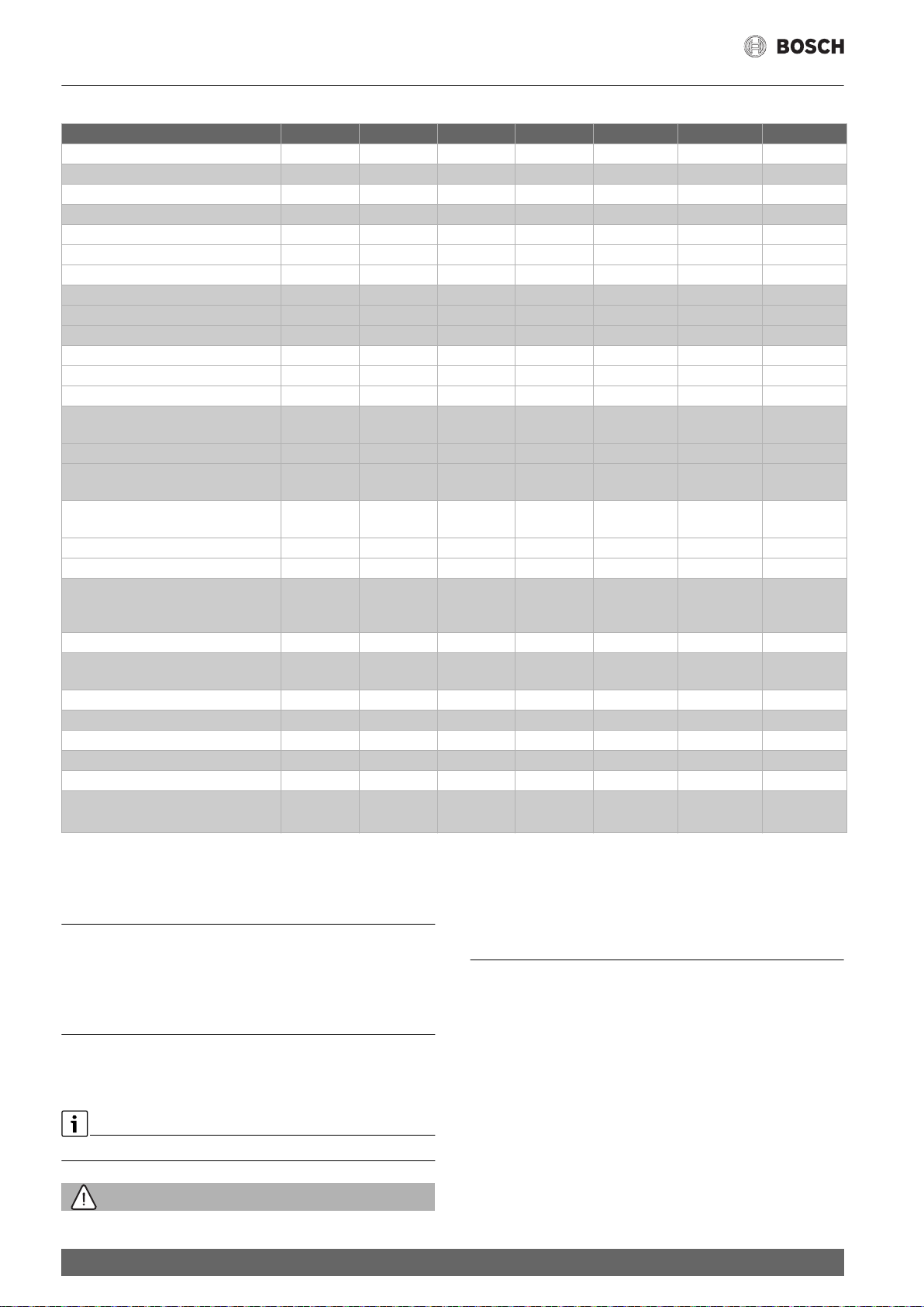
Dane techniczne
3 Dane techniczne
TR2000 12 B TR2000 18 B TR2000 21 B TR2000 24 B TR2000R 18B TR2000R 21B TR2000R 24B
Moc znamionowa [kW] 13,2 18 21 24 18 21 24
Napięcie znamionowe [V] 400V 3~ 400V 3~ 400V 3~ 400V 3~ 400V 3~ 400V 3~ 400V 3~
Zabezpieczenie elektryczne [A] 25 32 32 40 32 32 40
Minimalny przekrój przewodu [mm2] ** 2.5 4 4 6 6 4 6
Nastawienie oszczędne e [kW]
1. stopień – – – – 6 7 8
2. stopień 8 12 14 16 12 14 16
Mocne grzanie II [kW]
1. stopień – – – – 9 10,5 12
2. stopień 12 18 21 24 18 21 24
Punkt włączania [l/min]
1. stopień – – – – 4,0 4,5 5,0
2. stopień 3,6 5,0 5,8 6,6 5,0 5,8 6,6
Natężenie przepływu wody mieszanej
[l/min] przy mocy znamionowej
dla ok. 38°C 6,6 9,9 11,6 13,2 9,9 11,6 13,2
dla ok. 50°C
(temperatura wody dopływowej 12°C)
Minimalne ciśnienie na urządzeniu*
[MPa (bary)]
z ogranicznikiem przepływu 0,03 (0,3) 0,07 (0,7) 0,08 (0,8) 0,09 (0,9) 0,07 (0,7) 0,08 (0,8) 0,09 (0,9)
bez ogranicznika przepływu 0,02 (0,2) 0,04 (0,4) 0,05 (0,5) 0,06 (0,6) 0,04 (0,4) 0,05 (0,5) 0,06 (0,6)
Zakres stosowania dla wody
o oporności elektrycznej właściwej
w temperaturze 15°C [Ωcm]
Ciśnienie znamionowe [MPa (bary)] 1 (10) 1 (10) 1 (10) 1 (10) 1 (10) 1 (10) 1 (10)
Maksymalna dopuszczalna
temperatura dopływu [°C]
Klasa wydajności energetycznej AAAA A A A
Profil obciążenia S S S S S S S
Roczne zużycie energii [kWh] 480 481 483 483 481 483 483
Codzienne zużycie prądu [kWh] 2,213 2,215 2,228 2,232 2,215 2,228 2,232
Poziom mocy akustycznej [dB] 15 15 15 15 15 15 15
Wydajność energetyczna
przygotowywania ciepłej wody [%]
* Tutaj należy uwzględnić dodatkowo spadek ciśnienia na baterii mieszającej
**Mogą być wymagane większe przekroje przewodu wzależności od konfiguracji przyłącza
4,5 6,8 7,9 9,1 6,8 7,9 9,1
≥ 800 ≥ 1 300 ≥ 1 300 ≥ 1 300 ≥ 1 300 ≥ 1 300 ≥ 1 300
20 20 20 20 20 20 20
38,4 38,4 38,2 38,1 38,4 38,2 38,1
C Wymiary
4 Wyposażenie dodatkowe
• Wyłącznik pierwszeństwa (przekaźnik odciążania) BZ45L21:
Do pracy z włączaniem pierwszeństwa.
• Zestaw montażowy BZ45K23: dla instalacji natynkowej.
5 Instrukcja użytkowania
Przeczytać szczegółowe zasady bezpieczeństwa na początku
niniejszej instrukcji i bezwzględnie ich przestrzegać!
Ważne: Nigdy nie narażać urządzenia na działanie mrozu!
OSTRZEŻENIE:
24
Niebezpieczeństwo porażenia prądem!
Wrazie awarii natychmiast wyłączyć zasilanie sieciowe.
• W przypadku wystąpienia nieszczelności urządzenia natychmiast
zamknąć dopływ zimnej wody.
TR2000 | TR2000R – 6 720 876 014 (2018/04)
Czyszczenie
5.1 Zapoznawanie się z urządzeniem
Przepływowy podgrzewacz wody podgrzewa wodę w czasie jej
przepływu przez urządzenie. Tylko w tym czasie urządzenie pobiera prąd
elektryczny.
Elementy obsługi (D)
Pański podgrzewacz przepływowy posiada dwa stopnie grzejne:
eco stopień oszczędny – dwie trzecie mocy całkowitej
comfort mocne podgrzewanie – pełna moc całkowita
Stopień eco jest idealnym nastawieniem przy korzystaniu z ciepłej wody
w takich urządzeniach jak:
▶ umywalka
▶ natrysk
▶ bidet
Stopień comfort stosować w przypadku baterii z termostatem,
zapotrzebowania na wodę o wysokiej temperaturze, albo na dużą ilość
ciepłej wody, np.
▶ zmywanie naczyń
▶ sprzątanie
▶ kąpiel w wannie
5.2 Obsługiwanie urządzenia
Zawór ciepłej wody całkowicie otworzyć (E)
Podgrzewacz przepływowy włącza się automatycznie i podgrzewa wodę,
jeżeli zawór ciepłej wody jest otwarty (Rys. 7, E 1).
Po zamknięciu zaworu ciepłej wody urządzenie samo się wyłącza.
• Aby skompensować ten spadek temperatury należy na tyle
zredukować strumień wody pobieranej z armatury, aż osiągnięta
zostanie wymagana temperatura ciepłej wody.
6 Czyszczenie
Urządzenie wycierać wilgotną ścierką.
Nie używać żadnych ostrych, ani szorujących środków czyszczących!
WSKAZÓWKA:
W normalnym przypadku nie trzeba usuwać zurządzenia kamienia
kotłowego. Jeżeli woda jest bardzo twarda i przy częstym poborze
bardzo gorącej wody może odłożyć się w urządzeniu kamień kotłowy.
Proszę zwrócić się do autoryzowanego punktu serwisowego naszej
firmy.
7 Serwis
W przypadku wezwania serwisu proszę podać numery BOSCH (SNR/
TTNR)urządzenia. Numery te można znaleźć na wewnętrznej stronie
odchylanego pulpitu obsługi podgrzewacza przepływowego.
WSKAZÓWKA:
Wskazówka (nie dla TR2000 12B...)
Jeżeli zawór ciepłej wody otwarty jest tylko trochę, podgrzewacz
przepływowy pracuje w każdym z wybranych stopni (eco, comfort) z
połową mocy. Jeżeli zawór ciepłej wody otwarty jest całkowicie,
urządzenie pracuje z całą mocą, na jaką zostało wstępnie nastawione.
Podwyższanie temperatury wody (E)
Zawór ciepłej wody przymknąć trochę (Rys. 7, E 2).
Obniżanie temperatury wody (E)
Otworzyć zawór zimnej wody (Rys.7, E 3).
5.2.1 Uruchomienie urządzenia po wyłączeniu dopływu wody
• Urządzenie wyłączyć spod napięcia
(wykręcić bezpieczniki domowej sieci elektrycznej).
• Zawór ciepej wody otworzyć na tak długo, aż powietrze wypchnięte
zostanie całkowicie z przewodów rurowych.
• Bezpieczniki ponownie wkręcić.
Urządzenie jest gotowe do pracy.
5.2.2 Oszczędność energii
Używać możliwie często stopień oszczędny „eco“.
Kątowy zawór regulacyjny przy umywalce otworzyć tak daleko,
aby włączał się tylko niski stopień grzejny.
5.2.3 Praca w zimie
WSKAZÓWKA:
W zimie może dojść do spadku temperatury wody zasilającej,
co powoduje, że niemożliwe jest osiągnięcie wymaganej temperatury
na wylocie.
TR2000 | TR2000R – 6 720 876 014 (2018/04)
25
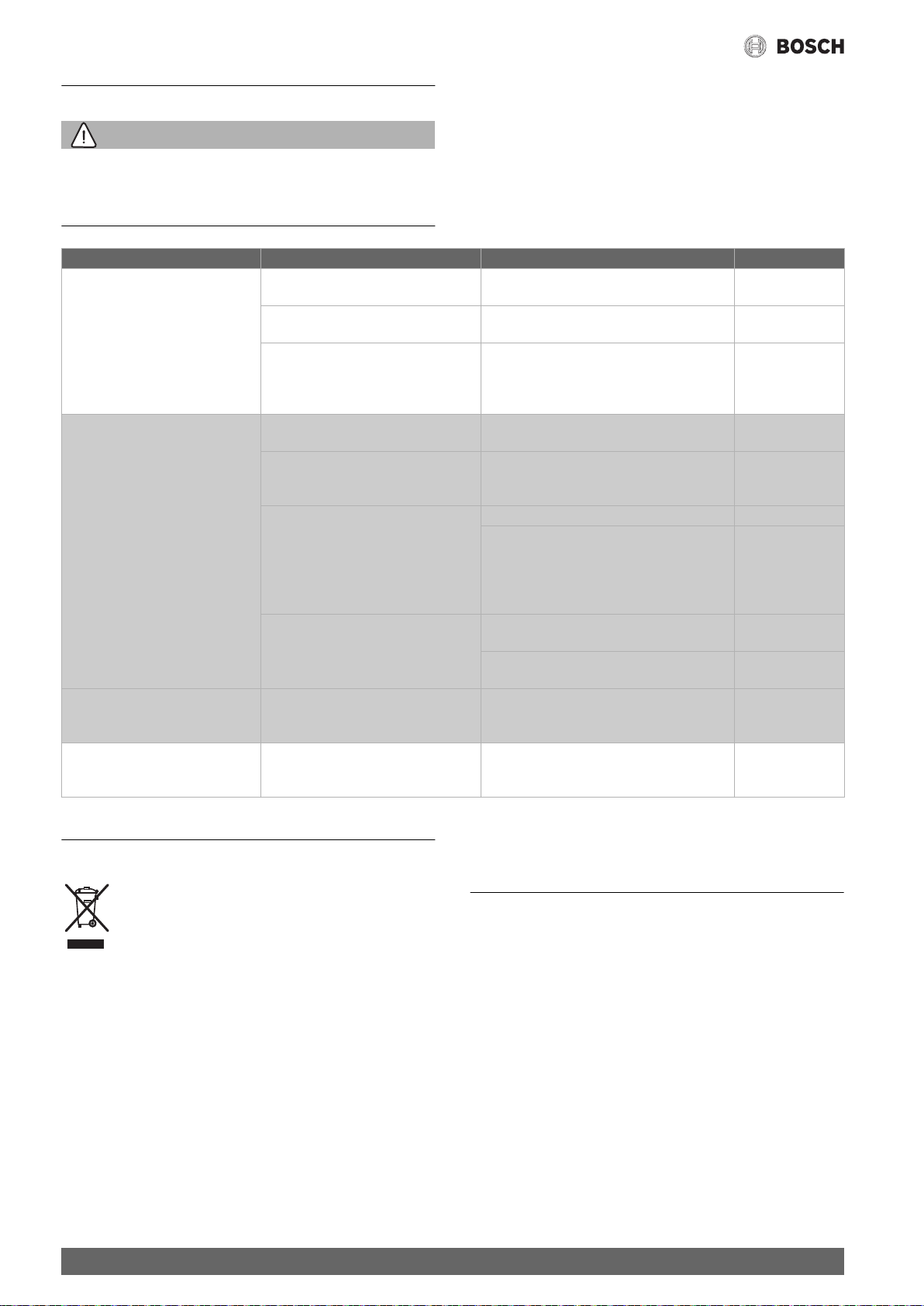
Co zrobić wprzypadku zakłócenia?
Jeżeli urządzenie nie działa zgodnie zoczekiwaniami, to często jest to
8 Co zrobić wprzypadku zakłócenia?
OSTRZEŻENIE:
Uwaga!
Naprawę urządzeń elektrycznych może przeprowadzić tylko iwyłącznie
wykwalifikowany specjalista. Niefachowo przeprowadzone naprawy
mogą wywołać poważne niebezpieczeństwa zagrażające użytkownikowi.
Usterka Przyczyna Środki zaradcze Kto
Przepływ wody jest zbyt mały.
Urządzenie nie włącza się.
Woda nie staje się wystarczająco
ciepła.
W czasie poboru wody podgrzewacz
przepływowy wyłącza się,
atemperatura wody spada.
Praca wzimie:
wzimie nie jest już osiągana
wymagana temperatura na wylocie.
Jeżeli usunięcie zakłócenia było niemożliwe, to należy wezwać serwis.
Zatkane sitko wzaworze wody lub
wgłowicy natryskowej.
Sitko w kątowym zaworze regulacyjnym
jest zatkane.
Kątowy zawór regulacyjny jest zatkany. Zawór ciepłej wody całkowicie otworzyć,
Zadziałał bezpiecznik instalacji
domowej.
Zadziałał bezpiecznik samoczynny
urządzenia.
Osiągnięta jest granica mocy. Za wysoki
przepływ lub za niska temperatura wody
zimnej na zasilaniu.
Drugi stopień pracy urządzenia nie
włącza się (brak słyszalnego
“kliknięcia”).
Uszczelka pęczniejąca w zaworze wody
ciepłej
Spadła temperatura zasilania. Na tyle zredukować strumień wody, pobieranej
spowodowane tylko jakąś drobnostką. Proszę sprawdzić, czy woparciu
oponiższe wskazówki nie jest możliwe samodzielne usunięcie
zakłócenia. Pozwoli to uniknąć kosztów niepotrzebnego wzywania
serwisu.
Wyjąć sitko ioczyścić go albo usunąć kamień. Klient
Zlecić specjaliście oczyszczenie sitka. Specjalista
Klient
a następnie kilkakrotnie otworzyć i zamknąć
kątowy zawór regulacyjny. Na zakończenie
wyczyścić sitko w zaworze wodnym
Sprawdzić bezpiecznik instalacji domowej. Klient
Zlecić specjaliście sprawdzenie bezpiecznika
samoczynnego urządzenia. Sprawdzić
dopuszczalną temperaturę zasilania.
Zredukować przepływ przy zaworze wodnym. Klient
Przez specjalistę:
zlecić regulację strumienia przepływu
na zaworze kątowym.
Sprawdzić ogranicznik przepływu lub
zamontować mniejszy
Sitko z zaworu wodnego wykręcić iwyczyścić
lub usunąć nagromadzony kamień.
Wyczyścić sitko w regulacyjnym zaworze
kątowym (Rys. A 4).
W zaworze wody ciepłej montować
niepęczniejące uszczelki.
zarmatury, aż osiągnięta zostanie wymagana
temperatura ciepłej wody.
Specjalista
Specjalista
Klient
Specjalista
Klient
Klient
9 Ekologiczna utylizacja
To urządzenie jest oznaczone zgodnie z Dyrektywą
Europejską 2012/19/UE oraz polską Ustawą z dnia
29 lipca 2005r. „O zużytym sprzęcie elektrycznym
ielektronicznym” (Dz.U. z 2005 r. Nr 180, poz. 1495)
symbolem przekreślonego kontenera na odpady.
Wytyczna ta określa ramy obowiązującego w całej Unii Euro
pejskiej odbioru i wtórnego wykorzystania starych
urządzeń.
Takie oznakowanie informuje, że sprzęt ten, po okresie jego użytkowania nie
może być umieszczany łącznie z innymi odpadami pochodzącymi
z gospodarstwa domowego. Użytkownik jest zobowiązany do oddania go
prowadzącym zbieranie zużytego sprzętu elektrycznego i elektronicznego.
Prowadzący zbieranie, w tym lokalne punkty zbiórki, sklepy oraz gminne
jednostka, tworzą odpowiedni system umożliwiający oddanie tego sprzętu.
Właściwe postępowanie ze zużytym sprzętem elektrycznym
ielektronicznym przyczynia się do uniknięcia szkodliwych dla zdrowia
ludzi i środowiska naturalnego konsekwencji, wynikających z obecności
26
składników niebezpiecznych oraz niewłaściwego składowania
i przetwarzania takiego sprzętu.
10 Gwarancja
Urządzenia obowiązują warunki gwarancji wydanej przez nasze
przedstawicielstwo handlowe w kraju zakupu.
Dokładne informacje otrzymacie Państwo w każdej chwili wpunkcie
handlowym, w którym dokonano zakupu urządzenia. W celu
skorzystania z usług gwarancyjnych konieczne jest przedłożenie dowodu
kupna urządzenia.
Zastrzega się prawo wprowadzania zmian.
Warunki gwarancji
Warunki gwarancji są regulowane odpowiednimi przepisami Kodeksu
Cywilnego oraz Rozporządzeniem Rady Ministrów zdn.30.05.1995 r.
„W sprawie szczególnych warunków zawierania i wykonywania umów
rzeczy ruchomych z udziałem konsumentów“.
Zmiany zastrzeżone.
TR2000 | TR2000R – 6 720 876 014 (2018/04)
Obsah 1 Bezpečnostní ustanovení
1 Bezpečnostní ustanovení . . . . . . . . . . . . . . . . . . . . . . . . . . . . .27
2 Návod pro montáž. . . . . . . . . . . . . . . . . . . . . . . . . . . . . . . . . . . .28
2.1 Montáž. . . . . . . . . . . . . . . . . . . . . . . . . . . . . . . . . . . . . . .28
3 Technické údaje . . . . . . . . . . . . . . . . . . . . . . . . . . . . . . . . . . . . .29
4 Zvláštní příslušenství. . . . . . . . . . . . . . . . . . . . . . . . . . . . . . . . .29
5 Návod k použití . . . . . . . . . . . . . . . . . . . . . . . . . . . . . . . . . . . . . .29
5.1 Seznámení s přístrojem . . . . . . . . . . . . . . . . . . . . . . . . .30
5.2 Obsluha přístroje . . . . . . . . . . . . . . . . . . . . . . . . . . . . . .30
5.2.1 Uvedení do provozu po zastavení vody . . . . . . . . . . . . .30
5.2.2 Šetření energie . . . . . . . . . . . . . . . . . . . . . . . . . . . . . . . .30
5.2.3 Zimní provoz . . . . . . . . . . . . . . . . . . . . . . . . . . . . . . . . . . 30
6 Čištění . . . . . . . . . . . . . . . . . . . . . . . . . . . . . . . . . . . . . . . . . . . . .30
7 Servisní služba . . . . . . . . . . . . . . . . . . . . . . . . . . . . . . . . . . . . . .30
8 Porucha, co dělat? . . . . . . . . . . . . . . . . . . . . . . . . . . . . . . . . . . . 31
9 Likvidace . . . . . . . . . . . . . . . . . . . . . . . . . . . . . . . . . . . . . . . . . . .31
10 Záruka . . . . . . . . . . . . . . . . . . . . . . . . . . . . . . . . . . . . . . . . . . . . .31
Tento spotřebič je určený pouze pro soukromé použití vdomácnosti.
• Montáž a obsluhu přístroje provádějte podle uvedeného textového
a obrazového popisu. Za škody vzniklé nedodržením pokynů tohoto
návodu neručíme.
• Tento přístroj je určen pro použití do výšky 2 000 m nad mořem.
• Přístroj instalujte a skladujte jen v prostoru chráněném před mrazem
(zbytková voda).
VAROVÁNĺ:
Nebezpečí úrazu elektrickým proudem!
V případě poruchy přístroj ihned odpojte od elektrické sítě.
V případě netěsnosti přístroje ihned uzavřete přívod studené vody.
• Průtokový ohřívač smí být připojen a do provozu uveden pouze
odborníkem.
• V zájmu bezpečnosti smí opravy a údržbu přístroje provádět jen
odborník.
• Přístroj, který není odpojený od přívodu elektrického proudu,
v žádném případě neotevírejte.
• Musí být dodrženy zákonné předpisy příslušné země, místních
elektrických rozvodných závodů a vodárenského podniku.
• Průtokový ohřívač je přístroj ochranné třídy I a musí být připojen
na ochranný vodič.
• Přístroj musí být trvale napojen na pevná vedení. Průřez vodičů
musí odpovídat instalovanému příkonu.
UPOZORNĚNĺ:
Pozor!
Uzemněná vodovodní potrubí mohou vytvářet dojem, že je připojen
ochranný vodič.
• K dodržení příslušných bezpečnostních předpisů musí být ze strany
instalace k dispozici všepólové odpojovací zařízení. Kontaktní otvor
musí mít nejméně 3 mm.
• Průtokový ohřívač je vhodný pouze pro uzavřený (tlakově stabilní)
provoz.
• Armatury musí být schválené pro provoz suzavřenými průtokovými
ohřívači (tlakově stabilními).
• Průtokový ohřívač připojte pouze na potrubí studené vody.
• Průtokový ohřívač je vhodný pro připojení na plastové trubky,
přezkoušené podle DVGW.
• Před montáží je nutno zbavit elektrický připojovací kabel napětí
a uzavřít přívod vody!
• Elektrickou přípojku je nutno dělat po zhotovení vodní přípojky.
• V zadní stěně udělejte pouze otvory, které jsou pro montáž nezbytné.
Při opětovné montáži musí být nepoužívané otvory vodotěsně
uzavřeny.
• Po montáži nesmí být možnost kontaktu sčástmi vedoucími napětí.
• Během prací na vodovodní síti odpojte přístroj od elektrické sítě.
Po dokončení prací postupujte jako při prvním uvedení do provozu.
• Na přístroji je zakázáno provádět jakékoli úpravy a změny.
• Přístroj je dovoleno používat jen k ohřevu pitné vody v domácnosti.
• Tento přístroj mohou používat děti od 8 let věku a osoby
s omezenými fyzickými, senzorickými nebo duševními schopnostmi
nebo s nedostatkem zkušeností a znalostí, pokud jsou pod dozorem
osoby zodpovědné za jejich bezpečnost, anebo od této osoby dostaly
pokyny, jak přístroj bezpečně používat, a chápou související
nebezpečí. Děti si s přístrojem nesmí hrát. Čištění a uživatelskou
údržbu nesmí provádět děti bez dohledu.
• Zabraňte dětem v přístupu k přístroji.
• Děti mějte pod dohledem, zabraňte, aby si s přístrojem hrály.

• Směšovací baterie a potrubí horké vody mohou být horké. Poučte
děti o této skutečnosti.
• Nepoužívejte abrazivní ani leptavé čisticí prostředky.
• Nepoužívejte parní čističe.
• Odvápnění přístroje smí provádět jen odborník.
Srdečně vám blahopřejeme k nákupu přístroje BOSCH. Vybrali jste si
vysoce kvalitní výrobek, který vám bude dělat dlouho radost.
Pozorně si prosím přečtěte návod pro montáž i návod k použití
a dodržujte v nich uvedené pokyny k zacházení a skladování!
2 Návod pro montáž
Průtokový ohřívač namontujte podle popisu v obrazové části. Dbejte
na poznámky v textu.
2.1 Montáž
Vybalení/sejmutí krytu (Obrázek 1)
• Přístroj vybalte a překontrolujte, zda nemá škody způso bené
přepravou.
• Obaly a popř. starý přístroj odstraňte v souladu s ochranou životního
prostředí.
Příprava pro montáž (Obrázek 2)
Dodatkové informace (Obrázek 6, A/B)
• Jestliže průtokový ohřívač nezapíná na plný výkon vlivem příliš
nízkého tlaku vody ve vaší domovní instalaci, odstraňte omezovač
průtoku (A, 3).
• Přednostní spínání při kombinaci s elektrickými akumulač ními
topnými tělesy (B).
Důležité! Používejte pouze přiloženou montážní sadu.
• Uzavřete přívod vody. Elektrická přípojka (připojovací kabel) musí
být bez napětí. Vyšroubujte nebo vypněte pojistky.
Montáž na stěnu (Obrázek 3)
• Průtokový ohřívač musí být na stěnu pevně namontován. Popřípadě
jej upevněte s pomocí spodních stavěcích šroubů.
• Vzdálenost od stěny je variabilní. Tak mohou být vyrovnány
nerovnosti stěny.
• Průchodka musí připojovací kabel těsně obepínat.
Jestliže se při montáži poškodí, musí být díry vodotěsně uzavřeny.
Vodní přípojka (Obrázek 4)
• Průtokový ohřívač je nutno odvzdušnit. K tomu je třeba otevřít
teplovodní kohout na maximum a přístroj 1 minutu proplachovat.
• Na přívod studené vody bezpodmínečně nainstalujte omezovač
průtoku.
Elektrická přípojka (Obrázek 5)
• Svorku přípojky na síť můžete namontovat nahoře nebo dole.
Opláštění přívodního kabelu musí být do zařízení zasunuto minimálně
v délce 40 mm.
Upozornění k instalaci
• Instalaci přístrojů, které nejsou osazeny síťovou zástrčkou, musí
provést příslušný provozovatel elektrické sítě nebo certifikovaná
odborná firma, která vám pomůže i se získáním souhlasu k instalaci
přístroje od příslušného provozovatele elektrické sítě.
Uvedení do provozu (Obrázek 6/7)
Přístroj splňuje požadavky normy IEC 61000-3-12.
• Překontrolujte, zda se při nízkém tlaku ve vodovodním potrubí zapne
stupeň 2 i při současném odběru na více kohoutkách se studenou
vodou. Jestliže tomu tak není, odstraňte omezovač průtoku
(viz Dodatková informace 6,A).
• Vysvětlete uživateli obsluhu průtokového ohřívače.
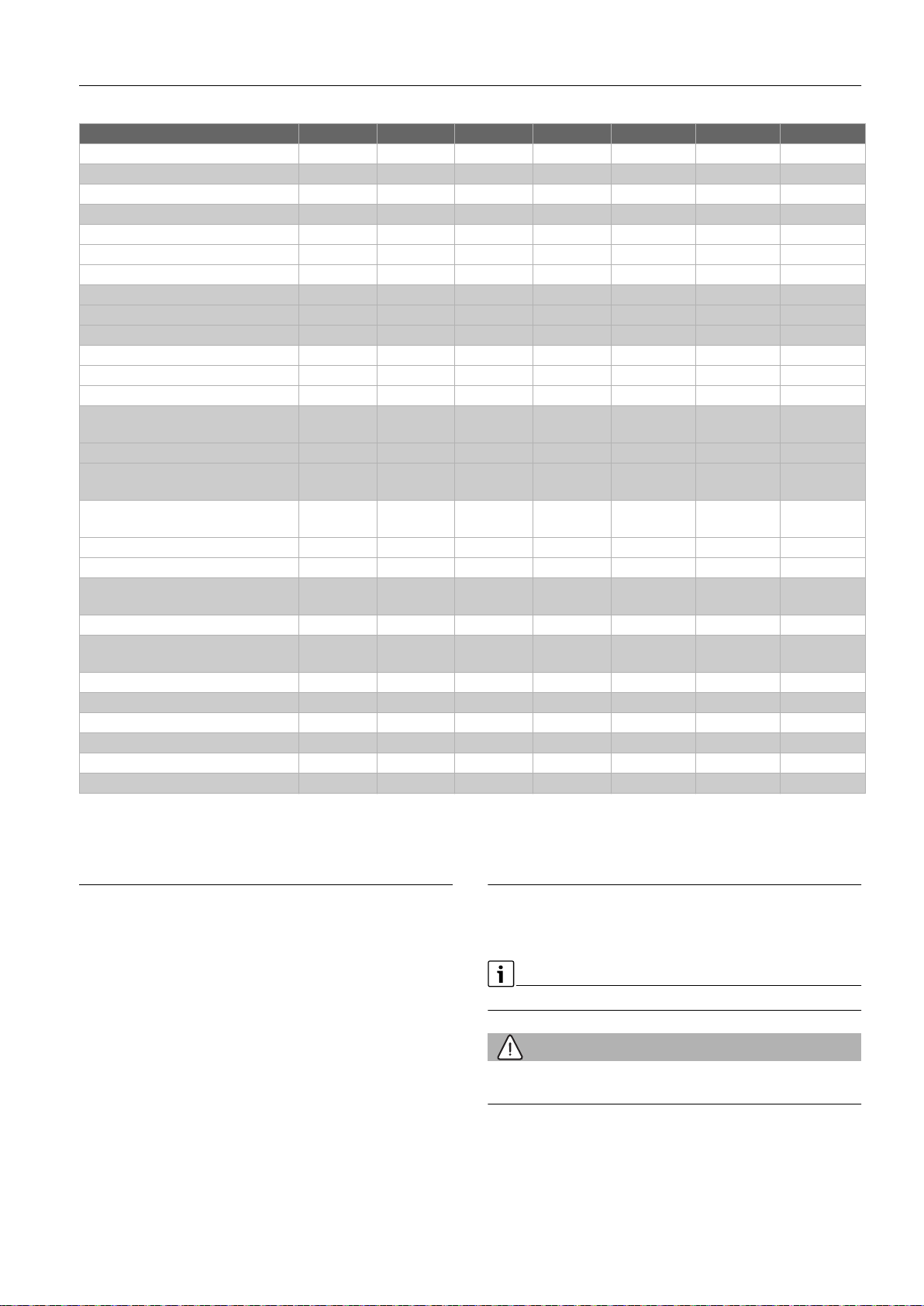
3 Technické údaje
TR2000 12 B TR2000 18 B TR2000 21 B TR2000 24 B TR2000R 18B TR2000R 21B TR2000R 24B
Jmenovitý výkon [kW] 13,2 18 21 24 18 21 24
Jmenovité napětí [V] 400V 3~ 400V 3~ 400V 3~ 400V 3~ 400V 3~ 400V 3~ 400V 3~
Jistič [A] 25 32 32 40 32 32 40
Minimální průřez vodiče [mm2] ** 2.5 4 4 6 6 4 6
Úsporná poloha e [kW]
1. stupeň – – – – 6 7 8
2. stupeň 8 12 14 16 12 14 16
Silný ohřev II [kW]
1. stupeň – – – – 9 10,5 12
2. stupeň 12 18 21 24 18 21 24
Zapínací bod [l/min]
1. stupeň – – – – 4,0 4,5 5,0
2. stupeň 3,6 5,0 5,8 6,6 5,0 5,8 6,6
Směšovaná voda [l/min]
při jmenovitém výkonu
ca. 38°C 6,6 9,9 11,6 13,2 9,9 11,6 13,2
ca. 50°C
(přívodní teplota 12°C)
Nejmenší průtočný tlak v přístroji*
[MPa (bar)]
s omezovačem průtoku 0,03 (0,3) 0,07 (0,7) 0,08 (0,8) 0,09 (0,9) 0,07 (0,7) 0,08 (0,8) 0,09 (0,9)
bez omezovače průtoku 0,02 (0,2) 0,04 (0,4) 0,05 (0,5) 0,06 (0,6) 0,04 (0,4) 0,05 (0,5) 0,06 (0,6)
Oblast nasazení ve vodách Specifický
elektrický odpor při 15°C [Ωcm]
Jmenovitý tlak [MPa (bar)] 1 (10) 1 (10) 1 (10) 1 (10) 1 (10) 1 (10) 1 (10)
Maximálně přípustná přívodní teplota
[°C]
Třída energetické účinnosti AAAA A A A
Zátěžový profil S S S S S S S
Roční spotřeba el. energie [kWh] 480 481 483 483 481 483 483
Denní spotřeba el. proudu [kWh] 2,213 2,215 2,228 2,232 2,215 2,228 2,232
Hladina akustického výkonu [dB] 15 15 15 15 15 15 15
Energetická účinnost ohřevu vody [%] 38,4 38,4 38,2 38,1 38,4 38,2 38,1
* K tomu ještě přijde pokles tlaku ve směšovací baterii
**V závislosti na konfiguraci připojení mohou být nutné větší průřezy kabelu
4,5 6,8 7,9 9,1 6,8 7,9 9,1
≥ 800 ≥ 1 300 ≥ 1 300 ≥ 1 300 ≥ 1 300 ≥ 1 300 ≥ 1 300
20 20 20 20 20 20 20
C Rozměry
4 Zvláštní příslušenství
• Prioritní spínač (relé náhlého odlehčení) BZ45L21:
pro režim s prioritním spínáním.
• Montážní sada BZ45K23: pro instalaci na omítku.
5 Návod k použití
Přečtěte si prosím podrobná bezpečnostní ustanovení na začátku
tohoto návodu a dodržujte v nich uvedené pokyny!
Důležité: Přístroj nikdy nevystavujte působení mrazu!
VAROVÁNĺ:
Nebezpečí úrazu elektrickým proudem!
V případě poruchy přístroj ihned odpojte od elektrické sítě.
• V případě netěsnosti přístroje ihned uzavřete přívod studené vody.
 Loading...