

Bosch Therm 6000 S Installation And Operating Instructions Manual
Installation and operating instructions
Gas Water Heater
Therm 6000 S
6 720 800 095 (2015/11) ZA
Read installation manual prior to installation of this unit!
Read user manual before putting this unit in operation!
Observe the warnings in the manuals!
The installation room must fulfill the ventilation requirements!
Installation by an authorised person only!

6 720 800 095 (2015/11) Therm 6000S
2 | Index
Index
1 Key to symbols and safety instructions . . . . . . . . . . 3
1.1 Key to symbols . . . . . . . . . . . . . . . . . . . . . . . 3
1.2 Safety information . . . . . . . . . . . . . . . . . . . . . 3
2 Technical Characteristics and Dimensions . . . . . . . 4
2.1 Declaration of conformity with relevant
EEC regulations . . . . . . . . . . . . . . . . . . . . . . .4
2.2 Explanation of Model Code . . . . . . . . . . . . . . 4
2.3 Package contents . . . . . . . . . . . . . . . . . . . . . 4
2.4 Description of the heater . . . . . . . . . . . . . . . 4
2.5 Optional accessories . . . . . . . . . . . . . . . . . . . 4
2.6 Dimensions . . . . . . . . . . . . . . . . . . . . . . . . . . 5
2.7 Appliance overview . . . . . . . . . . . . . . . . . . . . 6
2.8 Electrical diagram . . . . . . . . . . . . . . . . . . . . . 7
2.9 Technical data . . . . . . . . . . . . . . . . . . . . . . . . 8
2.10 Operational instructions . . . . . . . . . . . . . . . . 9
3 Regulation . . . . . . . . . . . . . . . . . . . . . . . . . . . . . . . . . . . 9
4 Operating instructions . . . . . . . . . . . . . . . . . . . . . . . . 9
4.1 Description LCD Display . . . . . . . . . . . . . . . 10
4.2 Before operating the appliance . . . . . . . . . 11
4.3 Connect and disconnect the appliance . . . 11
4.4 Water temperature setting . . . . . . . . . . . . . 11
4.5 Operation . . . . . . . . . . . . . . . . . . . . . . . . . . . 11
4.6 Registration of remote control
(accessory no 7 709 003 756) . . . . . . . . . 12
4.7 Remote control operation
(accessory no 7 709 003 756) . . . . . . . . . 12
4.8 Program button . . . . . . . . . . . . . . . . . . . . . . 13
4.9 "Priority" function . . . . . . . . . . . . . . . . . . . . 13
4.10 Purge the appliance . . . . . . . . . . . . . . . . . . 13
4.11 Reset button . . . . . . . . . . . . . . . . . . . . . . . . 14
4.12 Locked condition . . . . . . . . . . . . . . . . . . . . . 14
5 Installation instructions . . . . . . . . . . . . . . . . . . . . . . 14
5.1 Important remarks . . . . . . . . . . . . . . . . . . . 15
5.2 Selection of location for installation . . . . . . 15
5.3 Minimum distances . . . . . . . . . . . . . . . . . . . 15
5.4 Installation of fixing bracket . . . . . . . . . . . . 15
5.5 Installation . . . . . . . . . . . . . . . . . . . . . . . . . . 16
5.6 Water connection . . . . . . . . . . . . . . . . . . . . 17
5.7 Gas connection . . . . . . . . . . . . . . . . . . . . . . 17
5.8 Installation of the exhaustion accessory and
admission of air . . . . . . . . . . . . . . . . . . . . . 18
6 Admission / exhaustion accessories
(accessory Ø 80/80 mm) . . . . . . . . . . . . . . . . . . . . . .19
6.1 Admission/exhaustion accessories
(diameter in mm) . . . . . . . . . . . . . . . . . . . . .19
6.2 Fitting instructions . . . . . . . . . . . . . . . . . . . 20
6.3 Explanation of Symbols on Fitting
Diagrams . . . . . . . . . . . . . . . . . . . . . . . . . . . .20
6.4 Approved flue systems . . . . . . . . . . . . . . . . 21
7 Electrical connection . . . . . . . . . . . . . . . . . . . . . . . . 24
7.1 Connection . . . . . . . . . . . . . . . . . . . . . . . . . 24
7.2 Power cable . . . . . . . . . . . . . . . . . . . . . . . . . 24
7.3 Position of the fuses in control unit . . . . . . 24
8 Installation instructions . . . . . . . . . . . . . . . . . . . . . . 25
8.1 Factory regulations . . . . . . . . . . . . . . . . . . . 25
8.2 Measuring gas pressure . . . . . . . . . . . . . . . 25
8.3 Adjusting CO2 (carbon dioxide) . . . . . . . . 26
8.4 Program values . . . . . . . . . . . . . . . . . . . . . . 29
8.5 Control board diagnostics . . . . . . . . . . . . . 30
8.6 Fan speed adjustment . . . . . . . . . . . . . . . . 31
9 Maintenance . . . . . . . . . . . . . . . . . . . . . . . . . . . . . . . . 33
9.1 Periodic maintenance tasks . . . . . . . . . . . . 33
9.2 Verify the fuses in the control board . . . . . 33
9.3 Startup after maintenance . . . . . . . . . . . . . 34
10 Problem solving . . . . . . . . . . . . . . . . . . . . . . . . . . . . . 35
10.1 Problem/Cause/Solution . . . . . . . . . . . . . . 35
11 Functional scheme . . . . . . . . . . . . . . . . . . . . . . . . . . 39
12 Environmental protection . . . . . . . . . . . . . . . . . . . . 40
13 Warranty Terms . . . . . . . . . . . . . . . . . . . . . . . . . . . . . 41
6 720 800 095 (2015/11)Therm 6000S
Key to symbols and safety instructions | 3
1 Key to symbols and safety instructions
1.1 Key to symbols
Warnings
The following keywords are defined and can be used in this
document:
• NOTICE indicates a situation that could result in damage to
property or equipment.
• CAUTION indicates a situation that could result in minor to
medium injury.
• WARNING indicates a situation that could result in severe
injury or death.
• DANGER indicates a situation that will result in severe
injury or death.
Important information
Additional symbols
1.2 Safety information
If you smell gas:
▶ Close the gas valve.
▶ Open the windows.
▶ Do not operate any electrical appliances or switches (on/
off).
▶Extinguish any fire.
▶ Go to a different location and call the gas supplier or an
authorised technician.
If you smell combustion gases:
▶ Turn off the heater (page 11).
▶ Open doors and windows.
▶ Notify a gas fitter.
Installation, modifications
▶ The installation may only be carried out by registered
installers and shall comply with the requirements of SANS
10087-1.
▶The appliance must be installed along with
a low-pressure gas regulator.
▶ The assembly and modifications during the installation of
the heater can only be performed by an authorised
installer.
▶ Do not modify the pipes which conduct combustion gases.
▶ Do not close or reduce air circulation vents.
Maintenance
▶ We recommend to have the system regularly serviced in
order to ensure that it functions reliably and safely.
▶ The installer is responsible for the safety and
environmental compatibility of the installation.
▶ The heater must be serviced annually.
▶ Only original spare parts must be used.
Explosive and highly inflammable material
▶ Do not store or use inflammable material (paper, solvents,
paints, etc) near the heater.
Combustion air and surrounding air
▶ To avoid corrosion, the combustion air and surrounding air
must be free from harmful substances (e.g. halogenated
hydrocarbons which contain chlorine and fluorine
compounds).
Handover to the user
When handing over the heating system, instruct the user in its
operation and operating conditions.
▶ Explain the operation - with particular emphasis on all
safety-related actions.
▶ Explain that conversions and repairs must only be carried
out by an approved contractor.
▶ Point out the need for inspections and maintenance for
safe and environmentally-compatible operation.
▶ The installation and operating instructions must be given to
the user for keeping.
Warnings in this document are identified by
a warning triangle printed against a grey
background.
Keywords at the start of a warning indicate
the type and seriousness of the ensuing risk
if measures to prevent the risk are not taken.
This symbol indicates important information
where there is no risk to people or property.
Symbol Explanation
▶ Step in an action sequence
Cross-reference to another part of the document
• List entry
– List entry (second level)
Table 1

6 720 800 095 (2015/11) Therm 6000S
4 | Technical Characteristics and Dimensions
Safety of electrical appliances for
domestic use and similar purposes
The following requirements apply in
accordance with EN 60335-1 in order to
prevent hazards from occurring when using
electrical appliances:
“This appliance can be used by children of 8
years and older, as well as by people with
reduced physical, sensory or mental
capabilities or lacking in experience and
knowledge, if they are supervised and have
been given instruction in the safe use of the
appliance and understand the resulting
dangers. Children must not play with the
appliance. Cleaning and user maintenance
must not be performed by children without
supervision.”
“If the power cable is damaged, it must be
replaced by the manufacturer, its customer
service department or a similarly qualified
person, so that risks are avoided.”
2 Technical Characteristics and
Dimensions
2.1 Declaration of conformity with relevant EEC
regulations
This appliance fulfils European directive requirements
2009/142/EEC, 92/42/EEC, 2006/95/EEC, 2004/108/EEC
and corresponds to the specifications described in the
corresponding EEC certificate of proof.
2.2 Explanation of Model Code
[GWH] Gas water heater
[24] Capacity (Liter per minute)
[C] Room sealed box
[T] Thermostatic
[D] LCD
[E] Electric ignition
[23] Appliance adjusted for Natural Gas
[30] Appliance adjusted for LPG
2.3 Package contents
• Gas heater
• Support elements
• Heater documentation
2.4 Description of the heater
• Heater for wall-mounting
• High power pre-mix compact burner with low NOx
emissions
• Modulating Gas Valve with constant gas:air ratio control
• LCD panel with back light
• Failure codes for easy diagnostics and repair
• Electronic ignition
• Modulating water valve:
– Cold water temperature sensor
–Water flow sensor
• Hot water temperature sensor
• Built in frost protection
•Safety devices:
– Flame failure device (ionization flame rod sensor)
– Back flow temperature sensor
– Inlet temperature sensor
– Outlet temperature sensor
– Room sealed box temperature sensor
– Over heat prevention (temperature limiter)
• Power supply: 230 V, 50 Hz
• IP X4 (protection against water drops)
2.5 Optional accessories
• Gas conversion kit (NG)
– Code nº 7 719 002 460
• Freeze prevention kit
– Code nº 7 709 003 709
• Outdoor kit
Model GWH 24 CTD E
Category II
2H3B
Type C
Table 2
GWH 24 C TDE2330
Table 3
6 720 800 095 (2015/11)Therm 6000S
Technical Characteristics and Dimensions | 5
– Code nº 7 709 003 732
•Anti-freeze kit
– Code nº 7 709 003 709
•Cascading kit
– Code nº 7 736 500 272
• Wireless remote control to operate with the appliance
– Code nº 7 709 003 756
• High temperature kit
– Code nº 7 736 500 605
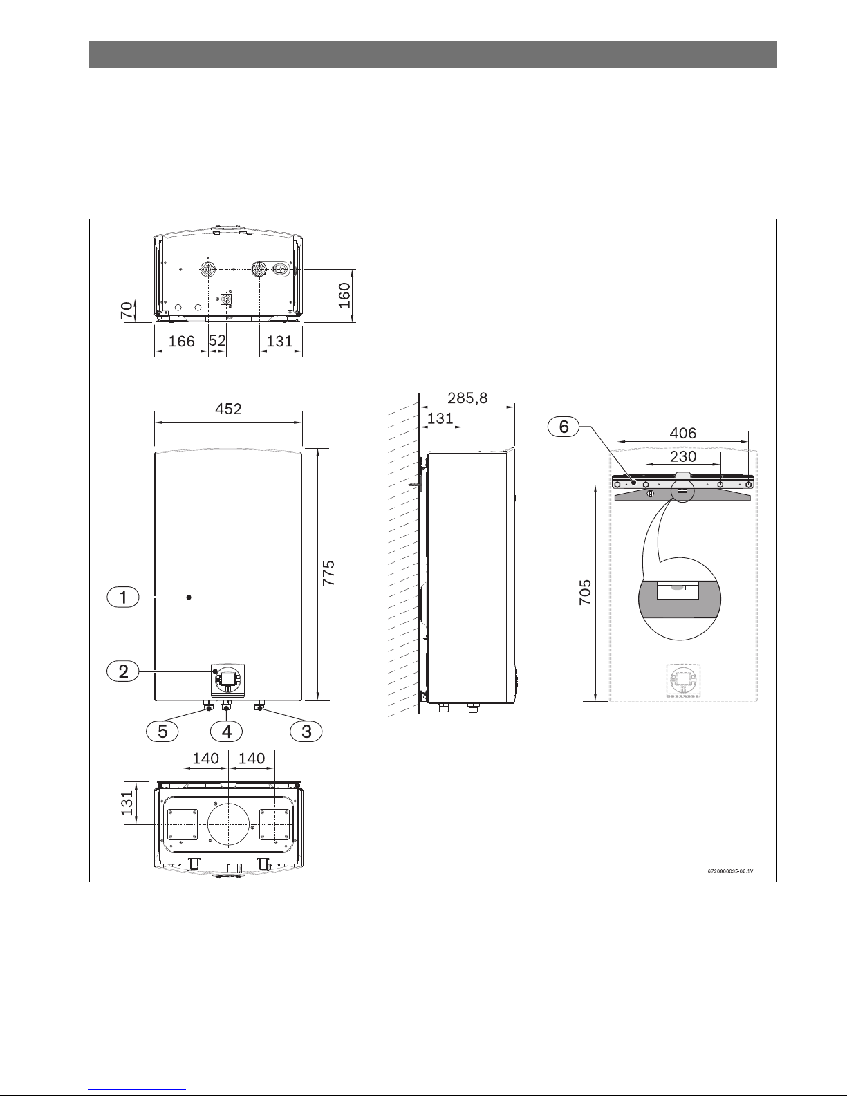
2.6 Dimensions
Fig. 1
[1] Front cover
[2] Key pad
[3] Cold water inlet: Ø ¾ “
[4] Gas connection: Ø ¾ “
[5] Hot water outlet: Ø ¾ “
[6] Support bracket
6 720 800 095 (2015/11) Therm 6000S
6 | Technical Characteristics and Dimensions
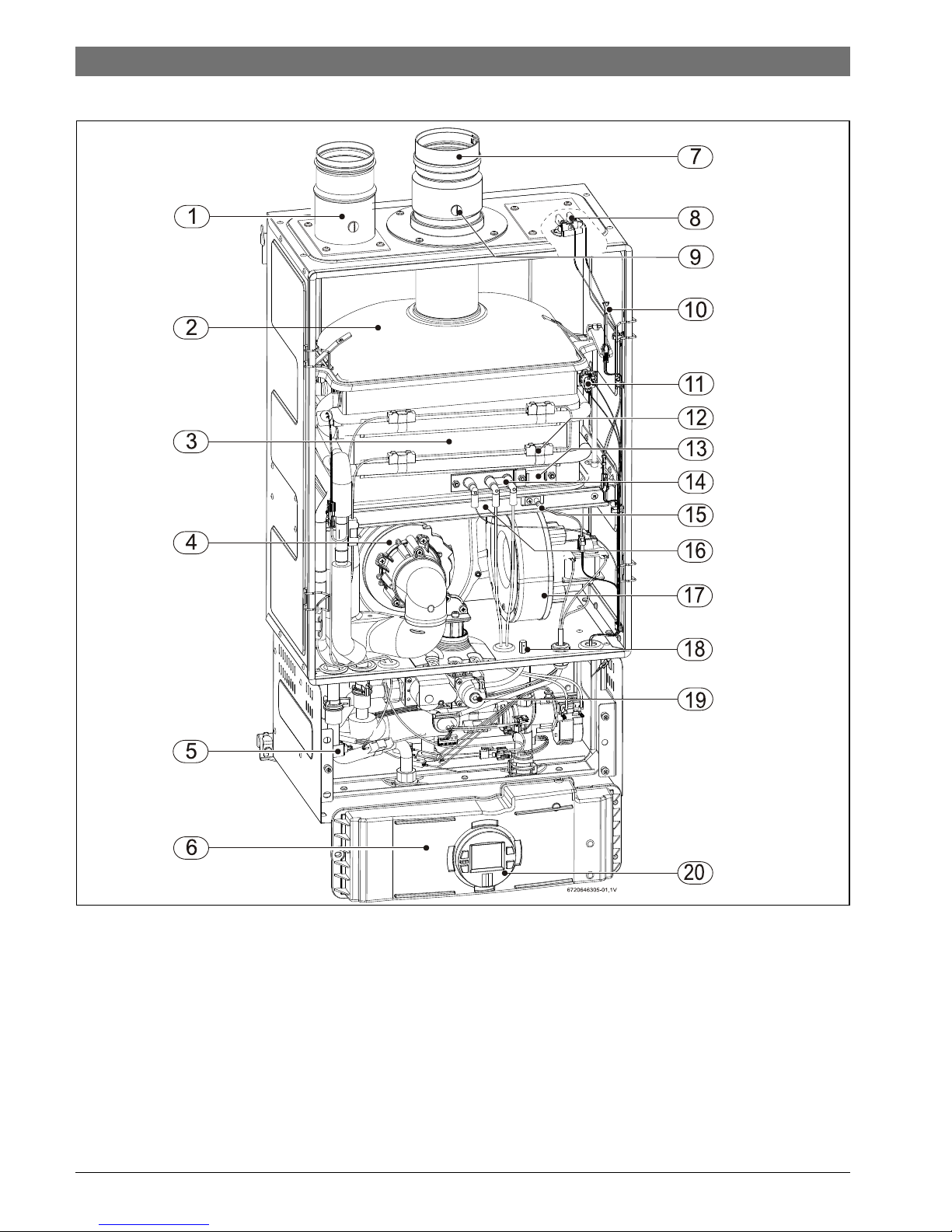
2.7 Appliance overview
Fig. 2
[1] Admission accessory (not included)
[2] Flue gas collector
[3] Heat exchanger
[4] Primary fan (Mixer)
[5] Hot water sensor
[6] Control unit
[7] Exhaust accessory (not included)
[8] Room sealed box temperature sensor
[9] CO
2
/ CO measuring point
[10] Exhaust temperature sensor
[11] Over heat prevention (temperature limiter)
[12] Anti-freeze heat element
[13] Observation window
[14] Ignition electrodes
[15] Backflow temperature sensor
[16] Ionization sensor
[17] Secondary air fan
[18] Pressure point gas valve
[19] Gas valve
[20] Key pad
6 720 800 095 (2015/11)Therm 6000S
Technical Characteristics and Dimensions | 7
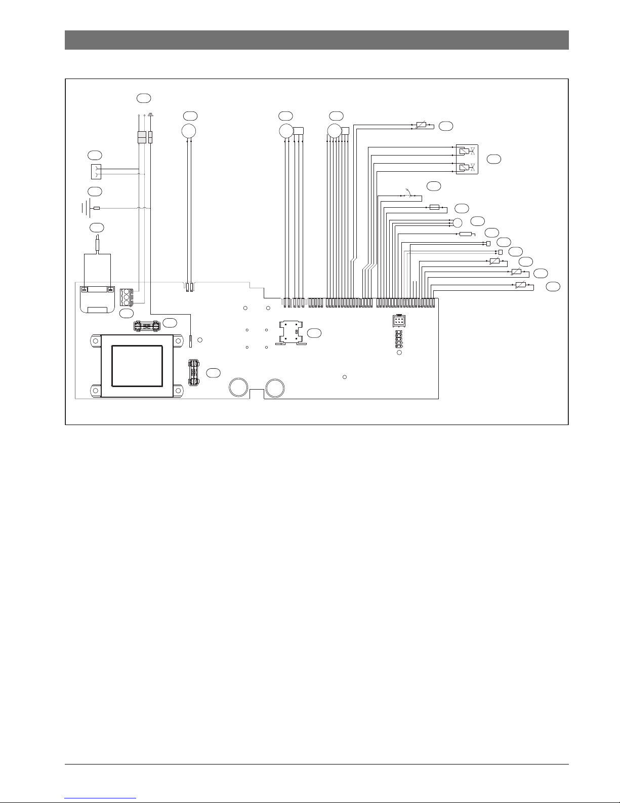
2.8 Electrical diagram
Fig. 3 Electrical scheme
[1] Intlet water temperature sensor
[2] Outlet water temperature sensor
[3] Backflow temperature sensor
[4] Cascading output connection
[5] Cascading input connection
[6] Ionization sensor
[7] Water flow sensor
[8] Room sealed box temperature sensor
[9] Heat exchanger overheat sensor (104 °C)
[10] Gas valve
[11] Resistance
[12] Water valve
[13] Primary fan
[14] ON/OFF switch
[15] Secondary fan
[16] AC plug
[17] Main connection
[19] Ground post
[20] Antifreeze kit connection
[21] Fuse
[22] Fuse
20 ... 120 ... 1
16 ... 116 ... 1
JP5
JP6
JP7
JP8
JP2
M
PS
M
M
E
FS
T=104°C
T=110°C
2
1
4
5
6
7
9
10
12
1315
16
20
19
18
21
22
17
14
8
3
6720608917-02.1AL
L N
11
T=90°C

6 720 800 095 (2015/11) Therm 6000S
8 | Technical Characteristics and Dimensions
2.9 Technical data
Technical characteristics Symbol Units GWH 24 CTDE
Power and flow
Nominal useful power Pn kW (Btu/h) 42,0 (143 310)
Minimum useful power Pmin kW (Btu/h) 6,0 (20 475)
Useful power (adjustment range) kW 6,0 - 42,0
Nominal thermal flow Qn kW (Btu/h) 48,4 (165 295)
Minimum thermal flow Qmin kW (Btu/h) 6,3 (21 500)
Gas data
Supply pressure
LPG (Butane) G30 kPa 3,0
Natural gas G20 kPa 2,0
Consumption
LPG (Butane) G30 kg/h 3,8
Natural gas G20 m3/h 5,1
Water data
Maximum permissible pressure pw bar 12
Minimum operating pressure pwmin bar 0,3
Minimum activation flow l/min 1,9
Maximum water flow with temperature rise of 25 °C l/min 24
Combustion products contents - DIN 4705
Exhaust gas flow
LPG - Butane kg/h 69,1
Temperature of gases at extractor grill
Exhaust temperature at maximum power °C 215
Exhaust temperature at minimum power °C 48
General Data
Voltage V230
Frequency Hz 50
Maximum power consumption W116
Type of protection IP X4D
Ambient temperature permitted °C 0 - 50
Noise db (A) 59
Efficiency %87
Weight (excluding packaging) kg 31
Table 4
6 720 800 095 (2015/11)Therm 6000S
Regulation | 9
2.10 Operational instructions
Hot water
Open the gas and water valves and ensure that all joints are
hermetic.
Place the principle switch (Fig. 4, [1]) in the operating position
(chapter 4.3), so that the appliance is quickly ready for use.
When a hot tap is opened, the water flow sensor should be in
(Fig. 2, [2]) send a signal to the control unit. This signal
initiates the following:
•The fan starts working
• Simultaneously, sparks are produced and the gas valve
opens.
•The burner lights.
• The ionisation electrode controls the state of the flame.
• The water temperature is controlled automatically by the
sensors/controllers according to the temperature
selected.
Security cut-off when safety period is surpassed
If a flame is not achieved within the stipulated security period
(35 sec), a security cut-off will occur.
The presence of air in the gas inlet pipe (when the appliance is
used after long periods of inactivity for example) may delay
ignition.
In this case, if the attempts to ignite go on too long, the security
mechanisms prevent operation.
Security cut-off due to excessive water heating
The control unit detects the heating temperature via a NTC
resistor located in the hot water exit tube and the temperature
limiter located in the heat exchanger. If it detects an excessive
temperature it provokes a security cut-off.
Restarting after security cut-off
To restart the appliance following a security cut-off:
▶ Press the reset key (Fig. 19).
3Regulation
Any local by-laws and regulations pertaining to installation and
use of gas-heated appliances must be observed. Please refer to
the laws that should be attended in your country.
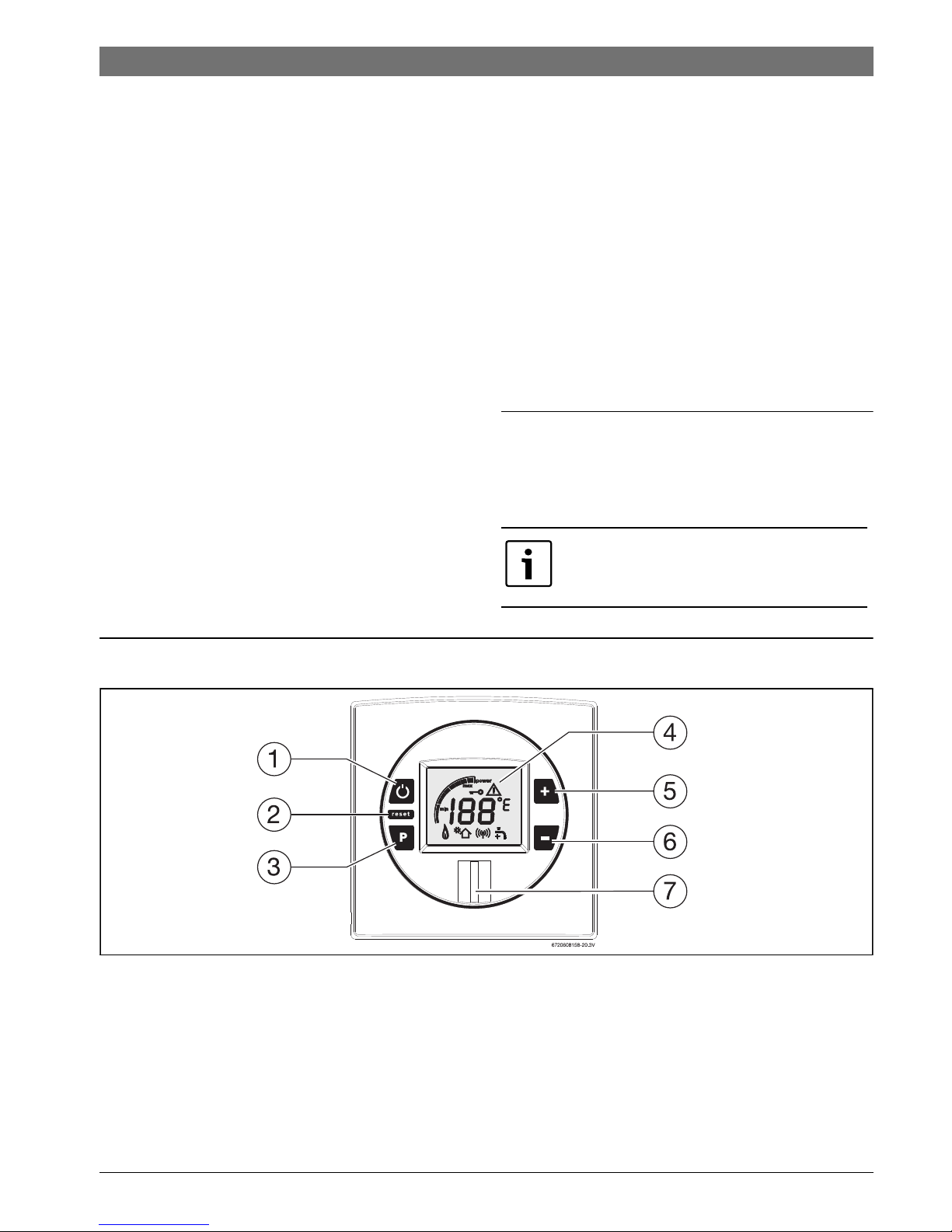
4 Operating instructions
Fig. 4
[1] Main switch ON/OFF
[2] Reset key
[3] Program key
[4] LCD panel
[5] Temperature increase key/ programming key
[6] Temperature decrease key / programming key
[7] LED
The installation may only be carried out by
registered installers and shall comply with
the requirements of SANS 10087-1.
6 720 800 095 (2015/11) Therm 6000S
10 | Operating instructions
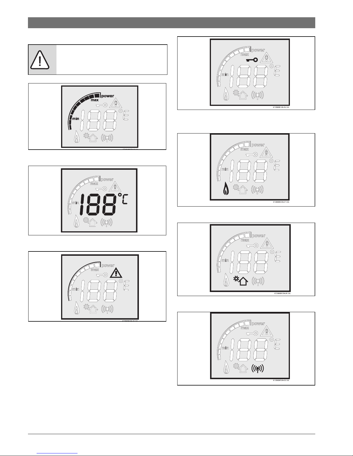
4.1 Description LCD Display
Fig. 5 Power bar indicator (input)
Fig. 6 Temperature indicator
Fig. 7 Error indicator
Fig. 8 Locked condition indicator (only with remote
control)
Fig. 9 Flame indicator
Fig. 10 Solar mode indicator
Fig. 11 Remote control indicator
CAUTION:
▶ Do not use any cleaning aggressive or
corrosive agents to clean the window.
6720608920-31.1AL
6 720 800 095 (2015/11)Therm 6000S
Operating instructions | 11
4.2 Before operating the appliance
▶ Confirm that the gas type of the heater matches the gas
supply you will be connecting the heater.
▶Open gas valve.
▶Open water valve.
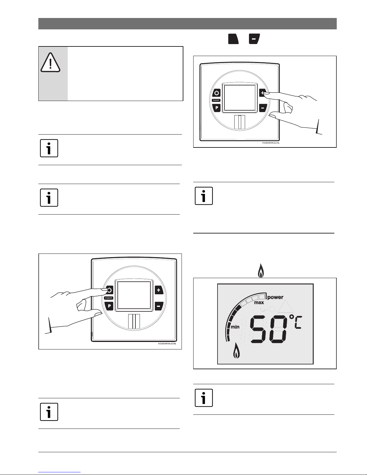
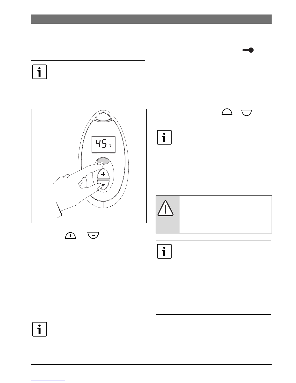
4.3 Connect and disconnect the appliance
Connect
▶ To start the appliance press the On/Off button.
Fig. 12
Disconnect
▶ To shut down the appliance press the On/Off button again.
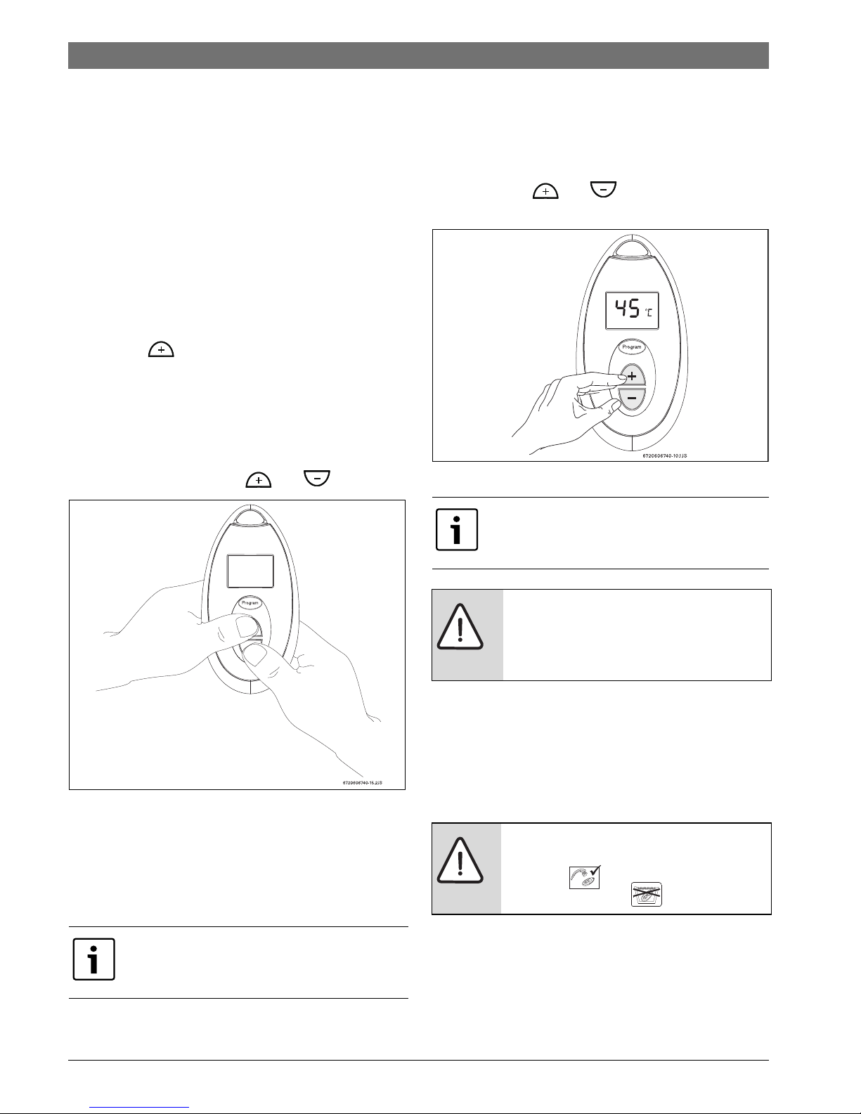
4.4 Water temperature setting
To regulate the emitted water temperature:
▶ Press the or until the desired value is
obtained.
Fig. 13
▶ Once the desired temperature is set, open the hot water
tap.
4.5 Operation
Turn ON the main switch and the appliance is ready to work.
▶ When a hot water tap is opened, main burner ignites and
LCD displays indication .
Fig. 14
CAUTION:
▶ The initial startup of the heater must be
realized by a qualified technician, who
will provide the client with all the
information necessary for its correct
usage.
Check for gas leaks at all joints.
Check for water leaks at all joints.
The temperature value indicated on the
LCD panel corresponds to the water
temperature at the appliance outlet.
These appliance has an electronically
controlled gas valve that modulates the
burner input in response to both varying hot
water flow rates and/or changes in any
incoming and outgoing water
temperatures.
LCD flashes until selected temperature is
reached.
+
6720608920-35.1AL
6 720 800 095 (2015/11) Therm 6000S
12 | Operating instructions
4.6 Registration of remote control (accessory no
7 709 003 756)
Only a qualified technician is allowed to install the additional
PCB that is supplied with the remote. Only after installation of
PCB the registration can be made.
The registration of the remote control must be done near the
appliance.
Hot water tap closed.
Turn OFF the appliance (Fig. 4, [1]).
▶ Press and hold the programming key (Fig. 4, [3]), press
ON/OFF button (Fig. 4, [1]) to connect the appliance.
Release programming key only when LCD displays “188”
The LCD displays the signal "P2".
▶ Press key , until it displays the signal "P3".
▶ Press programming key again for about 1 second.
LCD panel displays one number and one rotating digit.
The number represents the remote control which is to be
registered, the first remote control will be registered with
number “0”, the second with number “1” and so on.
▶ Test the remote control in front of the electronic box by
simultaneously pressing the and control keys.
Fig. 15 Activate new control
▶ Press both keys until the LCD panel stops flashing and
shows the indication “00”.
▶ Press ON/OFF button (Fig. 4, [1]) to disconnect the
appliance .
Remote control is now deactivated.
4.7 Remote control operation (accessory no 7
709 003 756)
This appliance fulfills European directive requirements 1999/
5/CEE (R&TTE) and corresponds to the specifications
described in the cor-responding CE certificate of proof.
▶ Press buttons and in order to reach r equested
temperature.
Fig. 16 Remote control (temperature selection)
Batteries replacement
▶ Remove the 2 screw from the remote control back.
▶Open the cover.
▶ Remove the old batteries and correctly place the new ones.
▶ Close the remote control assuring that both screws are
tighten screwed.
Precautions when using the batteries
• Do not dispose of batteries as domestic waste. Take them
to appropriate collecting places for recycling.
• Do not insert flat batteries.
• Only use the type of batteries indicated.
Press the ON/OFF button to turn ON the
remote control and it’s ready to work.
NOTE: up to 6 remote controls can be
programmed for one single water heater,
each with a range distance of 30m.
CAUTION:
▶ Remote control is not a toy - do not allow
children to play with the remote control
unit.
CAUTION:
▶ remote control can be used under the
shower , however, it’s immersion
must not be forced .
6 720 800 095 (2015/11)Therm 6000S
Operating instructions | 13
4.8 Program button
Program button can be used/programmed in the appliance and
in the remote control.
Programming "Program" function
Fig. 17 "Program" key
▶ Press buttons and to select temperature to
be memorized.
▶ Press "Program" button for 3 seconds to save temperature.
The temperature is saved on "Program" when the LCD
panel stops blinking.
Using "Program" function
In order to select memorized temperature:
▶ Press "Program" key.
LCD shows pre-memorized temperature, which is now the
selected hot water temperature.
4.9 "Priority" function
The appliance does not have a designated default priority.
Priority is attributed when the first user selects a temperature
(see chapter 4.4).
The following symbol appears for other users .
The priority user may change the initial selection at any time.
Non-priority users cannot change the selection made by the
priority user.
The system resets priority function 5 minutes after last water
demand, returning to the initial state.
To select priority
Any user may select temperature selection priority in the
following manner:
▶ Press one of the selection keys or for
5seconds.
4.10 Purge the appliance
If there is a risk of freezing, proceed as follows:
▶ Close the cold water valve of the water heater.
▶ Open hot water taps to drain the water heater.
▶ Remove all the water contained inside of the appliance.
Each remote control program button can
be programmed with different temperature
values according with the user needs. A
temperature value can be programmed in
the remote control and another value in the
appliance.
PRIORITY is a function to prevents the user
from accidentally altering the water
temperature selected by another user.
Program
6720608920-32.1AL
Priority cannot be selected when the
appliance is working.
CAUTION:
▶ The non accomplishment of the
purgative of the appliance whenever the
freezing risk exists, it can damage
components of the appliance.
The internal frost protection is designed to
provide protection for the water heater
down to approximately -10 °C for short term
conditions only. It will not protect the
appliance in areas where the temperature is
frequently expected to be below freezing.
The frost protection will not protect the
installation outside the appliance from
freezing. Suitable measures should be taken
to protect the installation against frost
damage.
6 720 800 095 (2015/11) Therm 6000S
14 | Installation instructions
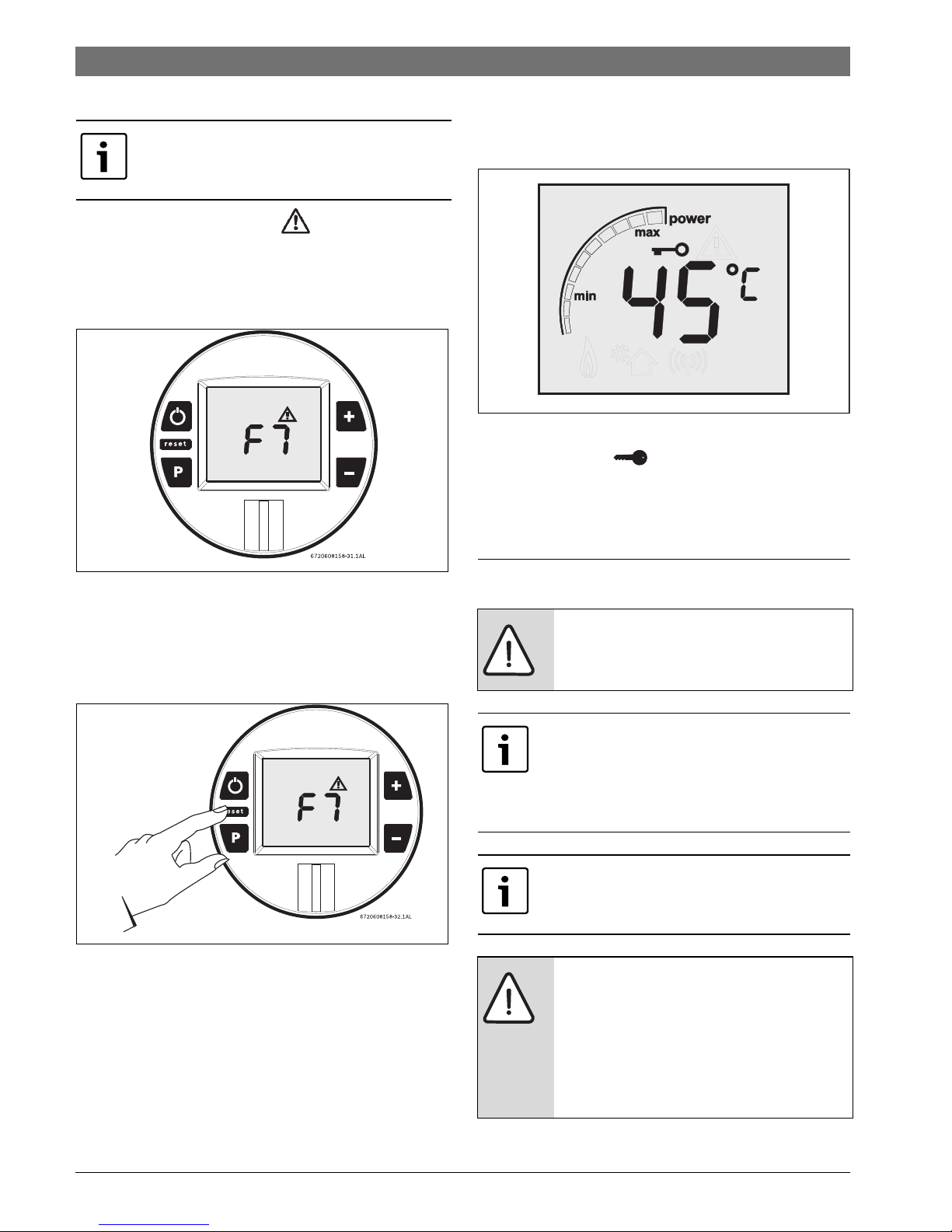
4.11 Reset button
If the LCD shows the error symbol do not shut off power
or unplug the heater. Follow instructions below to reset error
first.
Record the error code on LCD and consult chapter 10 to
identify the error.
Fig. 18 Error code
After following instructions indicated in “Troubleshooting”
section,
▶ press reset button firmly in order to return heater to normal
operation.
Fig. 19 Reset button
If the problem persists, contact your installer.
4.12 Locked condition
This condition is only valid for appliances with one or more
remote controls installed.
Fig. 20 Locked condition
Whenever LCD shows the temperature setting cannot
be adjusted because the appliance is in use by a user which
already selected a different temperature. Appliance will be
automatically unlock 5 minutes after closing hot water tap.
5 Installation instructions
This appliance has a error codes system. The
visualization of these codes is made through
the LCD display. (Fig. 4, [4]).
DANGER: Explosion!
▶ Always close the gas valve before doing
any work in gas components.
The installation, the electric connection, the
gas installation, the installation of the
exhaustion / admission conducts, as well as
the start up must be carried out by a qualified
technician.
The appliance can only be used in the
countries mentioned in the type plate.
CAUTION:
▶ Do not install the appliance where the
inlet water temperature is superior to
60 °C. In such cases we recommended
the installation of a mixer's valve in the
entrance of the appliance as prevention
measure.
6720608920-33.1AL
 Loading...