

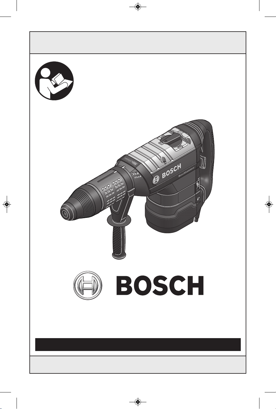
Bosch RH1255VC Operating/safety Instructions Manual
IMPORTANT: IMPORTANT : IMPORTANTE:
Read Before Using Lire avant usage Leer antes de usar
For English Version Version française Versión en español
See page 2 Voir page 12 Ver la página 22
Operating/Safety Instructions
Consignes de fonctionnement/sécurité
Instrucciones de funcionamiento y seguridad
1-877-BOSCH99 (1-877-267-2499) www.boschtools.com
Call Toll Free for
Consumer Information
& Service Locations
Pour obtenir des informations
et les adresses de nos centres
de service après-vente,
appelez ce numéro gratuit
Llame gratis para
obtener información
para el consumidor y
ubicaciones de servicio
RH1255VC
160992A1RU.qxp_RH1255VC 8/27/15 10:22 AM Page 1
-2-
Work area safety
Keep work area clean and well lit. Cluttered
or dark areas invite accidents.
Do not operate power tools in explosive
atmospheres, such as in the presence of
flammable liquids, gases or dust. Power
tools create sparks which may ignite the dust
or fumes.
Keep children and bystanders away while
operating a power tool. Distractions can
cause you to lose control.
Electrical safety
Power tool plugs must match the outlet.
Never modify the plug in any way. Do not
us e any ada p t e r plugs w i th eart h e d
(grounded) power tools. Unmodified plugs
an d ma tchin g ou tlets wil l re duce risk o f
electric shock.
Avoid body contact with earthed or grounded
surfaces such as pipes, radiators, ranges
and refrigerators. There is an increased risk
of electric shock if your body is earthed or
grounded.
Do not expose power tools to rain or wet
conditions. Water entering a power tool will
increase the risk of electric shock.
Do not abuse the cord. Never use the cord
for carrying, pulling or unplugging the power
tool. Keep cord away from heat, oil, sharp
edges or moving parts. Damaged or entangled
cords increase the risk of electric shock.
When operating a power tool outdoors,
use an extension cord suitable for outdoor
use. Use of a cord suitable for outdoor use
reduces the risk of electric shock.
If operating a power tool in a damp location
is unavoidable, use a Ground Fault Circuit
Interrupter (GFCI) protected supply. Use of
an GFCI reduces the risk of electric shock.
Personal safety
Stay alert, watch what you are doing and
us e c ommon se nse when o pera ting a
power tool. Do not use a power tool while
you are tired or under the influence of drugs,
alcohol or medication. A moment of inattention
while operating power tools may result in
serious personal injury.
Use personal protective equipment. Always
wear eye protection. Protective equipment
such as dust mask, non-skid safety shoes, hard
hat, or hearing protection used for appropriate
conditions will reduce personal injuries.
Prevent unintentional starting. Ensure the
sw itch is in the off- posi tion be fore
connecting to power source and / or battery
pa ck, pi cking u p o r c arry ing the to ol.
Carrying power tools with your finger on the
switch or energizing power tools that have the
switch on invites accidents.
Remove any adjusting key or wrench before
turning the power tool on. A wrench or a
key left attached to a rotating part of the
power tool may result in personal injury.
Do not overreach. Keep proper footing and
balance at all times. This enables better
co ntrol of the p ower tool in une x pected
situations.
Dress properly. Do not wear loose clothing
or jewelry. Keep your hair, clothing and
gloves away from moving parts. Loose
clothes, jewelry or long hair can be caught in
moving parts.
If devices are provided for the connection
of dust extraction and collection facilities,
ensure these are connected and properly
used. Use of dust collection can reduce dust-
related hazards.
Power tool use and care
Do not forc e the pow e r too l . Use the
correct power tool for your application. The
correct power tool will do the job better and
safer at the rate for which it was designed.
Do not use the power tool if the switch does
not turn it on and off. Any power tool that
ca n n ot be cont r o l led with the swit c h is
dangerous and must be repaired.
Read all safety warnings and all instructions. Failure to follow the warnings
and instructions may result in electric shock, fire and/or serious injury.
SAVE ALL WARNINGS AND INSTRUCTIONS FOR FUTURE REFERENCE
The term “power tool” in the warnings refers to your mains-operated (corded) power tool or
battery-operated (cordless) power tool.
!
WARNING
General Power Tool Safety Warnings
160992A1RU.qxp_RH1255VC 8/27/15 10:22 AM Page 2

-3-
Rotary Hammer Safety Rules
Wear ear protectors. Exposure to noise can
cause hearing loss.
Use auxiliary handle(s), if supplied with the
tool. Loss of control can cause personal injury.
Hold power tools by insulated gripping
surfaces, when performing an operation
where the cutting tool may contact hidden
wiring or its own cord. Cutting accessory
contacting a "live" wire may make exposed
metal parts of the power tool "live" and could
give the operator an electric shock.
Use clamps or another practical way to
secure and support the workpiece to a
stable platform. Holding the work by hand
or against your body leaves it unstable and
may lead to loss of control.
Do not drill, fasten or break into existing
walls or other blind areas where electrical
wiring ma y ex is t. If this si t u a ti on is
unavoidable, disconnect all fuses or circuit
breakers feeding this worksite.
Use a metal detector to determine if there
are gas or water pipes hidden in the work
area or call the local utility company for
assistance before be g i nn ing th e
operation. Striking or cutting into a gas line
will result in explosion. Water entering an
electrical device may cause electrocution.
Always use the side handle for maximum
control over torque reaction or kick-back.
Never attempt to operate this tool with
one hand. The slip clutch engages if you
firmly control the tool during a torque reaction
or kickback.
Always wear safet y g o g g l e s o r e y e
protection when using this tool. Use a
dust mask or respirator for applications
that generate dust. Safety goggles or eye
protection will help deflect fragments of the
material that may be thrown toward your face
and eyes. Dust generated or gases released
from the material yo u ar e cu t t i n g (i.e.
asbestos insulated pipes, radon) may cause
respiratory difficulties.
Use thick cushioned gloves and limit the
expo sure t ime by taking frequent rest
periods. Vibration caused by hammer-drill
action may be harmful to your hands and
arms.
Position the cord clear of rotating bit. Do
not wrap the cord around your arm or
wrist. If cord becomes entangled with the
spinni ng b it it could e ntrap you cau sing
serious personal injury.
Position yourself to avoid being caught
between the tool or side handle and walls
Disconnect the plug from the power source
a
nd/or the battery pack from the power tool
before making any adjustments, changing
accessories, or storing power tools. Such
preventive safety measures reduce the risk of
starting the power tool accidentally.
Store idle power tools out of the reach of
children and do not allow persons unfamiliar
with the power tool or these instructions to
operate the power tool. Power tools are
dangerous in the hands of untrained users.
Maintain power tools. Check for misalignment
or binding of moving parts, breakage of
parts and any other condition that may
affect the power tool’s operation. If damaged,
have the power tool repaired before use.
Ma n y a c c idents are caused by poor l y
maintained power tools.
Keep cutting tools sharp and clean. Properly
m
aintained cutting tools with sharp cutting
edges are less likely to bind and are easier to
control.
Use the power tool, accessories and tool
bits etc. in accordance with these instructions,
taking into account the working conditions
and the work to be performed. Use of the
power tool for operations different from those
intended could result in a hazardous situation.
Service
Have your power tool serviced by a qualified
re p a i r pe r s o n us i n g onl y iden t i c a l
replacement parts. This will ensure that the
safety of the power tool is maintained.
160992A1RU.qxp_RH1255VC 8/27/15 10:22 AM Page 3

or posts. Should the bit become bound or
j
ammed in the work, the reaction torque of
the tool could crush your hand or leg.
Do not str ike t he bi t wit h a h andhe l d
hammer o r s l e d g e h ammer w h e n
attempting to d islodge a b o u n d or
jammed bit. Fragments of metal from the bit
could dislodge and strike you or bystanders.
Never place the tool down until the bit or
accessory has come to a complete stop.
Do not u se du l l or dam a ged b i t s an d
a
ccessories. Dull or damaged bits have a
greater tendency to bind in the workpiece.
When removing the bit from the tool avoid
contact w i t h sk in and u s e proper
protective gloves when grasping the bit or
accessory. Accessories may be hot after
prolonged use.
Do not run the tool while carrying it at
your side. A spinning bit could become
entangled with clothing and injury may result.
-4-
Additional Safety Warnings
GFCI and personal protection devices like
electrician’s rubber gloves and footwear will
further enhance your personal safety.
Do not use AC only rated tools with a DC
power supply. While the tool may appear to
work, the electrical components of the AC
rated tool are likely to fail and create a hazard
to the operator.
Keep handles dry, clean and free from oil
and grease. Slippery hands cannot safely
control the power tool.
Develop a periodic maintenance schedule
for your tool. When cleaning a t ool be
careful not to disassemble any portion of
th e tool sin ce inte rnal wi res may be
misplaced or pinched or safety guard return
sp ring s may be impro perl y mou nted .
Certain cleaning agents such as gasoline,
carb on te trachloride, ammonia, etc. may
damage plastic parts.
Risk of injury to user. The power cord must only
be serviced by a Bosch Factory Service Center
or Autho rized Bosch Service Station.
Some dust created by power
sanding, sawing, grinding,
drilling, and other construction activities
contains chemicals known to cause cancer,
birth defects or other reproductive harm.
Some examples of these chemicals are:
• Lead from lead-based paints,
• Crystalline silica from bricks and cement and
other masonry products, and
• Arsenic and chromium from chemically-
treated lumber.
Yo u r risk from the s e exposu r e s vari e s ,
depending on how often you do this type of
work. To r educe your e xposure to t hese
chemicals: work in a well ventilated area, and
work with approved safety equipment, such as
those dust masks that are specially designed
to filter out microscopic particles.
!
WARNING
160992A1RU.qxp_RH1255VC 8/27/15 10:22 AM Page 4
-5-
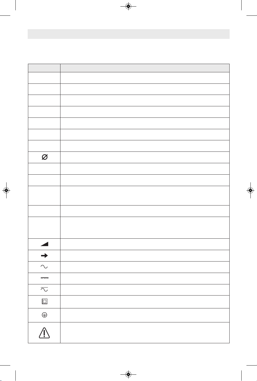
Symbols
IMPORTANT: Some of the following symbols may be used on your tool. Please study them
and learn their meaning. Proper interpretation of these symbols will allow you to operate the
tool better and safer.
Symbol Designation / Explanation
V Volts (voltage)
A Amperes (current)
Hz Hertz (frequency, cycles per second)
W Watt (power)
kg Kilograms (weight)
min Minutes (time)
s Seconds (time)
Diameter (size of drill bits, grinding wheels, etc.)
n
0
No load speed (rotational speed at no load)
n Rated speed (maximum attainable speed)
.../min
Revolutions or reciprocation per minute (revolutions, strokes, surface speed,
orbits etc. per minute)
0 Off position (zero speed, zero torque...)
1, 2, 3, ...
I, II, III,
Selector settings (speed, torque or position settings. Higher number means
greater speed)
0
Infinitely variable selector with off (speed is increasing from 0 setting)
Arrow (action in the direction of arrow)
Alternating current (type or a characteristic of current)
Direct current (type or a characteristic of current)
Alternating or direct current (type or a characteristic of current)
Class II construction (designates double insulated construction tools)
Earthing terminal (grounding terminal)
Warning symbol (alerts user to warning messages)
160992A1RU.qxp_RH1255VC 8/27/15 10:22 AM Page 5
-6-
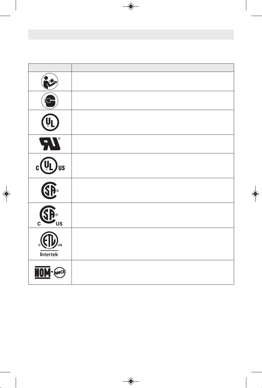
Symbols (continued)
Conforms to
UL Standard 60745-1
UL Standard 60745-2-6
Certified to
CAN/CSA Standard C22.2 No. 60745-1
CAN/CSA Standard C22.2 No. 60745-2-6
IMPORTANT: Some of the following symbols may be used on your tool. Please study them
and learn their meaning. Proper interpretation of these symbols will allow you to operate the
tool better and safer.
Symbol Designation / Explanation
Alerts user to read manual
Alerts user to wear eye protection
This symbol designates that this tool is listed by Underwriters Laboratories.
This symbol designates that this component is recognized by Underwriters
Laboratories.
This symbol designates that this tool is listed by Underwriters Laboratories,
to United States and Canadian Standards.
This symbol designates that this tool is listed by the Canadian Standards
Association.
This symbol designates that this tool is listed by the Canadian Standards
Association, to United States and Canadian Standards.
This symbol designates that this tool is listed by the Intertek Testing
Services, to United States and Canadian Standards.
This symbol designates that this tool complies to NOM Mexican Standards.
160992A1RU.qxp_RH1255VC 8/27/15 10:23 AM Page 6
-7-
Model number RH1255VC
Shank style SDS Max
Maximum Capacities:
Carbide tipped bits 2"
Thin wall core bits 6"
Functional Description and Specifications
Di s c onnect the plu g from the pow e r sour c e befor e makin g any
assembly, adjustments or changing accessories. Such preventive safety
measures reduce the risk of starting the tool accidentally.
!
WARNING
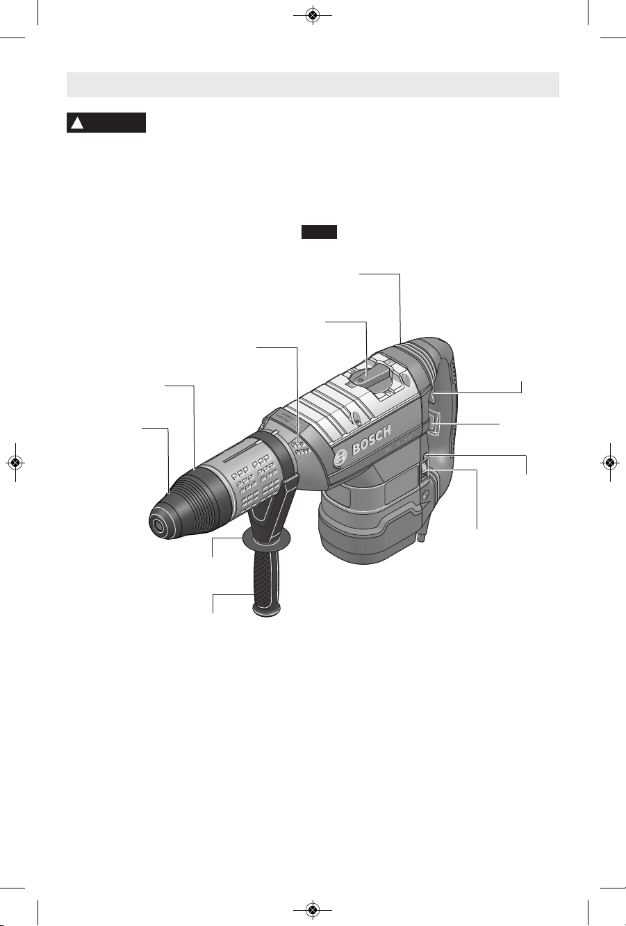
Rotary Hammer
NOTE: For tool specifications refer to the nameplate on your tool.
FIG. 1
LOCKING SLEEVE
DUST SHIELD
VENTILATION OPENINGS
AUXILIARY
HANDLE
HAND GRIP
VARIABLE
SPEED DIAL
SERVICE
REMINDER
LIGHT
SELECTOR LEVER
TRIGGER
RELEASE
SWITCH
TRIGGER
SWITCH
VIBRATION DAMPER
HANDLE / HAMMER MECHANISM
160992A1RU.qxp_RH1255VC 8/27/15 10:23 AM Page 7
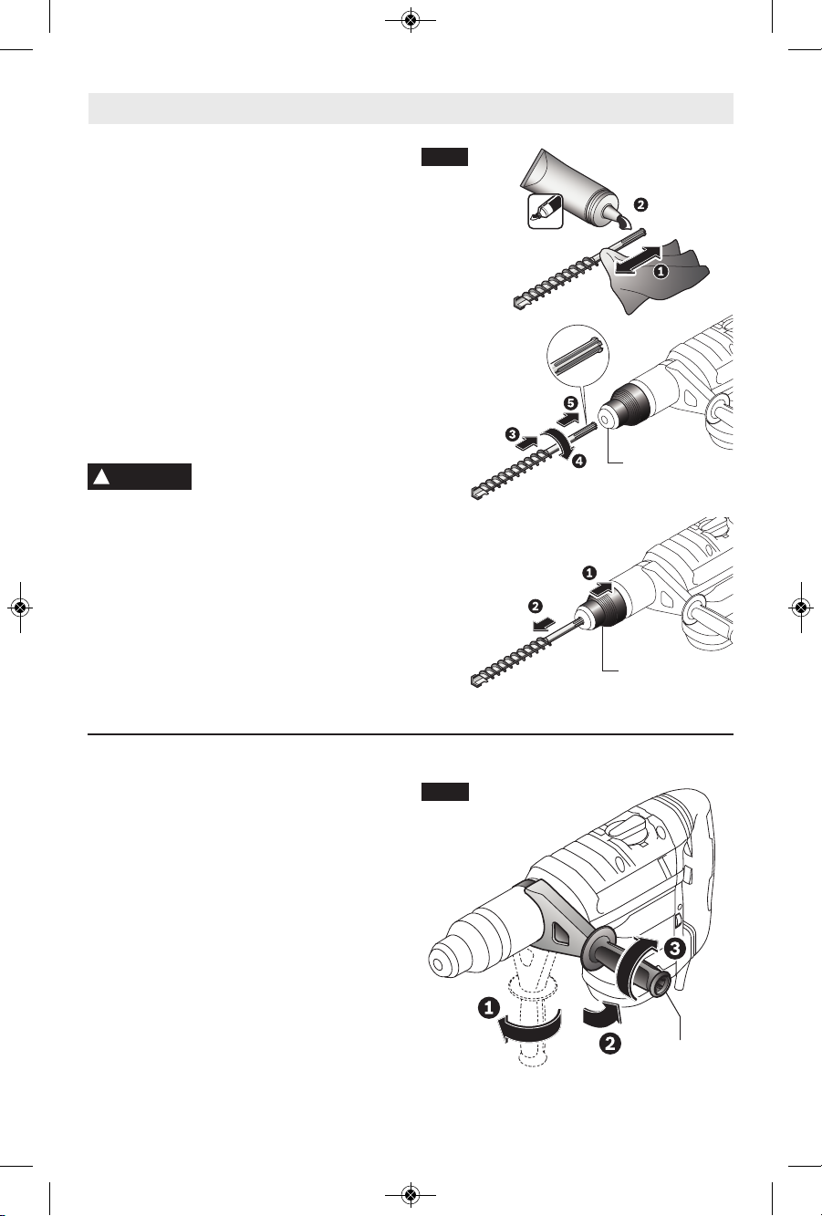
INSTALLING ACCESSORIES
Clean the insert shank end of the accessory
t
o remove any debris, then lightly grease with
a light oil or lubricant.
Insert accessory into the tool holder through
the dust shield, while twisting and pushing
inward until it locks automatically into place.
Pull outward on the accessory to be certain it
is locked into the tool holder (Fig. 2).
NOTE: The high efficiency available from
the rotary hammers can only be obtained if
sharp and undamaged accessories are used.
The "cost" to maintain sharp and undamaged
accessories is more than offset by the "time
sa v e d " in o p e rating t h e tool w i t h sharp
accessories.
REMOVING ACCESSORIES
Accessories may be hot after
use. Avoid contact with skin
and use proper protective gloves or cloth to
remove.
To remov e an a c cessory , pull and hol d
locking sleeve backward and pull bit forward
(Fig. 2). All accessories should be wiped
clean after removing.
-8-
Assembly
LOCKING SLEEVE
DUST SHIELD
FIG. 2
!
WARNING
AUXILIARY HANDLE
The tool must be supported with the auxiliary
handl e, whic h can b e swive led 360˚. To
reposition and/or swivel the handle, loosen
the hand grip, move the handle to the
desired position al o n g t h e b a r r e l a n d
securely retighten the hand grip (Fig. 3).
HAND GRIP
FIG. 3
160992A1RU.qxp_RH1255VC 8/27/15 10:23 AM Page 8
-9-
Operating Instructions
DUAL FUNCTION TRIGGER SWITCH
To turn t h e tool “ O N ” in th e D r illing/
Hammering mode, squeeze and hold the
trigger switch. To turn the tool “OFF”, release
the trigger switch, which is spring loaded and
will return to the “OFF” position automatically
(Fig. 1).
Your tool is also equipped with a "Lock-ON"
fe a t u r e when the sele c t o r dial i s in t h e
Ha m m e r i n g On l y m o d e wh i c h al l o w s
continuous operation without holding the
trigger (Fig. 1).
TO LOCK TOOL “ON”: turn the selector dial
to the Hammering Only mode and squeeze
the trigger switch until it locks.
TO TURN TOOL: “OFF“ press the trigger
release switch and the trigger will return to
the “OFF” position automatically.
To increase switch life, do not turn switch on
and off while tool is under load.
VARIABLE SPEED DIAL
Your tool is equipped with a variable speed
dial (Fig. 1). The impact rate (BPM) and
rotating sp e e d (RP M ) can be varie d
according to th e type of wo rk being
performed by setting the variable speed dial
to the selected setting. The chart below will
help you to determine which setting to use
for your application. However, a pre-test will
determine the best speed setting, as the
chart is intended only as a guide. Once the
proper setting is determined the impact rate
and rotating s p e e d is k e p t constant by
means of the "Electronic Feedback Circuitry".
The variable speed dial can be adjusted
while the mo tor i s ru nnin g, allowi ng the
operator to adjust the impact rate and
rotating speed accord i n g to the actual
application.
"TURBO" FEATURE
In th e "Hammer Only" mo d e powe r is
automatically increased 20% when the tool is
turned on t o provide maximum chiselin g
performance.
ELECTRONIC FEEDBACK CIRCUITRY
(EFC)
The i nternal electr onic fe edback system
provides a "soft start", which will reduce the
stresses that occur from a high torque start.
Th e sy stem also he lps to ke ep the pr eselec ted impac t rate and rotating spee d
virtually constant between no-load and load
conditions.
Chipping (Demolition)
Area of application Control setting
Plaster work 1 - 2
Removing tiles 3
Brick work 4
Concrete 5 - 6
Drilling Holes
Lower speeds Higher speeds
Accurate starts Faster penetration
Minimize breakouts
when the bit exits
the material.
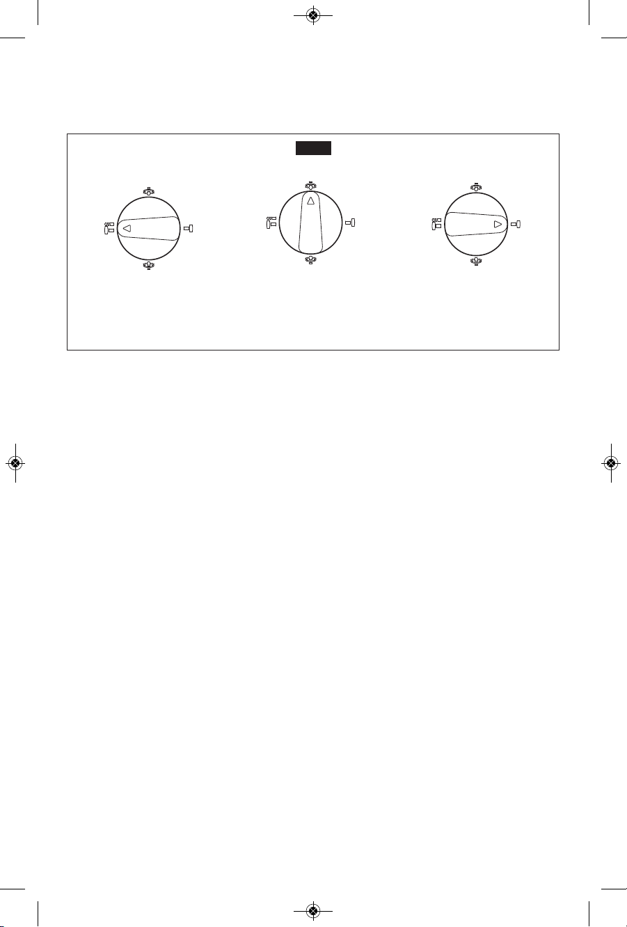
SELECTOR LEVER
The selector lever allows the tool to be set
fo r vari o u s app l ication s as l i sted i n the
following chart, (Fig. 4).
Do not operate the selection
dial until the tool comes to a
complete stop. Shifting during rotation of the
chuck can cause damage to the tool.
When using demolition or chipping bits such
as bull points, chisels, spades, gouges, etc.
the “Hammer Only” mode must be selected.
SELECTOR LEVER - “VARIO-LOCK”
The vario-lock can be set in any one of twelve
positions (30˚ increments). Choose a position
which is best suited for your operation. The
Vario-Lock position is intended for use with
chipping bits such as bull points, spades,
gouges, etc.
!
CAUTION
160992A1RU.qxp_RH1255VC 8/27/15 10:23 AM Page 9
Turn the selector lever, to the “vario-lock”
s
etting . Nex t, ro tate the loc king sleeve,
along with the accessory, to the desired
position. Then turn the selector lever to the
“hammer only” setting and slightly turn the
l
ocking sleeve to have it automatically lock
into a definite position.
-10-
Drilling/Hammering:
used for drilling with solid
carbide bits and core bits
Hammering Only:
used for chipping
and demolition work
Vario-Lock:
allows chisel to be set in
one of 12 positions
(right or left “0” position)
F
I
G.
4
VIBRATION DAMPER HANDLE /
HAMMER MECHANISM
The integrated vibration damper in the main
handle and hammer mechanism reduces
vibrations (Fig. 1).
SLIP CLUTCH
The tool has a internal pre-set slip clutch. The
output spindle will stop rotating if the accessory
binds and overloads the tool.
TOOL TIPS
Following a few simple tips will reduce wear
on the tool and the chance of injury to the
operator.
The high efficiency available from the BOSCH
Rotary Hammer can only be obtained if sharp
and undamaged drilling tools are used. Note
that the costs for maintaining sharp drilling
tools are more than offset by the time lost in
operating dull drilling tools.
All grease packed hammers require a short
ti m e to warm up. Depending o n t h e
te m p erature, this ti m e will vary fr o m
ap p r oximatel y 15 second s (90° F) to 2
minutes (32° F). The tool will exert its full
power and hammering action after the heat
from impact hammering has spread, softening
the grease.
CARBIDE TIPPED BITS
Used for drilling stone, concrete, cement,
brick, cinder block and other unusually hard
non-metals. The Rotary Hammer is designed
for “SDS” Carbide Tipped Bits up to 3/4 inch
diameter.
DRILLING MASONRY
Use carbide-tipped SDS-plus
®
bit for cinder
block, mortar, common brick, soft stone and
other materials. The amount of pressure to be
used is dependent upon the type of material
being drilled. Soft materials require less
pressure while the hard materials need more
pressure to prevent the drill bit from spinning.
160992A1RU.qxp_RH1255VC 8/27/15 10:23 AM Page 10
 Loading...