

BOSCH PSR 14,4 VE-2, PSR 9,6 VE-2 User Manual
2 609 932 287 - Buch Seite 1 Mittwoch, 22. Oktober 2003 1:58 13
Bedienungsanleitung
Operating instructions
Instructions d’emploi
Instrucciones de servicio
Manual de instruções
Istruzioni d’uso
Gebruiksaanwijzing
Betjeningsvejledning
Bruksanvisning
Brukerveiledningen
Käyttöohje
Οδηγία χειρισµού
Kullan∂m k∂lavuzu
PSR 9,6 VE-2
PSR 12 VE-2
PSR 14,4 VE-2
* Des idées en action.
PSR 18 VE-2
Deutsch
English
Français
Español
Português
Italiano
Nederlands
Dansk
Svenska
Norsk
Suomi
Eλληvικά
Türkçe
2 609 932 287 - Buch Seite 1 Mittwoch, 22. Oktober 2003 1:58 13
10
1
2
3
9
4
5
6
PSR 9,6 VE-2
PSR 12 VE-2
PSR 14,4 VE-2
PSR 18 VE-2
A
6
8
7
B
2 • 2 609 932 287 • 03.10
12 11
13
2 609 932 287 - Buch Seite 1 Mittwoch, 22. Oktober 2003 1:58 13
C
14
E
➊➋
D
14
F
➌ ➍ ➎
G
➏
➐
3 • 2 609 932 287 • 03.10
H
➒ ➓
➑
2
3
4
5
6
7
8
9
*
■
■
■
■
2 609 932 287 - Buch Seite 1 Mittwoch, 22. Oktober 2003 1:58 13
Gerätekennwerte
Akku-Bohrschrauber PSR 9,6 VE-2 PSR 12 VE-2 PSR 14,4 VE-2 PSR 18 VE-2
Bestellnummer 0 603 943 6.. 0 603 943 5.. 0 603 943 4.. 0 603 943 3..
Leerlaufdrehzahl
1. Gang [min
2. Gang [min
Drehmomenteinstellbereich [Nm] 0,7 –9,0 0,7 –9,0 0,7– 9,0 0,7 – 9,0
max. Drehmoment harter/
weicher Schraubfall nach
ISO 5393
max. Bohr-Ø (1./2. Gang)
Stahl [mm] 10/8 10/10 10/10 12/12
Holz [mm] 18/16 20/19 28/20 30/ 22
Schrauben-Ø, max. [mm] 6 6 7 8
Bohrfutterspannbereich [mm] 1–10 1–10 1–10 1–10
Bohrspindelgewinde 3/8" 3/8" 3/8" 3/8"
Gewicht ohne Akku, ca. [kg] 1,0 1,0 1,0 1,2
Akku
Temperaturüberwachung NTC NTC NTC NTC
Nennspannung [V=] 9,6 12 14,4 18
Kapazität [Ah] 1,5 1,5 1,5 1,5
Gewicht, ca. [kg] 0,5 0,6 0,75 1,0
Bitte die Bestellnummer Ihrer Maschine beachten. Die Handelsbezeichnungen einzelner Maschinen können variieren.
-1
] 0 – 390 0 – 390 0 – 400 0 – 400
-1
] 0 – 1 250 0–1 250 0–1 250 0 – 1 250
[Nm] 22/8 24/12 30/16 42/22
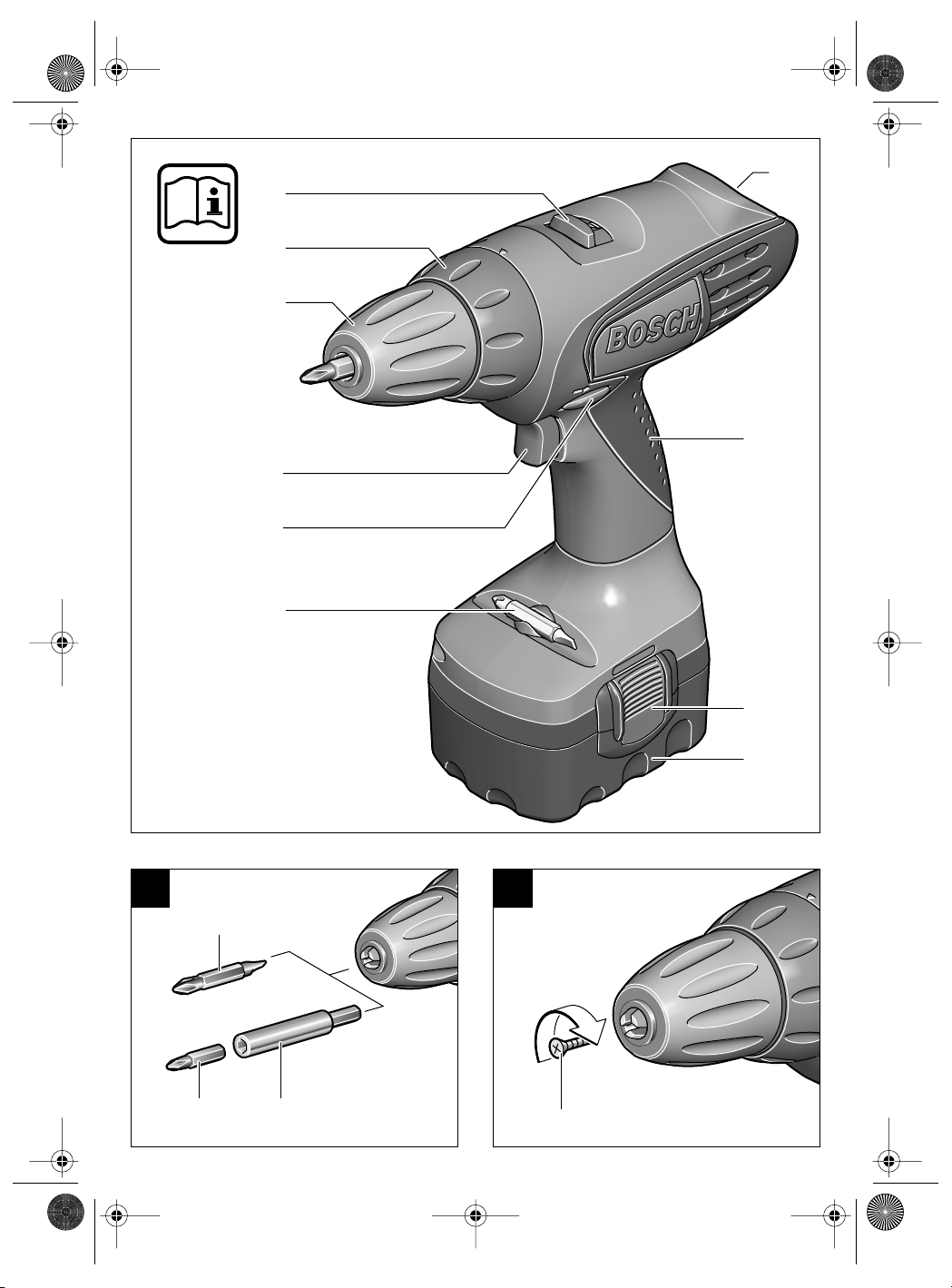
Geräteelemente
1 Gangwahlschalter
Drehmoment-Einstellring
Schnellspannbohrfutter
Ein-/Ausschalter
Drehrichtungsumschalter
Schrauberklinge*
Akku*
Akku-Entriegelungstaste
Softgrip
10 Akku-Schrauber Display
11 Schraubendrehereinsatz (Bit)*
12 Universalbithalter*
13 Sicherungsschraube
14 Innensechskantschlüssel*
Abgebildetes oder beschriebenes Zubehör gehört
teilweise nicht zum Lieferumfang.
Bestimmungsgemäßer Gebrauch
Das Gerät ist bestimmt zum Eindrehen und Lösen von Schrauben sowie zum Bohren in Holz,
Metall, Keramik und Kunststoff.
4 • 2 609 932 287 • 03.10
Deutsch - 1
Zu Ihrer Sicherheit
Gefahrloses Arbeiten mit dem
Gerät ist nur möglich, wenn Sie
die Bedienungsanleitung und
die Sicherheitshinweise vollständig lesen und die darin ent-
folgen. Zusätzlich müssen die allgemeinen
Sicherheitshinweise im beigefügten Heft befolgt werden.
Schutzbrille tragen.
Bei langen Haaren Haarschutz tragen. Nur mit
eng anliegender Kleidung arbeiten.
Vor jeder Benutzung Gerät und Akku überprü-
fen. Werden Schäden festgestellt, Gerät nicht
weiter benutzen. Reparatur nur von einem
Fachmann durchführen lassen. Gerät nie
selbst öffnen.
Vor allen Arbeiten am Gerät (z. B. Wartung,
Werkzeugwechsel, usw.) sowie bei dessen
Transport und Aufbewahrung den Drehrichtungsumschalter stets in Mittelstellung
bringen.
unbeabsichtigtem Betätigen des Ein-/Ausschalters.
haltenen Anweisungen strikt be-
Sonst besteht Verletzungsgefahr bei
A
■
■
■
2 609 932 287 - Buch Seite 2 Mittwoch, 22. Oktober 2003 1:58 13
■
■
■
■
■
■
■
7
8
■
3
3
7
4
4
4
4
■ Überzeugen Sie sich vor der Benutzung vom
sicheren Sitz des Akkus im Gerät.
Verwenden Sie geeignete Suchgeräte, um
verborgene Versorgungsleitungen aufzuspüren, oder ziehen Sie die örtliche Versorgungsgesellschaft hinzu.
Kontakt mit Elektroleitungen kann zu Feuer
und elektrischem Schlag führen.
Beschädigung einer Gasleitung kann zur Explosion führen. Eindringen in eine Wasserleitung verursacht Sachbeschädigung.
Gerät gut festhalten: Beim Festziehen können
kurzzeitig hohe Reaktionsmomente auftreten.
Sichern Sie das Werkstück. Ein mit Spann-
vorrichtungen oder Schraubstock festgehaltenes Werkstück ist sicherer gehalten als mit Ihrer Hand.
Niemals Kindern die Benutzung des Gerätes
gestatten.
Bosch kann nur dann eine einwandfreie Funktion des Gerätes zusichern, wenn das für dieses Gerät vorgesehene Original-Zubehör verwendet wird.
Akku und Ladegerät
Unbedingt die beiliegende Bedienungsanleitung des Ladegerätes lesen!
Akku nicht öffnen sowie vor Stoß schützen.
Trocken und frostsicher aufbewahren.
Erwärmten Akku vor dem Laden abkühlen lassen.
Akku vor Hitze und Feuer schützen: Explosionsgefahr! Akku nicht auf Heizkörper ablegen
oder längere Zeit starker Sonneneinstrahlung
aussetzen, Temperaturen über 50 °C schaden.
Den Akku nicht in den Hausmüll, ins Feuer
oder ins Wasser werfen.
Vor der Inbetriebnahme
Akku laden
Ein neuer oder längere Zeit nicht verwendeter
Akku bringt erst nach ca. 5 Lade- und Entladezyklen seine volle Leistung.
Zur Entnahme des Akkus
drücken und den Akku nach unten heraus-
ten
ziehen. Keine Gewalt anwenden.
Der Akku ist mit einer NTC-Temperaturüberwachung ausgestattet, welche Ladung nur im Temperaturbereich zwischen 0 °C und 45 °C zulässt.
Dadurch wird eine hohe Akku-Lebensdauer erreicht.
die Entriegelungstas-
Eine wesentlich verkürzte Betriebszeit nach der
Aufladung zeigt an, dass die Akkus verbraucht
sind und ersetzt werden müssen.
Hinweise zum Umweltschutz beachten.
Werkzeugwechsel
Das Bohrfutter
Werkzeug eingesetzt werden kann. Das Werkzeug einsetzen.
Die Hülse des Schnellspannbohrfutters
Hand kräftig zudrehen. Das Bohrfutter wird dadurch automatisch verriegelt.
Drehen Sie die Hülse in Gegenrichtung um das
Werkzeug zu entnehmen.
durch Drehen öffnen, bis das
von
Schrauben (siehe Bild )
Die Schrauberklinge 6 direkt in das Bohrfutter
einspannen oder bei Verwendung von Schraubendrehereinsätzen (Bits)
versalbithalter
12 verwenden.
11 zusätzlichen Uni-
Inbetriebnahme
Akku einsetzen
Den Drehrichtungsumschalter 5 auf Mitte = Einschaltsperre stellen und den geladenen Akku
den Griff einrasten lassen.
in
Ein-/Ausschalten
Zur Inbetriebnahme des Gerätes den Ein-/Ausschalter
Zum
schalter
drücken und gedrückt halten.
Die Maschine läuft je nach Druck
auf den Ein-/Ausschalter
abler Drehzahl zwischen 0 und Maximum. Leichter Druck bewirkt eine
kleine Drehzahl und macht somit
einen sanften, kontrollierten Anlauf
möglich. Das Gerät nicht so stark
belasten, dass es zum Stillstand
kommt.
Ausschalten des Gerätes den Ein-/Aus-
loslassen.
mit vari-
Mechanische Gangwahl
Mit dem Gangwahlschalter 1 können zwei Drehzahlbereiche vorgewählt werden:
1. Gang: Niedrige Drehzahl, große Kraft.
2. Gang: Hohe Drehzahl, geringere Kraft.
Die Gänge dürfen nur bei stillstehender Ma-
schine umgeschaltet werden. Rastet der Gang
nicht ganz ein, kurz den Ein-/Ausschalter
cken.
drü-
5 • 2 609 932 287 • 03.10
Deutsch - 2
2 609 932 287 - Buch Seite 3 Mittwoch, 22. Oktober 2003 1:58 13
5
4
7
➯
Vollautomatische Spindelarretierung
(Auto-Lock)
Bei nicht gedrücktem Ein-/Ausschalter 4 wird die
Bohrspindel arretiert.
Dies ermöglicht ein schnelles, bequemes und
einfaches Wechseln des Einsatzwerkzeuges im
Bohrfutter.
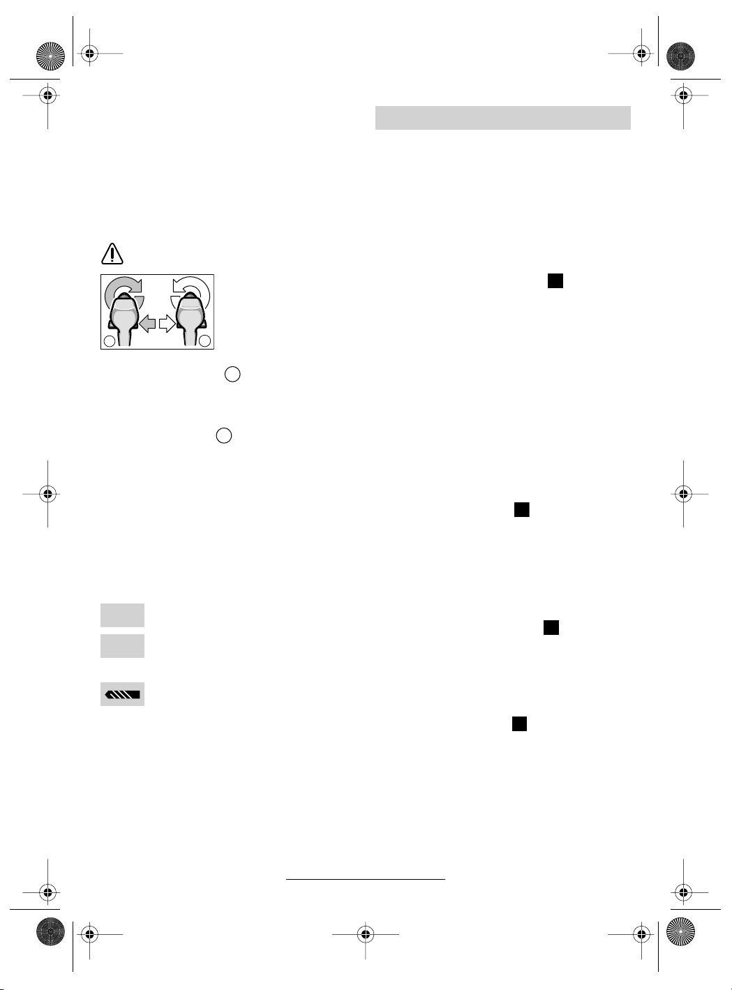
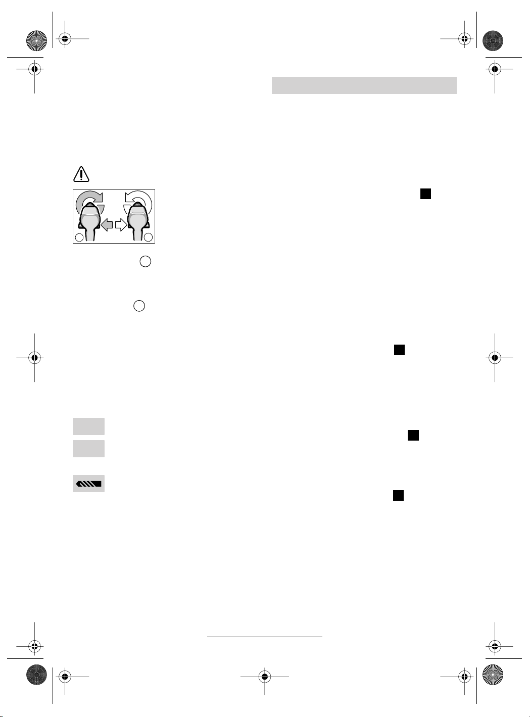
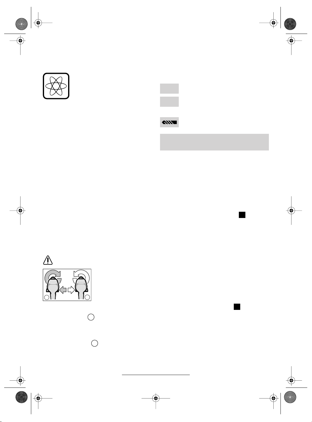
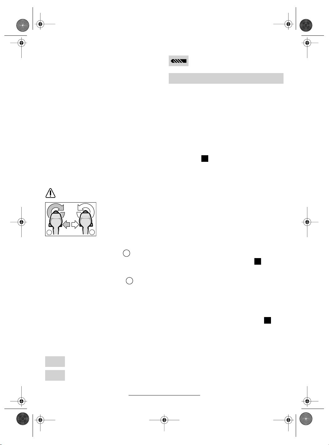
Umschalten der Drehrichtung
Den Drehrichtungsumschalter 5 nur bei
Stillstand betätigen.
Mit dem Drehrichtungsumschalter
Drehrichtung der Maschine umgeschaltet. Bei
a
Drehrichtung rechts ( )
Den Drehrichtungsumschalter nach links bis zum
Anschlag durchdrücken (Normalbetrieb: Bohren,
Eindrehen von Schrauben etc.).
Drehrichtung links ( )
Den Drehrichtungsumschalter nach rechts bis
zum Anschlag durchdrücken (Lösen bzw. Herausdrehen von Schrauben und Muttern).
betätigtem Ein-/Aus-
b
schalter
nicht möglich.
a
b
wird die
ist dies jedoch
Drehmoment einstellen
Bei richtiger Einstellung des Drehmoments öffnet
die Überrastkupplung, sobald die Schraube bündig in das Material eingedreht bzw. das eingestellte Drehmoment erreicht ist. Beim Herausdrehen eine höhere Einstellung wählen, bzw. auf
das Symbol „Bohren“ stellen.
Schwache Einstellung, z. B. kleine
1
Schrauben, weiche Werkstoffe.
Starke Einstellung, z. B. große Schrau-
25
ben, harte Werkstoffe.
Bohren
Den Drehmoment-Einstellring 2 auf das
Symbol „Bohren“ stellen.
Akku-Schrauber Display
Das Display
aktiviert.
Nach einiger Zeit schaltet sich das Display in den
Standby-Modus. Das Display
setzen des Akkus
beiden Tasten am Display wieder aktiviert werden.
Bei Temperaturen unter 0 °C ist die Funktion des
Displays eingeschränkt.
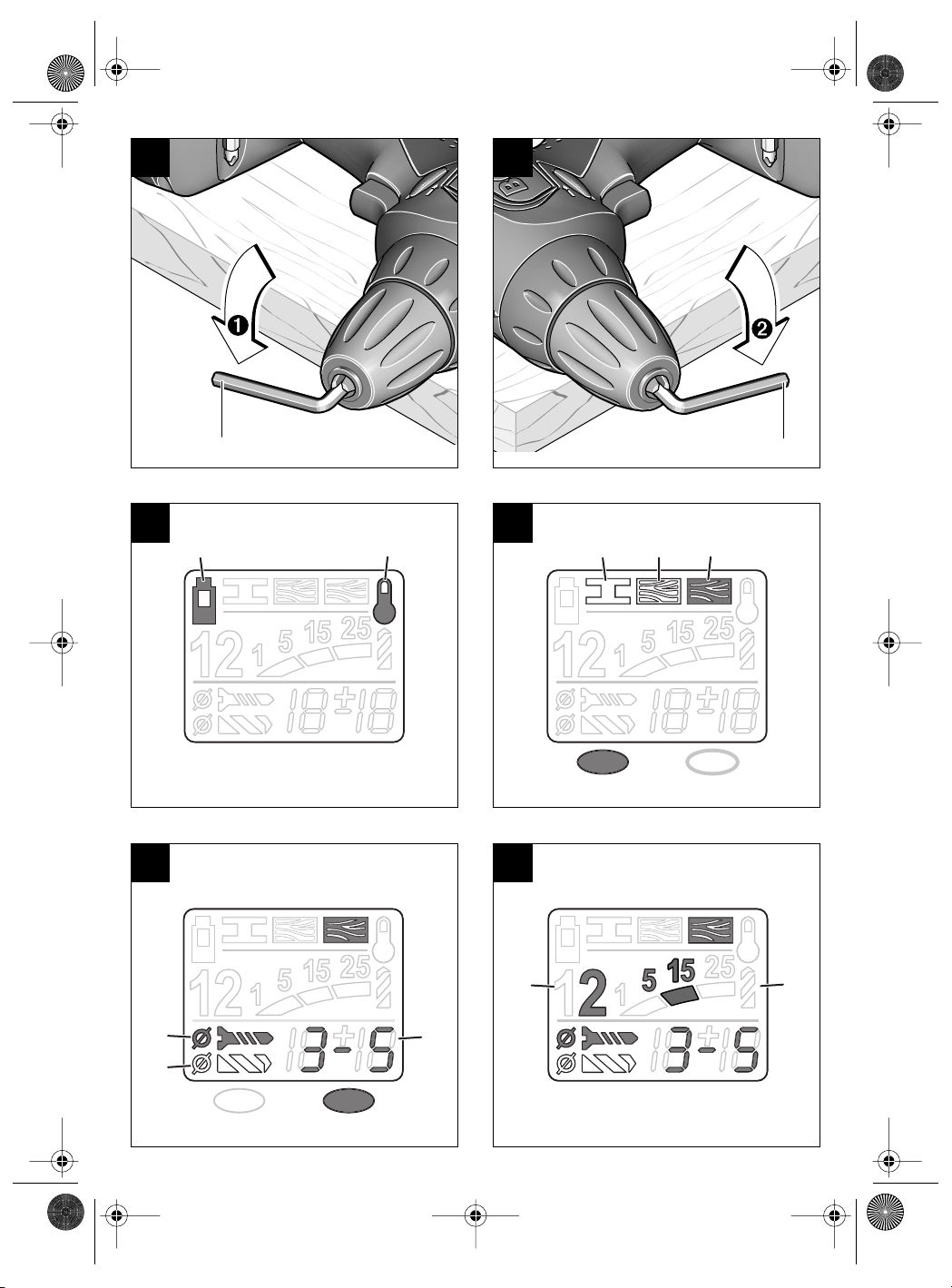
Warnhinweise (siehe Bild )
Die Funktion der Warnhinweise ist auch im
Standby-Modus gegeben.
➊
Der Akku ist fast entladen:
Der Motor ist überhitzt:
➋
➯ Schalten Sie das Gerät ab oder lassen Sie
es einige Zeit unbelastet im Leerlauf laufen,
um es abzukühlen. Warten Sie, bis die Anzeige erlischt.
10 wird beim Einsetzen des Akkus 7
10 kann durch Ein-
oder durch Drücken einer der
E
Laden Sie den Akku auf.
Einstellungshilfe
Die Anzeige dient der Orientierung. Die Werte
sind durch einen praktischen Versuch zu überprüfen.
Materialwahl (siehe Bild )
Wählen Sie das zu bearbeitende Material durch
(mehrfaches) Drücken der linken Taste aus:
F
➌ Stahl
➍ Weichholz
➎ Hartholz
Das Beispiel zeigt: Hartholz.
Anwendungswahl (siehe Bild )
Wählen Sie den Anwendungsfall durch (mehrfaches) Drücken der rechten Taste aus:
G
➏+➑ Schraube eindrehen (4 Durchmesserbe-
reiche)
➐+➑ Loch bohren (2 Durchmesserbereiche)
Empfehlung (siehe Bild )
Die Anzeige liefert eine Empfehlung für die optimale Einstellung Ihres Akku-Bohrschraubers.
Stellen Sie die vorgeschlagenen Werte an Ihrem
Akku-Bohrschrauber ein.
H
➒ 1. Gang/ 2. Gang
➓ Drehmomentbereich (Stufe 1–5, 5 – 15,
15–25, „Bohren“)
Das Beispiel zeigt: 2. Gang, Drehmomentbereich 5–15.
6 • 2 609 932 287 • 03.10
Deutsch - 3

2 609 932 287 - Buch Seite 4 Mittwoch, 22. Oktober 2003 1:58 13
Bohrfutter wechseln
■ Vor allen Arbeiten am Gerät den Akku her-
ausnehmen.
Das Bohrfutter ist gegen das Lösen von der Bohrspindel mit der Sicherungsschraube 13 gesichert.
Das Bohrfutter ganz öffnen und die Sicherungsschraube 13 durch Drehen im Uhrzeigersinn vollständig herausschrauben (siehe Bild ).
Bohrfutter lösen (siehe Bild )
Die Maschine auf eine standfeste Unterlage
(z. B. Werkbank) legen. Die Maschine festhalten
und das Bohrfutter wie eine Schraube durch
Linksdrehen lösen (
futter wird durch einen Schlag auf den langen
Schaft des Innensechskantschlüssels 14 gelöst.
➊). Ein festsitzendes Bohr-
Bohrfutter festziehen (siehe Bild )
Die Montage des Bohrfutters erfolgt in umgekehrter Reihenfolge (
).
➋
B
C
D
Arbeitshinweise
Softgrip
Die rückseitig angebrachte Griff-Fläche 9 (Softgrip) erhöht die Abrutschsicherheit und sorgt dadurch für bessere Griffigkeit und Handlichkeit des
Gerätes.
Durch die Gummierung wird gleichzeitig eine vibrationshemmende Wirkung erzielt.
Tipps
■ Verwenden Sie nur zum Schraubenkopf passende Schrauberklingen/Bits.
■ Bei Eindrehen größerer, längerer Schrauben
in harten Werkstoffen am besten vorbohren.
■ Beim Bohren in Metall nur einwandfreie geschärfte HSS-Bohrer (HSS = HochleistungsSchnell-Schnittstahl) verwenden. Entsprechende Qualität garantiert das Bosch-Zubehör-Programm.
Wartung und Reinigung
■ Vor allen Arbeiten am Gerät den Akku her-
ausnehmen.
■ Gerät und Lüftungsschlitze stets sauber
halten, um gut und sicher zu arbeiten.
Sollte das Gerät trotz sorgfältiger Herstellungsund Prüfverfahren einmal ausfallen, ist die Reparatur von einer autorisierten Kundendienststelle
für Bosch-Elektrowerkzeuge ausführen zu lassen.
Bei allen Rückfragen und Ersatzteilbestellungen
bitte unbedingt die 10-stellige Bestellnummer laut
Typenschild des Gerätes angeben.
Umweltschutz
Rohstoffrückgewinnung statt
Müllentsorgung
Gerät, Zubehör und Verpackung
sollten einer umweltgerechten Wiederverwertung zugeführt werden.
Diese Anleitung ist aus chlorfrei gefertigtem Recycling-Papier hergestellt.
Zum sortenreinen Recycling sind Kunststoffteile
gekennzeichnet.
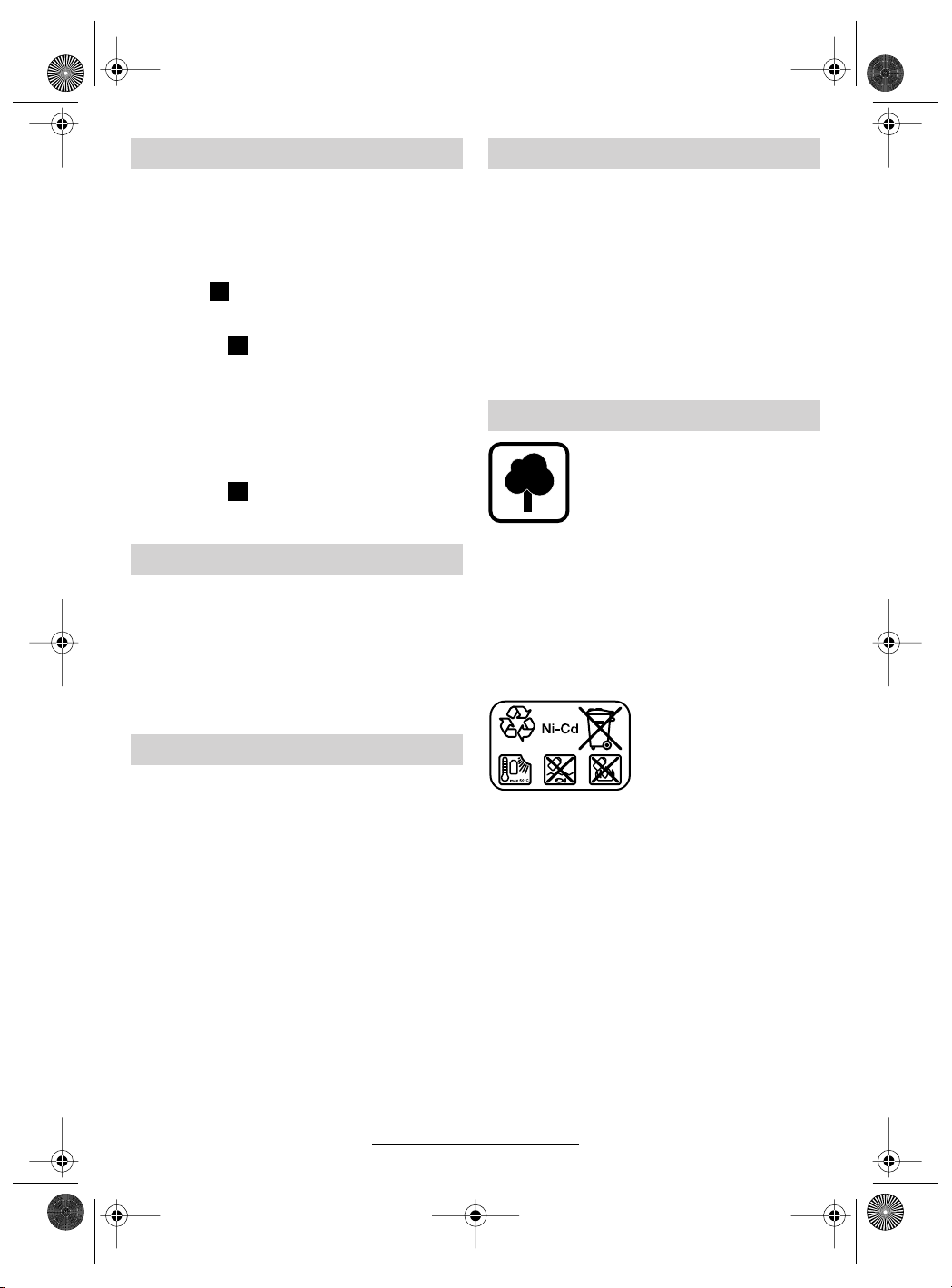
Nickel-Cadmium-Akku:
Wenn Ihr Produkt mit einem Nickel-CadmiumAkku ausgerüstet ist,
muss der Akku gesammelt, recycelt oder auf
umweltfreundliche Weise
entsorgt werden.
Defekte oder verbrauchte Akkus müssen gemäß
Richtlinie 91/157/EWG recycelt werden.
Nicht mehr gebrauchsfähige Akkus/Batterien
können direkt abgegeben werden bei:
Deutschland
Recyclingzentrum Elektrowerkzeuge
Osteroder Landstraße 3
37589 Kalefeld
Schweiz
Batrec AG
3752 Wimmis BE
In Deutschland sind nicht mehr gebrauchsfähige
Geräte zum Recycling beim Handel abzugeben
oder (ausreichend frankiert) direkt einzuschicken
an:
Recyclingzentrum Elektrowerkzeuge
Osteroder Landstraße 3
37589 Kalefeld
7 • 2 609 932 287 • 03.10
Deutsch - 4
2 609 932 287 - Buch Seite 5 Mittwoch, 22. Oktober 2003 1:58 13
Geräusch-/Vibrationsinformation Service und Kundenberater
Messwerte ermittelt entsprechend EN 50 260.
Der A-bewertete Schalldruckpegel des Gerätes
ist typischerweise kleiner als 70 dB (A).
Der Geräuschpegel beim Arbeiten kann
85 dB (A) überschreiten.
Gehörschutz tragen!
Die Hand-Arm-Vibration ist typischerweise niedriger als 2,5 m/s
2
.
Explosionszeichnungen und Informationen
zu Ersatzteilen finden Sie unter:
www.bosch-pt.com
www.powertool-portal.de, das Internetportal
für Heimwerker und Gartenfreunde
www.dha.de, das komplette Service-Angebot
der Deutschen Heimwerker Akademie
Deutschland
Robert Bosch GmbH
Servicezentrum Elektrowerkzeuge
Zur Luhne 2
37589 Kalefeld
✆ Service: ....................................... 01 80 - 3 35 54 99
........................................... +49 (0) 55 53 / 20 22 37
Fax:
✆ Kundenberater: ...................... 01 80 - 3 33 57 99
Österreich
ABE Service GmbH
Jochen-Rindt-Straße 1
1232 Wien
✆ Service: ..................................... +43 (0)1 / 61 03 80
............................................... +43 (0)1 / 61 03 84 91
Fax:
✆ Kundenberater:............ +43 (0)1 / 797 22 3066
E-Mail: abe@abe-service.co.at
8 • 2 609 932 287 • 03.10
Schweiz
✆ Service: ................................. +41 (0)1 / 8 47 16 16
Fax:
✆ Kundenberater:...... Grüne Nr. 0 800 55 11 55
Wir erklären in alleiniger Verantwortung, dass dieses Produkt mit den folgenden Normen oder normativen Dokumenten übereinstimmt: EN 50 260
(Akku-Geräte) bzw. EN 60 335 (Akku-Ladegeräte) gemäß den Bestimmungen der Richtlinien
73/23/EWG, 89/336/EWG, 98/37/EG.
Dr. Egbert Schneider Dr. Eckerhard Strötgen
Senior Vice President Head of Product
Engineering Certification
Robert Bosch GmbH, Geschäftsbereich Elektrowerkzeuge
Änderungen vorbehalten
Deutsch - 5
.................................................. +41 (0)1 / 8 47 16 57
Konformitätserklärung
03
2 609 932 287 - Buch Seite 1 Mittwoch, 22. Oktober 2003 1:58 13
Tool Specifications
Cordless screwdriver PSR 9,6 VE-2 PSR 12 VE-2 PSR 14,4 VE-2 PSR 18 VE-2
Order number 0 603 943 6.. 0 603 943 5.. 0 603 943 4.. 0 603 943 3..
No-load speed
1st gear [rpm] 0– 390 0– 390 0 –400 0 – 400
2nd gear [rpm] 0– 1 250 0–1 250 0 – 1 250 0 – 1 250
Torque adjustment range [Nm] 0.7 –9.0 0.7– 9.0 0.7 – 9.0 0.7 –9.0
max. torque for hard/soft
screwdriving application
according to ISO 5393
Maximum drilling Ø
(1st/2nd gear)
Steel [mm] 10/8 10/10 10/ 10 12/ 12
Wood [mm] 18/16 20/19 28 / 20 30/22
Screw diameter, max. [mm] 6 6 7 8
Chuck clamping range [mm] 1–10 1–10 1–10 1–10
Drill spindle thread 3/8" 3/8" 3/8" 3/8"
Weight without battery,
approx.
Battery
Temperature control NTC NTC NTC NTC
Rated voltage [V=] 9.6 12 14.4 18
Capacity [Ah] 1.5 1.5 1.5 1.5
Weight, approx. [kg] 0.5 0.6 0.75 1.0
Please observe the order number of your machine. The trade names of the individual machines may vary.
[Nm] 22/8 24/12 30/ 16 42/ 22
[kg] 1.0 1.0 1.0 1.2
Machine Elements
1 Gear selector
2 Torque setting ring
3 Keyless chuck
4 On/Off switch
5 Rotational direction switch
6 Screwdriver bit*
7 Battery*
8 Battery unlocking button
9 Soft grip
10 Display
11 Screwdriver attachment (bit)*
12 Universal bit holder*
13 Locking screw
14 Allen key*
* Not all of the accessories illustrated or described are
included as standard delivery.
Intended Use
The machine is intended for the screwing in and
loosening of screws as well as for drilling in wood,
metal, ceramic and plastic.
9 • 2 609 932 287 • 03.10
English - 1
For Your Safety
Working safely with this machine is possible only when the
operating and safety information
are read completely and the instructions contained therein are
strictly followed. In addition, the
general safety notes in the enclosed booklet
must be observed.
■ Wear safety goggles.
■ For long hair, wear hair protection. Work only
with closely fitting clothes.
■ Before each use, check the machine and bat-
tery. If damage is detected, do not use the machine. Have repairs performed only by a qualified technician. Never open the machine yourself.
■ Before any work on the machine itself (e. g.
maintenance, tool change, etc.) as well as
when transporting and storing, always set
the rotational direction switch to the centre
position. Otherwise danger of injury is given
when unintentionally actuating the On/Off
switch.
2 609 932 287 - Buch Seite 2 Mittwoch, 22. Oktober 2003 1:58 13
■ Convince yourself before using that the battery
is securely seated in the machine.
■ Use appropriate detectors to determine if
utility lines are hidden in the work area or
call the local utility company for assistance.
Contact with electric lines can lead to fire and
electric shock. Damaging a gas line can lead
to explosion. Penetrating a water line causes
property damage.
■ Hold the machine tightly: When driving in
screws, high reaction moments can briefly occur.
■ Secure the workpiece. A workpiece clamped
with clamping devices or in a vice is held more
secure than by hand.
■ Never allow children to use the machine.
■ Bosch is only able to ensure perfect operation
of the machine if the original accessories intended for it are used.
Battery and Battery Charger
■ The enclosed operating instructions for the
battery charger must be read carefully!
■ Do not open the battery, and protect it from impact. Store in a dry and frost-free place.
■ Allow a heated battery to cool before charging.
■ Protect the battery from heat and fire: Danger
of explosion! Do not place the battery on radiators or expose to strong sun rays for a longer
time; temperatures over 50 °C cause damage.
■ Do not dispose of the battery in household
waste or discard into fire or water.
Before Putting into Operation
Battery Charging
A battery that is new or has not been used for a
longer period does not develop its full capacity
until after approximately 5 charging/discharging
cycles.
To remove the battery 7, press the unlocking buttons 8 and pull out the battery downwards. Do not
exert any force.
The battery is equipped with an NTC temperature
control which allows charging only within a temperature range of between 0 °C and 45 °C. A long
battery service life is achieved in this manner.
A significantly reduced working period after
charging indicates that the batteries are used and
must be replaced.
■ Observe the notes on environmental protection.
10 • 2 609 932 287 • 03.10
English - 2
Changing the Tool
Open the drill chuck 3 by turning until the tool can
be inserted. Insert the tool.
Firmly tighten the sleeve of the keyless chuck 3
by hand. This automatically locks the chuck.
Rotate the sleeve in the reverse direction to remove the tool.
Screwdriving (see figure )
Directly clamp the screwdriver bit 6 into the drill
chuck or use the additional universal bit holder 12
when operating with hex shank bits 11.
A
Initial Operation
Inserting the Battery
Set the rotational direction switch 5 to the centre
position = lock-off and allow the charged battery 7 to engage into the handle.
Switching On and Off
To start the machine, press the On/Off switch 4
and keep it depressed.
The machine runs with variable
speed between 0 and maximum,
depending on the pressure applied
to the On/Off switch 4. Light pressure results in a low rotational
speed thus allowing smooth, controlled starts. Do not strain the machine so heavily that it comes to a
standstill.
To switch off the machine, release the On/Off
switch 4.
Gear Selection, Mechanical
Two speed ranges can be preselected with the
gear selector 1:
1st gear: Low rotational speed, high power.
2nd gear: High rotational speed, less power.
The speed settings may only be changed when
the machine is motionless. If the speed setting
has not quite notched in properly, briefly press
the On/Off switch 4.
2 609 932 287 - Buch Seite 3 Mittwoch, 22. Oktober 2003 1:58 13
Fully Automatic Spindle Locking
(Auto-Lock)
The drill spindle is locked when the On/Off
switch 4 is not pressed.
This makes quick and easy changing of the tool
in the drill chuck possible.
Reversing the Rotational Direction
Operate the rotational direction
switch 5 only at a standstill.
The rotational direction
switch 5 is used to reverse the rotational direction of the machine. How-
a
Right Rotation ( )
Turn the rotational direction switch through to the
left stop (normal operation: drilling, screwdriving,
etc.).
Left Rotation ( )
Press the rotational direction switch through to
the right stop (for loosening and unscrewing
screws and nuts).
ever, this is not possible
b
with the On/Off switch 4
actuated.
a
b
Setting the Torque
With the correct setting, the clutch disengages as
soon as the screw is driven flush into the material
or the set torque is reached. Select a higher setting when driving out screws, or set to the “Drilling” symbol.
Low setting, e. g., small screws, soft
1
materials.
High setting, e. g., large screws, hard
25
materials.
Drilling
Set the torque setting ring 2 to the “Drilling” symbol.
Cordless Screwdriver Display
The display 10 is activated when the battery 7 is
inserted.
After a while the display switches to the stand-by
mode. The display 10 can be activated again by
inserting the battery 7 or by pressing one of the
two push-button keys on the display.
For temperatures below 0 °C the function of the
display is limited.
Warning Indicators (see figure )
The function of the warning indicators is also operative in stand-by mode.
E
➊ The battery is almost empty:
➯ Recharge the battery.
The motor is starting to overheat:
➋
➯ Switch the machine off and allow to cool
down. Alternatively, run the machine at full
speed without load until the warning indicator
goes out.
Adjustment Aid
The display is for guidance. The settings are to
be checked by carrying out a practical test.
Material Selection (see figure )
Select the material to be worked by (multiple)
pressing of the left push-button key:
F
➌ Steel
➍ Softwood
➎ Hardwood
Shown in the example: Hardwood.
Application Selection (see figure )
Select the application by (multiple) pressing of
the right push-button key:
G
➏+➑ Driving in screws (4 Diameter ranges)
➐+➑ Drilling holes (2 Diameter ranges)
Recommendation (see figure )
The indication gives a recommendation for the
optimum setting of your cordless screwdriver. Adjust the proposed values on your cordless screwdriver.
H
➒ 1st gear/ 2nd gear
➓ Torque range (Level 1 – 5, 5– 15,
15 – 25, “Drilling”)
Shown in the example: 2nd gear; Torque
range 5 – 15.
11 • 2 609 932 287 • 03.10
English - 3
2 609 932 287 - Buch Seite 4 Mittwoch, 22. Oktober 2003 1:58 13
Replacing the Drill Chuck
■ Before any work on the machine itself, remove the battery.
The locking screw 13 secures the drill chuck
against loosening from the drill spindle. Fully
open the drill chuck and completely unscrew the
locking screw 13 by turning in clockwise direction
(see figure ).
B
Loosening the Drill Chuck
(see figure )
Place the machine on a stable surface (e. g.
workbench). Hold the machine firmly and loosen
the chuck by turning to the left, as when unscrewing a screw (
the long end of the Allen key 14 a sharp blow.
C
➊). Loosen a tight chuck by giving
Tightening the Drill Chuck
(see figure )
The drill chuck is mounted in reverse order (➋).
D
Operating Instructions
Soft grip
The gripping surface 9 on the rear of the handle
(soft grip) reduces the danger of slipping and
thereby improves the grip on the machine and the
handling.
At the same time, the rubber coating achieves a
vibration-reducing effect.
Tips
■ Use only screwdriver bits that fit properly in the
head of the screw.
■ When driving in larger and/or longer screws in
hard material, it is advisable to drill a pilot hole
first.
■ For drilling in metal, use only perfectly sharpened HSS drills. The appropriate quality is
guaranteed by the Bosch accessories program.
Maintenance and Cleaning
■ Before any work on the machine itself, remove the battery.
■ For safe and proper working, always keep
the machine and the ventilation slots clean.
If the machine should fail despite the care taken
in manufacturing and testing procedures, repair
should be carried out by an after-sales service
centre for Bosch power tools.
In all correspondence and spare parts orders,
please always include the 10-digit order number
given on the nameplate of the machine.
Environmental Protection
Recycle raw materials instead of disposing as
waste
The machine, accessories and packaging should
be sorted for environmental-friendly recycling.
These instructions are printed on recycled paper
manufactured without chlorine.
The plastic components are labelled for categorized recycling.
Nickel-cadmium-battery:
If your product is equipped
with a nickel-cadmium-battery, the battery must be
collected, recycled or disposed of in an environmentally-friendly way.
Defective or worn out batteries must be recycled
according to the guidelines 91/157/EEC.
Batteries no longer suitable for use can be
directly returned at:
Great Britain
Robert Bosch Ltd. (B.S.C.)
P.O. Box 98
Broadwater Park
North Orbital Road
Denham-Uxbridge
Middlesex UB 9 5HJ
✆ Service............................ +44 (0) 18 95 / 83 87 82
✆ Advice line.................... +44 (0) 18 95 / 83 87 91
............................................. +44 (0)18 95 / 83 87 89
Fax
12 • 2 609 932 287 • 03.10
English - 4
2 609 932 287 - Buch Seite 5 Mittwoch, 22. Oktober 2003 1:58 13
Noise/Vibration Information
Measured values determined according to
EN 50 260.
Typically the A-weighted sound pressure level of
the product is less than 70 dB (A).
The noise level when working can exceed
85 dB (A).
Wear hearing protection!
The typical hand/arm vibration is below 2.5 m/s
Service and Customer
Assistance
Exploded views and information on spare
parts can be found under:
www.bosch-pt.com
Great Britain
Robert Bosch Ltd. (B.S.C.)
P.O. Box 98
Broadwater Park
North Orbital Road
Denham-Uxbridge
Middlesex UB 9 5HJ
✆ Service............................ +44 (0) 18 95 / 83 87 82
✆ Advice line .................... +44 (0) 18 95 / 83 87 91
............................................. +44 (0) 18 95 / 83 87 89
Fax
Ireland
Beaver Distribution Ltd.
Greenhills Road
Tallaght-Dublin 24
✆ Service................................... +353 (0)1 / 414 9400
.................................................... +353 (0)1 / 459 8030
Fax
Australia
Robert Bosch Australia Ltd.
RBAU/SPT2
1555 Centre Road
P.O. Box 66 Clayton
3168 Clayton/Victoria
✆ ............................................... +61 (0)1 / 800 804 777
............................................... +61 (0)1 / 800 819 520
Fax
www.bosch.com.au
E-Mail: CustomerSupportSPT@au.bosch.com
New Zealand
Robert Bosch Limited
14-16 Constellation Drive
Mairangi Bay
Auckland
New Zealand
✆ ..................................................... +64 (0)9 / 47 86 158
..................................................... +64 (0)9 / 47 82 914
Fax
2
.
Declaration of Conformity
We declare under our sole responsibility that this
product is in conformity with the following standards or standardization documents. EN 50 260
(Battery powered products) and EN 60 335 (Battery charger) according to the provisions of the directives 73/23/EEC, 89/336/EEC, 98/37/EC.
03
Dr. Egbert Schneider Dr. Eckerhard Strötgen
Senior Vice President Head of Product
Engineering Certification
Robert Bosch GmbH, Geschäftsbereich Elektrowerkzeuge
Subject to change without notice
13 • 2 609 932 287 • 03.10
English - 5
2 609 932 287 - Buch Seite 1 Mittwoch, 22. Oktober 2003 1:58 13
Caractéristiques techniques
Perceuse-visseuse sans fil PSR 9,6 VE-2 PSR 12 VE-2 PSR 14,4 VE-2 PSR 18 VE-2
Référence 0 603 943 6.. 0 603 943 5.. 0 603 943 4.. 0 603 943 3..
Régime à vide
ère
1
vitesse [tr/min] 0 – 390 0 – 390 0 – 400 0 – 400
ème
2
vitesse [tr/min] 0 –1 250 0–1 250 0–1 250 0 – 1 250
Plage de réglage du couple [Nm] 0,7 –9,0 0,7 –9,0 0,7– 9,0 0,7 – 9,0
Couple max. vissage dur/
tendre suivant ISO 5393
Ø perçage max.
ère/2ème
(1
vitesse)
Acier [mm] 10/8 10/10 10/10 12 / 12
Bois [mm] 18/16 20/19 28/20 30 / 22
Ø des vis, max. [mm] 6 6 7 8
Fixation du mandrin de
perçage
Fixation de la broche 3/8" 3/8" 3/8" 3/8"
Poids sans accumulateur,
env.
Accumulateur
Contrôle de température NTC NTC NTC NTC
Tension nominale [V=] 9,6 12 14,4 18
Capacité [Ah] 1,5 1,5 1,5 1,5
Poids, env. [kg] 0,5 0,6 0,75 1,0
Faire attention au numéro de référence de la machine. Les désignations commerciales des différentes machines peuvent
varier.
[Nm] 22/8 24/12 30/16 42 / 22
[mm] 1–10 1–10 1–10 1–10
[kg] 1,0 1,0 1,0 1,2
Eléments de la machine Utilisation conformément à la
1 Commutateur de vitesse
2 Bague de réglage du couple
3 Mandrin à serrage rapide
4 Interrupteur Marche/Arrêt
5 Commutateur du sens de rotation
6 Lame de tournevis*
7 Accumulateur*
8 Touche de déverrouillage de l’accumulateur
9 Point d’appui souple (antidérapant)
10 Ecran digital de la perceuse-visseuse
sans fil
11 Embout tournevis*
12 Porte-embout universel*
13 Vis de retenue
14 Clé mâle pour vis à six pans creux*
* Les accessoires reproduits ou décrits ne sont pas
forcément fournis avec la machine.
14 • 2 609 932 287 • 03.10
Français - 1
destination de l’appareil
L’appareil est conçu pour le vissage et le dévissage des vis ainsi que pour le perçage dans le
bois, le métal, le céramique et les matières plastiques.
Pour votre sécurité
Pour travailler sans risque avec
cet appareil, lire intégralement
au préalable les instructions
d’utilisation et les remarques
concernant la sécurité. Respec-
ter scrupuleusement les indications et les consignes qui y sont données.
Respecter en plus les indications générales
de sécurité se trouvant dans le cahier ci-joint.
■ Porter des lunettes de protection.
■ Les personnes portant les cheveux longs doi-
vent se munir d’un protège-cheveux. Ne travailler qu’avec des vêtements près du corps.
2 609 932 287 - Buch Seite 2 Mittwoch, 22. Oktober 2003 1:58 13
■ Avant chaque utilisation, vérifier l’appareil et
l’accumulateur. Ne jamais mettre en marche
un appareil endommagé. Les réparations ne
doivent être confiées qu’à un spécialiste. Ne
jamais ouvrir l’appareil soi-même.
■ Avant d’effectuer des travaux sur l’appareil
(p. ex. travaux d’entretien, changement
d’outils, etc.) et avant de le transporter ou
stocker, toujours mettre le commutateur de
sens de rotation en position médiane. Si-
non, il y a risque de blessure lorsqu’on appuie
par mégarde sur l’interrupteur Marche/Arrêt.
■ Avant utilisation, toujours contrôler que l’accumulateur est correctement en place.
■ Utiliser des détecteurs appropriés afin de
déceler des conduites cachées ou consulter les entreprises de distribution (de gaz et
d’électricité) locales.
Un contact avec des conduites d’électricité
peut provoquer un incendie ou un choc électrique. L’endommagement d’une conduite de
gaz peut provoquer une explosion. La perforation d’une conduite d’eau provoque des dégâts
matériels.
■ Bien tenir la machine : Lors du vissage, il peut
y avoir des couples de réaction élevés.
■ Bloquer la pièce à travailler. Une pièce à tra-
vailler serrée par des dispositifs de serrage ou
dans un étau est fixée de manière plus sûre
que si elle est seulement tenue d’une main.
■ Ne jamais permettre aux enfants d’utiliser cet
appareil.
■ Bosch ne peut garantir un fonctionnement impeccable que si les accessoires Bosch d’origine prévus pour cet appareil sont utilisés.
Accumulateur et chargeur
■ Lire absolument le mode d’emploi du char-
geur ci-joint !
■ Ne pas ouvrir l’accumulateur. Le protéger de
tout choc mécanique. L’entreposer dans un
endroit sec et à l’abri du gel.
■ Avant de recharger un accumulateur surchauffé, le laisser refroidir.
■ Protéger l’accumulateur contre toute exposition à la chaleur ou au feu : risque d’explosion ! Ne pas poser l’accumulateur sur un
corps chaud (radiateur, par exemple). Ne pas
l’exposer trop longtemps à un fort ensoleillement. Les températures dépassant 50 °C lui
sont néfastes.
■ Ne pas jeter l’accu à la poubelle, ni dans les
flammes ou dans l’eau.
Avant la mise en service
Recharge de l’accumulateur
Un accu neuf ou un accu qui n’a pas été utilisé
pendant une période assez longue, n’atteint sa
pleine puissance qu’après environ cinq cycles de
charge et de décharge.
Pour sortir l’accumulateur 7, appuyer sur les boutons de déverrouillage 8 et retirer l’accumulateur
vers le bas. Ne pas forcer.
L’accumulateur est doté d’un dispositif de surveillance de la température NTC ne permettant la
charge que dans une plage de température comprise entre 0 °C et 45 °C. La longévité de l’accumulateur s’en trouve ainsi accrue.
Si le temps de service des accus se raccourcit
considérablement après un processus de
charge, cela indique que les accus sont usés et
qu’ils doivent être remplacés.
■ Observer les consignes relatives à la protection de l’environnement.
Changement de l’outil
Ouvrir le mandrin de perçage 3 par un mouvement de rotation jusqu’à ce que l’outil puisse être
monté. Monter l’outil.
Bien visser la douille du mandrin de perçage à
serrage rapide 3 en la tournant fortement à la
main. Le mandrin de perçage se trouve alors verrouillé automatiquement.
Tourner le corps dans le sens inverse pour retirer
l'outil.
Vissage (voir figure )
Serrer les lames de tournevis 6 directement dans
le mandrin de perçage ou en cas d’utilisation
d’embouts tournevis (bits) 11, utiliser en plus un
porte-embout universel 12.
A
Mise en service
Mise en place de l’accumulateur
Mettre le commutateur du sens de rotation 5
dans la position médiane = verrouillage de mise
en fonctionnement et faire encliqueter l’accu
chargé 7 dans la poignée.
15 • 2 609 932 287 • 03.10
Français - 2
2 609 932 287 - Buch Seite 3 Mittwoch, 22. Oktober 2003 1:58 13
Mise en fonctionnement/Arrêt
Afin de mettre l’appareil en fonctionnement,
appuyer sur l’interrupteur Marche/Arrêt 4 et le
maintenir appuyé.
En fonction de la pression exercée
sur l’interrupteur Marche/Arrêt 4,
l’appareil fonctionne à une vitesse
comprise entre 0 et le maximum.
Une légère pression fait tourner
l’appareil à petite vitesse, ce qui
permet un démarrage précis et en
douceur. Ne pas trop solliciter l’appareil qui risque sinon de s’arrêter.
Afin d’arrêter l’appareil, relâcher l’interrupteur
Marche/Arrêt 4.
Commutation mécanique de la vitesse
Le commutateur de vitesse 1 permet de sélectionner deux plages de vitesse de rotation :
ère
vitesse : Petite vitesse, force élevée.
1
ème
vitesse : Vitesse élevée, force faible.
2
On ne peut changer de vitesse que lorsque la
machine est à l'arrêt. Si la vitesse ne s'enclenche
pas complètement, appuyer un court instant sur
l'interrupteur Marche/Arrêt 4.
Blocage de broche automatique
(Auto-Lock)
Lorsque l’interrupteur Marche/Arrêt 4 n’est pas
appuyé, la broche de perçage est bloquée.
Ceci permet de remplacer l’outil utilisé dans le
mandrin de manière rapide, aisée et facile.
Inversion du sens de rotation
N’actionner le commutateur du sens de
rotation 5 qu’à l’arrêt total de l’appareil.
Le sens de rotation de
l’appareil peut être modifié à l’aide du commutateur du sens de rota-
a
Rotation à droite ( )
Pousser à fond le commutateur du sens de rotation vers la gauche (service normal : perçage,
vissage, etc.).
Rotation à gauche ( )
Repousser à fond le commutateur du sens de rotation vers la droite « Rotation à droite » (pour les
travaux de desserrage, de dévissage de vis et
d’écrous).
tion 5. Cela n’est toute-
b
fois pas possible en
actionnant l’interrupteur
Marche/Arrêt 4.
a
b
Réglage du couple
Le réglage est correct lorsque l’embrayage à
crans est déclenché dès que la tête de la vis affleure le matériau ou que le couple préréglé est
atteint. Pour dévisser, choisir un réglage plus
élevé, ou régler sur le symbole « Perçage ».
Couple réduit p. ex. petites vis, maté-
1
riaux tendres.
Couple élevé, p. ex. vis de taille impor-
25
tante, matériaux durs.
Perçage
Positionner la bague de réglage du couple 2 sur le symbole « Perçage ».
Ecran digital de la
perceuse-visseuse sans fil
L’écran digital 10 est activé une fois que l’accumulateur 7 est mis en place.
Après un certain temps, l’écran digital se met en
mode de veille. Pour réactiver l’écran digital 10,
mettre en place l’accumulateur 7 ou appuyer sur
l’une des deux touches se trouvant sur l’écran digital.
Le fonctionnement de l’écran digital se trouve réduit à des températures inférieures à 0 °C.
Avertissements (voir figure )
Les avertissements sont indiqués même en
mode de veille.
E
➊ L’accumulateur est presque déchargé :
➯ Recharger l’accumulateur.
Le moteur est trop chaud :
➋
➯ Arrêter l’appareil ou le laisser tourner à vide
pendant un certain temps afin de le refroidir.
Attendre que l’affichage s’éteigne.
Aide de réglage
L’affichage est donné à titre de référence. Les valeurs de réglage doivent être contrôlées par un
essai pratique.
Choix du matériau (voir figure )
Choisir le matériau à travailler en appuyant (plusieurs fois) sur la touche gauche :
F
➌ Acier
➍ Bois tendre
➎ Bois dur
Ici, à titre d’exemple : bois dur.
16 • 2 609 932 287 • 03.10
Français - 3
2 609 932 287 - Buch Seite 4 Mittwoch, 22. Oktober 2003 1:58 13
Sélection de l’utilisation (voir figure )
Sélectionner le travail à effectuer en appuyant
(plusieurs fois) sur la touche droite :
G
➏+➑ Visser une vis (4 plages de diamètres)
➐+➑ Percer un trou (2 plages de diamètres)
Recommandation (voir figure )
L’affichage vous donne une recommandation
pour un réglage optimal de votre perceuse-visseuse sans fil. Régler les valeurs recommandées
sur votre perceuse-visseuse sans fil.
➒ 1
ère
vitesse/2
ème
vitesse
H
➓ Plage de couple (position 1 – 5, 5 – 15, 15 – 25,
« Perçage »)
ème
Ici, à titre d’exemple : 2
couple 5 – 15.
vitesse, plage de
Changement du mandrin
■ Avant toute intervention sur l’appareil pro-
prement dit, retirer l’accumulateur.
Le mandrin de perçage est fixé à l’aide de la vis
de blocage 13 qui l’empêche de se détacher de
la broche de perçage. Ouvrir complètement le
mandrin de perçage et dévisser complètement la
vis de blocage 13 par un mouvement de rotation
dans le sens des aiguilles d’une montre (voir fi-
B
gure ).
Desserrer le mandrin (voir figure )
Poser la machine sur un support stable (p. ex.
établi). Maintenir la machine et dévisser le mandrin comme si c’était une vis, en tournant à gau-
➊). Un mandrin qui serait trop serré peut
che (
être desserré en donnant un léger coup sur le
côté le plus long de la clé mâle coudée pour vis à
six pans creux 14.
Serrer le mandrin (voir figure )
Pour monter le mandrin, procéder en sens inverse (
).
➋
C
D
Instructions d’utilisation
Softgrip
La surface arrière de la poignée 9 évite un glissement de la main et permet ainsi une meilleure
maniabilité de l'appareil.
Grâce au revêtement en caoutchouc, les vibrations sont également atténuées.
Conseils d’utilisation
■ N’utiliser que des lames de tournevis et des
embouts de vissage adaptés à la tête de la vis.
■ Lors du vissage de vis de taille et de longueur
importantes dans des matériaux durs, il est recommandé de percer un avant-trou.
■ Lors de perçage dans les métaux, n’utiliser
que des forets HSS en bon état et bien affûtés
(HSS = aciers super rapides). Le programme
d’accessoires Bosch garantit la qualité des forets.
Nettoyage et entretien
■ Avant toute intervention sur l’appareil pro-
prement dit, retirer l’accumulateur.
■ Pour obtenir un travail sûr et satisfaisant,
nettoyer régulièrement l’appareil ainsi que
ses ouïes de refroidissement.
Si, malgré tous les soins apportés à la fabrication
et au contrôle de l’appareil, celui-ci devait avoir
un défaut, la réparation ne doit être confiée qu’à
une station de service après-vente agréée pour
outillage Bosch.
Pour toute demande de renseignements ou commande de pièces de rechange, nous préciser impérativement le numéro de référence à dix chiffres de la machine.
17 • 2 609 932 287 • 03.10
Français - 4
2 609 932 287 - Buch Seite 5 Mittwoch, 22. Oktober 2003 1:58 13
Instructions de protection de
l’environnement
Récupération des matières premières plutôt
qu’élimination des déchets
Les machines, comme d’ailleurs leurs accessoires et emballages, doivent pouvoir suivre chacune une voie de recyclage appropriée.
Ce manuel d’instructions a été fabriqué à partir
d’un papier recyclé blanchi sans chlore.
Nos pièces plastiques ont ainsi été marquées en
vue d’un recyclage sélectif des différents matériaux.
Accumulateur NickelCadmium : Au cas où vo-
tre produit serait équipé
d’un accu Nickel-Cadmium, l’accu doit être récupéré, recyclé ou éliminé
en conformité avec les réglementations se rapportant à l’environnement.
Les accus usés ou défectueux doivent être recyclés conformément à la directive 91/157/CEE.
Les accus/piles dont on ne peut plus se servir
peuvent être déposés directement auprès de :
Suisse
Batrec AG
3752 Wimmis BE
Bruits et vibrations
Valeurs de mesure obtenues conformément à la
norme européenne 50 260.
La mesure réelle (A) du niveau sonore de l’outil
est inférieure à 70 dB (A).
Le niveau sonore en fonctionnement peut dépasser 85 dB (A).
Munissez-vous d’une protection acoustique !
La vibration de l’avant-bras est en-dessous de
2
2,5 m/s
.
Service Après-Vente
Vous trouverez des vues éclatées ainsi que
des informations concernant les pièces de rechange sous :
www.bosch-pt.com
France
Information par Minitel 11
Nom : Bosch Outillage
Loc : Saint Ouen
Dépt : 93
Robert Bosch France S.A.
Service Après-vente/Outillage
B.P. 67-50, Rue Ardoin
93402 St. Ouen Cedex
✆ Service conseil client.................... 0143 11 9002
Numéro Vert
Belgique
.................................... 0 800 05 50 51
✆ ..................................................... +32 (0)2 / 525 51 43
..................................................... +32 (0)2 / 525 54 20
Fax
E-Mail : Outillage.Gereedschappen@be.bosch.com
Suisse
✆ .................................................... +41 (0)1 / 8 47 16 16
.................................................... +41 (0)1 / 8 47 16 57
Fax
✆ Service conseil client................. 0 800 55 11 55
Déclaration de conformité
Nous déclarons sous notre propre responsabilité
que ce produit est en conformité avec les normes
ou documents normalisés : EN 50 260 (appareils
sans fil) respectivement EN 60 335 (chargeurs
électriques) conformément aux termes des réglementations 73/23/CEE, 89/336/CEE, 98/37/CE.
03
Dr. Egbert Schneider Dr. Eckerhard Strötgen
Senior Vice President Head of Product
Engineering Certification
Robert Bosch GmbH, Geschäftsbereich Elektrowerkzeuge
18 • 2 609 932 287 • 03.10
Sous réserve de modifications
Français - 5
2 609 932 287 - Buch Seite 1 Mittwoch, 22. Oktober 2003 1:58 13
Características técnicas
Atornilladora taladradora
accionada por acumulador
PSR 9,6 VE-2 PSR 12 VE-2 PSR 14,4 VE-2 PSR 18 VE-2
Número de pedido 0 603 943 6.. 0 603 943 5.. 0 603 943 4.. 0 603 943 3..
Revoluciones en vacío
1ª velocidad [min-1] 0 – 390 0 – 390 0 – 400 0 – 400
2ª velocidad [min-1] 0 – 1 250 0–1 250 0–1 250 0 – 1 250
Ajuste del par de giro [Nm] 0,7 – 9,0 0,7 – 9,0 0,7– 9,0 0,7 – 9,0
Par de giro máx. en uniones
a rosca rígidas/blandas
según ISO 5393
[Nm] 22/8 24/12 30/16 42/ 22
Ø de perforación máx.
(1ª /2ª velocidad)
Acero [mm] 10/8 10/10 10/10 12/12
Madera [mm] 18 / 16 20/19 28/20 30/22
Ø de tornillo, máx. [mm] 6 6 7 8
Capacidad de sujeción del
portabrocas
[mm] 1–10 1–10 1–10 1–10
Rosca del husillo de taladrar 3/8" 3/8" 3/8" 3/8"
Peso sin acumulador, aprox. [kg] 1,0 1,0 1,0 1,2
Acumulador
Control de temperatura NTC NTC NTC NTC
Tensión nominal [V=] 9,6 12 14,4 18
Capacidad [Ah] 1,5 1,5 1,5 1,5
Peso, aprox. [kg] 0,5 0,6 0,75 1,0
Preste atención al nº de pedido de su máquina. Las denominaciones comerciales en ciertas máquinas pueden variar.
Elementos del aparato
1 Selector de velocidades
2 Anillo de ajuste de par
3 Portabrocas de sujeción rápida
4 Interruptor de conexión/desconexión
5 Selector de sentido de giro
6 Punta de atornillar*
7 Acumulador*
8 Tecla de desenclavamiento del acumulador
9 Softgrip
10 Display de la atornilladora
11 Lámina de destornillador (bit)*
12 Soporte universal de bits*
13 Tornillo de seguridad
14 Llave macho hexagonal*
* Los accesorios descritos e ilustrados no correspon-
den en parte al material que se adjunta de serie.
allí comprendidas. Adicionalmente deberán
respetarse las instrucciones de seguridad generales comprendidas en el folleto adjunto.
■ Ponerse unas gafas de protección.
■ Si tiene el pelo largo, recójaselo bajo una pro-
tección adecuada. Trabajar únicamente con
vestimenta ceñida al cuerpo.
■ Antes de cada utilización controlar el aparato
y el acumulador. En caso de detectar algun
daño, no continuar usando el aparato. Hacerlo
reparar solamente por personal técnico espe-
Para su seguridad
Solamente puede trabajar sin peligro con el aparato si lee ínte-
gramente las instrucciones de
manejo y las indicaciones de seguridad, ateniéndose estrictamente a las recomendaciones
cializado. No abrir jamás el aparato por su pro-
Utilización reglamentaria
pia cuenta.
El aparato ha sido proyectado para enroscar y
aflojar tornillos, así como para taladrar en madera, metal, cerámica y materiales sintéticos.
19 • 2 609 932 287 • 03.10
Español - 1
A
2 609 932 287 - Buch Seite 2 Mittwoch, 22. Oktober 2003 1:58 13
■ Siempre colocar en posición central el se-
lector del sentido de giro antes de cualquier manipulación en el aparato (p. ej.
mantenimiento, cambio de útil, etc.) así
como al transportarlo y guardarlo. En caso
contrario existe el riesgo de lesión al accionar
accidentalmente el interruptor de conexión/
desconexión.
■ Asegúrese antes de su utilización que el acumulador esté firmemente sujeto en el aparato.
■ Utilice unos instrumentos de exploración
adecuados para detectar tuberías y cables
ocultos, o consulte a su compañía abastecedora local.
El contacto con cables eléctricos puede provocar un incendio o sacudida eléctrica. El deterioro de tuberías de gas puede producir una
explosión. La perforación de una tubería de
agua puede causar daños materiales.
■ Sujetar el aparato firmemente: al trabajar pueden presentarse brevemente unos pares de
reacción elevados.
■ Asegure la pieza de trabajo. Una pieza de tra-
bajo fijada con unos dispositivos de sujeción, o
en un tornillo de banco, se mantiene sujeta de
forma mucho más segura que con la mano.
■ Jamás permita que los niños utilicen el aparato.
■ Bosch solamente puede garantizar el funcionamiento correcto del aparato si se utilizan los
accesorios originales previstos.
Acumulador y cargador
■ ¡Es imprescindible leer las instrucciones
de manejo del cargador que se adjuntan!
■ No abrir el acumulador, y protegerlo contra
golpes. Guardarlo en un lugar seco y libre de
heladas.
■ Dejar enfriar un acumulador caliente antes de
cargarlo.
■ Proteger el acumulador del calor y del fuego:
¡Peligro de explosión! No depositar el acumulador sobre radiadores ni exponerlo durante
tiempo prolongado al sol; las temperaturas por
encima de los 50 °C pueden dañarlo.
■ No tirar el acumulador a la basura, fuego o
agua.
Antes de la puesta en
funcionamiento
Carga del acumulador
Un acumulador nuevo o que no haya sido usado
durante largo tiempo alcanza su plena potencia
después de aprox. 5 ciclos de carga y descarga.
Para desmontar el acumulador 7 presionar las
teclas de desenclavamiento 8 y sacarlo, tirando
de él hacia abajo sin brusquedad.
El acumulador está equipado con un sensor de
temperatura NTC que solamente permite la
carga a temperaturas entre 0 °C y 45 °C. Con
esto se consigue una larga duración del acumulador.
Si después de cargar los acumuladores el tiempo
de funcionamiento fuese muy reducido, ello es
señal de que están agotados y deben sustituirse.
■ Ténganse en cuenta las instrucciones para
protección del medio ambiente.
Cambio de útil
Abrir suficientemente el portabrocas 3 e insertar
el útil.
Apretar firmemente a mano el casquillo del portabrocas de sujeción rápida 3. De esta manera
se enclava automáticamente el portabrocas.
Girar el casquillo en dirección contraria para retirar el útil.
Atornillado (ver figura )
Sujetar la punta de atornillar 6 directamente en el
portabrocas, o en caso de utilizar láminas de
destornillador (bits) 11, emplear adicionalmente
un portaláminas universal 12.
Puesta en servicio
Montaje del acumulador
Colocar el selector de sentido de giro 5 en la posición del centro = bloqueador de conexión, e insertar en la empuñadura, hasta que enclave, el
acumulador cargado 7.
Conexión y desconexión
Para la puesta en marcha del aparato presionar
y mantener accionado el interruptor de conexión/
desconexión 4.
La máquina funciona con un número de revoluciones variable entre 0 y máximo según la presión
ejercida sobre el interruptor de
conexión/desconexión 4. Presionándolo ligeramente, se consigue
un régimen de giro reducido, lo que
permite una puesta en marcha
suave y controlada. No solicitar el
aparato de manera que llegue a detenerse.
Para desconectar el aparato soltar el interruptor
de conexión/desconexión 4.
20 • 2 609 932 287 • 03.10
Español - 2
E
2 609 932 287 - Buch Seite 3 Mittwoch, 22. Oktober 2003 1:58 13
Selector mecánico de velocidad
Con el selector de velocidades 1 pueden ajustarse dos márgenes de velocidad:
1ª velocidad: Velocidad de giro baja,
2ª velocidad: Velocidad de giro elevada,
Las velocidades deben conectarse únicamente
con la máquina detenida. Si la velocidad entrase
con dificultad, presionar brevemente el interruptor de conexión/desconexión 4.
par elevado.
par bajo.
Enclavamiento automático del husillo
(Auto-Lock)
El husillo de taladrar se mantiene enclavado al
no accionar el interruptor de conexión/desconexión 4.
Ello permite cambiar el útil montado en el portabrocas de forma sencilla, cómoda y rápida.
Conmutación del sentido de giro
Accionar el selector de sentido de giro 5
solamente con el aparato detenido.
El selector de sentido de
giro 5 sirve para invertir el
sentido de giro de la máquina. Ello no es posible,
a
Dirección de giro a derechas ( )
Girar a la izquierda hasta el tope el selector de
sentido de giro (modo de operación normal: taladrar, atornillar, etc.).
Dirección de giro a izquierdas ( )
Presionar hasta el tope hacia la derecha el selector de sentido de giro (para aflojar o desenroscar
tornillos y tuercas).
sin embargo, si se man-
b
tiene presionado el interruptor de conexión/desconexión 4.
a
b
Ajuste del par
Si el ajuste es correcto, se activa el embrague limitador en el momento en que el tornillo quede a
ras con el material, o bien, al alcanzar el par de
giro ajustado. Al desenroscar debe seleccionarse un ajuste más elevado o el símbolo de “Taladrar”.
Par bajo p. ej. tornillos pequeños, mate-
1
riales blandos.
Par elevado, p. ej. para tornillos gran-
25
des o materiales duros.
Taladrar
Colocar el anillo de ajuste del par 2 sobre el símbolo “Taladrar”.
Display de la atornilladora
El display 10 se activa al insertar el acumulador 7.
Transcurrido cierto tiempo, el display cambia automáticamente a la modalidad standby. El display 10 puede activarse insertando el acumulador 7 o presionando una de las dos teclas del display.
A temperaturas por debajo de 0 °C queda restringido el funcionamiento del display.
Símbolos de advertencia
(ver figura )
La función de advertencia está activa también en
la modalidad standby.
➊ El acumulador está casi descargado:
➯ Cargar el acumulador.
Motor sobrecalentado:
➋
➯ Desconectar el aparato, o dejarlo funcionar
en vacío cierto tiempo, para refrigerarlo. Esperar hasta que se apague la indicación de advertencia.
Ayudas para el ajuste
La indicación es orientativa. Deberá probarse a
continuación si los valores recomendados son
correctos.
Selección del material (ver figura )
Seleccionar el material correspondiente pulsando la tecla izquierda tantas veces como sea
necesario:
F
➌ Acero
➍ Madera blanda
➎ Madera dura
En el ejemplo se muestra: madera dura.
Selección de la aplicación (ver figura )
Seleccionar la aplicación pulsando la tecla derecha tantas veces como sea necesario:
G
➏+➑ Enroscar tornillos (4 márgenes de
diámetro)
➐+➑ Perforar (2 márgenes de diámetro)
21 • 2 609 932 287 • 03.10
Español - 3
 Loading...