

Page 1
en
Assembly instructions
please keep
it
Istruzioni di montaggio
si prega di conservarle
1
min.60
480
min.30
5
5
100
26
1b
38
min.30
5
150
512
min.50
600
480
490
650
560
1
+
–
Page 2
4
2
3a
3b
3c
4
Page 3
5
6a
7
a
6b
6
6c
7 mm.
Page 4

a
Page 5

en
Please detach and keep
Instructions for the installation
technician
All installation, regulation and adaptation to
other types of gas must be carried out by an
authorised installation technician, respecting
all applicable regulations, standards and the
country's electrical and gas supply
companies' specifications.
It is recommended that you call our
Technical Assistance Service for adaptation
to other types of gas. Before you begin, turn
off the appliance's electricity and gas supply.
Before connecting up the appliance to the
installation, first check that it is has been
adjusted for the type of gas that is to be
supplied (see table I). Our hobs leave the
factory set to function with the type of gas
that is indicated on the characteristics plate.
It is of the utmost importance that the place
in which the appliance is installed has
suitable ventilation in accordance with
regulations so that the combustion gases
are piped outside.
Check the dimensions of the hob as well as
the dimensions of the gap to be cut in the
kitchen unit.
The panels located above the work surface,
directly next to the hob, must be made of
non-flammable material. Both the stratified
surfacing and the glue used to secure it
should be heat resistant, to prevent
deterioration.
No electrical cables should come into
contact with hot areas.
The power cable must be secured to the
kitchen unit to prevent it from touching any
hot parts of the oven or the hob.
All appliances containing any electrical
components must be earthed. This
appliance must be installed in accordance
with the current regulations and always in a
well-ventilated space. Read these
instructions before installing or using the
appliance.
In the event that this advice is not followed,
the installation technician will be
responsible for any damage caused, and
the manufacturer will be exempt from all
responsibility.
Installing the hob in the
furniture module
The option of locating the hob in a kitchen
unit (in accordance with gas appliances
regulation EN 30-1-1) is Type3.
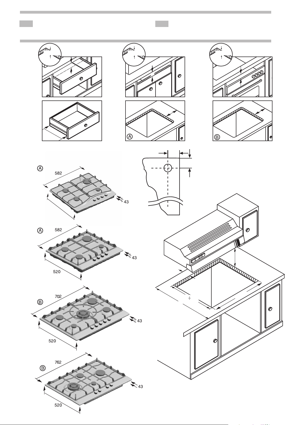
Fitting measurements
1 - Minimum distances (mm). Cut a gap of
the required size, Fig. 1.
If no oven is installed under an electrical or
mixed (gas and electric) hob, place a
separator of non-flammable material e.g.
plywood or metal at a distance of 10 mm.
from the bottom of the hob to prevent
access to the lower part of the hob.
If no oven is installed under a gas hob, it is
suggested to place a separator of nonflammable material e.g. plywood or metal at
a distance of 10 mm from the bottom of the
hob to prevent access to the lower part of
the hob.
In the event that a drawer is located beneath
the appliance, please make sure that the
drawer contains no heat-sensitive or easily
combustible objects, such as spray cans or
shoe polish. Use a heat-resistant utility
drawer only.
If the hob is to be installed above an oven,
check that the oven is fitted with power
ventilation, and check the dimensions
according to the assembly manual.
Centre the hob in the space provided in the
kitchen unit.
2 - The chipboard used to make the
worktops tends to swell quite quickly when
it comes into contact with moisture. Thus we
recommend treating the cut edges with a
special glue, to protect them from steam or
any condensation that might drip down
beneath the cooker unit’s work surface.
Depending on the model, the clips and the
watertight seal (lower edge of the hob) may
already be fitted; if this is the case, do not
remove them under any circumstance.
The seal ensures that the entire work
surface will be watertight, and prevents
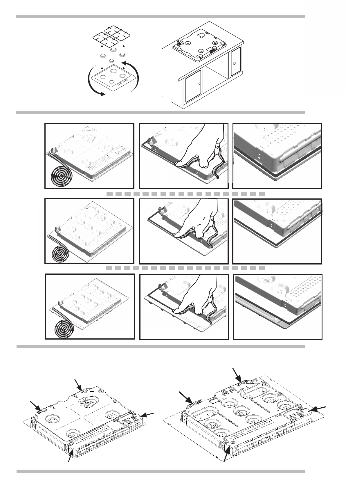
water seepage.
If this item has not been fitted in the factory,
remove the pan supports and the gas
burner covers and diffusers from your hob,
and turn it upside down. Fig. 2. Now fit the
adhesive seal supplied with the appliance
onto the lower edge of the hob. Fig. 3a/3b/
3c, remove the clips from the attached
accessories bag and screw them into the
lower points designed for this purpose,
Fig. 4.
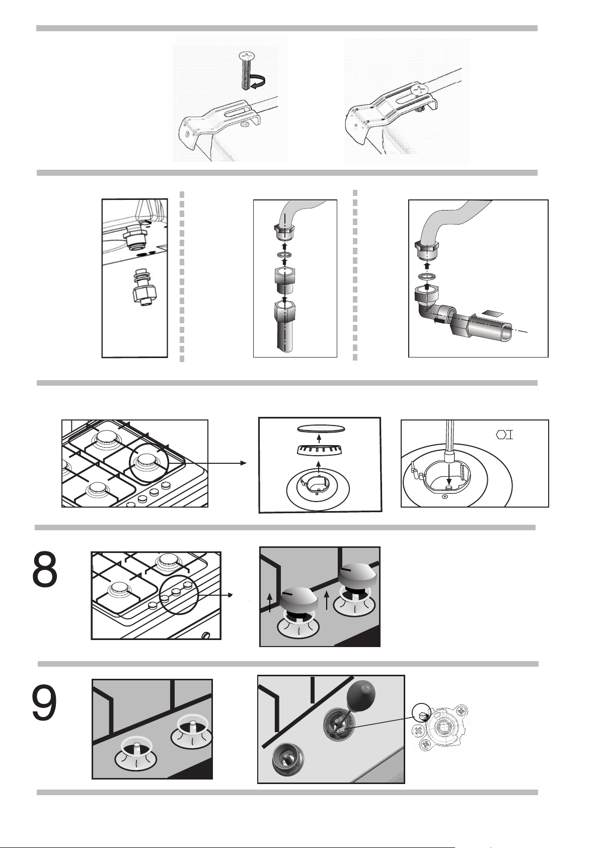
Press down all around the edge so that the
hob is supported along its entire perimeter,
turn the clip and tighten the screw as shown
in Fig. 5.
For disassembly, unscrew the clip and
proceed in the reverse manner.
3 - The end of the gas hob’s inlet collector
has a ½” (20.955 mm) elbow, Fig. 6. This
elbow allows for:
- A rigid connection, Fig. 6a.
- Connection using a flexible metal tube
(L min. 1 m - max. 3m). In this case, it is
necessary to install the accessory 427950
and the seal (034308) between the outlet
of the manifold and the gas supply, Fig. 6b.
With this option, you must prevent the pipe
from coming into contact with moving parts
of the insertion unit (for example, a drawer)
or access to any spaces which might
become obstructed. If you need to connect
the gas supply horizontally, our technical
services department can supply you with an
adaptor (code 173018) and a seal (code
034308), Fig. 6c.
The position of the gas pipe, relative to the
hole in the kitchen unit where it is to be fitted
is shown in Fig. 1b.
Make sure that all the connections that have
been installed are airtight. The manufacturer
does not accept any responsibility for leaks,
if the elbow is moved or turned; or for
connections carried out by the installation
technician.
4 - The following must be checked on the
specifications plate: the voltage and the
total power. This appliance must be earthed.
Always make certain that all connections
have been installed are in accordance with
national legal requirements. Observe all the
local electricity supply company
regulations.
In order to meet standard safety regulations,
the installation technician must provide an
omnipolar cut-off switch with a contact
separation of at least 3 mm. This is not
necessary if the connection is made via a
plug, so long as the user has access to it.
All appliances fitted with plugs should only
be connected to sockets which have been
correctly earthed.
This appliance is type “Y”, which means that
the supply cable MUST NOT BE REPLACED
BY THE USER; this can only be performed
by the manufacturer’s technical services
department. The cross section and cable
type must always be maintained.
Do not make any adjustments to the interior
of the appliance. If this should be
necessary, call our technical assistance
service.
Our hobs are supplied with a power cable
with or without a plug.
TYPES OF CABLES
Cooking hob: Power cable:
All gas 3 x 0.5 mm2
Electric hot plate 3 x 0.75 mm2
Electric hot plate 3 x 1 mm2
Changing gas type
All installation, regulation and adaptation to
other types of gas must be carried out by an
authorised installation technician, respecting
all applicable regulations, standards and the
country's electrical and gas supply
companies' specifications.
It is recommended that you call our
Technical Assistance Service for adaptation
to other types of gas. Before you begin, turn
off the appliance's electricity and gas supply.
Before connecting up the appliance to the
installation, first check that it has been
adjusted for the type of gas that is to be
supplied. Our hobs leave the factory set to
function with the type of gas that is indicated
on the specifications plate.
Provided that it is allowed by the current
laws in your country (see specifications
plate), this hob may be adapted to function
with other types of gas. To do so, carry out
the following:
A) Change the nozzles of the burners on the
hob.
1- Remove the pan supports, the tops and
the casing of the gas burner.
2- Change the nozzles using a 7 mm box
spanner (see table II) and make sure that
they are screwed in tightly to ensure that
they are airtight. Fig. 7.
With these burners the air does not have to
be adjusted.
B) Adjusting of the taps of the hob burners
for reduced consumption.
1- Turn the taps down to minimum.
2- Remove the control knobs from the taps.
Fig. 8.
3- It has a flexible rubber seal. Simply apply
pressure with the tip of the screwdriver to
release the thread toward the tap’s
adjusting screw. Fig. 9.
Do not remove the disc seal.
If you see the By-pass adjustment hole when
the remote control is removed, Fig. 10,
insert a screwdriver in the hole, Fig. 10a.
Otherwise remove the outer retainer.
4- Adjusting the by-pass screw (see table III).
- For propane and butane gas, the screw
must be screwed down tight.
- For natural gas, loosen the by-pass screw
until the burner is producing the desired gas
flow, in such as way that when you turn the
burner controls from maximum to minimum,
the flame does not go out, nor is there a
flame back draught created.
5- It is important that all the seals are
replaced so as to ensure that all
components are watertight in the event of
liquids being splashed onto the hob.
6- Replace the control knobs on the taps.
Do not dismantle the tap shaft (fig. 11): in
the event of a malfunction, change the
whole tap.
C) Stick on the sticker indicating that the
appliance’s gas supply has been changed
next to the specifications plate.
Page 6

it
Da mettere da parte e conservare
Ilstruzioni per l’installatore
Tutte le operazioni di installazione,
regolazione e adattamento a un diverso tipo
di gas devono essere effettuate da un tecnico
autorizzato, nel rispetto della normativa e
della legislazione applicabili, nonché delle
prescrizioni delle società locali di fornitura di
gas ed elettricità.
Per l'adattamento a un diverso tipo di gas, si
consiglia di rivolgersi al Servizio Tecnico.
Prima di effettuare qualsiasi operazione,
staccare l'alimentazione elettrica e chiudere il
gas dell'apparecchio.
Prima di collegare l’apparecchio
all’impianto, verificare che sia predisposto
per il tipo di gas che gli verrà fornito
(consultare la tabella I). I nostri piani di
cottura escono dalla fabbrica già pronti per
funzionare con il tipo di gas riportato sulla
targa d’identificazione.
È indispensable che il luogo in cui viene
installato l’apparecchio sia ventilato come
da normativa. I gas di combustione,
pertanto, devono essere evacuati
all’esterno.
Verificare le dimensioni del piano cottura,
nonché le dimensioni dell’apertura da
effettuare nel mobile.
I panelli che si trovano sul piano di lavoro,
nelle immediate vicinanze del piano cottura,
devono essere di un materiale non
infiammabile. Sia i rivestimenti stratificati sia
la colla che li fissa devono essere resistenti
al calore per evitare deterioramenti.
I cavi elettrici non devono essere a contatto
con zone di calore.
Il cavo di alimentazione deve essere fissato
al mobile per evitare che tocchi parti calde
del forno o del piano cottura.
Gli apparecchi con componenti elettrici
devono essere collegati obbligatoriamente a
terra.
Questo apparecchio deve essere installato
in base alle normative vigenti e solo ed
esclusivamente in un ambiente ben
ventilato.
Leggere attentamente le istruzioni prima di
procedere all’installazione e all’uso.
In caso di inosservanza delle disposizioni in
merito, le responsabilità ricadranno
sull’installatore, poiché in tal caso il
fabbricante declina qualsiasi responsabilità.
Inserimento del piano cottura
nel mobile
Questo apparecchio rientra nella classe 3
della norma EN 30-1-1 per gli apparecchi a
gas: apparecchio incassato in un mobile.
Misure di incasso
1 - Distanze minime (mm). Realizzare sul
piano di lavoro un taglio delle dimensioni
necessarie. Fig. 1.
Se non è installato nessum forno sotto un
piano cottura elettrico o misto (a gas ed
elettrico), situare un separatore di materiale
non infiammabile, p. es. in compensato o in
metallo, ad una distanza di 10 mm dalla
base del piano cottura per evitare il contatto
con la parte inferiore dello stesso.
Se non è installato nessun forno sotto un
piano cottura a gas, si suggerisce di situare
un separatore di materiale non infiammabile,
p. es. in compensato o in metallo, ad una
distanza di 10 mm dalla base del piano
cottura per evitare il contatto con la parte
inferiore dello stesso.
Nel caso in cui sia situata una base di
assemblaggio al si sotto dell’apparecchio, si
prega di assicurarsi che la base non
contenga oggetti facilmente infiammabili o
termosensibili, come recipienti spray o
prodotti per la pulizia delle scarpe. Usare
solo utensili resistenti al fuoco per la base di
assemblaggio.
Per l’installazione su un forno, verificare che
quest’ultimo abbia una ventilazione forzata e
controllare le dimensioni confrontandole con
il manuale di montaggio.
Centrare il piano cottura nel relativo vano
cieco d’incasso nel mobile.
2 - Le fibre di legno utilizzate per la
fabbricazione dei mobili del piano cottura,
poiché entrano a contatto con l’umidità, si
gonfiano con relativa rapidità. È pertanto
opportuno stendere una colla speciale sulle
superfici di taglio, per proteggerle del
vapore o dalla condensa che potrebbe
accumularsi sotto il piano di lavoro del
mobile da cucina.
A seconda dei modelli, i morsetti e la
guarnizione di tenuta (bordo inferiore del
piano cottura) possono essere stati già
collocati in fabbrica; in tal caso, non
rimuoverli per nessun motivo. La guarnizione
garantisce l’impermeabilizzazione di tutta la
superficie di lavoro ed evita qualsiasi
infiltrazione.
Se non è già stata applicata in fabbrica,
togliere le griglie, i coperchi dei fornelli e i
diffusori del piano cottura e capovolgerlo,
Fig. 2, collocare la guarnizione autoadesiva
in dotazione con l’apparecchio sul bordo
inferiore del piano cottura, Fig. 3a/3b/3c,
prendere i del piano morsetti dal sacchetto
degli accesori in dotazione e collocarli negli
appositi fori inferiori, Fig. 4.
Fare pressione contemporaneamente sugli
estremi in modo che il piano cottura poggi
lungo tutto il suo perimetro, girare i morsetti
fino a che non afferrano il mobile ed avvitare,
Fig. 5.
Se fosse necessario smontarlo, seguire il
procedimento inverso.
3 - L’estremità del collettore di ingresso del
gas del piano cottura è fornito di un racord
di 1/2”(20,955 mm), Fig. 6. Tale racord
permette:
- Il racordo rigido, Fig. 6a.
- L’attacco ad un tubo flessibile metallico
(L min. 1m - max. 3m). In questo caso è
necessario intercalare l’accessorio 427950
e la guarnizione di tenuta (034308) forniti,
fra l'uscita del collettore e l’attacco del
gas, Fig. 6b.
In questo caso si deve evitare il contatto di
questo tubo con parti mobili dell’unità a
incasso (ad esempio un cassetto) e il
passaggio attraverso spazi che potrebbero
essere ostruiti.
Qualora fosse necessario realizzare l’atacco
del gas in orizzontale, il nostro servizio
tecnico dispone di un gomito, con il codice
173018, più una guarnizione con il codice
034308, Fig 6c.
La posizione del tubo collettore rispetto al
vano d’incasso è quella rappresentata nella
Fig. 1b.
Assicurarsi della tenuta di tutti gli attacchi
realizzati. Il fabbricante declina qualsiasi
responsabilità su fughe se si muove o si gira
il raccordo a gomito, e non è responsabile
degli attacchi realizzati dall’installatore.
4 - Sulla targa d’identificazione si deve
verificare: la tensione e la potenza totali.
L’apparecchio deve essere collegato a terra.
Accertarsi che l’attacco sia stato effettuato
nel rispetto delle disposizioni di legge vigenti
nel paese in cui l’apparecchio viene
installato.
Rispettare integralmente le disposizioni
della compagnia elettrica locale.
Per rispettare le disposizioni di sicurezza
abituali, l’installatore deve prevedere un
interruttore onnipolare con una distanza di
apertura dei contatti di almeno 3 mm.
Questo non è necessario in caso di
connessione attraverso una spina, a
condizione che l’utente possa accedere a
quest’ultima agevolmente.
Gli apparecchi muniti di spina devono
essere collegati soltanto a cassette con
presa di terra debitamente installata.
L’apparecchio è di tipo “Y“, cioè il cavo
d’ingresso NON PUÒ ESSERE SOSTITUITO
DALL’UTENTE ma soltanto dal servizio
tecnico della casa. Rispettare la sezione e il
tipo di cavo.
Non manipolare l’apparecchio al suo
interno.
In caso di necessità, chiamare il nostro
servizio di assistenza tecnica.
I piani cottura vengono forniti con un cavo di
alimentazione con o senza spina.
TIPI DI CAVI
Piano cottura Cavo di alimentazione:
Tutto gas 3 x 0,5 mm2
Piastra elettrica 3 x 0,75 m
Piastra elettrica 3 x 1 mm2
m2
Modifica del tipo di gas
Tutte le operazioni di installazione,
regolazione e adattamento a un diverso tipo
di gas devono essere effettuate da un tecnico
autorizzato, nel rispetto della normativa e
della legislazione applicabili, nonché delle
prescrizioni delle società locali di fornitura di
gas ed elettricità.
Per l'adattamento a un diverso tipo di gas, si
consiglia di rivolgersi al Servizio Tecnico.
Prima di effettuare qualsiasi operazione,
staccare l'alimentazione elettrica e chiudere il
gas dell'apparecchio.
Prima di collegare l’apparecchio
all’impianto, verificare che sia predisposto
per il tipo di gas che gli verrà fornito. I nostri
piani di cottura escono dalla fabbrica già
pronti per funzionare con il tipo di gas
riportato sulla targa d’identificazione.
Nella misura in cui lo consente la
regolamentazione vigente nel vostro paese
(cfr. targa d’identificazione), questo piano
cottura può essere adattato al
funzionamento con altri gas. A tale scopo si
devono effettuare le seguenti operazioni:
A) Sostituzione degli iniettori dei bruciatori
del piano cottura.
1- Togliere le griglie, i coperchi e il corpo del
bruciatore.
2- Sostituire gli iniettori usando una chiave a
tubo di 7 mm (consultare la tabella II) e
accertarsi di stringere a fondo per garantire
la tenuta, Fig 7. In questi bruciatori non è
necessario effettuare la regolazione dell’aria
primaria.
B) Regolazione del consumo ridotto delle
manopole dei bruciatori del piano cottura.
1- Collocare le manopole sul minimo.
2- Togliere le manopole, Fig. 8.
3- Si trovera un dispositivo in gomma
flessibile. Basta premere con la punta del
cacciavite per poter accedere alla vite di
regolazione della chiave, Fig. 9.
Non smontare mai la tenuta.
Qualora, estraendo la manopola, si veda il
foro di regolazione del by-pass, Fig 10,
inserire un cacciavite nell’orifizio, Fig. 10a; in
caso contrario, smontare la piastra esterna.
4- Regolazione della vite by-pass
(consultare la tabella III).
- Per gas propano e butano, la vite deve
essere premuta a fondo.
- Per il gas naturale, allentare la vite fino a
che il gas non esce bene dal bruciatore, in
modo tale che quando il bruciatorie passa
dalla posizione massima alla minima, non si
spegna né si crei alcun ritorno di fiamma.
5- È importante che siano collocate tutte le
tenute per poter garantire la tenuta elettrica,
contro i versamenti di liquidi del piano
cottura.
6- Collocare nuovamente le manopole.
Non smontare mai l’asse della manopola
(fig. 11): in caso di guasto, sostituire la
chiave completa.
C) Applicare l’etichetta che indica il gas al
quale è passato l’apparecchio vicino alla
targa d’identificazione.
Page 7

I
G20 (m3/h) G30 (g/h) G31 (g/h) W V~ Hz
∑Qn (kW)
PCK755DIT HSE-7FB3W30 9,35 0,891 679 667 0,6 W 230 V~ 50 Hz
PCD655MIT HSE-6FB4030 7,50 0,715 544 535 0,6 W 230 V~ 50 Hz
PCL752FIT HSE-7FB4W30 11,10 1,058 806 792 0,6 W 230 V~ 50 Hz
PCK755MIT HSE-7FB3W30 9,35 0,891 679 667 0,6 W 230 V~ 50 Hz
PCL755FIT HSE-7FB4W30 11,10 1,058 806 792 0,6 W 230 V~ 50 Hz
PCL755DIT HSE-7FB4W30 11,10 1,058 806 792 0,6 W 230 V~ 50 Hz
PCL765DIT HSE-7FB4W30 11,10 1,058 806 792 0,6 W 230 V~ 50 Hz
PCL755MIT HSE-7FB4W30 11,10 1,058 806 792 0,6 W 230 V~ 50 Hz
PCI815B80J HSE-7FB3W30 9,35 0,891 679 667 0,6 W 230 V~ 50 Hz
PCI815M90J HSE-7FB3W30 9,35 0,891 679 667 0,6 W 230 V~ 50 Hz
COUNTRIES/GASES GAS ADJUSTED MODEL TYPE
G-20/20 mbar ERDGAS / ERDGAS E /
NATURGAS / GAS NATURAL /
MAAKAASU NATURGAS / Φυοικ_αεοιο /
NATURAL GAS / GAS METANO / GAS
NATUREL / GAZ ZIEMNY
G-20/G-25-20/25 mbar AARDGAS / GAZ
IT/PT
2H3+
II
20-28/37
ES/GB/GR/IE
2E
20
LU
I
2E+3+
BE/FR
II
CZ/SK/EE/LT/SI/RO/BG
20/25-28-30/37
DE
2H
20
I
AT
DK/FI/SE/LV
Cat.
P(mbar)
2H3+
II
20-30/37
2H3B/P
20-30
II
20-50
2ELL3B/P
II
20-50
2H3B/P
II
Cat.
P(mbar)
NATUREL LACQ
G-20/20 mbar ERDGAS / ERDGAS E /
NATURGAS / GAS NATURAL /
MAAKAASU NATURGAS / Φυοικ_αεοιο /
2H
LV
I
2H3+
IT/PT
II
2E
LU
I
2E+3+
BE/FR
II
AT
2H3B/P
II
Cat.
NATURAL GAS / GAS METANO / GAS
NATUREL / GAZ ZIEMNY
G-20/G-25-20/25 mbar AARDGAS / GAZ
NATUREL LACQ
20
2H3+
II
20-28/37
ES/GB/GR/IE
20-30/37
DE
20-50
20
2ELL3B/P
II
20/25-28-30/37
20-30
2H3B/P
II
20-50
DK/FI/SE/CZ/SK/EE/LT/SI/RO/BG
P(mbar)
Cat.
P(mbar)
Page 8

II
GAS mbar Qn (Kw) m3/h g/h Qr (kW)
G20 20 72 1,00 0,095 - 27 0,33
G30 29 50 1,00 - 73 27 0,33
G31 37 50 1,00 - 71 27 0,33
G20 20 115 3 0,286 G30 29 85 3 - 218
G31 37 85 3 - 214
G20 20 100 1,75 0,167 G30 29 67 1,75 - 127
G31 37 67 1,75 - 125
G20 20
G30 29
G31 37
G20 20
G30 29
G31 37
140 3,60
97 3,60
97 3,60
115 2,50
78 2,30
78 2,30
0,343
- 261
- 257
0,238
- 167
- 164
39
39
39
30
30
30
- 53 1,26
53 1,26
53 1,26
- 53 1,26
53 1,26
53 1,26
0,5
0,6
0,6
0,35
0,41
0,41
Cod. 9000143114 E
 Loading...