

Bosch Multi-Detector DMD4 Operating/safety Instructions Manual
IMPORTANT: IMPORTANT : IMPORTANTE:
Read Before Using Lire avant usage Leer antes de usar
Operating/Safety Instructions
Consignes de fonctionnement/sécurité
Instrucciones de funcionamiento y seguridad
DMD4
For English Version
Version française
Versión en español
See page 2 Voir page 12 Ver la página 22
1-877-BOSCH99 (1-877-267-2499) www.boschtools.com
Call Toll Free for
Consumer Information
& Service Locations
Pour obtenir des informations
et les adresses de nos centres
de service après-vente,
appelez ce numéro gratuit
Llame gratis para
obtener información
para el consumidor y
ubicaciones de servicio
BM 2609140574 08-08 9/3/08 8:40 AM Page 1
-2-
k
1
2
3
4
5
6
7
j
i
h
g
a
b
c
d
e
f
8
9
10
8
11
12
FIG. 1 FIG. 3
FIG. 2
BM 2609140574 08-08 9/3/08 8:40 AM Page 2

-3-
The multi-detector’s ability to detect objects
is affected by the proximity of other equipment
that produce strong magnetic or
electromagnetic fields, and by moisture,
metallic building materials, foil-laminated
insulation materials and/or conductive
wallpaper.
The multi-detector’s ability to detect wood
substructures (studs) is also affected by
inconsistency on the thickness of the surface
material, such as plaster and lath.
It is possible that there may be metal, wood or
wiring or something else, such as plastic
pipes, beneath the scanned surface that is not
detected.
The detector alone should
not be relied on exclusively
to locate items below the scanned surface.
Use other information sources to help locate
items before penetrating the surface. Such
additional sources include construction plans,
visible points of entry of pipes and wiring into
walls, such as in a basement, and standard
16” and 24” stud spacing practices.
Before penetrating a
surface (such as with a
drill, router, saw or nail), always shut off
the electrical power, gas and water
supplies.
Cutting, drilling, etc… into these
items when operational can result in personal
injury.
Optimal operation of the multi-detector is possible only when the operating instructions
and information are read completely, and the instructions contained therein are strictly
followed.
SAVE THESE INSTRUCTIONS
Functional Description
INTENDED USE
The multi-detector is intended for the detection
of metals (ferrous and non-ferrous metals,
such as pipes, metal studs and rebar), wood
studs and joists, and “live” wires/conductors in
walls, ceilings and floors.
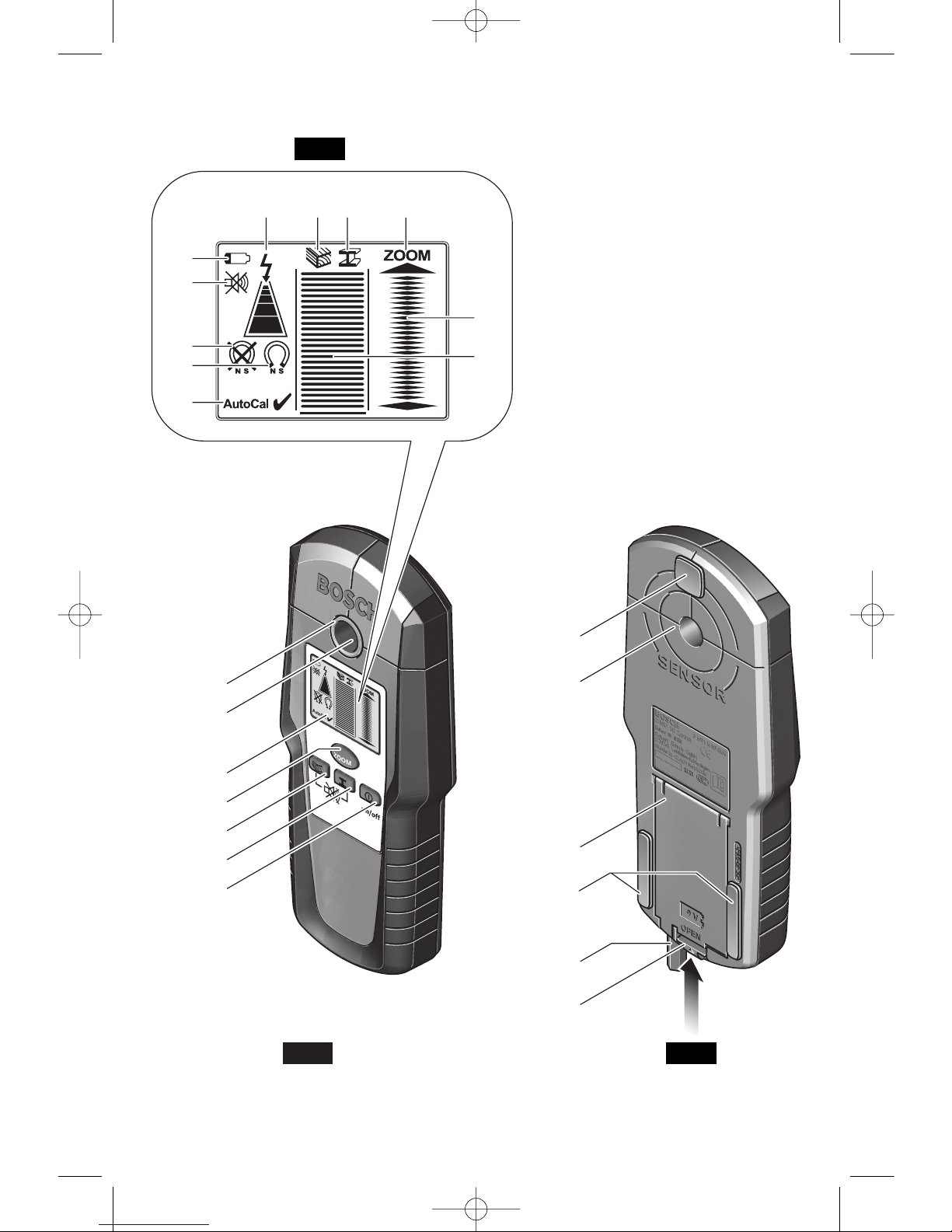
PRODUCT FEATURES
The numbering of the product features shown
refers to the illustration of the multi-detector on
the graphic page 2.
1 Illuminated ring
2 Marking hole
3 Display
4 Metal mode “ZOOM” button (also used for
wood calibration)
5 Wood detection mode button
6 Metal detection mode button
7 “On/off” button
8 Felt pads
9 Sensor area
10 Battery lid
11 Pencil for marking (removable)
12 Latch of battery lid
DISPLAY ELEMENTS
a
“Live” wire indicator
b Wood detection mode indicator
c Metal detection mode indicator
d
“ZOOM”
indicator
e “ZOOM” measuring indicator
f Main measuring indicator
g “AutoCal” calibration indicator
h Magnetic metal indicator
i Non-magnetic metal indicator
j Switched-off audio signal indicator
k Battery indicator
Safety Rules for Multi-Detector
Read all instructions. Failure to follow all instructions listed below may
result in electric shock, fire and/or serious injury.
SAVE THESE INSTRUCTIONS
!
WARNING
!
WARNING
!
WARNING
BM 2609140574 08-08 9/3/08 8:40 AM Page 3

Preparation
-4-
DIGITAL MULTI-DETECTOR DMD4
Article number 3 601 K10 010
Maximum scanning depth*:
Ferrous metals 4" / 100 mm
Non-ferrous metals (copper) 3-1/8" / 80 mm
Copper wiring (live) 2" / 50 mm
Wood Substructures (studs) 3/4" / 20 mm
Automatic switch-off After approx. 5 min
Operating temperature 14 °F 122 °F
–10 °C +50 °C
Storage temperature – 4 °F –158 °F
–20 °C +70 °C
Battery 1 x 9 V 6LR61
Rechargeable battery 1 x 9 V 6F22
Operating lifetime (alkali-manganese batteries) Approx. 6 h
Weight according to EPTA-Procedure 01/2003 0.53 lbs/ 0.24 kg
* Depends on material and size of objects as well as material and condition of structure.
** Less scanning depth for wires/conductors that are not “live”.
Please observe the article number on the type plate of your multi-detector.
Technical Data
INSERTING/REPLACING THE BATTERY
Use only alkali-manganese or rechargeable
batteries.
To open the battery lid
10, press the latch 12
in the direction of the arrow and fold up the
battery lid. Insert the supplied battery. Pay
attention that the polarity is correct, according
to the + and - symbols on the inside of the
battery lid.
• When the battery indication
k in the display
lights up, measuring is possible for approx. 1
h when using alkali-manganese batteries
(service life is shorter with rechargeable
batteries).
• When the battery indication
k flashes,
measuring is still possible for approx. 10
minutes.
• When the battery indication k and the
illuminated ring
1 (red) are flashing,
measuring is no longer possible and the
battery or the rechargeable battery
respectively, must be replaced.
•
If the multi-detector is not used for a long
period of time, the battery must be
removed.
The battery can corrode or
discharge itself over long periods.
BM 2609140574 08-08 9/3/08 8:40 AM Page 4

-5-
Operating Instructions
SWITCHING ON
Before switching the multi-detector on, make
sure that the sensor area 9 is not moist.
If
required, wipe the multi-detector dry using a cloth.
The multi-detector detects objects that are
below the sensor area
9.
If the multi-detector was subject to an
extreme temperature change, allow it to
adjust to the ambient temperature before
switching on.
To switch the multi-detector on, press any button.
• When switching the multi-detector on with
the wood detection mode button
5 or with the
metal-detection mode button
6, it will
automatically be in the respective detection
mode. After a brief self-check, the multidetector is ready for operation.
• When switching the multi-detector on with
the “on/off” button
7 or with the “ZOOM”
button 4, it will be in the detection mode last
used. After a brief self-check, the multidetector is ready for operation.
• When the multi-detector is in the metal-
detection mode, the service readiness is
indicated through a check mark behind the
“AutoCal” calibration indicator g.
RECOMMENDATIONS FOR
PROPER SCANNING
• Avoid wearing jewelry such as rings or
watches when using the detector. The metal
may cause inaccurate detection.
• Move the multi-detector uniformly the surface
without lifting it off or changing the applied
pressure.
• During the scan, all three of felt pads
8 must
always have contact with the surface.
• Make sure that your fingers of the hand
holding the multi-detector do not touch the
surface being scanned, which could interfere
with the tool’s ability to effectively detect
items below the surface.
• Do not touch the surface being scanned with
your other hand or any other part of part of
your body, because the moisture may affect
the scanning.
• Always measure SLOWLY to achieve
maximum sensitivity.
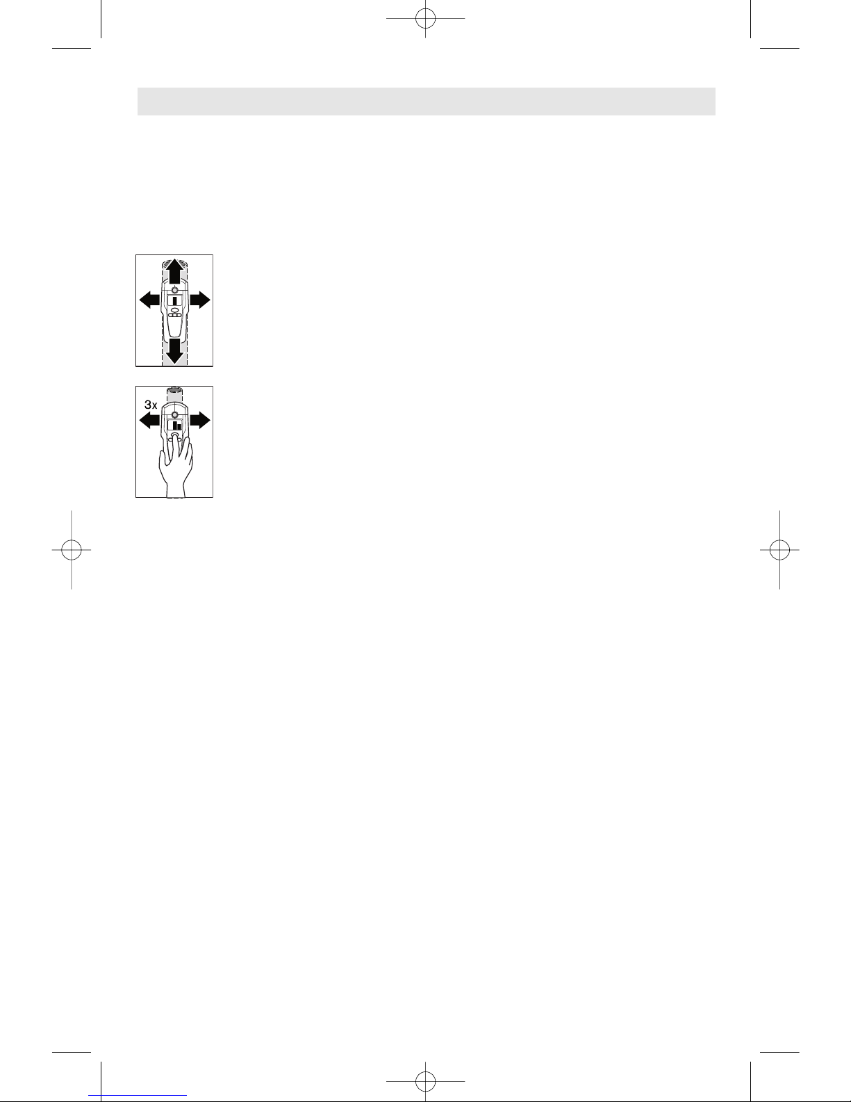
MARKING OBJECTS
Detected objects can be marked as required.
For this, remove the pencil
11 from the multi-
detector and carry out the scan as usual.
Once you have found the limits or the center
of an object, simply mark the sought after
location through the marking opening
2. It is a
good idea to establish a consistent practice of
making one type of mark over places in which
you
do not want to penetrate (drill, nail, cut),
such as O, and a different symbol over places in
which you do want to penetrate, such as an X.
SWITCHING OFF
To switch the multi-detector off, press the
“on/off” button
7.
• If none of the multi-detector buttons are
pressed for approx. 5 minutes, the multidetector switches off automatically in order to
extend the service life of the battery.
SWITCHING OFF THE SIGNAL TONE
The signal tone can be switched on and off.
For this, press the metal-detection mode
button
6 and the wood-detection mode button
5 at the same time. When the signal tone is
switched off, the switched-off audio signal
indicator j appears on the display. The signal
tone setting is maintained after switching the
multi-detector off and on again.
BM 2609140574 08-08 9/3/08 8:40 AM Page 5
-6-
PRELIMINARY METAL SCAN
When scanning for metal objects, press the
metal detection mode button
6. The metal
detection mode indicator
c is indicated in the
display and the illuminated ring
1 lights up green.
Position the multi-detector then move it
uniformly across the surface.
• When the multi-detector
comes close to a metal object,
then the amplitude increases,
as represented by the number
of bars shown in the main
measuring indicator
f.
• When it moves away from the
object, the amplitude and
number of bars shown
decreases.
At the position of maximum
amplitude, the metal object is
located below the center of the
sensor (below the marking
opening
2).
As long as the multi-detector is above the
metal object, the illuminated ring
1 lights up
red and a steady tone sounds.
Notes:
• The ability to detect nails, screws, rebar and
other metal objects is somewhat dependent
on their orientation. For example, at any
given depth it is easier for the unit to detect
the length of a screw or nail than it is to
detect the end of a screw or nail.
• The entire width (3-1/8” / 8 cm) of the detector
can detect metal near the surface of scanned
items, so the unit is wide enough to scan for
metal near the surface of a 3” wide board prior
to sanding or planing.
• When a metal item is much narrower than
the SENSOR area, the maximum signal
might be displayed when the item is just
under the left and right of the center hole,
rather than the center of the hole, especially
if the item is near the surface.
• Always measure SLOWLY to achieve
maximum accuracy and sensitivity
• Use the ZOOM feature to maximize
sensitivity, especially important when
searching for deep items prior to drilling,
sawing, nailing and/or routing.
ZOOM METAL SCAN
The ZOOM mode should be used AFTER the
Preliminary Metal Scan for the purposes listed
below.
• ALWAYS start the ZOOM Metal Scan near
the location that the metal object was
detected in the Preliminary Metal Scan.
• Press the “ZOOM” button
4 and KEEP IT
PRESSED while continuing to move the
multi-detector over the area. Observe only
the ZOOM measuring indicator
e.
Precision Location
- The ZOOM function can
be used to more-precisely locate the center of
a metal object and for distinguishing between
close metal objects. The “ZOOM” measuring
indicator e has the greatest amplitude over the
center of the metal object.
Detection of Small or Deep Objects - The
ZOOM function can also be used when very
small or deeply embedded metal objects are
being detected but the main measuring
indicator
f does not react.
Detection Though Material With Metal
inclusions
- The ZOOM function can also be
used if there are any metal inclusions in the
material being scanned, such as wire mesh in
lath and plaster walls, then a continuous
signal is indicated in the main measuring
indicator
f.
MAGNETIC VS. NON-MAGNETIC METALS
If the metal object found is a magnetic (e.g.
iron or steel), then the indicator for magnetic
metals
h is displayed.
For non-magnetic metals, the indicator for
non-magnetic metals
i is displayed.
In order for the multi-detector to differentiate
between the metal types, it must be positioned
above the detected metal object and the
detection must be strong enough that the
illuminated ring
1 lights up red.
For weak signals, the indication of the metal
type is not possible. For steel wire mesh and
similar reinforcements in the scanned
structural material, amplitude of the main
measuring indicator
f is displayed over the
complete surface. In this case, always use the
“ZOOM” function for the scan. When scanning
over steel mesh in concrete, typically (but not
always) the indicator for magnetic metals
h is
displayed directly above the rebar; the
indicator for non-magnetic metals
i is
displayed between the rebars.
Scanning in Metal-Detection Mode
BM 2609140574 08-08 9/3/08 8:40 AM Page 6
-7-
Scanning in Wood-Detection Mode
The wood-detection mode actually detects
more than just wood substructures (studs and
joists). It may also detect metal and other
dense materials such as water-filled pipes
plastic pipes near the back of the surface in
the wall or ceiling. To help identify wood
substructures, first conduct a metal scan and
mark the location of any detected metal items.
Then conduct a scan in the wood-detection
mode. Items that are detected in the wooddetection mode but not in the metal-detection
mode are items that are possibly wood
substructures.
To scan for wood objects,
1. Press the wood detection mode button 5.
• The wood mode indicator
b and the
“ZOOM” indicator d are shown in the
display, the arrow below the
“ZOOM”
indicator d flashes, and the “AutoCal”
calibration indicator g and the illuminated
ring
1 go out.
2. Position the multi-detector onto the surface
to be scanned.
3. Then press the “ZOOM” button* 4 AND
KEEP IT PRESSED.
• Now the illuminated ring 1 lights up green,
the
AutoCal” calibration indicator g is
displayed again, and the
“ZOOM” indicator
d as well as the arrow below it go out, all
indicating that the multi-detector is calibrated
for the wood scan.
4. After the multi-detector has
been calibrated and while
continuing to press the
“ZOOM” button 4, move the
multi-detector uniformly over
the surface without lifting it off
or changing the applied
pressure. During the scan, the
felt pads
8 must always have contact with the
surface.
• When an object is detected, an amplitude is
displayed in the main measuring indicator
f.
Move the multi-detector over the surface
repeatedly to locate the object more
precisely. After moving over the same area
several times, the object can be indicated
quite accurately: The illuminated ring
1 lights
up red and a steady tone sounds as long as
the multi-detector is over the object. The
main measuring indicator
f has the greatest
amplitude (as represented by the number of
bars shown in the main measuring indicator
f )
over the center of the object.
Note: While the “ZOOM” button 4 is pressed
during the wood scan, the “ZOOM” feature
and ZOOM measuring indicator
e are inactive.
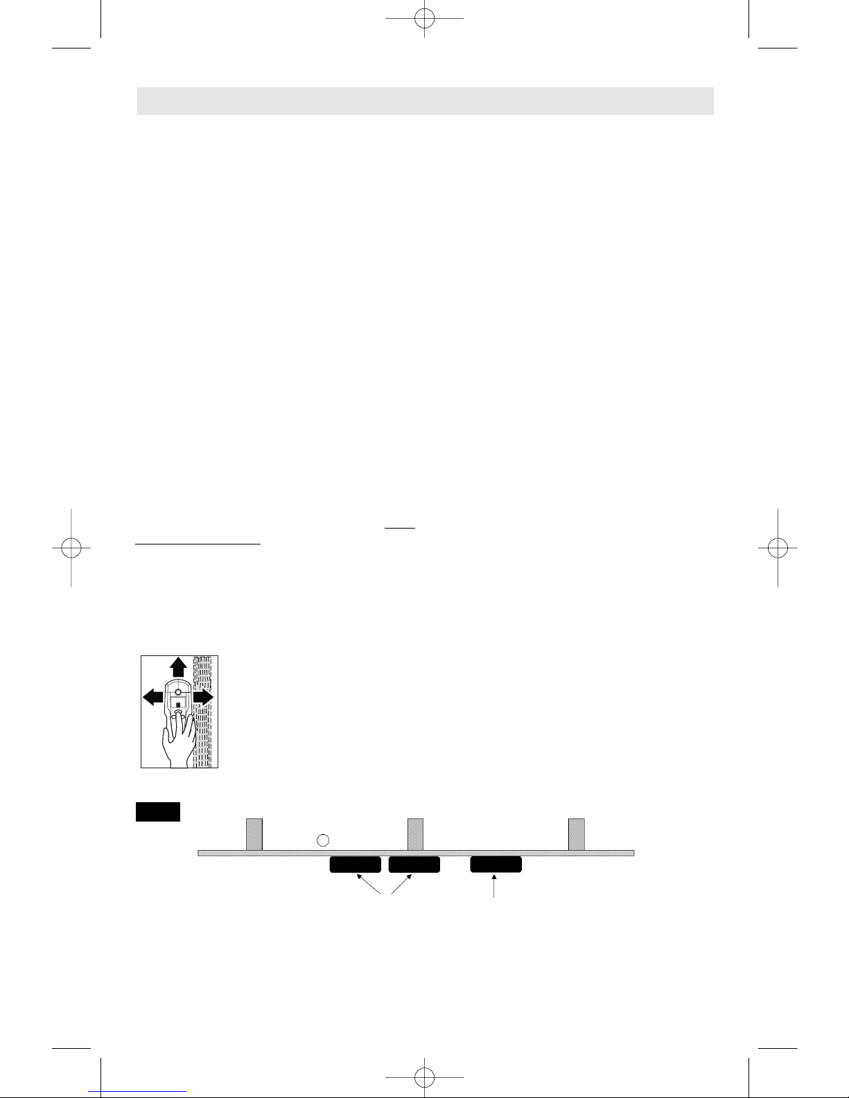
Notes:
• If the scan (and thus calibration) starts
over a dense object, such as a stud or a
pipe, and is then moved across the
surface
, the main measuring indicator f and
the arrow below the “ZOOM” function
indicator
d flash and the illuminated ring 1
flashes red, indicating a calibration failure. If
this happens, move the detector horizontally
to a different location and start the scan
again (Fig. 4).
•
During a wood scan, metal objects at
depths between 3/4" and 2" may also be
detected.
To help distinguish between
wood and metal objects, switch to metaldetection mode (see “Detecting Metal
Objects”). When an object is indicated at the
same location in the metal-detection mode,
then it is likely a metal object or a wood stud
or joist with nails or screws in it. To continue
searching for wood objects, switch back to
the wood-detection mode.
PIPE
STUD
STUD
STUD
MULTI-DETECTOR
AT PROBLEM
LOCATIONS FOR
STARTING
“WOOD” SCAN
MULTI-DETECTOR
AT GOOD
LOCATIONS FOR
STARTING
“WOOD” SCAN
WALL
FIG. 4
BM 2609140574 08-08 9/3/08 8:40 AM Page 7
-8-
Lath and Plaster
Because of the uneven thickness of the
plaster, it is difficult to detect wood studs using
the wood detection mode. It will probably be
easier to locate the studs by changing to the
metal-detection mode to locate the nails that
hold the lath to the studs.
Lath and Plaster with Metal Mesh
Reinforcement
(See SCANNING IN METAL–DETECTION
MODE).
Textured or Acoustic Walls and Ceilings
When scanning a wall or ceiling with an
uneven surface, place thin cardboard on the
surface to be scanned and scan over the
cardboard. In wood-detection mode, calibrate
with cardboard in place.
Wallpaper
If paper contains metallic foil, metallic fibers,
see SCANNING IN METAL-DETECTION
MODE. If paper is wet, it must be allowed to
dry before scanning.
Wood Flooring, Wood Subflooring and
Drywall Over Plywood Sheathing
Because of the thickness of these materials, it
is difficult to detect wood joists or studs using
the wood-detection mode. It will probably be
easier to locate these items by changing to the
metal-detection mode to locate the nails that
hold the materials to the joists or studs.
Carpeting
The DMD4 cannot detect wood studs and
joists through carpeting. It might be possible to
use the metal-detection mode to locate nails
or screws that were used to attach the wood
floor to the joist.
The multi-detector can indicate “live”
wires/conductors with 50 or 60 Hz of 120V AC
or at higher voltages. If other wires/conductors
are detected, they are indicated only as metal
objects. “The multi-detector automatically
scans for “live” wires/conductors in both the
metal mode and wood mode.
When a “live” wire/conductor is detected, the
indicator
a appears in the display. Move the
multi-detector over the surface repeatedly in
order to locate the “live” wire/conductor more
precisely. After moving the multi-detector over
the surface several times, the “live”
wire/conductor can be located quite precisely.
If the multi-detector is very close to the
wire/conductor (four or five bars in indicator a),
the illuminated ring
1 flashes red and the
signal tone sounds with a rapid tone
sequence.
• “Live” wires/conductors can be detected
more-easily when power consumers (e.g.,
lamps, appliances) are connected to the
wire/conductor being sought and switched
on.
• Wires/conductors with 110 V, 240 V and
380 V (three-phase current) are detected
with about the same scan capacity.
• Under certain conditions (such as when
behind metal surfaces, shielded in conduit or
behind surfaces with high water content),
“live” wires/conductors cannot be detected
with certainty. These ranges may be
recognized in the metal detection mode as
metal objects.
• Wires that are not “live” might be detected as
metal objects with the metal-detection mode.
However, unlike solid copper cables,
stranded copper cables are not detectable.
• When “live” wiring is detected over a wide
area, the scan for “live” wiring is not reliable
because something in the surface material is
shielding or distorting the electrical field.
Before penetrating a
surface (such as with a
drill, router, saw or nail), always shut off
the electrical power, gas and water
supplies.
Cutting, drilling, etc… into these
items when operational can result in personal
injury.
Scanning for “Live” Wires
Detection Through Special Surface Materials
!
WARNING
BM 2609140574 08-08 9/3/08 8:40 AM Page 8
-9-
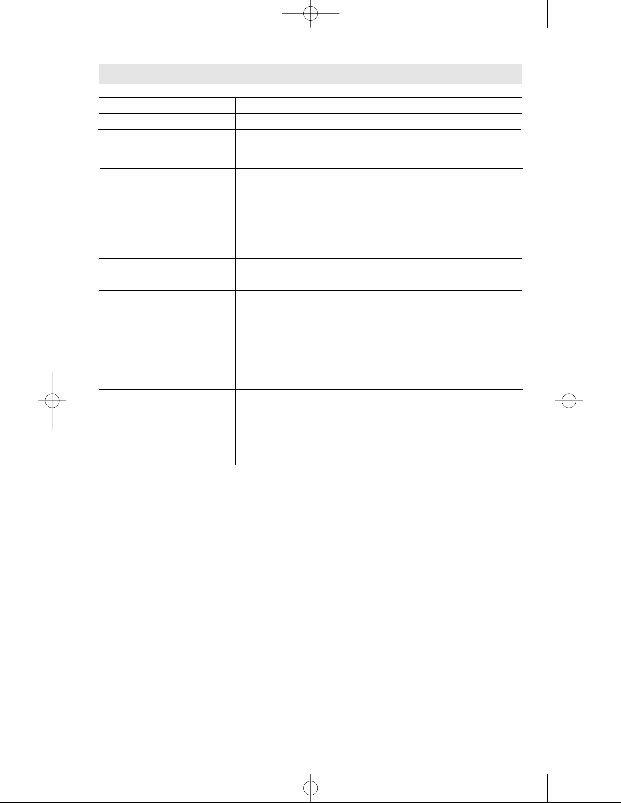
Metal Scan
Issue Possible Reason Remedy
Image of metal object • DMD4's metal detection • Use ZOOM feature to more
appears wider than actual is very sensitive. precisely determine location
size. and center of metal object(s).
Difficulty detecting metal. • Metal objects are too • Use ZOOM feature
deep. (See Maximun
• Scan in vertical direction as
Scanning Depth, page 4.)
well as horizontal direction.
Seemingly false metal • Jewelry or mechanical • Remove jewelry
detection. pencil are too close to
• Use non-mechanical pencil
SENSOR area.
• Recalibrate detector.
Wood Scan
Issue Possible Reason Remedy
Difficult detecting wood • Studs and joists are • Change to metal scan to search
studs and joists. too deep. for nails or screws that may
indicate location of the stud
or joist.
Difficult to successfully • Double and triple studs • Start scan farther away so
starting scan near doors are usually found around that outer edge of multiple
and/or windows. doors and windows. studs and /or headers are
detected.
More items than anticipated • Wood scan detects • Conduct metal scan as well
are detected. metal and other dense to help determine which
objects as well as studs detected items are metal,
and joists. rather than something else,
such as wood studs or
plastic pipes.
Trouble Shooting
BM 2609140574 08-08 9/3/08 8:40 AM Page 9
-10-
Maintenance and Service
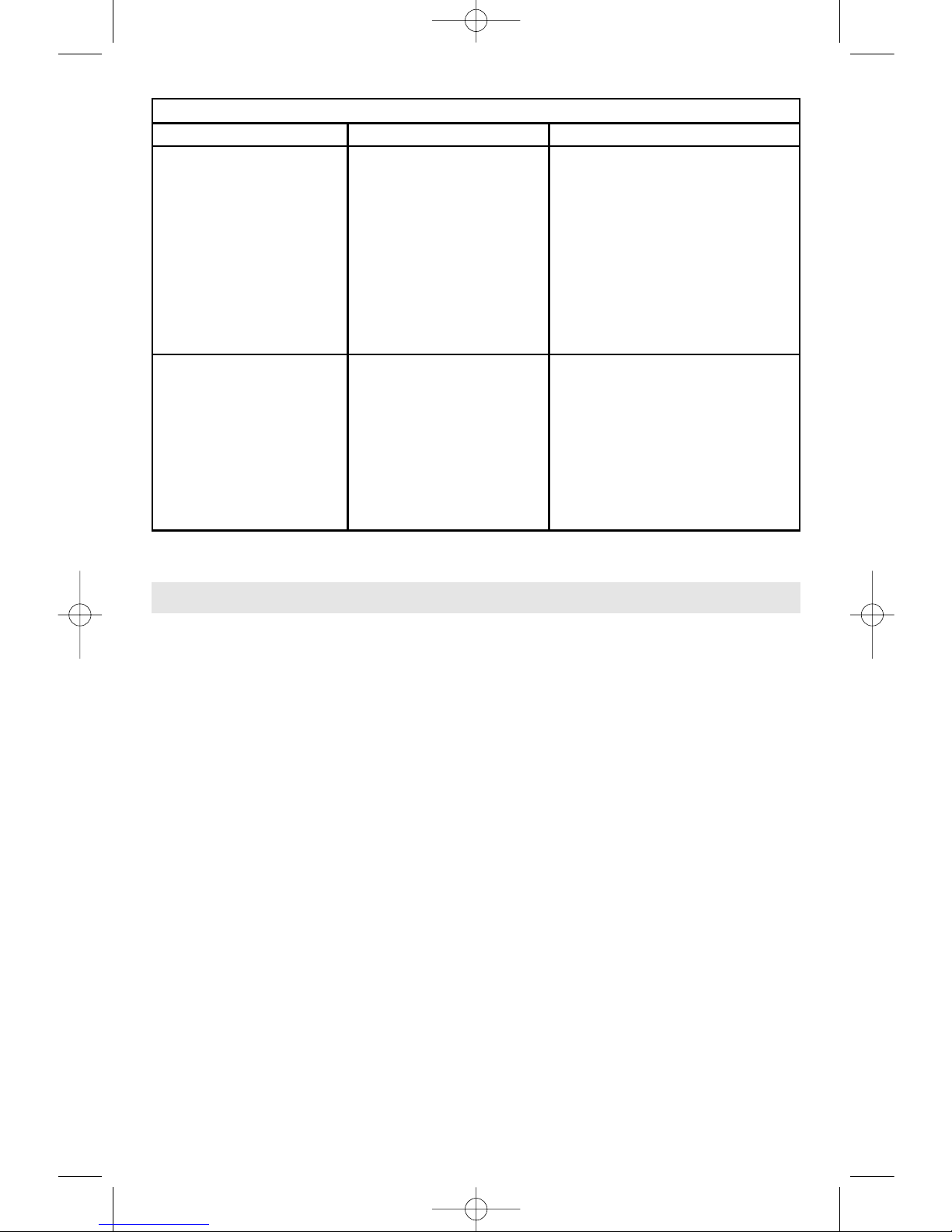
Detection of Electrical Wiring
Issue Possible Reason Remedy
Area of voltage appears
much larger than actual
electrical wire.
• Static charge may be
present on drywall,
spreading voltage as
much as 12 inches (305
mm) on either side of an
actual electrical wire.
• It may help to put the other hand
on the wall and measure again.
• Turn unit off then back on again at
edge of where voltage was first
detected and scan once more.
• Shut off the appropriate building
circuit and restart scan. If
searching for electrical wiring, use
metal mode to search for metal
objects that might be wiring.
Electrical wiring is not
detected in area where it is
thought to be.
• Wires may not be live (hot)
• Wires may be inside of
metal wall covering.
• Wires may be too deep.
(See Maximum Scanning
Depth, page 4.)
• Make sure that circuit has power;
make sure that power switches
are turned on.
• Try plugging in a lamp into outlet
and turning on switch to increase
current and chance of detection.
• Use metal scan to check for
detection of metal.
RECALIBRATION
If the main measuring indicator f continuously
shows an amplitude even though there is no
metal object in the vicinity of the multidetector, the multi-detector can be calibrated
manually:
1. Remove all objects in the vicinity of the
multi-detector (including wrist watches or
rings of metal) and hold the multi-detector
up in the air.
2. With the multi-detector switched off, press
both the “on/off” button 7 and the wooddetection mode button
5 until the
illuminated ring
1 lights up red and green at
the same time. Then release both buttons.
When the calibration process is successful,
the multi-detector will start over after a few
seconds and is then ready for operation.
MAINTENANCE AND CLEANING
• Protect multi-detector against moisture and
direct sunlight.
• Wipe away debris or contamination with a
dry, soft cloth. Do not use cleaning agents or
solvents.
• In order not to affect the measuring ability of
the multi-detector, decals/stickers or name
plates, especially metal ones, may not be
attached in the sensor area
9 on the front or
back side of the multi-detector.
• Do not remove the felt pads
8 on the back
side of the multi-detector. Replace the felt
pads when they are damaged or used. For
this, completely remove the felt pads and
glue the new felt pads onto the same spots.
• Store and transport the multi-detector only in
the supplied protective case.
• In all correspondence and spare parts
orders, please always include the 10-digit
article number given on the type plate of the
multi-detector.
“AutoCal” CALIBRATION INDICATOR
When the check mark behind the “AutoCal”
calibration indicator g flashes over a longer
period or if it is not displayed anymore (other
than when the
“ZOOM” button 4 has been
pressed down in the wood-detection mode),
reliable scanning is no longer possible.
BM 2609140574 08-08 9/3/08 8:40 AM Page 10
 Loading...