

Bosch MTS 6513, 1699200115, 1699200117, 1699200116 User Manual

16992000121
2014-11-07
|
Robert Bosch GmbH
2 | MTS 6513 VCI |
enen
1. Symbols Used 3
1.1 Warning Notices - Structure and Meaning 3
1.2 Symbols in this Document 3
1.3 Symbols on the Product 3
2. User Information 3
3. Safety Instructions 3
3.1 Electromagnetic Compatibility 4
3.2 Electronic Waste Disposal 4
3.3 FCC Compliance 4
3.4 WiFi Compliance 4
3.5 Safety/Environmental Compliance 4
4. Product Description 4
4.1 Overview 4
4.2 User group 5
4.3 PC System Requirements 5
4.4 MTS 6513 Kit Contents 5
4.5 MTS 6513 Connectors and Controls 6
4.6 Universal Serial Bus (USB) 6
4.7 Wireless Local Area Network (WLAN) 6
4.8 VCI Manager Software 6
4.9 J2534 Pass-Thru Support 6
4.10 Additional MTS 6513 VCI Features 6
4.10.1 Data Link Connector and Cable 6
4.10.2 Power Source 6
4.10.3 SuperCap 7
4.10.4 LCD Display 7
4.10.5 Keypad 7
4.11 Supported Vehicle Interfaces 7
4.11.1 Serial Data Interfaces 7
4.11.2 Non-Serial Data Interfaces 7
5. Getting Started 7
5.1 Installing the VCI Manager Software 8
5.2 Setting Up the VCI Hardware 8
5.2.1 Identifying Your VCI 8
5.2.2 Updating the VCI Software 8
5.2.3 Configuring the VCI Using VCI Manager 8
5.2.4 Check PC and VCI Software Versions 9
5.3 Setting Up Wireless Communications 9
5.3.1 Enabling Access Point Wireless
Communication 9
5.3.2 Enabling Point-to-Point Wireless
Communication 11
5.3.3 Clearing Network Settings 11
5.4 Power On Self-Test (POST) 11
5.5 Connecting the VCI to a Vehicle 11
6. Finishing Up 12
7. J2534 Configuration 12
8. Troubleshooting 12
8.1 VCI Does Not Pass Power On Self-Test (POST) 12
8.2 VCI Error LED Lights After Power On 13
8.3 VCI Fails to Power Up 13
8.4 VCI Turns Off Immediately When Disconnected
from the Vehicle 13
8.5 VCI Manager Software on the PC Unable to
Communicate with the VCI 13
9. Cleaning and Maintenance 14
9.1 Cleaning and Storing Your VCI 14
9.2 Recovering the VCI Software 14
10. Glossary 15
11. Hardware Specifications 15
16992000121
2014-11-07
|
Robert Bosch GmbH
Symbols Used | MTS 6513 VCI | 3
enen
1. Symbols Used
1.1 Warning notices Structure and meaning
Warning notices warn of dangers to the user or people in
the vicinity. Warning notices also indicate the consequences of the hazard as well as preventive action. Warning
notices have the following structure:
Warning
symbol
KEY WORD – Nature and source of hazard!
Consequences of hazard in the event of failure to observe action and information given.
¶ Hazard prevention action and information.
The key word indicates the likelihood of occurrence and
the severity of the hazard in the event of non-observance:
Key word Probability of
occurrence
Severity of danger if instructions not observed
DANGER
Immediate impen-
ding danger
Death or severe injury
WARNING
Possible impending
danger
Death or severe injury
CAUTION
Possible dangerous
situation
Minor injury
1.2 Symbols in this documentation
Symbol Designation Explanation
!
Attention Warns about possible property damage.
i
Information Practical hints and other
useful information.
1.
2.
Multi-step
operation
Instruction consisting of several steps.
e
One-step
operation
Instruction consisting of one step.
Intermediate
result
An instruction produces a visible intermediate result.
"
Final result There is a visable final result on com-
pletion of the instruction.
1.3 Symbols on the Product
! Observe all warning notices on products and ensure
they remain legible. Important Information
2. User Information
To increase effectiveness with the VCI, users should
familiarize themselves with the format and information
contained in this guide. Every attempt has been made
to provide complete and accurate technical information
based on factory service information available at the
time of publication. However, the right is reserved to
make changes at any time without notice.
Before starting up, connecting and operating Bosch
products it is absolutely essential that the operating
instructions/user manual and, in particular, the safety
instructions are studied carefully. By doing so you can
eradicate any uncertainties in handling Bosch products
and thus associated safety risks upfront; something
which is in the interests of your own safety and will ultimately help avoid damage to the device. When a Bosch
product is handed over to another person, not only the
operating instructions but also the safety instructions
and information on its designated use must be handed
over to the person.
3. Safety Instructions
Please read and review all instructions, warnings and
information included in this manual prior to start-up,
connection and operation of the MTS 6513 Vehicle Communication Interface.
! This user manual is written for safe convenient setup
and use of the product. We recommend that you carefully read the manual prior to using the MTS 6513
VCI and software.
DANGER – High Electrical Voltage
Certain risk of personal injury or death
¶ Always consult the vehicle's service manu-
al for safety precautions and procedures
when working with high voltage vehicle
systems and/or passive restraint devices
such as airbags, pretensioners and other
deployable devices.
WARNING – Dangerous Exhaust Gas
Possible risk of personal injury or death
¶ When performing any checks with the
engine running in an enclosed space such
as a garage, be sure there is proper ventilation. Never inhale exhaust gases; they
contain carbon monoxide - a colorless,
odorless, extremely dangerous gas which
can cause unconsciousness or death
WARNING – Parking Brake
Possible risk of personal injury
¶ To help avoid personal injury, always set
the parking brake securely and block
the drive wheels before performing any
checks or repairs on the vehicle.
16992000121
2014-11-07
|
Robert Bosch GmbH
4 | MTS 6513 VCI | Product Description
enen
CAUTION – Battery Clamps - Polarity
Possible risk of personal injury
¶ Do not clasp battery clamps together
when connected simultaneously to the
vehicle's 12 volt cigarette lighter or power
supply. Reverse polarity in the vehicle's
cigarette lighter may be present. Damage
could occur to the VCI or to the vehicle.
Make sure all cables and adapters are
firmly connected before starting to use
the VCI Always read the instructions completely before attempting a new procedure.
3.1 Electromagnetic Compatibility
The MTS 6513 satisfies the requirements of the EMC
directive 2004/108/EG.
i The MTS 6513 is a class/category A product as
defined by EN 55 022. The MTS 6513 may cause
high-frequency household interference (radio interference) so that interference suppression may be
necessary. In such cases the user may be required to
take the appropriate action.
3.2 Disposal
This MTS 6513 is subject to European guidelines
2002/96/EG (WEEE). Old electrical and electronic
devices, including cables and accessories or batteries
must be disposed of separately from normal household
waste. Please use the return and collection systems in
place for disposal in your area.
Damage to the environment and hazards to personal
health are prevented by properly disposing of the MTS
6513.
3.3 FCC Compliance
This equipment has been tested and found to comply
with the limits for a Class A digital device, pursuant to
Part 15 of the FCC rules. These limits are designed to
provide reasonable protection against harmful interference when the equipment is operated in a commercial
environment.
This equipment generates, uses, and can radiate
radio frequency energy. If not installed and used in
accordance with the instruction manual, it may cause
harmful interference to radio communications. Operation of this equipment in a residential area is likely to
cause harmful interference, in which case the user will
be required to correct the interference at his or her
expense.
All work conducted on electrical device may be performed by a person with sufficient knowledge and experience in the field of electronics.
3.4 WiFi Compliance
This equipment complies with the following worldwide
wireless standards.
3.5 Safety/Environmental Compliance
This equipment complies with the following worldwide
safety and environmental standards.
4. Product Description
4.1 Overview
The MTS 6513 Vehicle Communication Interface (VCI) is
used by professional technicians as an aid in diagnosing
and repairing automotive electrical and electronic systems. The MTS 6513 is designed to connect the vehicle
to a host PC computer application which then functions
though the MTS 6513 for data transfer and Electronic
Control Unit (ECU) reprogramming.
16992000121
2014-11-07
|
Robert Bosch GmbH
Product Description | MTS 6513 VCI | 5
enen
The following table lists the three different MTS 6513
kit configurations:
Kit Part Number Configuration
Non-Wireless 1699200115 MTS 6513 VCI assembly
without a Wi-Fi adapter
Wireless-Infrastructure-Mode
1699200116 MTS 6513 VCI assembly
with a Wi-Fi adapter
Wireless-Point-toPoint
1699200117 MTS 6513 VCI assembly
with a Wi-Fi adapter and
a Wireless 802.11n USB
Module
Components common to all three kit configurations are
listed in the following table.
Kit Component Part Number Qty
USB mini "A" to USB mini "B" Cable (3 meters)
F-00K-108-988 1
J1962 Data Link Connector Cable
(16/26 Pin) (1 meter)
F-00K-108-761 1
MTS 6513 - VCI Manager Software and
Documentation CD
1699200118 1
Velcro Cable Tie Wrap - 3/4'' x 5" 1699200050 1
Replacement parts and optional accessories for the
MTS 6513 are listed in the following table.
Item Part Number
Bosch Branded Storage Case F-00K-108-939
End Cap Assembly F-00K-108-945
USB, Wireless 802.11n, D-Link DWA-131 E11699200155
J1962 Data Link Connector Cable
(16/26 Pin), 1 meter
F-00K-108-761
USB mini "B to USB mini "A", 1.8 meters
(right angle)
F-00K-108-988
Velcro Cable Tie Wrap - 3/4'' x 5'' 1699200050
Using the VCI Manager PC application software, you
configure the MTS 6513 to communicate with a host
computer. The MTS 6513 is capable of communicating
over a USB cable or wireless (WLAN).
The MTS 6513 has a LCD display which can be used to
run applications in stand alone mode without a PC.
4.2 User group
The product may be used by skilled personnel only.
Personnel scheduled to be trained, familiarized, instructed or to take part in a general training course may
only work with the product under the supervision of an
experienced person.
4.3 PC System Requirements
The MTS 6513 VCI Manager Software runs on a Windows
based PC/Laptop.
The following table lists the minimum PC/laptop requirements for installing and running the MTS 6513 VCI
Software:
Item System requirements
Operating System
WIN XP/WIN Vista/WIN 7/WIN
8/WIN 8.1 (32 bit and 64 bit
PCs)/WIN 10
Available hard disk space 100 MB or greater
RAM 512 MB or greater
CPU 1 GHZ or higher
Communication Ports 1 USB
Video Resolution 1024 x 768 or higher
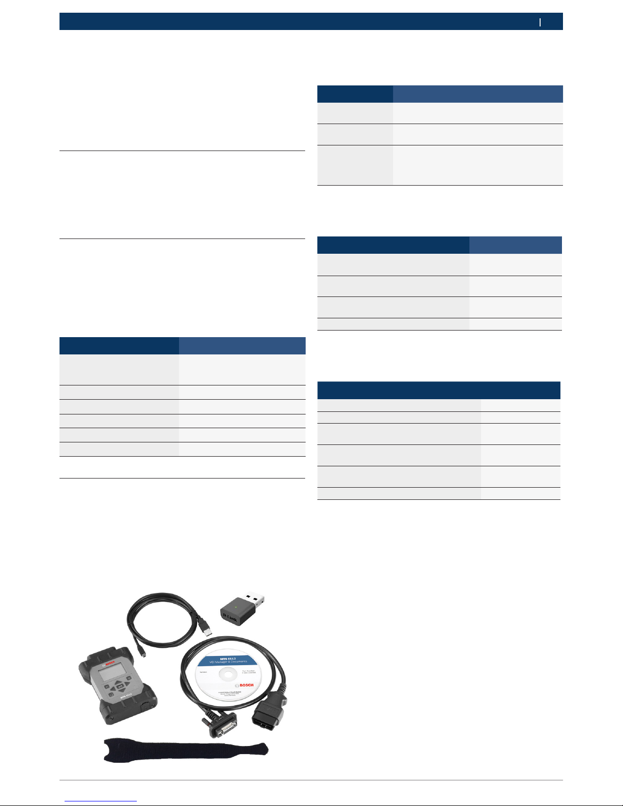
4.4 MTS 6513 Kit Contents
The MTS 6513 Base Kit includes cables and hardware
needed to transfer data and reprogram ECUs on vehicles
through the DLC connector.
The image below shows a MTS 6513 VCI kit with wireless
infrastructure mode (P/N 1699200116).
16992000121
2014-11-07
|
Robert Bosch GmbH
6 | MTS 6513 VCI | Product Description
enen
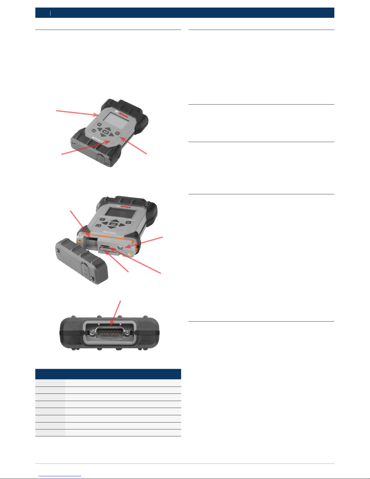
4.5 MTS 6513 Connectors and Controls
A number of standard connectors and controls are
available on the MTS 6513 to facilitate operation and
communication with vehicles and workshop networks.
These connectors and controls are shown in the following illustrations.
Item Description
1 LCD Display
2 Keypad
3 Power LED
4 USB Connector for (optional) Wi-Fi Interface
5 Reset Tab
6 Micro SD Card
7 USB mini "B" Connector
8 15P DLC Cable connector
4.6 Universal Serial Bus (USB)
The MTS 6513 has a fixed USB configuration which
cannot be changed. This ensures that the MTS 6513
can always be connected to a single PC running the VCI
Manager software so you can configure LAN or WLAN
settings required by your local network. In addition, it
is important to note that a USB connection is required
to configure and update the firmware on the MTS 6513
VCI.
4.7 Wireless Local Area Network (WLAN)
The 802.11 b/g/n WLAN connection on the MTS 6513
is set up and configured while the device is connected
over USB to a PC running the VCI Manager software.
4.8 VCI Manager Software
The VCI Manager software is a host computer application which runs on the Microsoft Windows operating
system to configure and update VCIs. The VCI Manager
software allows the configuration of VCI-to-host PC
communications and facilitates VCI firmware updates.
4.9 J2534 Pass-Thru Support
The MTS 6513 works with an OEM supplied J2534 PC
computer applications (PC program) for ECU Reflashing
and diagnostic applications.
The MTS 6513 supports pass-thru programming of
the flash calibration files that are stored in a vehicle
onboard controller (e.g., PCM, ABS, VTD). Refer to
specific operating instructions provided by the OEM
supplied J2534 PC application.
The MTS 6513 design is based on the SAE J2534
Pass-Thru and ISO 22900 Modular Vehicle Interface
standards, where the MTS 6513 VCI may be compatible with other software applications that use these API
standards.
4.10 Additional MTS 6513 VCI Features
4.10.1 Data Link Connector and Cable
Communication between the MTS 6513 and the
vehicle's electronic systems is through the 15-pin to 16pin Data Link Connector (DLC) cable that is connected
to the top center of the MTS 6513.
4.10.2 Power Source
The MTS 6513 is intended to be powered from the vehicle battery via the DLC Cable. The VCI may also be
powered using the USB cable connected to your PC.
Typically you use USB power when you are first configuring the VCI, updating software, and during testing
of the VCI. Important Note - The VCI must be powered
2
4
5 6
7
1
3
8
 Loading...