

Bosch MSI 60 User Manual
Modular Sensor Interface MSI 60
Manual
1 25/01/2019

Content
ii/120 Modular Sensor Interface MSI 60 Bosch Motorsport
Content
1 Getting started ................................................................................................................................................................ 5
2 Onboard Network Concept............................................................................................................................................ 6
3 Installation....................................................................................................................................................................... 7
4 Technical Data................................................................................................................................................................. 8
5 Inputs and Outputs......................................................................................................................................................... 10
5.1 Input Channels............................................................................................................................................................................................... 10
5.1.1 Basic Analog Inputs ................................................................................................................................................................... 10
5.1.2 Differential Analog Inputs ....................................................................................................................................................... 10
5.1.3 LVDT Inputs................................................................................................................................................................................... 12
5.1.4 Digital Inputs ................................................................................................................................................................................ 12
5.2 Output Channels........................................................................................................................................................................................... 13
5.2.1 PWM Outputs .............................................................................................................................................................................. 13
5.2.2 Sensor Power Supply................................................................................................................................................................. 13
5.3 Communication Channels ......................................................................................................................................................................... 13
5.3.1 CAN Bus.......................................................................................................................................................................................... 13
5.3.2 Ethernet Channels ...................................................................................................................................................................... 13
5.3.3 RS232 Port..................................................................................................................................................................................... 13
5.3.4 Vehicle Diagnosis Connector ................................................................................................................................................. 13
5.4 Pin Layout Connectors................................................................................................................................................................................ 15
5.4.1 Pin Layout Life Connector AS-2-12-35PN (Red)............................................................................................................. 15
5.4.2 Pin Layout Sensor Connector ASDD-2-14-64PA (Yellow)........................................................................................... 15
5.4.3 Pin Layout Sensor Connector ASDD-2-14-64PN (Red)................................................................................................ 18
6 Mechanical Drawing ....................................................................................................................................................... 21
7 Starting up....................................................................................................................................................................... 22
7.1 Before Starting............................................................................................................................................................................................... 22
7.1.1 Starting the MSI 60 .................................................................................................................................................................... 22
7.1.2 About RaceCon............................................................................................................................................................................ 22
7.1.3 Connecting the MSI 60 to RaceCon .................................................................................................................................... 22
7.2 Assign the Mounting Location ................................................................................................................................................................ 26
7.3 Feature Activation......................................................................................................................................................................................... 29
8 Math and Condition Channels....................................................................................................................................... 32
8.1 Math Channels............................................................................................................................................................................................... 32
8.1.1 Creating a new Math Channel............................................................................................................................................... 32
8.1.2 Creating a new Conditional Function ................................................................................................................................. 33
8.2 Condition Channels...................................................................................................................................................................................... 37
8.2.1 Creating a new Condition Channel...................................................................................................................................... 37
8.2.2 Creating a new Condition Combination............................................................................................................................ 39
9 CAN Bus ........................................................................................................................................................................... 41
9.1 CAN Bus Trivia .............................................................................................................................................................................................. 41
9.2 CAN Input ........................................................................................................................................................................................................ 42
9.2.1 Input Configuration ................................................................................................................................................................... 42
9.2.2 Create new CAN Channel ........................................................................................................................................................ 42
9.2.3 CAN Channel Configuration................................................................................................................................................... 43
9.2.4 Extracting Data from CAN Bus .............................................................................................................................................. 43
9.2.5 Conversion to Physical Values............................................................................................................................................... 45

Content
Bosch Motorsport Modular Sensor Interface MSI 60 iii/120
9.2.6 Special Features........................................................................................................................................................................... 45
9.2.7 Online View of CAN Channels in Vehicle .......................................................................................................................... 45
9.2.8 Import a CAN Database (DBC) File ...................................................................................................................................... 47
9.2.9 Export RaceCon CAN Configuration ................................................................................................................................... 47
9.2.10 Import RaceCon CAN Configuration................................................................................................................................... 48
9.3 CAN Output .................................................................................................................................................................................................... 49
9.3.1 Output Configuration ............................................................................................................................................................... 49
9.3.2 Create new CAN Output Message Channel..................................................................................................................... 50
9.3.3 Set up of Word Length, Byte Order and Quantization ................................................................................................ 50
9.3.4 Export RaceCon CAN Configuration ................................................................................................................................... 50
9.3.5 Import RaceCon CAN Configuration................................................................................................................................... 51
10 Analog and Frequency Inputs ....................................................................................................................................... 53
10.1 Features ............................................................................................................................................................................................................ 53
10.2 Measurement Channels.............................................................................................................................................................................. 53
10.3 Configuring Inputs ....................................................................................................................................................................................... 54
10.3.1 Configuring a predefined Bosch Sensor with the ‘Bosch Sensor Wizard’ ............................................................ 54
10.3.2 Configuring a generic linear Sensor.................................................................................................................................... 57
10.3.3 Configuring a generic nonlinear Sensor............................................................................................................................ 59
10.3.4 Configuring a PT 100 or PT 1000 Sensor........................................................................................................................... 62
10.3.5 Configuring an LVDT Sensor.................................................................................................................................................. 68
10.3.6 Configuring a Multipoint Adjustment ................................................................................................................................ 70
10.3.7 Digital Filter Details.................................................................................................................................................................... 73
10.3.8 Configuring a Frequency Input ............................................................................................................................................. 74
10.4 Configuring computed Sources.............................................................................................................................................................. 76
10.5 Hysteresis......................................................................................................................................................................................................... 77
10.5.1 Special Functionality: Vehicle speed ................................................................................................................................... 79
10.5.2 Setting up calculated Speed................................................................................................................................................... 79
10.6 Configuring PWM Outputs ....................................................................................................................................................................... 80
11 Online Measurement ...................................................................................................................................................... 84
11.1 Achieving an online Connection............................................................................................................................................................. 84
11.1.1 Set up the PC for Access ......................................................................................................................................................... 84
11.1.2 Going online ................................................................................................................................................................................. 85
11.1.3 Configuration Download ......................................................................................................................................................... 85
11.2 Setting up an online Measurement....................................................................................................................................................... 86
11.2.1 Automatic Creation of Measurement Sheets .................................................................................................................. 90
11.2.2 Using the Measurement Sheets............................................................................................................................................ 91
11.3 Online Calibration of Measurement Channels .................................................................................................................................. 91
11.3.1 Enable online offset Calibration for Measurement Channel...................................................................................... 92
11.3.2 Performing the online offset Calibration........................................................................................................................... 92
11.4 Group Adjustment........................................................................................................................................................................................ 93
11.5 Online Calibration of Multipoint Adjustment Channels ................................................................................................................ 95
12 Error Memory .................................................................................................................................................................. 98
12.1 Error memory representation in RaceCon .......................................................................................................................................... 98
12.1.1 Accessing the memory ............................................................................................................................................................. 98
12.1.2 Clearing the error memory ..................................................................................................................................................... 99
12.2 Information on errors available from the error memory............................................................................................................... 100
12.2.1 Error Memory Properties ......................................................................................................................................................... 100
12.2.2 Error Properties ........................................................................................................................................................................... 102
12.3 Analog Input Diagnosis.............................................................................................................................................................................. 104
12.3.1 Monitoring limits / Shortcut Detection / Cable Breakage.......................................................................................... 104

Content
iv/120 Modular Sensor Interface MSI 60 Bosch Motorsport
12.3.2 Open Line Detection ................................................................................................................................................................. 105
13 Firmware .......................................................................................................................................................................... 106
13.1 Firmware and Configuration..................................................................................................................................................................... 106
13.2 Firmware Update........................................................................................................................................................................................... 106
14 Clone the Unit ................................................................................................................................................................. 109
15 GPS Sensor....................................................................................................................................................................... 111
15.1 GPS (Global Positioning System)............................................................................................................................................................ 111
15.2 Protocol ............................................................................................................................................................................................................ 111
15.3 Sensor Recommendation .......................................................................................................................................................................... 111
15.4 Measurement Labels ................................................................................................................................................................................... 112
15.5 GPS Troubleshooting .................................................................................................................................................................................. 113
16 RaceCon Shortcuts.......................................................................................................................................................... 114
17 Disposal............................................................................................................................................................................ 115
18 Error Memory .................................................................................................................................................................. 116
18.1 General Note .................................................................................................................................................................................................. 116
18.2 Error Memory Representation in RaceCon ......................................................................................................................................... 116
18.2.1 Accessing the Memory ............................................................................................................................................................. 116
18.2.2 Cleaning the Error Memory .................................................................................................................................................... 116
18.3 Information on Errors available from the Error Memory............................................................................................................... 116
18.3.1 Error Memory Properties ......................................................................................................................................................... 116
18.3.2 Error Properties ........................................................................................................................................................................... 116
18.4 Configuration ................................................................................................................................................................................................. 116
18.4.1 Monitoring limits / Shortcut Detection / Cable Breakage.......................................................................................... 116
18.4.2 Open Line Detection ................................................................................................................................................................. 116

Getting started | 1
Bosch Motorsport Modular Sensor Interface MSI 60 5/120
1 Getting started
Use the MSI 60 only as intended in this manual. Any maintenance or repair must be performed by authorized and qualified personnel approved by Bosch Motorsport.
Operation of the MSI 60 is only certified with the combinations and accessories that are
specified in this manual. The use of variant combinations, accessories and other devices
outside the scope of this manual are only permitted when they have been determined to
be compliant from a performance and safety standpoint by a representative from Bosch
Motorsport. Read the manual carefully and follow the application hints step by step. Don’t
hesitate to contact us, contact data can be found on the back page of this document.
Disclaimer
Due to continuous enhancements we reserve the rights to change any illustrations, photos
and technical data within this manual.
2 | Onboard Network Concept
6/120 Modular Sensor Interface MSI 60 Bosch Motorsport
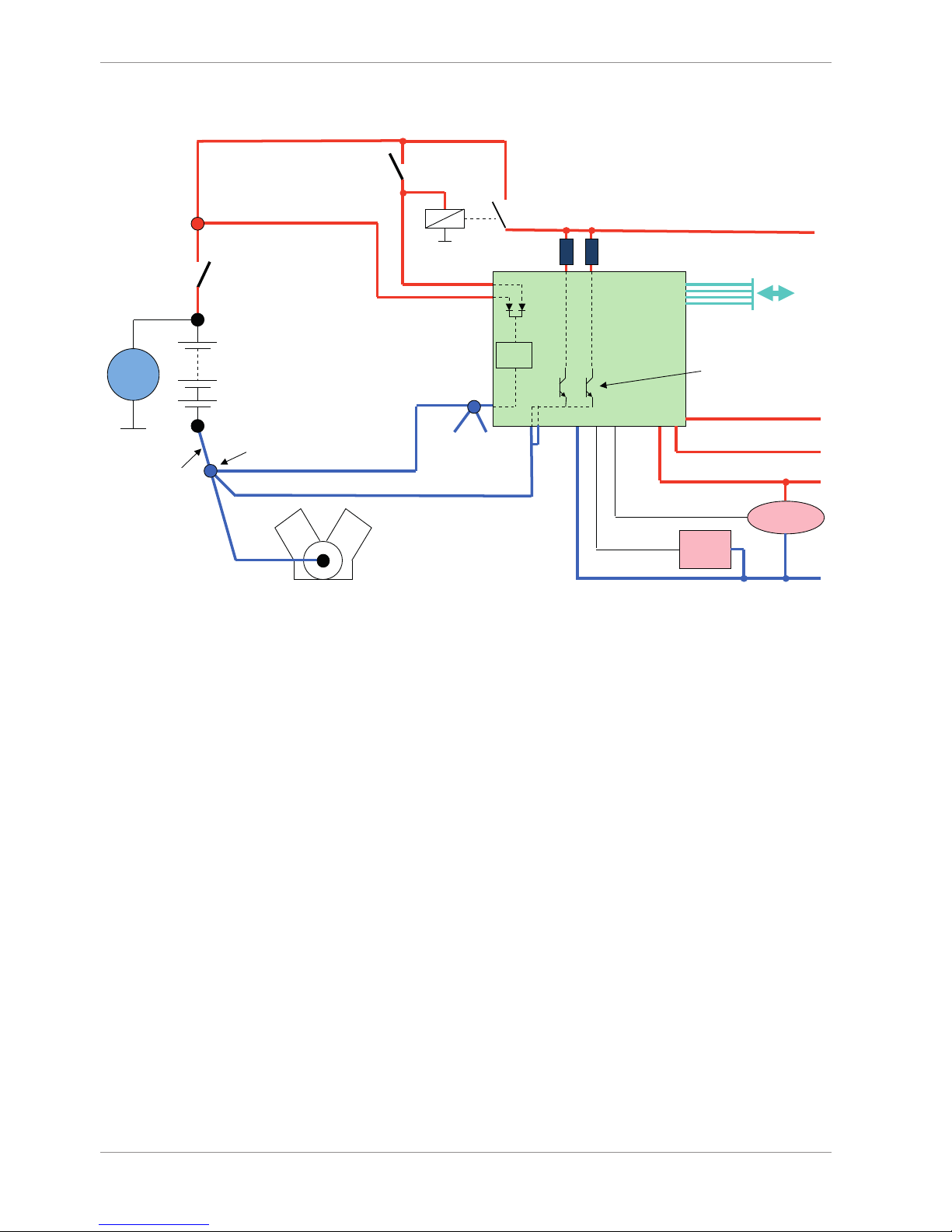
2 Onboard Network Concept
G
Engine_GND
GND_Starpoint
Chassis
KL31
LS_GND_1
LS_GND_2
Main
Switch
UBAT
Star connection
(term30)
positive terminal
Electric Loads
IGN-
Switch
KL15
SENSPWR5
SENSGND
active
Sensor
ANA_IN(xx)
NTC
Sensor
ANA_IN(xy)
switched pos. terminal
Star connection
dig. sensors
(e.g. wheelspeed)
µC
As short as
possible
SENSPWR10
UBATT_FUSE
KL30
LS_SWITCH1…4
Bosch Motorsport
diagnosis connector
PC
Device

Installation | 3
Bosch Motorsport Modular Sensor Interface MSI 60 7/120
3 Installation
Power Supply
Please ensure that you have a good ground installation. That means:
– A ground that has a solid, low resistance connection to the negative battery terminal.
– Connection should be free from dirt, grease, paint, anodizing etc.
– Use large diameter wire.
– More metal-to-metal contact is better!
The following notations for power signals are used:
– KL 15 is a switched battery rail controlled by the IGN-switch.
– KL 30 is an unswitched battery positive rail (same as battery positive terminal).
– KL 31 is an unswitched ground rail (same as battery negative terminal).
NOTICE
Be careful to observe current limits of wires and connector pins!
4 | Technical Data
8/120 Modular Sensor Interface MSI 60 Bosch Motorsport
4 Technical Data
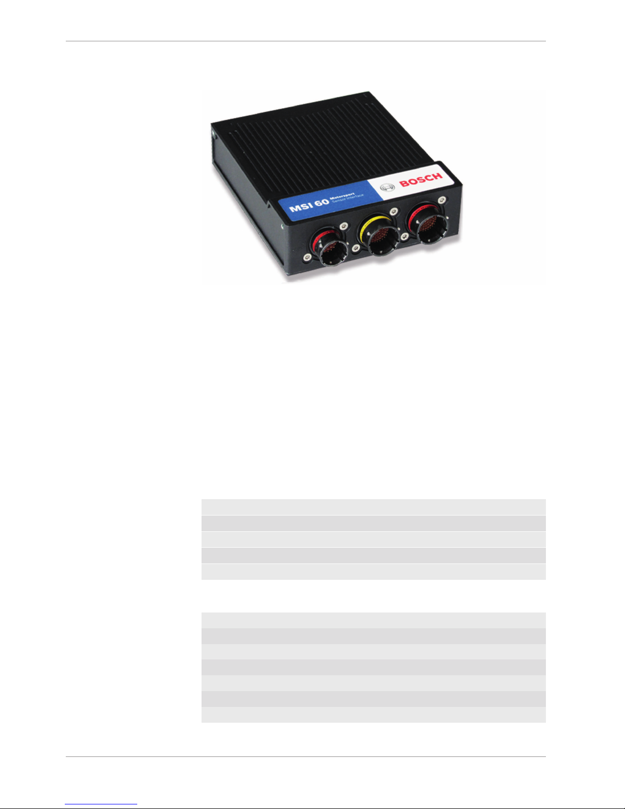
The MSI 60 is a high quality signal conditioning and data acquisition unit for analogue, digital, frequency and linear variable differential (LVDT) sensors.
MSI 60 offers a large number of freely configurable inputs (32 x differential analogue, 8 x
single ended analogue, 8 x LVDT, 2 x frequency, 1 x RS 232 for GPS). Possible applications
of the differential inputs include e.g. 31 TC-J type or TC-K type temperature sensors arranged in a sensor array (one diff. input used for compensation), PT100, PT1000 (specific
pull up values available), NTC, strain gauges etc. Each differential input features 200 times
oversampling.
The cut-off frequency of the digital filters in all inputs is automatically adjusted to match
the acquisition rate. MSI 60 also corrects the latency of the digital filters during recording,
yielding zero filter delay in the recorded data. Quantization of each MSI measurement
channel is individually configurable. Data can be sent via Ethernet interface to any Bosch
Motorsport logging device.
Application
AD converters with digital low pass filter
Configurable math channels
User configurable CAN in/out messages
Up to 1,000Hz acquisition rate for all channels
3-port network switch
Mechanical Data
Size 153 x 119 x 38 mm
Weight 645 g
Aluminum housing
High density type motorsport connectors
Vibration damped printed circuit boards
Operating temperature -20 to 85°C
Max. vibration 15 g sinus at 1,200 Hz for t < 5 h

Technical Data | 4
Bosch Motorsport Modular Sensor Interface MSI 60 9/120
Electrical Data
Supply voltage 7 to 18V
Max. power consumption (w/o sensor power supply) 15W
Inputs
Analog inputs, 0 to 5V, 12bit
Switchable pull-up value, 3.01kOhm
8
Differential analog inputs -5 to +5V, 18bit, 3 pull-ups 32
LVDT inputs 8
Rotational inputs 4
Outputs
PWM outputs (low side switch 1A each) 4
Sensor supply 5V (400mA each), precision: 0.1 % (up
to 300), 0.2% (max. 300mA)
2
Sensor supply 5V/10V (200mA each) 2
Sensor supply 12V (800mA, non regulated) 1
Environment
Software Upgrade 1
CCP-Master (ASAP 2 file from ECU manufacturer required)
F 02U V01 012-01
Connectors and Wires
Motorsports connectors double density 2 x 64 pin and 1 x 34 pin
Mating connector I
AS-2-12-35PN (Red)
F02U 000 443-01
Mating connector II
ASDD-2-14-64PA (Yellow)
F02U 003 098-01
Mating connector III
ASDD-2-14-64PN (Red)
F02U 000 854-01
Communication
Configuration via RaceCon over Ethernet or MSA-Box II
2 CAN interfaces
3 Ethernet 100BaseT
RS232 for GPS
The required software for this device is available on www.bosch-motorsport.com.
5 | Inputs and Outputs
10/120 Modular Sensor Interface MSI 60 Bosch Motorsport
5 Inputs and Outputs
The following chapter introduces the Input and Output Channels.
5.1 Input Channels
The MSI 60 provides diverse analog inputs which allows the direct connection of a multiplicity number of sensors.
5.1.1 Basic Analog Inputs
The MSI 60 basic analog inputs accept an input signal of 0 to 5 V. A 3.01 kOhm pull-up
resistor can be activated by software.
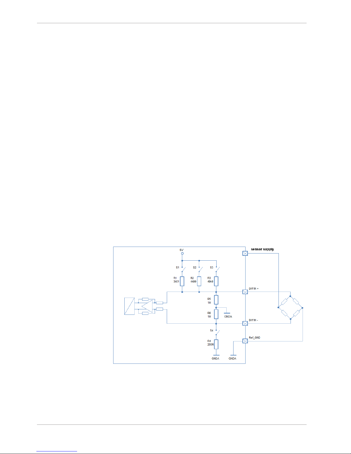
5.1.2 Differential Analog Inputs
The MSI 60 differential analog inputs offers a wide configurability. The inputs can be
switched between single ended or differential mode. In single ended mode input signals
of 0 to 5 V are accepted. In differential mode input signals are accepted in the range of -5
V to +5 V.
Three pull-up resistors can be activated by software. A 3.01 kOhm resistor can be used for
evaluation both ntc sensors and switches or push-buttons.
The resistors of 4.99 kOhm and 49.9 kOhm provide the direct connection of PT100 and
PT1000 sensors.
A selectable amplification of small input signals allows the direct connection of resistive
strain gauges.
For further wiring details please refer to the given figures.
Illustration1: Differential sensor
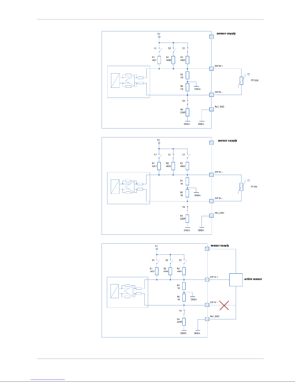
Inputs and Outputs | 5
Bosch Motorsport Modular Sensor Interface MSI 60 11/120
Illustration2: Differential_PT1000 sensor
Illustration3: Differential_PT100 sensor
Illustration4: Single ended sensor
5 | Inputs and Outputs
12/120 Modular Sensor Interface MSI 60 Bosch Motorsport
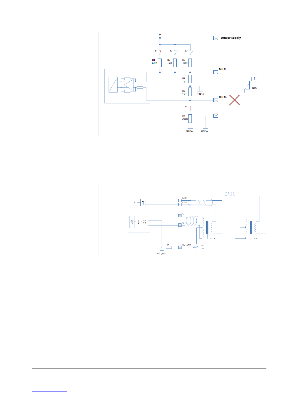
Illustration5: NTC sensor
5.1.3 LVDT Inputs
The MSI 60 LVDT inputs allows the connection of various LVDT sensors. Switchable exciting voltage and frequency are used for the correct adaption of the applied sensor. For further wiring details please refer to the following figure:
Illustration6: LVDT
For further details see on chapter Configuring an LVDT Sensor [}68].
See also
2
Online Calibration of Measurement Channels [}91]
5.1.4 Digital Inputs
The digital inputs of the MSI 60 can be switched for the direct connection of Hall-effect,
inductive and DF11 sensors.
– For Hall-effect sensors an input signal from 0 V to 5 V is accepted.
– For inductive sensors a zero-crossing signal is necessary.
Connect the sensor between I_F_REVx and digital ground G_R_DIGx.

Inputs and Outputs | 5
Bosch Motorsport Modular Sensor Interface MSI 60 13/120
5.2 Output Channels
This chapter describes the PWM Output and Sensor Power Supply of the MSI 60.
5.2.1 PWM Outputs
The MSI 60 has 4 low side switch outputs controlled by pulse width modulation (PWM).
Each switch is rated 1 A maximum current. Maximum PWM switch frequency is 1 kHz with
a 0 % … 100 % duty cycle. Each output is short circuit protected to GND and battery
voltage. It is mandatory to connect the LS_PWM pins to vehicle GND as indicated in the
circuit diagram when using the PWM outputs.
5.2.2 Sensor Power Supply
The MSI 60 has three types of sensor power supply:
– One 12 V unregulated battery voltage
– Two fixed outputs with 5 V regulated
– Two switchable 5 V/10 V outputs with regulated voltage
5.3 Communication Channels
This chapter describes the Communication Channels of the MSI 60.
5.3.1 CAN Bus
The MSI 60 has 2 CAN buses configurable as input and output. Different baud rates are
selectable. Please note that the MSI 60 does not contain any CAN termination resistors.
Thus the CAN termination resistors need to be integrated into the wiring loom.
5.3.2 Ethernet Channels
The MSI 60 has three 100 Mbit full duplex Ethernet communication ports. The ports are
internally connected with an Ethernet switch. The Ethernet ports have 'cable auto crossover' functionality.
5.3.3 RS232 Port
The MSI 60 has one RS232 serial port. The baudrate is programmable which can be used
for reception of data from a serial GPS sensor, see on GPS Sensor [}111].
5.3.4 Vehicle Diagnosis Connector
The Bosch Motorsport vehicle diagnosis connector is used as a standard interface to connect the vehicle to a PC e.g. via a MSA-Box II. Loom Connector: AS0-12-35SN.
PIN Name Description Used for MSI 60
1 Terminal 30 Permanent positive +
2 Terminal 15 Switched positive +
3 Terminal 31 GND +
4 CAN High Diagnostic CAN bus

5 | Inputs and Outputs
14/120 Modular Sensor Interface MSI 60 Bosch Motorsport
PIN Name Description Used for MSI 60
16 CAN Low Diagnostic CAN bus
10 K-Line ECU diagnosis
8 Ethernet RxD + Ethernet interface +
9 Ethernet RxD - Ethernet interface +
11 Ethernet TxD + Ethernet interface +
12 Ethernet TxD - Ethernet interface +
22 Screen Cable screen +

Inputs and Outputs | 5
Bosch Motorsport Modular Sensor Interface MSI 60 15/120
5.4 Pin Layout Connectors
5.4.1 Pin Layout Life Connector AS-2-12-35PN (Red)
PIN Name Description Direction Remark
1 V_V_BAT+_A UBATT ECU Input ECU SUPPLY
2 V_V_BAT+_A UBATT ECU Input ECU SUPPLY
3 I_S_T15 KL15 input signal ignition Input
4 G_G_BAT GND not sc safe to
UBATT
5 G_G_BAT GND not sc safe to
UBATT
6 B_D_ETH0_RX- Ethernet Channel1 Rx minus
7 B_D_ETH0_TX- Ethernet Channel1 Tx minus
8 B_D_ETH1_TX- Ethernet Channel2 Tx minus
9 B_D_ETH1_RX- Ethernet Channel2 Rx minus
10 B_D_ETH1_RX+ Ethernet Channel2 Rx plus
11 B_D_ETH2_RX- Ethernet Channel3 Rx minus
12 B_D_ETH2_TX- Ethernet Channel3 Tx minus
13 B_D_ETH2_TX+ Ethernet Channel3 Tx plus
14 B_D_CAN_L_A CAN A Low CAN A Low
15 B_D_CAN_H_A CAN A High CAN A High
16 O_V_UBAT Output switched UBATT Output
17 B_D_ETH0_RX+ Ethernet Channel1 Rx plus
18 B_D_ETH0_TX+ Ethernet Channel1 Tx plus
19 B_D_ETH1_TX+ Ethernet Channel2 Tx plus
20 B_D_ETH2_RX+ Ethernet Channel3 Rx plus
21 G_R_SCREEN Screen Screen
22 I_F_TIMESYNC SYNCH_CLKIN
5.4.2 Pin Layout Sensor Connector ASDD-2-14-64PA
(Yellow)
PIN Name Description Direction Remark
1 G_R_LVDT LVDT REF GND LVDT GND &
SCREEN
2 LS_SWITCH_2 Output LowSide 2 Output 1.1 A
3 LS_SWITCH_1 Output LowSide 1 Output 1.1 A
4 EXC1_4 LVDT exciting voltage + Output LVDT 4
5 VA_4 LVDT input A Input LVDT 4
6 EXC1_3 LVDT exciting voltage + Output LVDT 3
7 EXC2_2 LVDT exciting voltage + Output LVDT 2
8 VB_2 LVDT B Input LVDT 2

5 | Inputs and Outputs
16/120 Modular Sensor Interface MSI 60 Bosch Motorsport
PIN Name Description Direction Remark
9 VA_1 LVDT A Input LVDT 1
10 SE_ANA_1 Analog input 0 to 5 V, switchable
pull-up
Input RPU: 3k01
11 SE_ANA_3 Analog input 0 to 5 V, switchable
pull-up
Input RPU: 3k01
12 UNI_ANA_16_P Input RPU: 3k01 or
4k99 or 49k9
13 UNI_ANA_15_N Input
14 UNI_ANA_13_N Input
15 UNI_ANA_12_P Input RPU: 3k01 or
4k99 or 49k9
16 UNI_ANA_10_N Input
17 UNI_ANA_08_P Input RPU: 3k01 or
4k99 or 49k9
18 UNI_ANA_07_N Input
19 UNI_ANA_04_P Input RPU: 3k01 or
4k99 or 49k9
20 UNI_ANA_06_N Input
21 UNI_ANA_05_N Input
22 UNI_ANA_02_P Input RPU: 3k01 or
4k99 or 49k9
23 UNI_ANA_01_N Input
24 Reserved. Do not connect.
25 B_D_CAN B Low CAN B Low CAN B LOW
26 G_R_DIG1 Ground Reference DIG1 REV IN
27 EXC2_4 LVDT exciting voltage - LVDT 4
28 VB_4 LVDT input B Input LVDT 4
29 EXC2_3 LVDT exciting voltage - Input LVDT 3
30 EXC1_2 LVDT exciting voltage + Input LVDT 2
31 VA_2 LVDT input A Input LVDT 2
32 VB_1 LVDT input B Input LVDT 1
33 SE_ANA_2 Analog input 0 to 5 V, switchable
pull-up
Input RPU: 3k01
34 UNI_ANA_16_N Input
35 UNI_ANA_15_P Input RPU: 3k01 or
4k99 or 49k9
36 UNI_ANA_13_P Input RPU: 3k01 or
4k99 or 49k9
37 UNI_ANA_11_N Input
38 UNI_ANA_08_N Input
39 UNI_ANA_07_P Input RPU: 3k01 or
4k99 or 49k9

Inputs and Outputs | 5
Bosch Motorsport Modular Sensor Interface MSI 60 17/120
PIN Name Description Direction Remark
40 UNI_ANA_06_P Input RPU: 3k01 or
4k99 or 49k9
41 UNI_ANA_03_P Input RPU: 3k01 or
4k99 or 49k9
42 UNI_ANA_02_N Input
43 UNI_ANA_01_P Input RPU: 3k01 or
4k99 or 49k9
44 B_D_CAN B High CAN B High CAN B High
45 VA_3 LVDT input A Input LVDT 3
46 VB_3 LVDT input B Input LVDT 3
47 EXC1_1 LVDT exciting voltage + Input LVDT 1
48 EXC2_1 LVDT exciting voltage - Input LVDT 1
49 G_R_AGND1 Reference GND1 for analog inputs Input not sc save to
UBATT
50 SE_ANA_4 Analog input 0 to 5 V, switchable
pull-up
Input RPU: 3k01
51 UNI_ANA_14_P RPU: 3k01 or
4k99 or 49k9
52 UNI_ANA_12_N
53 UNI_ANA_10_P RPU: 3k01 or
4k99 or 49k9
54 UNI_ANA_04_N
55 UNI_ANA_03_N
56 UNI_ANA_05_P RPU: 3k01 or
4k99 or 49k9
57 I_F_REV1 Revolution/Frequeny input I-encoder
wheel / Hall /
DF11
58 SENSPWR_5V Sensor supply 5 V, 400 mA max.
59 SENSPWR_5V_10V Sensor supply 5 V, 10 V, 200 mA
max.
not sc safe to
UBATT
60 G_R_AGND2 Reference GND2 for analog inputs Input not sc safe to
UBATT
61 UNI_ANA_14_N Input
62 UNI_ANA_11_P Input RPU: 3k01 or
4k99 or 49k9
63 UNI_ANA_09_P Input RPU: 3k01 or
4k99 or 49k9
64 UNI_ANA_09_N Input

5 | Inputs and Outputs
18/120 Modular Sensor Interface MSI 60 Bosch Motorsport
5.4.3 Pin Layout Sensor Connector ASDD-2-14-64PN
(Red)
PIN Name Description Direction Remark
1 DGND2 LVDT REF GND LVDT GND &
SCREEN
2 LS_SWITCH_4 Output LowSide 4 1.1 A
3 LS_SWITCH_3 Output LowSide 3 1.1 A
4 EXC1_8 LVDT exciting voltage + LVDT 8
5 VA_8 LVDT input A LVDT 8
6 EXC1_7 LVDT exciting voltage + LVDT 7
7 EXC2_6 LVDT exciting voltage - LVDT 6
8 VB_6 LVDT input B LVDT 6
9 VA_5 LVDT input A LVDT 5
10 SE_ANA_5 Analog input 0 to 5 V, switchable
pull-up
RPU: 3k01
11 SE_ANA_7 Analog input 0 to 5 V, switchable
pull-up
RPU: 3k01
12 UNI_ANA_32_P RPU: 3k01 or
4k99 or 49k9
13 UNI_ANA_31_N
14 UNI_ANA_29_N
15 UNI_ANA_28_P RPU: 3k01 or
4k99 or 49k9
16 UNI_ANA_26_N
17 UNI_ANA_24_P RPU: 3k01 or
4k99 or 49k9
18 UNI_ANA_23_N
19 UNI_ANA_20_P RPU: 3k01 or
4k99 or 49k9
20 UNI_ANA_22_N
21 UNI_ANA_21_N
22 UNI_ANA_18_P RPU: 3k01 or
4k99 or 49k9
23 UNI_ANA_17_N
24 B_D_PSI5_2 Reserved. Do not connect.
25 RS232A TX RS232 transmit
26 G_R_DIG2 Ground reference DIG2 REV IN
27 EXC2_8 LVDT exciting voltage - LVDT 8
28 VB_8 LVDT input B LVDT 8
29 EXC2_7 LVDT exciting voltage - LVDT 7
30 EXC1_6 LVDT exciting voltage + LVDT 6
31 VA_6 LVDT input A LVDT 6
32 VB_5 LVDT input B

Inputs and Outputs | 5
Bosch Motorsport Modular Sensor Interface MSI 60 19/120
PIN Name Description Direction Remark
33 SE_ANA_6 Analog input 0 to 5 V, switchable
pull-up
RPU: 3k01
34 UNI_ANA_32_N
35 UNI_ANA_31_P RPU: 3k01 or
4k99 or 49k9
36 UNI_ANA_29_P RPU: 3k01 or
4k99 or 49k9
37 UNI_ANA_27_N
38 UNI_ANA_24_N
39 UNI_ANA_23_P RPU: 3k01 or
4k99 or 49k9
40 UNI_ANA_22_P RPU: 3k01 or
4k99 or 49k9
41 UNI_ANA_19_P RPU: 3k01 or
4k99 or 49k9
42 UNI_ANA_18_N
43 UNI_ANA_17_P RPU: 3k01 or
4k99 or 49k9
44 RS232A RX RS232 receive
45 VA_7 LVDT input A LVDT 7
46 VB_7 LVDT input B LVDT 7
47 EXC1_5 LVDT exciting voltage + LVDT 5
48 EXC2_5 LVDT exciting voltage - LVDT 5
49 G_R_AGND3 Reference GND3 for analog inputs not sc safe to
UBATT
50 SE_ANA_8 Analog input 0 to 5 V, switchable
pull-up
RPU: 3k01
51 UNI_ANA_30_P RPU: 3k01 or
4k99 or 49k9
52 UNI_ANA_28_N
53 UNI_ANA_26_P RPU: 3k01 or
4k99 or 49k9
54 UNI_ANA_20_N
55 UNI_ANA_19_N
56 UNI_ANA_21_P RPU: 3k01 or
4k99 or 49k9
57 I_F_REV2 Revolution/frequency input. I-encoder
wheel / Hall /
DF11
58 SENSPWR_5V Sensor supply 5 V, 400 mA max.
59 SENSPWR_5V_10V Sensor supply 5 V, 10 V, 200 mA
max.
60 G_R_AGND4 Reference GND4 for analog inputs not sc safe to
UBATT

5 | Inputs and Outputs
20/120 Modular Sensor Interface MSI 60 Bosch Motorsport
PIN Name Description Direction Remark
61 UNI_ANA_30_N
62 UNI_ANA_27_P RPU: 3k01 or
4k99 or 49k9
63 UNI_ANA_25_P RPU: 3k01 or
4k99 or 49k9
64 UNI_ANA_25_N
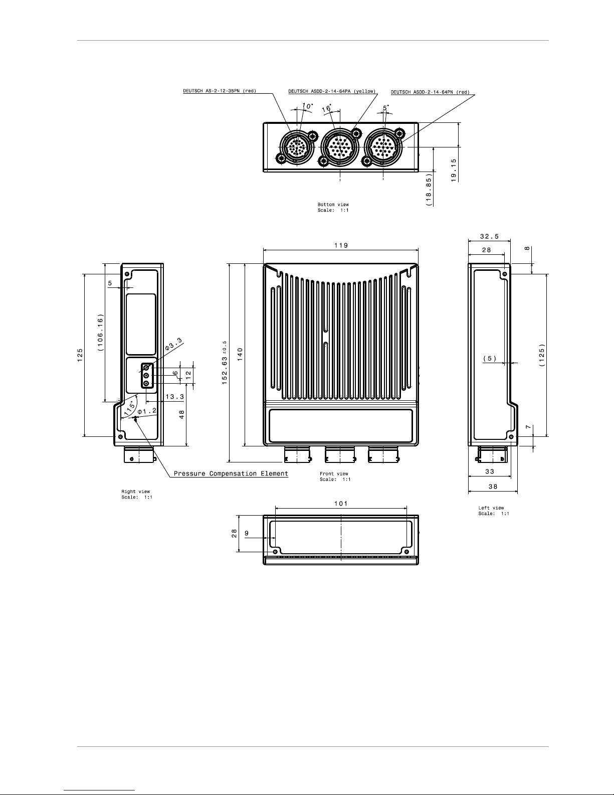
Mechanical Drawing | 6
Bosch Motorsport Modular Sensor Interface MSI 60 21/120
6 Mechanical Drawing

7 | Starting up
22/120 Modular Sensor Interface MSI 60 Bosch Motorsport
7 Starting up
The following chapter explains what you have to do before starting the MSI 60 and how
to connect it to RaceCon.
7.1 Before Starting
Install the software required for MSI 60 operation. It is developed for Windows 2000/XP/
Vista/7. Following software versions are used in this manual:
– MSI 60 setup, configuration and calibration: RaceCon V2.5 and following
– Measurement data analysis: WinDarab V7
Set up the 100 Mbit Ethernet connection to the MSI 60.
– All three Ethernet ports of MSI 60 are internally connected by a network switch.
– All Ethernet ports have ‘cable auto crossover’ functionality.
Minimum wiring loom of the Life connector (Red):
PIN Description
1+2+3 12 V Supply Voltage
4+5 GND Supply Voltage
18 Ethernet Tx+
7 Ethernet Tx-
17 Ethernet Rx+
6 Ethernet Rx-
21 Ethernet Screen
7.1.1 Starting the MSI 60
The MSI 60 powers up by turning on the ignition of the car.
The ‘Link LED’ at the PC’s network adapter will illuminate. If the LED is off, check the wiring
harness.
7.1.2 About RaceCon
RaceCon is an all integrated software tool for configuration and calibration of Bosch Motorsport hardware products. It is used to set up, configure and calibrate the MSI 60.
For better understanding, Bosch Motorsport offers a video tutorial that explains many
functions of RaceCon. The video tutorial is available in the ‘Software Download’ section on
www.bosch-motorsport.com.
7.1.3 Connecting the MSI 60 to RaceCon
The following screenshot shows an overview of the RaceCon main screen with its areas. All
(sub-) windows are resizable and dockable.
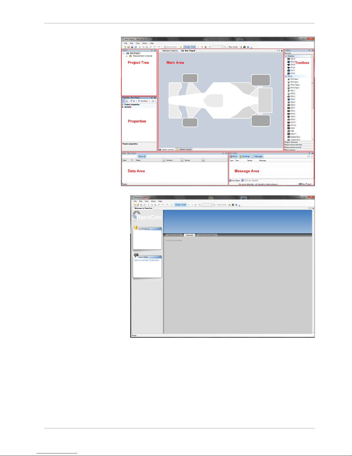
Starting up | 7
Bosch Motorsport Modular Sensor Interface MSI 60 23/120
1. Start the RaceCon software.
7 | Starting up
24/120 Modular Sensor Interface MSI 60 Bosch Motorsport
2. In the ‘File’ menu select ‘New’ to create a new project.
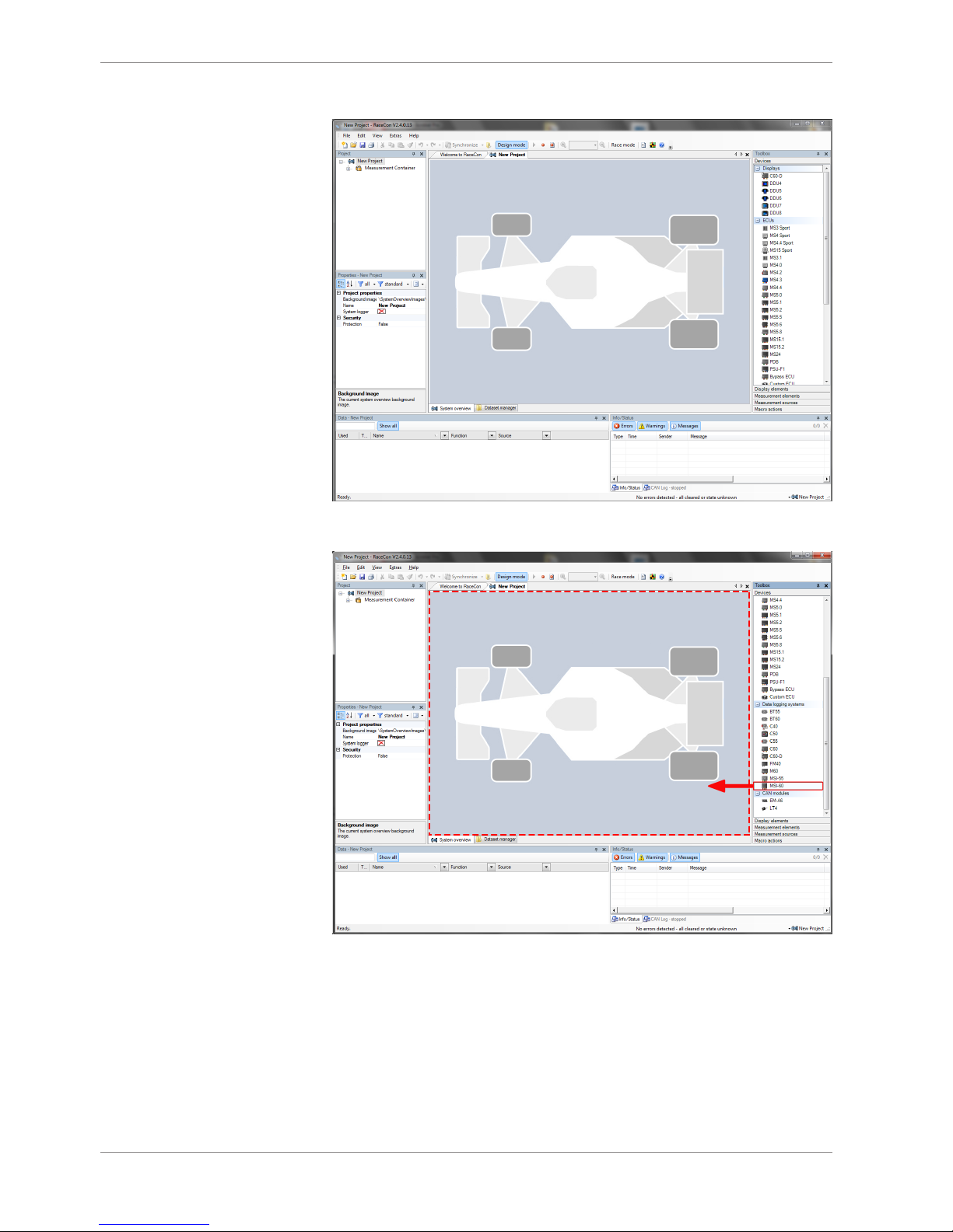
3. In the Toolbox select the MSI 60 and drag it into the Main Area. A pop-up window to
specify the MSI 60 program archive appears.
Starting up | 7
Bosch Motorsport Modular Sensor Interface MSI 60 25/120
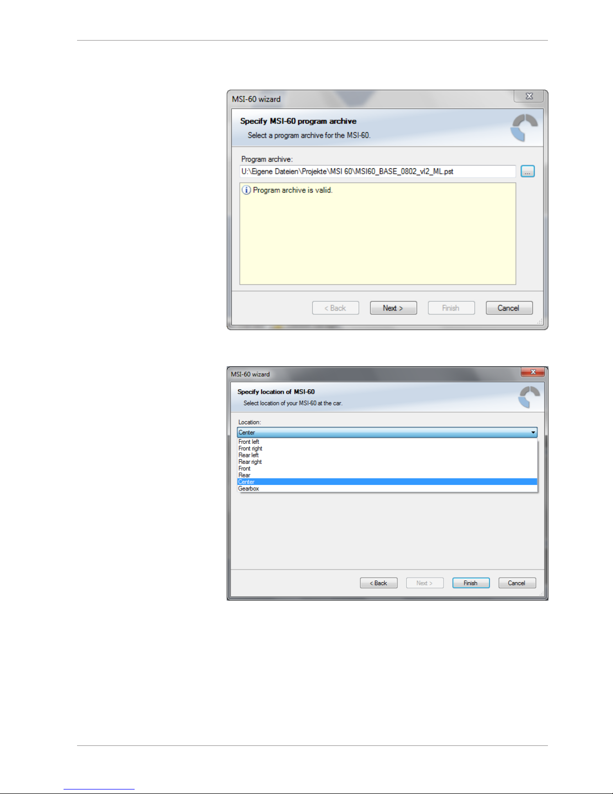
4. Select the program archive delivered with the MSI 60 (.PST file). An information shows
that the archive is valid or not.
5. Click ‘Next’.
6. Select location of MSI 60.
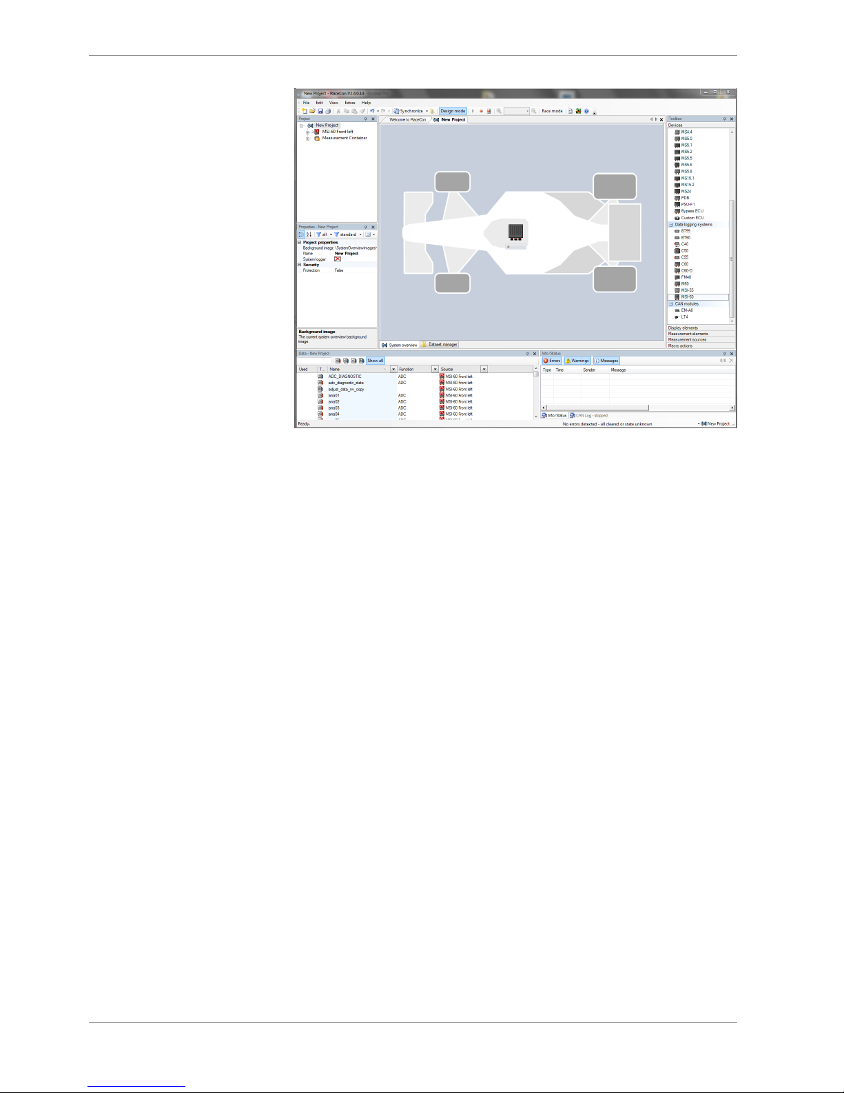
7. Click ‘Finish’. The MSI 60 is inserted into the project and RaceCon tries to connect to
the device. Repeat the bespoken procedure for every additional MSI 60 . If you are
starting with a new delivered MSI 60 you once-only need to assign the mountain location(s). Please refer to Assign the Mounting Location [}26].
7 | Starting up
26/120 Modular Sensor Interface MSI 60 Bosch Motorsport
RaceCon detects configuration differences between the MSI 60 and the RaceCon project and asks for permission for data download.
8. Click ‘OK’ to proceed.
The download starts and the MSI 60 carries out a reset. After the reset RaceCon reconnects to the MSI 60 . Local configuration on both the PC and MSI 60 match (indicated by
green background and dot). The MSI 60 is now connected to RaceCon.
7.2 Assign the Mounting Location
Because up to eight MSI 60 can be used in one network for I/O expansion, the mounting
location is used for determination between the different MSI 60.
At delivery no mounting location is set. This is signaled by an orange ‘RUN’ LED on the
device. Therefore one must first assign a mounting location to the MSI 60 before it can be
used in the project. The mounting location is permanently saved in the MSI 60. If necessary you can at any time reassign a different mounting location following the same procedure.
A mounting location must not be used several times in one network, this would disturb
the functionality of the respective MSI 60.

Starting up | 7
Bosch Motorsport Modular Sensor Interface MSI 60 27/120
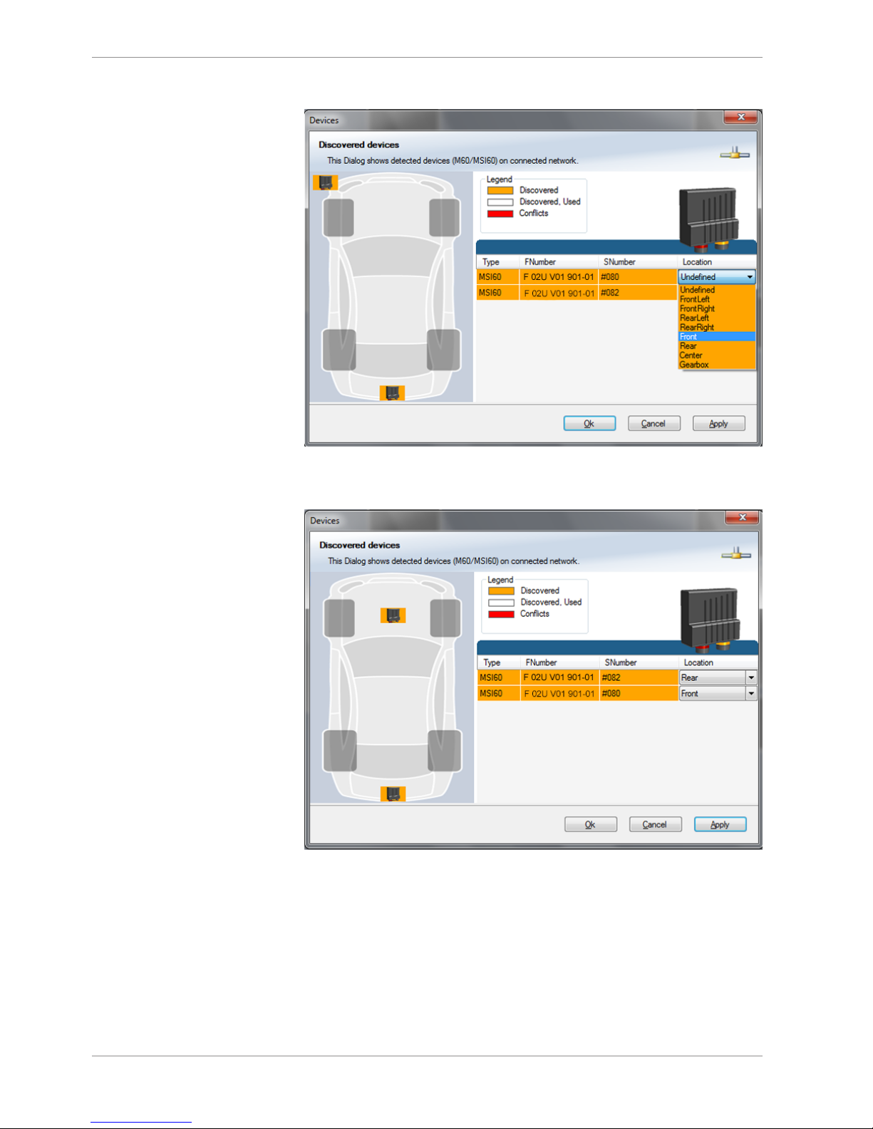
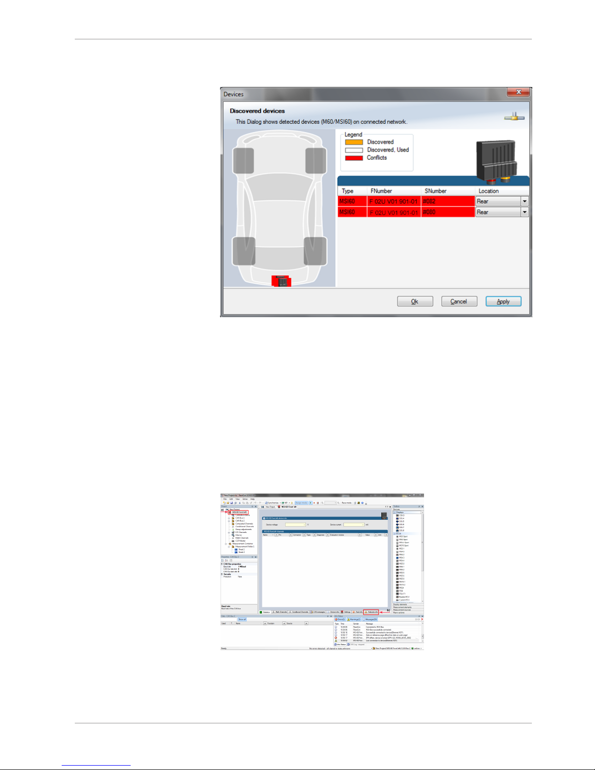
1. In the Project Tree, right click on the project name e.g. ‘New Project’ and then select
‘Show discovered devices…’.
All connected MSI 60 are listed.
2. Compare the listed device Type, FNumber and SNumber to the identification plate to
identify the device you want to make changes to:
7 | Starting up
28/120 Modular Sensor Interface MSI 60 Bosch Motorsport
3. Assign the desired mounting location (e.g. ‘Front’) and confirm by clicking ‘Apply’.
The mounting location is now stored in the device. The device will do a reset and the
‘RUN’ LED on the device will change to green. The list will show the new mounting
location assignment.
It is good practice to physically label the MSI 60 with its mounting location.
Now the device is ready to be used.
A different coloring of the MSI 60 is used to indicate that the device is already configured in the currently loaded RaceCon project or not (white/orange).
Starting up | 7
Bosch Motorsport Modular Sensor Interface MSI 60 29/120
A conflict of several connected MSI 60 using the same location is indicated by red coloring the involved devices:
7.3 Feature Activation
– If you have purchased an optional software feature package, it must be activated be-
fore it becomes operational.
– The feature activation status is stored permanently in the device and requires activat-
ing once only.
– As the activation key is device specific, a key delivered with one MSI 60 does not work
on any other MSI 60.
– If you have not purchased an option package, the next steps can be skipped.
1. To activate a feature, double-click on ‘MSI 60’ in the Project Tree and click on the
‘Features info’ tab in the Main Area.
a) Double-click on ‘ ’.
b) Click on ‘Features Info’. The ‘features info’ window appears.
MSI 60
MSI 60
7 | Starting up
30/120 Modular Sensor Interface MSI 60 Bosch Motorsport
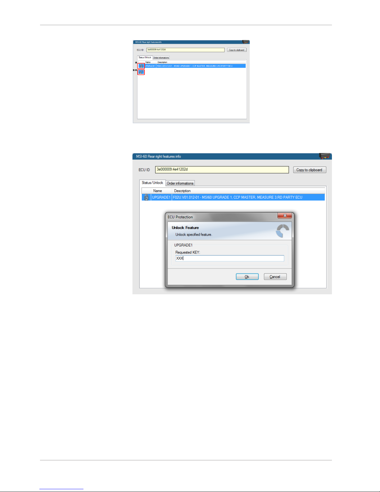
*Feature status Locked (disabled)
**Unlocked (activated)
2. Double-click on the feature you want to activate.
A feature unlock window appears.
3. Enter the activation key you received for this feature on this device and click ‘OK’
when done.
 Loading...