

Bosch MIC-550ALW36N, MIC-550ALB36N, MIC-550ALB28N Installation Manual
MIC Series 550 Camera
MIC Series 550
en Installation and User Manual


MIC Series 550 Camera Table of Contents | en 3
Table of Contents
1Preface 5
1.1 About this Manual 5
1.2 Conventions (Safety Precautions) in this Manual 5
1.3 Legal Information 5
2Safety 6
2.1 Important Safety Instructions 6
2.2 Important Notices 7
2.3 FCC and ICES Compliance 9
2.4 Bosch Notices 10
2.5 Customer Support and Service 11
3 Unpacking 12
3.1 Parts List 12
3.2 Additional Tools Required 12
4 Installation Overview 13
4.1 Typical Mounting Arrangements 14
4.2 Mounting Positions 15
5 Installation 16
5.1 Overview of Installation Steps 16
5.2 Canting the Camera 16
5.3 Adjusting the Rain Shield for Inverted Operation 17
5.4 Mounting the Camera 18
5.5 Lightning Protection 19
5.6 Electrical Connections 20
5.6.1 Composite Cable Color-coding 20
5.6.2 Alarm Inputs 21
5.6.3 Video 21
6 Getting Started 22
6.1 Establishing Control of the Camera 22
6.1.1 Establishing Control of the Camera via Biphase Protocol 22
6.1.2 Establishing Control of the Camera via RS-485 Protocol 22
6.2 Powering On 23
6.3 Controlling the Camera 23
6.3.1 Navigating the On-Screen Display (OSD) Menus 23
6.3.2 Basic Keyboard Operation 24
6.3.3 Keyboard Commands, Bosch Protocol 24
6.3.4 Keyboard Commands, Pelco Protocol 25
6.3.5 Special Preset Commands, Pelco Protocol 25
6.4 Setting the Camera Address via FastAddress 26
6.4.1 FastAddress, Bosch Protocol 26
6.4.2 FastAddress, Pelco Protocols 27
Bosch Security Systems, Inc. Installation Manual F.01U.239.454 | 1.0 | 2011.04

4 en | Table of Contents MIC Series 550 Camera
6.5 Setting Passwords 27
6.5.1 Special Passwords 27
6.5.2 Setting Passwords, Bosch Protocol 27
6.6 Configuring the Camera for Inverted Operation 28
7 On-Screen Display (OSD) Menus (Bosch Protocol) 29
7.1 Camera Setup Menu 30
7.2 Lens Setup Menu 32
7.3 PTZ Setup Menu 33
7.4 Display Setup Menu 34
7.5 Communication Setup Menu 36
7.6 Alarm Setup 37
7.7 Language Menu 41
7.8 Diagnostics Menu 41
8 On-Screen Display (OSD) Menus (Pelco Protocol) 44
8.1 Command Lock (locked) 44
8.2 Bosch Menu (locked) 45
8.3 Camera Setup 45
8.4 PTZ Setup (unlocked) 46
8.5 Other Menus 47
9 Common User Commands (unlocked) 48
9.1 Setting AutoPan Mode 48
9.2 Setting Preset Shots 48
9.3 Specifying a Shot or a Sector Title 48
9.4 Configuring Preposition Tours 49
9.5 Programming the Inactivity Operation 49
9.6 Recording Tours 50
9.7 Using the Wiper/Washer 50
9.8 Configuring Settings for IR Illumination 51
10 Advanced Features 52
10.1 Alarm Rules 52
10.1.1 Controlling Alarm Rules 52
10.1.2 Alarm Rule Examples 52
10.2 Privacy Masking 53
10.3 Image Stabilization 54
10.4 Pre-position Tour 54
10.5 Azimuth, Elevation, and Compass Directions 54
10.5.1 Setting the Azimuth Zero Point 54
10.5.2 Displaying Azimuth, Elevation, and Compass Headings 55
A Keyboard Commands by Number 56
F.01U.239.454 | 1.0 | 2011.04 Installation Manual Bosch Security Systems, Inc.
MIC Series 550 Camera Preface | en 5
1Preface
1.1 About this Manual
This user manual has been compiled with great care and the information it contains has been
verified thoroughly. The text was complete and correct at the time of printing. The ongoing
development of products means that the content can change without notice. Bosch Security
Systems accepts no liability for damage resulting directly or indirectly from faults,
incompleteness or discrepancies between the user guide and the product described.
1.2 Conventions (Safety Precautions) in this Manual
In this manual, the following symbols and notations are used to draw attention to special
situations:
DANGER!
This symbol indicates an imminently hazardous situation such as “Dangerous Voltage” inside
the product. If not avoided, this will result in an electrical shock, serious bodily injury, or
death.
WARNING!
Indicates a potentially hazardous situation. If not avoided, this could result in serious bodily
injury or death.
CAUTION!
Medium Risk
Indicates a potentially hazardous situation. If not avoided, this may result in minor or
moderate injury. Alerts the user to important instructions accompanying the unit.
CAUTION!
Indicates a potentially hazardous situation. If not avoided, this may result in property damage
or risk of damage to the unit.
NOTICE!
This symbol indicates information or a company policy that relates directly or indirectly to the
safety of personnel or protection of property.
1.3 Legal Information
Copyright
This user manual is the intellectual property of Bosch Security Systems, Inc. and is protected
by copyright. All rights reserved.
Trademarks
All hardware and software product names used in this document are likely to be registered
trademarks and must be treated accordingly.
Bosch Security Systems, Inc. Installation Manual F.01U.239.454 | 1.0 | 2011.04

6 en | Safety MIC Series 550 Camera
2Safety
Before installing and operating the camera, please read this manual carefully.
2.1 Important Safety Instructions
Read, follow, and retain for future reference all of the following safety instructions. Heed all
warnings on the unit and in the operating instructions before operating the unit.
1. Install in accordance with the manufacturer's instructions and in accordance with
applicable local codes.
2. Do not install the unit near any heat sources such as radiators, heaters, stoves, or other
equipment (including amplifiers) that produce heat.
3. Do not install the camera power supply near water for example near a bathtub,
washbowl, or swimming pool. The power supplies have an IP65 rating and are suitable
for outside installation; however, for security reasons, Bosch recommends that they are
installed in a suitable equipment cabinet. The camera unit is sealed to IP68 and can be
used safely in damp environments or outdoors, as long as the base cable connector is
suitably sealed.
4. Operate the unit only from the type of power source indicated on the label. Before
proceeding, be sure to disconnect the power from the cable to be installed into the unit.
– For external power supplied units, use only the recommended or approved power
supplies.
– For limited power source units, this power source must comply with EN60950.
Substitutions may damage the unit or cause fire or shock.
– For 24 VAC units, voltage applied to the unit's power input should not exceed ±10%,
or 28 VAC. User-supplied wiring must comply with local electrical codes (Class 2
power levels). Do not ground the supply at the terminals or at the unit's power
supply terminals.
– If unsure of the type of power supply to use, contact your dealer or local power
company.
5. Overloading - Do not overload outlets and extension cords. This can cause fire or
electrical shock.
6. Power disconnect - Units have power supplied whenever the power cord is inserted into
the power source. The power cord is the main power disconnect for all units.
7. Ventilation - The MIC Series 550 camera is a completely sealed unit and requires no
special consideration as regards to ventilation.
8. Power cord and plug protection - Protect the plug and power cord from foot traffic,
being pinched by items placed upon or against them at electrical outlets, and its exit
from the unit. For units intended to operate with 230 VAC, 50 Hz, the input and output
power cord must comply with the latest versions of IEC Publication 227 or IEC
Publication 245.
9. Lightning - For added protection during a lightning storm, or when leaving this unit
unattended and unused for long periods, unplug the unit from the wall outlet and
disconnect the cable system. This will prevent damage to the unit from lightning and
power line surges.
10. Object and liquid entry - With the exception of the base connector, the MIC Series 550
camera can be exposed to non corrosive liquids without damage. Never push objects into
the base connector as this may damage the connection pins and prevent the camera
operating correctly.
11. Controls adjustment - Adjust only those controls specified in the operating instructions.
Improper adjustment of other controls may cause damage to the unit.
F.01U.239.454 | 1.0 | 2011.04 Installation Manual Bosch Security Systems, Inc.

MIC Series 550 Camera Safety | en 7
12. Safety check - Safety checks should be performed upon completion of service or repairs
to the unit to ensure proper operating condition.
13. Attachments, changes or modifications - Only use attachments/accessories specified by
the manufacturer. Any change or modification of the equipment, not expressly approved
by Bosch, could void the warranty or, in the case of an authorization agreement, authority
to operate the equipment.
14. Cleaning - Unplug the unit from the outlet before cleaning. Follow any instructions
provided with the unit. Generally, using a dry cloth for cleaning is sufficient, but a moist
fluff-free cloth or leather shammy may also be used. Do not use liquid cleaners or aerosol
cleaners.
15. Servicing - Do not attempt to service this unit yourself. Opening or removing covers may
expose you to dangerous voltage or other hazards. Refer all servicing to qualified service
personnel.
16. Damage requiring service - Unplug the unit from the main AC power source and refer
servicing to qualified service personnel when any damage to the equipment has
occurred, such as:
– the power supply cord or plug is damaged;
– liquid has been spilled in the equipment;
– an object has fallen into the unit;
– the unit has been dropped or the unit cabinet is damaged;
– the unit exhibits a distinct change in performance;
– the unit does not operate normally when the user correctly follows the operating
instructions.
17. Replacement parts - Make sure that the service technician uses replacement parts
specified by the manufacturer, or that have the same characteristics as the original parts.
Unauthorized substitutions may cause fire, electrical shock, or other hazards.
2.2 Important Notices
Accessories - Do not place this unit on an unstable stand, tripod, bracket, or mount. The unit
may fall, causing serious injury and/or serious damage to the unit. Use only with the cart,
stand, tripod, bracket, or table specified by the manufacturer. When a cart is used, use
caution and care when moving the cart/apparatus combination to avoid injury from tip-over.
Quick stops, excessive force, or uneven surfaces may cause the cart/unit combination to
overturn. Mount the unit per the manufacturer's instructions.
All-pole power switch - Incorporate an all-pole power switch, with a contact separation of at
least 3 mm in each pole, into the electrical installation of the building.If it is needed to open
the housing for servicing and/or other activities, use this all-pole switch as the main
disconnect device for switching off the voltage to the unit.
Camera grounding - For mounting the camera in potentially damp environments, ensure to
ground the system using the ground connection of the power supply connector (see section:
Connecting external power supply).
Camera lens - An assembled camera lens in the outdoor housing must comply and be tested
in accordance with UL/IEC60950. Any output or signal lines from the camera must be SELV or
Limited Power Source. For safety reasons, the environmental specification of the camera lens
assembly must be within the environmental specification of -10 °C (14 °F) to 50 °C (122 °F).
Camera signal - Protect the cable with a primary protector if the camera signal is beyond 140
feet, in accordance with NEC800 (CEC Section 60).
Coax grounding:
– Ground the cable system if connecting an outside cable system to the unit.
Bosch Security Systems, Inc. Installation Manual F.01U.239.454 | 1.0 | 2011.04

8 en | Safety MIC Series 550 Camera
– Connect outdoor equipment to the unit's inputs only after this unit has had its grounding
plug connected to a grounded outlet or its ground terminal is properly connected to a
ground source.
– Disconnect the unit's input connectors from outdoor equipment before disconnecting
the grounding plug or grounding terminal.
– Follow proper safety precautions such as grounding for any outdoor device connected to
this unit.
U.S.A. models only - Section 810 of the National Electrical Code, ANSI/NFPA No.70, provides
information regarding proper grounding of the mount and supporting structure, grounding of
the coax to a discharge unit, size of grounding conductors, location of discharge unit,
connection to grounding electrodes, and requirements for the grounding electrode.
NOTICE!
This device is intended for use in public areas only.
U.S. federal law strictly prohibits surreptitious recording of oral communications.
Cold Start-ups - If camera is powered up in extremely cold temperature (for example, -40°C),
please allow 30 minutes warm-up after powering camera prior to operation. In some cases,
camera may require soft reset (Aux ON 911) or a power cycle before usable video is available.
Disposal - Your Bosch product was developed and manufactured with high-quality material
and components that can be recycled and reused. This symbol means that electronic and
electrical appliances, which have reached the end of their working life, must be collected and
disposed of separately from household waste material. Separate collecting systems are
usually in place for disused electronic and electrical products. Please dispose of these units at
an environmentally compatible recycling facility, per European Directive 2002/96/EC.
Environmental statement - Bosch has a strong commitment towards the environment. This
unit has been designed to respect the environment as much as possible.
Electrostatic-sensitive device - Use proper CMOS/MOS-FET handling precautions to avoid
electrostatic discharge.
NOTE: Wear required grounded wrist straps and observe proper ESD safety precautions when
handling the electrostatic-sensitive printed circuit boards.
Fuse rating - For security protection of the device, the branch circuit protection must be
secured with a maximum fuse rating of 16A. This must be in accordance with NEC800 (CEC
Section 60).
Grounding and polarization - This unit may be equipped with a polarized alternating current
line plug (a plug with one blade wider than the other blade). This safety feature allows the
plug to fit into the power outlet in only one way. If unable to insert the plug fully into the
outlet, contact a locally certified electrician to replace the obsolete outlet. Do not defeat the
safety purpose of the polarized plug.
Alternately, this unit may be equipped with a 3-pole grounding plug (a plug with a third pin for
earth grounding). This safety feature allows the plug to fit into a grounded power outlet only.
If unable to insert the plug into the outlet, contact a locally certified electrician to replace the
obsolete outlet. Do not defeat the safety purpose of the grounding plug.
Moving - Disconnect the power before moving the unit. Move the unit with care. Excessive
force or shock may damage the unit.
Outdoor signals - The installation for outdoor signals, especially regarding clearance from
power and lightning conductors and transient protection, must be in accordance with NEC725
and NEC800 (CEC Rule 16-224 and CEC Section 60).
Permanently connected equipment - Incorporate a readily-accessible disconnect device in
the building installation wiring.
F.01U.239.454 | 1.0 | 2011.04 Installation Manual Bosch Security Systems, Inc.

MIC Series 550 Camera Safety | en 9
Power lines - Do not locate the camera near overhead power lines, power circuits, or
electrical lights, nor where it may contact such power lines, circuits, or lights.
Video loss - Video loss is inherent to digital video recording; therefore, Bosch Security
Systems cannot be held liable for any damage that results from missing video information. To
minimize the risk of lost digital information, Bosch Security Systems recommends multiple,
redundant recording systems, and a procedure to back up all analog and digital information.
NOTICE!
This is a Class A product. In a domestic environment, this product may cause radio
interference, in which case the user may be required to take adequate measures.
2.3 FCC and ICES Compliance
FCC & ICES Information
(U.S.A. and Canadian Models Only)
This device complies with part 15 of the FCC Rules. Operation is subject to the following
conditions:
– this device may not cause harmful interference, and
– this device must accept any interference received, including interference that may cause
undesired operation.
NOTE: This equipment has been tested and found to comply with the limits for a Class A
digital device, pursuant to Part 15 of the FCC Rules and ICES-003 of Industry Canada. These
limits are designed to provide reasonable protection against harmful interference when the
equipment is operated in a commercial environment. This equipment generates, uses, and
radiates radio frequency energy and, if not installed and used in accordance with the
instruction manual, may cause harmful interference to radio communications. Operation of
this equipment in a residential area is likely to cause harmful interference, in which case the
user will be required to correct the interference at his expense.
Intentional or unintentional modifications, not expressly approved by the party responsible
for compliance, shall not be made. Any such modifications could void the user's authority to
operate the equipment. If necessary, the user should consult the dealer or an experienced
radio/television technician for corrective action.
The user may find the following booklet, prepared by the Federal Communications
Commission, helpful: How to Identify and Resolve Radio-TV Interference Problems. This booklet
is available from the U.S. Government Printing Office, Washington, DC 20402, Stock No. 004000-00345-4.
Informations FCC et ICES
(modèles utilisés aux États-Unis et au Canada uniquement)
Ce produit est conforme aux normes FCC partie 15. la mise en service est soumises aux deux
conditions suivantes :
– cet appareil ne peut pas provoquer d'interférence nuisible et
– cet appareil doit pouvoir tolérer toutes les interférences auxquelles il est soumit, y
compris les interférences qui pourraient influer sur son bon fonctionnement.
AVERTISSEMENT: Suite à différents tests, cet appareil s’est révélé conforme aux exigences
imposées aux appareils numériques de Classe A en vertu de la section 15 du règlement de la
Commission fédérale des communications des États-Unis (FCC). Ces contraintes sont destinées
à fournir une protection raisonnable contre les interférences nuisibles quand l'appareil est
utilisé dans une installation commerciale. Cette appareil génère, utilise et émet de l'energie
de fréquence radio, et peut, en cas d'installation ou d'utilisation non conforme aux
instructions, générer des interférences nuisibles aux communications radio. L’utilisation de ce
Bosch Security Systems, Inc. Installation Manual F.01U.239.454 | 1.0 | 2011.04

10 en | Safety MIC Series 550 Camera
produit dans une zone résidentielle peut provoquer des interférences nuisibles. Le cas
échéant, l’utilisateur devra remédier à ces interférences à ses propres frais.
Au besoin, l’utilisateur consultera son revendeur ou un technicien qualifié en radio/télévision,
qui procédera à une opération corrective. La brochure suivante, publiée par la Commission
fédérale des communications (FCC), peut s’avérer utile : How to Identify and Resolve Radio-TV
Interference Problems (Comment identifier et résoudre les problèmes d’interférences de radio
et de télévision). Cette brochure est disponible auprès du U.S. Government Printing Office,
Washington, DC 20402, États-Unis, sous la référence n° 004-000-00345-4.
2.4 Bosch Notices
Disclaimer
Underwriter Laboratories Inc. (“UL”) has not tested the performance or reliability of the
security or signaling aspects of this product. UL has only tested fire, shock and/or casualty
hazards as outlined in UL's Standard(s) for Safety for Closed Circuit Television Equipment, UL
2044. UL Certification does not cover the performance or reliability of the security or signaling
aspects of this product.
UL MAKES NO REPRESENTATIONS, WARRANTIES, OR CERTIFICATIONS WHATSOEVER
REGARDING THE PERFORMANCE OR RELIABILITY OF ANY SECURITY OR SIGNALING RELATED
FUNCTIONS OF THIS PRODUCT.
Disclaimer
Underwriter Laboratories Inc. (“UL”) has not tested the performance or reliability of the
security or signaling aspects of this product. UL has only tested fire, shock and/or casualty
hazards as outlined in UL's Standard(s) for Safety for Information Technology Equipment, UL
60950-1. UL Certification does not cover the performance or reliability of the security or
signaling aspects of this product.
UL MAKES NO REPRESENTATIONS, WARRANTIES, OR CERTIFICATIONS WHATSOEVER
REGARDING THE PERFORMANCE OR RELIABILITY OF ANY SECURITY OR SIGNALINGRELATED FUNCTIONS OF THIS PRODUCT.
F.01U.239.454 | 1.0 | 2011.04 Installation Manual Bosch Security Systems, Inc.

MIC Series 550 Camera Safety | en 11
2.5 Customer Support and Service
If this unit needs service, contact the nearest Bosch Security Systems Service Center for
authorization to return and shipping instructions.
Service Centers
USA
Telephone: 800-366-2283 or 585-340-4162
Fax: 800-366-1329
Email: cctv.repair@us.bosch.com
Customer Service
Telephone: 888-289-0096
Fax: 585-223-9180
Email: security.sales@us.bosch.com
Technical Support
Telephone: 800-326-1450
Fax: 585-223-3508 or 717-735-6560
Email: technical.support@us.bosch.com
Repair Center
Telephone: 585-421-4220
Fax: 585-223-9180 or 717-735-6561
Email: security.repair@us.bosch.com
Canada
Telephone: 514-738-2434
Fax: 514-738-8480
Europe, Middle East & Africa Region
Please contact your local distributor or Bosch sales office. Use this link:
http://www.boschsecurity.com/startpage/html/europe.htm
Asia Pacific Region
Please contact your local distributor or Bosch sales office. Use this link:
http://www.boschsecurity.com/startpage/html/asia_pacific.htm
More Information
For more information please contact the nearest Bosch Security Systems location or visit
www.boschsecurity.com
Bosch Security Systems, Inc. Installation Manual F.01U.239.454 | 1.0 | 2011.04

12 en | Unpacking MIC Series 550 Camera
3 Unpacking
This equipment should be unpacked and handled with care. If an item appears to have been
damaged in shipment, notify the shipper immediately.
Verify that all the parts listed in the Parts List below are included. If any items are missing,
notify your Bosch Security Systems Sales or Customer Service Representative.
The original packing carton is the safest container in which to transport the unit and must be
used if returning the unit for service. Save it for possible future use.
NOTICE!
Do not stand the canted (45°) MIC Series 550 camera upright as it is unstable unless properly
mounted.
3.1 Parts List
The package containing the MIC Series 550 camera should include the following items:
Quantity Part
1 MIC Series 550 Camera
1 Nebar gasket
3.2 Additional Tools Required
The following table lists additional tools required (not supplied by Bosch):
Quantity Part
1 13 mm wrench for the PCD foot, fixing bolts
1 3 mm screwdriver for the terminal blocks in power supply
1 8 mm screwdriver for fixing screws for MIC Series PSU enclosure
1 No. 2 Phillips screwdriver for adjusting the rain shield, if required
1 Silicone sealant for ensuring a water tight seal [if not using the Nebar gasket]
F.01U.239.454 | 1.0 | 2011.04 Installation Manual Bosch Security Systems, Inc.
MIC Series 550 Camera Installation Overview | en 13
4 Installation Overview
CAUTION!
Installation should be made by qualified service personnel and conform to the National
Electrical Code and applicable local codes.
The MIC Series cameras are designed for easy installation on a variety of common fittings. The
most common type of mount used is a dedicated CCTV camera pole where the camera is
bolted directly to the top using industry-standard 4 in. (101.6 mm) fitting. This type of camera
pole provides a robust mounting platform that minimizes camera motion and typically has a
large base cabinet for mounting ancillary equipment such as power supplies.
The camera can also be mounted on lamp post columns using the Pole Mount Bracket (MICPMB); however, users should be aware that lamp posts can often be subject to movement and
are not suitable platforms in all conditions or for all applications.
For mounting directly onto buildings, Bosch Security Systems manufactures a range of
brackets suitable for all typical building installations for upright (90°), Inverted, or canted
(45°) positions.
Figure 4.1 MIC camera mounting positions: Inverted, Upright, and Canted
The camera’s adaptability enables easy integration in a wide variety of mobile and redeployable installations. These have included lifeboats and other surface/subsurface vessels,
emergency service vehicles, highway agency vehicles, council/contractor parking enforcement
vehicles, and crowd-control vehicles.
Bosch Security Systems, Inc. Installation Manual F.01U.239.454 | 1.0 | 2011.04
14 en | Installation Overview MIC Series 550 Camera
4.1 Typical Mounting Arrangements
Below are examples of typical mounting arrangements for MIC Series cameras.
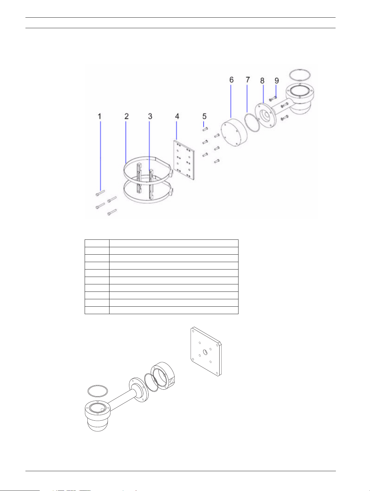
Figure 4.2 Typical pole mount (from left to right: Pole Mount Bracket (MIC-PMB), Shallow Conduit Adapter
(MIC-SCA), and Wall Mount Bracket (MIC-WMB))
Number Description
1 Securing bolts for Shallow Conduit Adapter
2 90 mm stainless steel pole banding
3 Blocks for Pole Mount Bracket
4 Plate for Pole Mount Bracket
5 Securing bolts for plate for Pole Mount Bracket
6 Shallow Conduit Adapter
7“O” ring
8 Wall Mount Bracket
9 Securing bolts for Wall Mount Bracket
Figure 4.3 Typical wall mount (from left to right: Wall Mount Bracket (MIC-WMB), Shallow Conduit Adapter
(MIC-SCA), and Spreader Plate (MIC-SPR))
F.01U.239.454 | 1.0 | 2011.04 Installation Manual Bosch Security Systems, Inc.
MIC Series 550 Camera Installation Overview | en 15
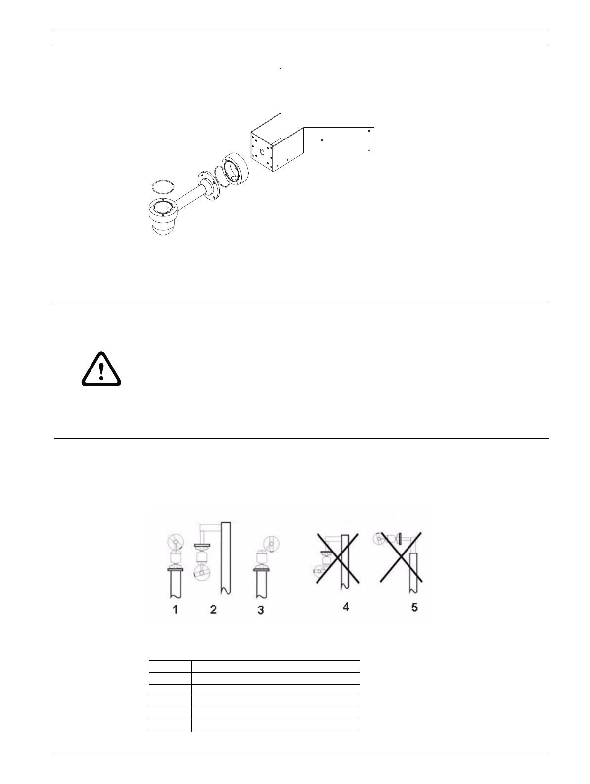
Figure 4.4 Typical corner mount (from left to right: Wall Mount Bracket (MIC-WMB), Shallow Conduit
Adapter (MIC-SCA), and Corner Mount Bracket (MIC-CMB))
4.2 Mounting Positions
CAUTION!
The upright unit can be mounted either with the camera ball up or down. To get the picture
the correct way for installation with the camera ball down, rotate the camera tilt axis 180°. For
more information, see Section 6.6 Configuring the Camera for Inverted Operation, Page 28.
If the camera is mounted ball down, it is essential that the connector and base area of the
camera are completely sealed from water ingress. Any water getting into the connector is
liable to cause corrosion to the connector pins, leading to unreliable operation of the camera
unit. To prevent water penetrating the composite cable connector threads, seal the 25 mm
thread at final installation using PTFE tape. Alternately, a suitable sealant may be liberally
applied to the thread prior to final tightening.
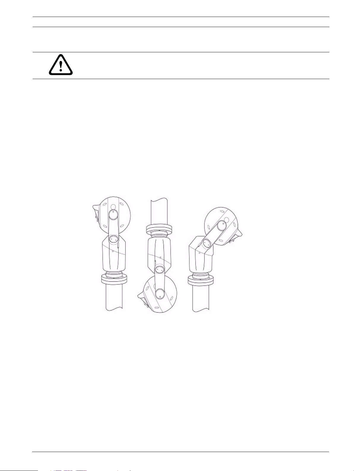
The MIC Series 400 cameras (AL, IR, ST), if canted, are designed to be mounted upright
(straight up, 90°), inverted (straight down, 90°), or canted upright (ball up, 45°). The tilt limits
for the canted unit prevent it from working properly if mounted ball down. See the figure
below for the correct ways to mount the camera.
Figure 4.5 Mounting diagram: Correct and Incorrect ways (1 = Upright; 2 = Inverted; 3 = Canted; 4 = inverted
canted; 5 = inverted on top of pole)
Number Description
1 Correct way, Upright
2 Correct way, Inverted
3 Correct way, Canted
4 Incorrect way, inverted and canted
5 Incorrect way, inverted on top of pole
Bosch Security Systems, Inc. Installation Manual F.01U.239.454 | 1.0 | 2011.04
16 en | Installation MIC Series 550 Camera
5 Installation
5.1 Overview of Installation Steps
Follow these steps in sequence to install the MIC-550 camera.
Note: Depending on your desired mounting position and location, as well as your chosen
accessories, you may not need to complete every step.
1. Cant the camera. See Section 5.2 Canting the Camera, page 16.
2. Reverse the rain shield (for cameras mounted in inverted position). See
Section 5.3 Adjusting the Rain Shield for Inverted Operation, page 17.
3. Mount the camera. See Section 5.4 Mounting the Camera, page 18.
4. Mount the power supply unit (PSU). See the MIC Series Power Supplies Installation
Manual that came with the PSU (sold separately from the camera).
5. Make the necessary connections for power, telemetry, and video. See
Section 5.6 Electrical Connections, page 20.
6. Connect the camera to the computer. See Section 6 Getting Started.
7. Configure the camera for inverted operation (for cameras mounted in inverted
position). See Section 6.6 Configuring the Camera for Inverted Operation, page 28.
5.2 Canting the Camera
The MIC-550 features twist-lock on-site canting functionality. This allows the camera to be
installed upright (90°), inverted, or canted (45º) to achieve the perfect field of view. Installers
can adjust the camera from an upright position to a canted position if desired.
The following graphic shows the camera in both upright and canted positions.
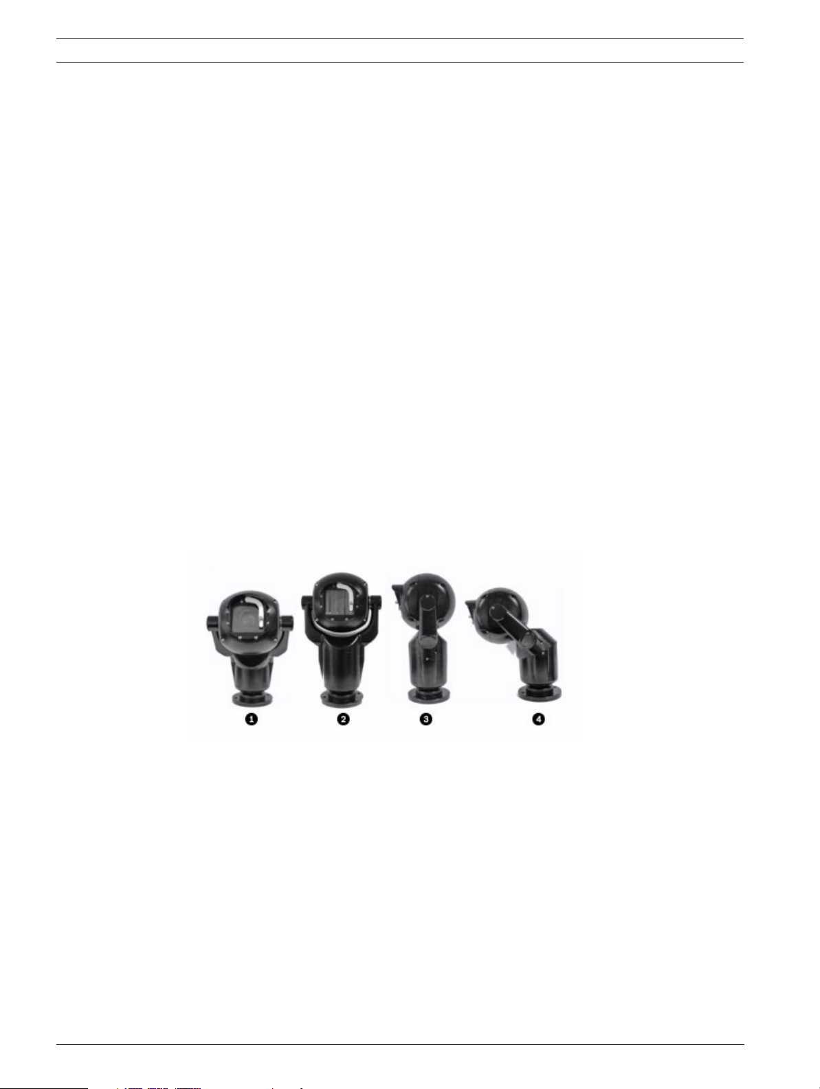
Figure 5.1 MIC-550 cameras (from left: Front view, canted (1); Front view, upright (2); Side view, upright
(3); Side view, canted (4))
To cant the camera, follow these steps:
1. Firmly secure the camera base by the 4-inch PCD foot bolts.
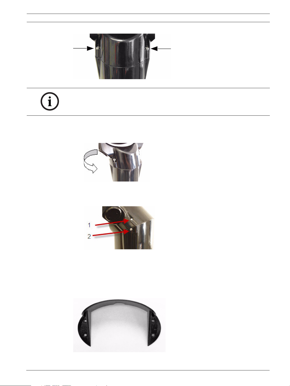
2. Locate and remove the two (2) pan body fixing screws (identified by arrows in Figure 5.2
below). Once the screws have been loosened, lift them up and continue turning to lock
the screws open. Ensure not to damage the paint work on the camera.
F.01U.239.454 | 1.0 | 2011.04 Installation Manual Bosch Security Systems, Inc.
MIC Series 550 Camera Installation | en 17
Figure 5.2 Pan body fixing screws
NOTICE!
The small security screws (identified in Figure 5.4 below) are not designed to be removed. Any
attempt to remove these screws will void the warranty and potentially cause serious damage
to the camera.
3. Grasp the lower camera body beneath the pan body joint and then carefully twist the
upper camera body clockwise, as shown in Figure 5.3 below, until the camera body has
rotated 180° around. The top part of the camera will now be at a 45° angle (canted).
Figure 5.3 Canting in progress
4. Align the two (2) pan body fixing screws, then carefully replace and tighten them. The
camera is now ready to be installed and configured.
Figure 5.4 Camera in canted position; arrows point to pan body fixing screws (1) and security screws (2)
5.3 Adjusting the Rain Shield for Inverted Operation
The upright unit can be mounted with the camera ball up or down. When the camera will be in
inverted position, you should reverse the rain shield to provide weather protection for the
window glass.
Figure 5.5 Rain shield
Bosch Security Systems, Inc. Installation Manual F.01U.239.454 | 1.0 | 2011.04
18 en | Installation MIC Series 550 Camera
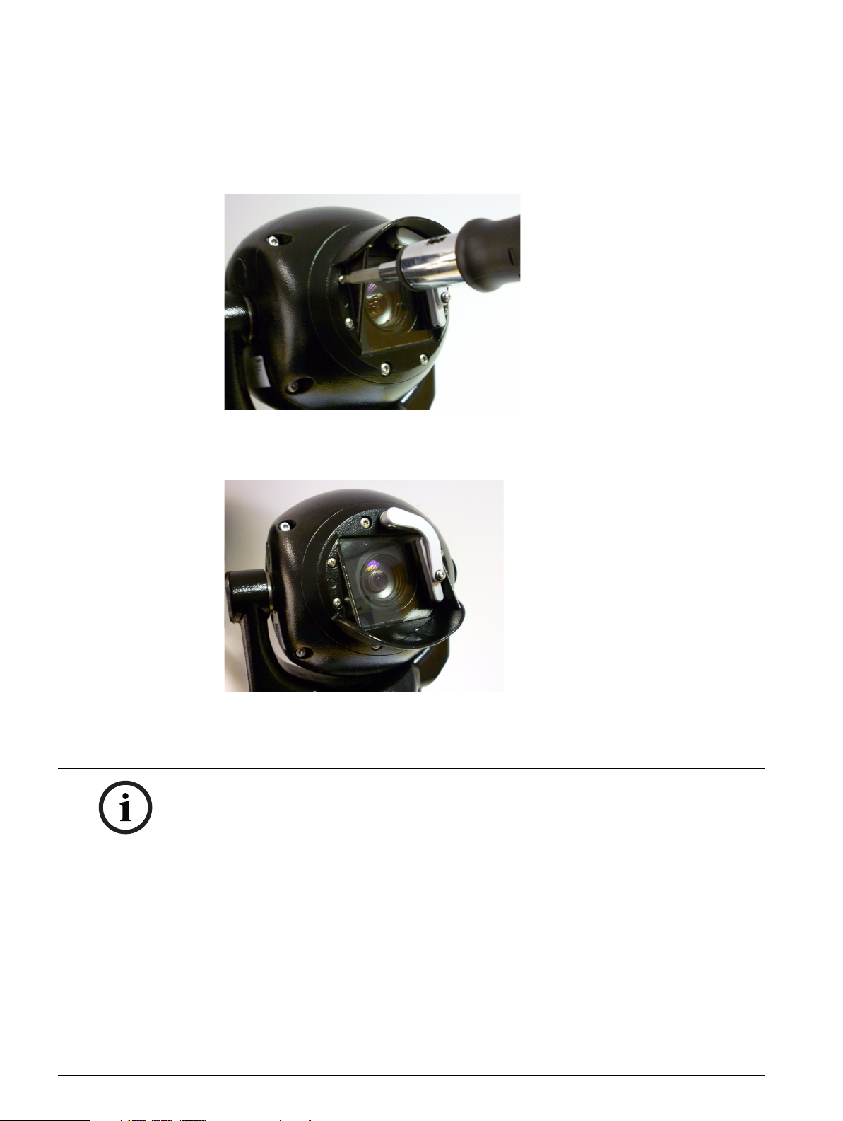
To reverse the rain shield, follow these steps:
1. Remove the four (4) M3 x 6 screws that hold the rain shield to the face of the camera.
Two screws are on the left of the rain shield; two screws are on the right of the rain
shield.
Figure 5.6 Screw removal
2. Reverse the rain shield.
3. Reattach the rain shield to the camera face.
Figure 5.7 Inverted rain shield installed on camera
5.4 Mounting the Camera
NOTICE!
Installation should be made by qualified service personnel and conform to the National
Electrical Code and applicable local codes. Ensure a strong safety chain is used to secure the
camera to prevent any danger of dropping the product during installation.
To mount a MIC Series camera, follow these steps:
1. Identify a secure location for the mount (supplied separately) and for the camera. Locate
the mounting position so that the camera cannot be interfered with either intentionally or
accidentally.
2. Ensure that the mounting surface is capable of supporting the combined weight of the
camera and mounting hardware under all expected conditions of load, vibration, and
temperature.
3. Fit the mounting brackets securely, observing all appropriate safety precautions and local
building regulations.
4. Carefully lift the camera to the mounting point.
F.01U.239.454 | 1.0 | 2011.04 Installation Manual Bosch Security Systems, Inc.
 Loading...